

Page 1
Pro-Doweling Kit
USER’S MANUAL
#840
Please read this manual carefully and thoroughly
before using this product.
Page 2

General Tools & Instruments would like to
thank you for your purchase.
For more information on our complete line of products,
visit www.GeneraITools.com
TABLE OF CONTENTS
Package Contents . . . . . . . . . . . . . . . . . . . . . . . . . . . . . . . . . . . 3
Safety Instructions . . . . . . . . . . . . . . . . . . . . . . . . . . . . . . . . . . 3
Before You Get Started . . . . . . . . . . . . . . . . . . . . . . . . . . . . . . . 3
Selecting Dowel Size . . . . . . . . . . . . . . . . . . . . . . . . . . . . . . . . . 4
Instructions For Edge-To-Edge Joints . . . . . . . . . . . . . . . . 5 –6
Instruction For Use Of Dowel Centers . . . . . . . . . . . . . . . . . . . . 7
Instructions For T-Butt Joints . . . . . . . . . . . . . . . . . . . . . . . 8 –9
Instructions For Corner Joints . . . . . . . . . . . . . . . . . . . . 10 – 11
Instructions in Spanish . . . . . . . . . . . . . . . . . . . . . . . . . . 12 – 21
Instructions in French . . . . . . . . . . . . . . . . . . . . . . . . . . . 22 – 32
2
Page 3
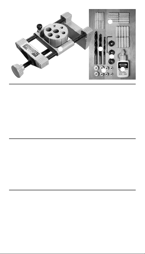
PACKAGE CONTENTS:
1 Doweling Jig
Brad Point Drill Bits, 1/4", 5/16", 3/8"
Dowel and Tenon Centers Set from 3/16" ID to 1/2" OD
3 Drill Stops 1/4", 5/16", 3/8"
30 Dowel Pins, 10 Each 1/4", 5/16", 3/8"
Wood Glue
SAFETY INSTRUCTIONS
1. ALWAYS USE EYE PROTECTION WHEN USING POWER
TOOLS. WEAR SAFETY GOGGLES THAT COMPLY TO
ANSI 287.1.
2. WARNING: ALWAYS UNPLUG DRILL FROM POWER SUPPLY
WHEN CHANGING BITS AND ATTACHING DRILL STOPS.
BEFORE YOU GET STARTED
1. Practice drilling dowel holes and making joints in scrap
pieces of wood to get familiar with the dowel jig.
2. Make all markings on the boards exactly as described in the
instructions to avoid drilling in the wrong locations.
3. Avoid drilling holes too deep.
4. Before gluing dowels, fit the pieces together to make sure
you are satisfied with the line up.
3
Page 4
SELECTING DOWEL SIZE
The dowel size is limited by the thickness of the work piece.
Use Table 1 to help you choose the proper dowel size for your
project.
Board Thickness Dowel Size
1/2" – 9/16" 3/16" or 1/4"
5/8" – 11/16" 5/16"
11/16" – 15/16" 3/8"
1" or greater 7/16" or 1/2"
Table 1
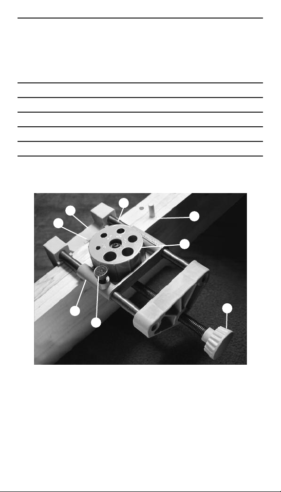
C
D
A. SCORE LINE
B. CLAMP SCREW
C. FIXED JAW
D. INDEX MARK
4
G
A
H
F
E
B
E. SLIDE LOCK SCREW
F. SLIDE
G. SCALE ROD
H. TURRET
Page 5
INSTRUCTIONS FOR
EDGE-TO-EDGE JOINTS
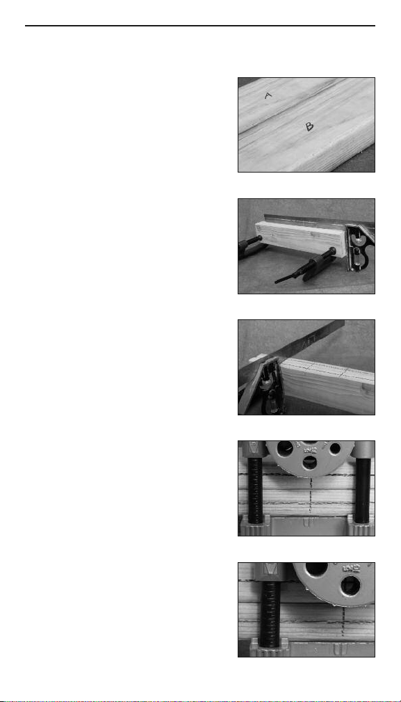
1. Place boards that you want to join
in the final position and mark them
“A” and “B” (See Figure 1).
2. Now position the boards so the
surfaces to be joined face you.
Using a square, align the edges of
the boards (See Figure 2). NOTE:
To fit in the jig, the combined
width of both boards must not
exceed 4 inches. When the
combined width exceeds 4 inches,
only one board can be in the jig at
a time (See Figure 2).
3. Once aligned, use a clamp to
secure the boards.
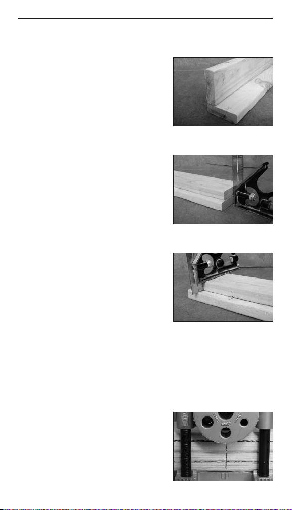
4. Using the square again, mark a
line across both boards at the
locations you want to drill dowel
holes (See Figure 3).
5. Open the CLAMP SCREW (B) on
the jig wide enough to fit over the
boards.
6. Place the FIXED JAW (C) of the jig
against the side of board “A” and
align the center of the INDEX MARK
(D) with one of the lines marked on
the boards. (See Figure 4)
7. Gently tighten CLAMP SCREW (B).
8. Loosen SLIDE LOCK SCREW (E)
and move SLIDE (F) along the
SCALE ROD (G) until centered on
board “A”. Use the graduations
marked on the SCALE ROD (G) to
center the SLIDE (F) (See Figure 5).
Once aligned, tighten SLIDE LOCK
SCREW (E).
Figure 1
Figure 2
Figure 3
Figure 4
Figure 5
5
Page 6
EXAMPLE: If both of the boards to be joined are each one inch
thick, move the SLIDE (F) so the arrow aligns with the 1/2"
graduation on the SCALE ROD (G) to drill the first hole. Then
move the SLIDE (F) so the arrow aligns with the 1-1/2"
graduation on the SCALE ROD (G) to drill the second hole.
9. Lift TURRET (H) and turn until the correct size hole is aligned
with the INDEX MARK (D). The TURRET (H) will snap into
place when properly located.
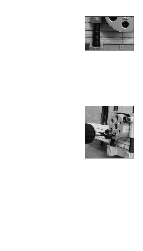
10. ENSURE THE DRILL IS TURNED OFF. Place a depth stop
collar on the drill bit at the proper depth to drill the first hole.
NOTE: Position the collar to allow for TURRET (H) height as
well as desired depth of hole.
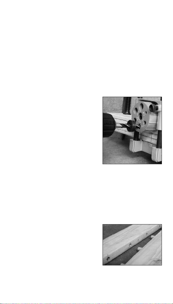
11. Ensure SLIDE (F) is locked at
proper position and drill dowel
hole in board “A”. The hole in the
TURRET (H) will help you keep
the drill straight (See Figure 6).
12. Loosen SLIDE LOCK SCREW (E)
and move SLIDE (F) until
positioned at board “B” center
location.
13. Tighten SLIDE LOCK SCREW (E)
Figure 6
and drill hole in board “B” .
14. With clamp in place, loosen the jig CLAMP SCREW (B) and
move the jig so the next marked location on the boards
aligns with the INDEX MARK (D) on the jig.
15. Gently tighten the CLAMP SCREW (B) and repeat steps 8-14
until all dowel holes are drilled.
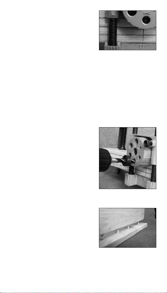
16. Apply glue to the dowel pins and
insert them in the holes in board
“A”. Align the holes in board “B”
with dowel pins connect boards
“A” and “B” to make the joint
(See Figure 7).
Figure 7
6
Page 7
INSTRUCTION FOR USE OF
DOWEL CENTERS
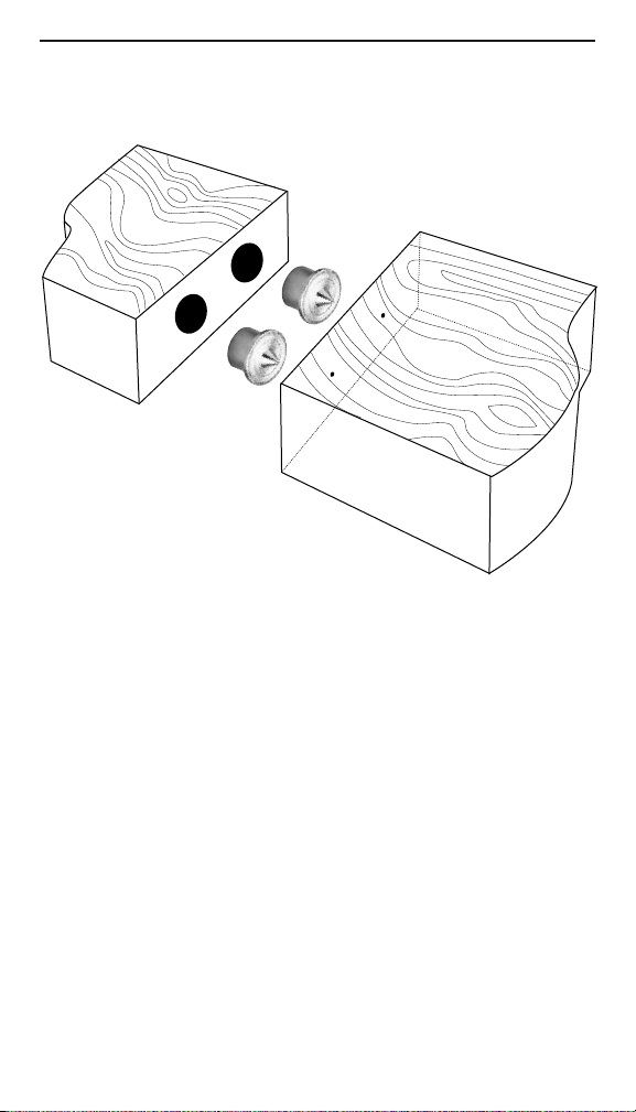
These dowel centers help to make it easy to precisely align the
holes of two pieces of stock to be joined by a doweled joint—
for example, a shelf and each of its supports. They can be used
in conjunction with a dowel jig to show where the joining holes
need to be drilled.
Drill one set of holes with a diameter of 1/4'', 5/16'', 3/8''
or 1/2'' in one piece of stock (see photo). Slip the dowel centers
of corresponding diameter into the holes, with the sharp points
facing out. Then align the two pieces of stock by hand and press
them together. The sharp points will leave marks on the second
piece of stock indicating exactly where to drill the second set of
holes.
To remove the dowel centers, hit the other side of the stock
with a rubber mallet.
7
Page 8
INSTRUCTIONS FOR T-BUTT JOINTS
NOTE: When using this jig to make T-Butt joints, the width of
either surface to be drilled cannot exceed 4 inches.
1. Place boards you want to join in
the final position and mark them
“A” and “B”. Use a square to align
the two boards and mark a line
along the edge of board “A” on
the short side of board “B” (See
Figure 8).
2. Flip board “A” flat so it lies on
board “B”. Use a square to ensure
the edges are still aligned (See
Figure 9). Clamp the boards
together.
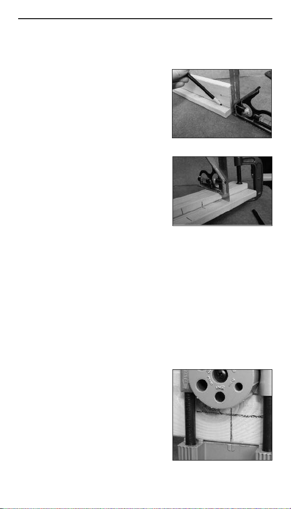
3. Use the square to mark the edge
of board “A” and the surface of
board “B” to be drilled at all
desired dowel pin locations
(See Figure 9).
4. Remove the clamp and place board “A” in the jig as detailed
in “HOW TO MAKE EDGE-TO-EDGE JOINTS”, steps 5-7.
5. Drill holes in board “A” at all desired locations. Follow steps
8-15 in “HOW TO MAKE EDGE-TO-EDGE JOINTS.”
6. Remove board “A” from the jig once all holes are drilled.
7. Open the CLAMP SCREW (B) on the jig wide enough to fit over
the board “B” with surface to be drilled facing up.
8. Place the FIXED JAW (C) of the jig
against the side of board “B” that
is closer to the marked line from
step 1. Align the center of the
INDEX MARK (D) with one of the
lines marked, from step 3, on the
board. (See Figure 10)
Figure 8
Figure 9
Figure 10
8
Page 9
9. Loosen SLIDE LOCK SCREW (E)
and, starting from the marked
line on board “B”, move the
SLIDE (F) along the SCALE ROD
(G) until the distance the SLIDE
(F) is away from the line is half
the thickness of board “A”. Use
the graduations marked on the
SCALE ROD (G) for measuring (See Figure 11).
Once aligned, tighten SLIDE LOCK SCREW (E).
10. Lift TURRET (H) and turn until the correct size hole is
aligned with the INDEX MARK (D). The TURRET (H) will snap
into place when properly located.
11. ENSURE THE DRILL IS TURNED OFF. Place a depth stop
collar on the drill bit at the proper depth to drill the first hole.
NOTE: Position the collar to allow for TURRET (H) height as
well as desired depth of hole.
12. Ensure SLIDE (F) is locked at
proper position and drill dowel
hole in board “B”. The hole in the
TURRET (H) will help you keep
the drill straight (See Figure 12).
13. With clamp in place, loosen the
jig CLAMP SCREW (B) and move
the jig so the next marked
location on the board aligns with
the INDEX MARK (D) on the jig.
14. Gently tighten the CLAMP SCREW
(B) and repeat steps 8-13 until all
dowel holes are drilled.
15. Apply glue to the dowel pins and
insert them in the holes in board
“A” . Align the holes in board “B”
with dowel pins connect boards
“A” and “B” to make the joint
(See Figure 13).
Figure 11
Figure 12
Figure 13
9
Page 10
INSTRUCTIONS FOR
CORNER JOINTS
NOTE: When using this jig to make
corner joints, the width of either
surface to be drilled cannot exceed
4 inches.
1. Place boards you want to join in
the final position and mark them
“A” and “B”. Use a square to
ensure proper alignment
(See Figure 14).
2. Flip board “A” flat so it lies on
board “B”. Use a square to ensure
the edges are still aligned
(See Figure 15). Clamp the boards
together.
3. Use the square to mark the edge
of board “A” and the surface of
board “B” to be drilled at all
desired dowel pin locations
(See Figure 16).
4. Remove the clamp and place
board “A” in the jig as detailed in
“HOW TO MAKE EDGE-TO-EDGE
JOINTS”, steps 5-7.
5. Drill holes in board “A” at all desired locations.
Follow steps 8-15 in “HOW TO MAKE EDGE-TO-EDGE
JOINTS.”
6. Remove board “A” from the jig once all holes are drilled.
7. Open the CLAMP SCREW (B) on the jig wide enough to fit over
the board “B” with surface to be drilled facing up.
8. Place the FIXED JAW (C) of the jig
against the side of board “B” that
is closest to the marked lines from
step 3. Align the center of the
INDEX MARK (D) with one of the
lines marked, from step 3, on the
board. (See Figure 17)
10
Figure 14
Figure 15
Figure 16
Figure 17
Page 11
9. Loosen SLIDE LOCK SCREW (E)
and move the SLIDE (F) along the
SCALE ROD (G) until the distance
the SLIDE (F) is away from the
edge is half the thickness of board
“A”, Use the graduations marked
on the SCALE ROD (G) for
measuring (See Figure 18),
Once aligned, tighten SLIDE
Figure 18
LOCK SCREW (E).
10. Lift TURRET (H) and turn until the correct size hole is aligned
with the INDEX MARK (D), The TURRET (H) will snap into
place when properly located.
11. ENSURE THE DRILL IS TURNED OFF. Place a depth stop
collar on the drill bit at the proper depth to drill the first hole,
NOTE: Position the collar to allow
for TURRET (H) height as well as
desired depth of hole.
12. Ensure SLIDE (F) is locked at
proper position and drill dowel
hole in board “B”, The hole in the
TURRET (H) will help you keep
the drill straight (See Figure 19).
13. With clamp in place, loosen the
jig CLAMP SCREW (B) and move
the jig so the next marked
location on the board aligns with
Figure 19
the INDEX MARK (D) on the jig,
14. Gently tighten the CLAMP SCREW (B) and repeat steps 8–13
until all dowel holes are drilled,
15. Apply glue to the dowel pins and insert them in the holes in
board “A”, AIign the holes in board “B” with dowel pins
connect boards “A” and “B” to make the joint.
11
Page 12

Juego de Amortajadora
Profesional
GUIA DEL USUARIO
#840
Por favor lea cuidadosamente esta guía del usuario
12
antes de utilizar éste producto.
Page 13

GRACIAS:
General Tools & Instruments desea agradecerle por su compra.
Para más información sobre nuestra línea completa de productos,
visite: www.GeneralTools.com
CONTENIDO DEL PAQUETE
1 Amortajadora
Brocas para Madera de 1/4", 5/16" y 3/8"
Juego de guías para centros de orificios y espigas de
3/16" de Diám. Int. a 1/2" de Diám. Ext.
3 topes para brocas de 1/4", 5/16" y 3/8"
30 espigas: 10 de 1/4", 10 de 5/16" y 10 de 3/8"
Cola para madera
INSTRUCCIONES DE SEGURIDAD
1. SIEMPRE USE PROTECTOR OCULAR CUANDO TRABAJE
CON HERRAMIENTAS MOTORIZADAS. SIEMPRE USE
GAFAS DE SEGURIDAD QUE CUMPLAN CON LA NORMA
ANSI 287.1.
2. ADVERTENCIA: SIEMPRE DESCONECTE EL TALADRO DEL
SUMINISTRO ELÉCTRICO AL CAMBIAR LAS MECHAS O AL
INSTALAR LOS TOPES PARA MECHAS.
13
Page 14

ANTES DE COMENZAR
1. Practique taladrar orificios de mortaja y hacer juntas con
espigas en retazos de madera para familiarizarse con la
amortajadora.
2. Para evitar taladrar en lugares equivocados, haga todas las
marcas en los tableros exactamente como se describe en
las instrucciones.
3. Evite taladrar orificios demasiado profundos.
4. Antes de encolar las espigas, encaje las piezas para
asegurarse de estar satisfecho con el alineamiento.
SELECCIÓN DEL DIÁMETRO DE LAS ESPIGAS
El diámetro de las espigas está limitado por el espesor de la
pieza de trabajo. Use la Tabla 1 como referencia para
seleccionar el diámetro adecuado para las espigas de su
proyecto.
Espesor de la tabla Diámetro de la Espiga
1/2" – 9/16" 3/16" ó 1/4"
5/8" – 11/16" 5/16"
11/16" – 15/16" 3/8"
1" ó más 7/16" ó 1/2"
Tabla 1
C
D
F
G
A
H
E
A: RAYE LA LÍNEA
B: TORNILLO DE LA
PRENSA
C: MANDÍBULA FIJA
D: MARCA DE ÍNDICE
E: TORNILLO DEL
SEGURO
B
DEL DESLIZADOR
F: DESLIZADOR
G: VARILLA DE
ESCALA
H: TORRETA
14
Page 15

INSTRUCCIONES PARA JUNTAS DE CANTO
CON CANTO
1. Coloque las tablas que desea unir
en su posición final y márquelas
“A” y “B”. (Vea la Figura 1).
2. Ahora posicione las tablas con las
superficies a unirse hacia usted.
Alinee los bordes de las tablas con
una escuadra (Vea la Figura 2).
NOTA: Para insertar las dos tablas
a la vez en la amortajadora, el
espesor combinado no debe
exceder 10cm (4"); de lo contrario
sólo se podrá amortajar una tabla
a la vez. (Vea la Figura 2).
3. Una vez alineadas, fíjelas con una
sargenta.
4. Usando la escuadra nuevamente,
trace una línea a través de las dos
tablas en la posición donde desea
taladrar los orificios para las
espigas (Vea la Figura 3).
5. Abra el tornillo de la quijada (B) de
la amortajadora lo suficiente para
que quepan las dos tablas.
6. Coloque la quijada fija (C) de la
amortajadora contra el costado de
la tabla “A” y alinee el centro de la
marca de ÍNDICE (D) con una de
las líneas marcadas en las tablas.
(Vea la Figura 4).
7. Ajuste cuidadosamente el tornillo
de la quijada (B).
8. Afloje el TORNILLO de seguro de
deslizamiento (E) y mueva el
DESLIZADOR (F) a lo largo de la
VARILLA DE ESCALA (G) hasta
centrarlo en la tabla “A”. Use las
Figura 1
Figura 2
Figura 3
Figura 4
Figura 5
15
Page 16

graduaciones en LA VARILLA DE ESCALA (G) para centrar el
DESLIZADOR (F) (Vea la Figura 5). Una vez alineado, ajuste el
TORNILLO de seguro de deslizamiento lateral (E).
EJEMPLO: Si cada una de las tablas a unirse tiene una
pulgada de espesor, para taladrar el primer orificio, mueva
el DESLIZADOR (F) alineando la flecha con la marca de 1/2"
en la Varilla de Escala (G). Luego, para taladrar el segundo
orificio mueva el Deslizador (F) alineando la flecha con la
marca de 1-1/2" en la Varilla de Escala (G).
9. Levante la torreta (H) y gírela hasta que el orificio guía del
diámetro correcto se alinee con la MARCA DE ÍNDICE (D).
La torreta enganchará cuando se posicione
apropiadamente.
10. CERCIÓRESE QUE EL TALADRO ESTÉ APAGADO. Coloque el
collar de tope en la broca a la altura apropiada para taladrar
el primer orificio. NOTA: Posicione el collar teniendo en
cuenta la altura de la TORRETA
(H) así como la profundidad
deseada para el orificio.
11. Cerciórese que el DESLIZADOR
(F) esté asegurado en la posición
correcta y taladre el orificio en la
tabla “A”. El orificio en la
TORRETA “H” le ayudará a
mantener el taladro derecho
(Vea la Figura 6).
12. Afloje el TORNILLO de seguro de
deslizamiento (E) hasta colocarlo
Figura 6
sobre el centro de la tabla “B”.
13. Ajuste el tornillo de seguro de deslizamiento (E) y taladre
un orificio en la tabla “B”.
14. Con la prensa (sargenta) en posición, afloje el tornillo de la
quijada (B) y mueva la amortajadora hasta alinear su
MARCA DE ÍNDICE (D) con la marca del siguiente punto a
taladrar.
15. Ajuste cuidadosamente el tornillo de la quijada (B) y repita
los pasos 8 al 14 hasta taladrar todos los orificios para las
espigas.
16
Page 17

16. Aplique cola a las espigas e
insértelas en los orificios de
mortaja en la tabla “A”. Alinee los
orificios en la tabla “B” con las
espigas en la tabla “A” y junte las
dos tablas. (Vea la Figura 7).
Figura 7
INSTRUCCIONES PARA GUÍAS DE CENTRADO
Estas guías de centrado facilitan el alineamiento preciso de los
orificios de las dos piezas de madera que deberán unirse –por
ejemplo, un entrepaño y cada uno de sus soportes. Se pueden
utilizar junto con una plantilla para mostrar el lugar en donde se
deberá efectuar las perforaciones.
Efectúe un par de perforaciones de un diámetro de 1/4 de
pulgada, 5/16 de pulgada, 3/8 de pulgada o bien de 1/2 pulgada
en una pieza de madera (ver foto). Deslice los centros con guías
del diámetro correspondiente en las perforaciones, con las
puntas afiladas hacia el exterior. Enseguida, alinie manualmente
las dos piezas de madera y haga presión en ellas. Las puntas
afiladas dejaran marcas en la segunda pieza de madera
indicando así el lugar exacto en donde deberán efectuarse las
otras perforaciones.
Para retirar las guías de centrado, golpee en el lado opuesto
de la madera con un mazo de goma.
17
Page 18

INSTRUCCIONES PARA JUNTAS “T” A TOPE
NOTA: Cuando use la amortajadora para hacer juntas “T” a tope, el
espesor de ninguna de las dos tablas puede exceder de 10cm (4").
1. Coloque las tablas que desea unir
en su posición final y márquelas
“A” y “B”. Alinee las tablas con una
escuadra y trace una línea a lo
largo del canto de la tabla “A” en el
lado corto de la tabla “B” (Vea la
Figura 8).
2. Déle la vuelta a la tabla “A”
colocándola plana sobre la tala “B”. Use la escuadra para
asegurarse que los cantos continúen alineados (Vea la
Figura 9). Una las tablas con prensas (sargentas).
3. Usando la escuadra marque todos
los puntos para taladrar orificios
para las espigas en el canto de la
tabla “A” y en la superficie de la
tabla “B” (Vea la Figura 9).
4. Retire la prensa (sargenta) y
coloque la tabla “A” en la
amortajadora como se describió en los pasos 5 a 7 para
JUNTAS DE CANTO CON CANTO.
5. Taladre todos los orificios en los puntos deseados en la tabla “A”.
Siga los pasos 8 a 15 para JUNTAS DE CANTO CON CANTO.
6. Después de taladrar los todos los orificios en la tabla “A”,
retírela de la amortajadora.
7. Abra el tornillo de la quijada (B) de la amortajadora lo
suficiente para que quepa la tabla “B” con la superficie a
taladrarse hacia arriba.
8. Coloque la QUIJADA FIJA (C) de la
amortajadora contra el canto de la
tabla “B” que esté más cerca de la
línea trazada en el paso 1. Alinee el
centro de la MARCA DE ÍNDICE (D)
con una de las líneas trazadas en
la tabla en el paso 3. (Vea la
Figura 10).
18
Figura 8
Figura 9
Figura 10
Page 19

9. Afloje el TORNILLO de seguro de
deslizamiento (E), y comenzando
en la línea trazada en la tabla “B”,
mueva el DESLIZADOR (F) a lo
largo de la VARILLA DE ESCALA (G)
hasta que la separación del
DESLIZADOR (F) con la línea sea
Figura 11
igual a la mitad del espesor de la tabla “A”. Use las líneas de
graduaciones en la VARILLA DE ESCALA (G) para medir (Vea la
Figura 11). Una vez alineado, ajuste el TORNILLO de seguro
de deslizamiento (E).
10. Levante la torreta (H) y gírela hasta que el orificio guía del
diámetro correcto se alinee con la MARCA DE ÍNDICE (D). La
torreta (H) enganchará cuando se posicione apropiadamente.
11. CERCIÓRESE QUE EL TALADRO ESTÉ APAGADO. Coloque el
collar de tope en la broca a la altura apropiada para taladrar el
primer orificio. NOTA: Posicione el
collar teniendo en cuenta la altura
de la TORRETA (H) así como la
profundidad deseada para el
orificio.
12. Cerciórese que el DESLIZADOR (F)
esté asegurado en la posición
correcta y taladre el orificio en la
tabla “B”. El orificio en la TORRETA
“H” le ayudará a mantener el
taladro derecho (Vea la Figura 12).
Figura 12
13. Con la prensa (sargenta) en posición, afloje el tornillo de la
quijada (B) y mueva la amortajadora hasta alinear su MARCA
DE ÍNDICE (D) con la marca del siguiente punto a taladrar.
14. Ajuste cuidadosamente el tornillo de la quijada (B) y repita los
pasos 8 a 13 hasta taladrar todos
los orificios para las espigas.
15. Aplique cola a las espigas e
insértelas en los orificios de
mortaja en la tabla “A”. Alinee los
orificios en la tabla “B” con las
espigas en la tabla “A” y junte las
dos tablas. (Vea la Figura 13.)
Figura 13
19
Page 20

INSTRUCCIONES PARA JUNTAS ESQUINERAS
NOTA: Cuando use la amortajadora para hacer juntas
esquineras a tope, el espesor de ninguna de las dos tablas
puede exceder de 10cm (4").
1. Coloque las tablas que desea unir en
su posición final y márquelas “A” y
“B”. Alinee los bordes de las tablas
con una escuadra (Vea la Figura 14).
2. Déle la vuelta a la tabla “A”
colocándola plana sobre la tabla “B”.
Use la escuadra para asegurarse
que los cantos continúen alineados
(Vea la Figura 15). Una las tablas con
prensas (sargentas).
3. Usando la escuadra marque todos
los puntos para taladrar orificios
para las espigas en el canto de la
tabla “A” y en la superficie de la
tabla “B” (Vea la Figura 16).
4. Retire la prensa (sargenta) y coloque
la tabla “A” en la amortajadora como
se describió en los pasos 5 a 7 para
JUNTAS DE CANTO CON CANTO.
5. Taladre todos los orificios en los
puntos deseados en la tabla “A”. Siga los pasos 8 a 15 para
JUNTAS DE CANTO CON CANTO.
6. Después de taladrar todos los orificios en la tabla “A”, retírela de
la amortajadora.
7. Abra el tornillo de la quijada (B) de la amortajadora lo suficiente
para que quepa la tabla “B” con la superficie a taladrarse hacia
arriba.
8. Coloque la QUIJADA FIJA (C) de la
amortajadora contra el canto de la
tabla “B” que esté más cerca de la
líneas trazadas en el paso 3. Alinee
el centro de la MARCA DE ÍNDICE (D)
con una de las líneas trazadas en la
tabla en el paso 3. (Vea la Figura 17).
20
Figura 14
Figura 15
Figura 16
Figura 17
Page 21

9. Afloje el TORNILLO de seguro de deslizamiento (E) y mueva el
DESLIZADOR (F) a lo largo de la VARILLA DE ESCALA (G) hasta
que la separación del DESLIZADOR
(F) con la línea sea la igual a la
mitad del espesor de la tabla “A”.
Use las líneas de graduaciones en
la VARILLA DE ESCALA (G) para
medir (Vea la Figura 18). Una vez
alineado, ajuste el TORNILLO de
seguro de deslizamiento (E).
10. Levante la torreta (H) y gírela hasta que el orificio guía del
diámetro correcto se alinee con la MARCA DE ÍNDICE (D).
La torreta (H) enganchará cuando se posicione
apropiadamente.
11. CERCIÓRESE QUE EL TALADRO ESTÉ APAGADO. Coloque el
collar de tope en la broca a la altura apropiada para taladrar el
primer orificio.. NOTA: Posicione el collar teniendo en cuenta la
altura de la TORRETA (H) así como la profundidad deseada para
el orificio.
12. Cerciórese que el DESLIZADOR (F) esté asegurado en la
posición correcta y taladre el orificio en la tabla “B”. El orificio
en la TORRETA “H” le ayudará a mantener el taladro derecho
(Vea la Figura 18).
13. Con la prensa (sargenta) en posición, afloje el tornillo de la
quijada (B) y mueva la amortajadora hasta alinear su MARCA
DE ÍNDICE (D) con la marca del siguiente
punto a taladrar.
14. Ajuste cuidadosamente el tornillo
de la quijada (B) y repita los pasos
8 a 13 hasta taladrar todos los
orificios para las espigas.
15. Aplique cola a las espigas e
insértelas en los orificios de
mortaja en la tabla “A”. Alinee los
orificios en la tabla “B” con las
espigas en la tabla “A” y junte las
dos tablas. (Vea la Figura 19.)
Figura 18
Figura 19
21
Page 22

Kit D’assemblage à Goujon
Professionnel
MANUEL DE L’UTILISATEUR
#840
Veuillez lire attentivement tout le manuel avant d’utiliser ce produit.
22
Page 23

MERCI:
General Tools & Instruments vous remercie de votre achat.
Pour de plus amples renseignements sur notre gamme
complète de produits, veuillez visiter www.GeneralTools.com
CONTENU DE L’EMBALLAGE :
1 gabarit à goujons
Forets de perceuse à pointe vitrier, 1/4 po, 5/16 po, 3/8 po
Jeu pour centres de goujons et tenons entre 3/16 po
(dia. int.) et 1/2 po (dia. ext.)
3 butées de perceuse 1/4 po, 5/16 po, 3/8 po
30 goujons (10 pièces de 1/4 po, 5/16 po, 3/8 po chacune)
Colle à bois
INSTRUCTIONS SUR LA SÉCURITÉ
1. PORTEZ TOUJOURS DES ARTICLES DE PROTECTION DES
YEUX EN UTILISANT DES OUTILS ÉLECTRIQUES. PORTEZ
DES LUNETTES DE PROTECTION CONFORMES AUX
NORMES ANSI 287.1.
2. AVERTISSEMENT : DÉBRANCHEZ TOUJOURS LA PERCEUSE
DE LA SOURCE D’ALIMENTATION AVANT DE REMPLACER
LES FORETS OU DE POSER DES BUTÉES DE PERCEUSE.
23
Page 24

AVANT DE COMMENCER
1. Pratiquez de percer des trous pour goujons et d’effectuer
des joints dans des déchets de bois pour vous familiariser
avec le gabarit à goujons.
2. Marquez le bois exactement tel que décrit dans les
instructions pour éviter de percer le bois au mauvais endroit.
3. Évitez de percer des trous trop profonds.
4. Avant de coller les goujons, assemblez les pièces afin de
vous assurer qu’elles s’alignent de manière satisfaisante.
SÉLECTION DE LA DIMENSION DES GOUJONS
La dimension du goujon est limitée par l’épaisseur de la pièce
dans laquelle il sera inséré. Consultez le tableau 1 pour vous
aider à choisir le goujon de dimension approprié pour votre
projet.
Épaisseur de la planche Dimension du goujon
1/2 po à 9/16 po 3/16 po ou 1/4 po
5/8 po à 11/16 po 5/16 po
11/16 po à 15/16 po 3/8 po
1 po ou plus 7/16 po ou 1/2 po
Tableau 1
C
D
G
A
H
A: MARQUER LA
LIGNE
B: VIS DE BLOCAGE
C: MÂCHOIRES FIXES
D: MARQUE-REPÈRE
E: VIS DE BLOCAGE
B
F
E
DE COULISSE
F: COULISSE
G: TIGE D’ÉCHELLE
H: TOURELLE
24
Page 25

INSTRUCTIONS POUR LES ASSEMBLAGES
CHANT SUR CHANT
1. Placez les planches que vous
voulez joindre dans leur position
finale et marquez-les « A » et
« B » (voir la figure 1).
2. Positionnez maintenant les
planches de manière à ce que
les surfaces à joindre soient
dirigées vers vous. À l’aide d’une
équerre, alignez les rebords des
planches (voir la figure 2).
REMARQUE : L’épaisseur totale
des deux planches ne doit pas
dépasser 102 mm (4 pouces) pour
qu’elles puissent être insérées dans
le gabarit. Si l’épaisseur total est supérieure à 102 mm
(4 po), seulement une planche peut être insérée dans le
gabarit à la fois (voir la figure 2).
3. Une fois que les deux planches sont
bien alignées, utilisez un serrejoint pour les immobiliser.
4. En vous servant de l’équerre,
tracez une ligne à travers les deux
planches, à l’endroit où vous
voulez percer les trous pour les
goujons (voir la figure 3).
5. Desserrez la VIS DE SERRAGE (B)
du gabarit assez pour que l’appareil
puisse être posé sur les planches.
6. Placez la MÂCHOIRE FIXE (C) du
gabarit contre le côté de la
planche « A » et alignez le centre
de la MARQUE-REPÈRE (D) avec
une des lignes tracées sur les
planches. (Voir la figure 4)
7. Serrez légèrement la VIS DE SERRAGE (B).
Figure 1
Figure 2
Figure 3
Figure 4
25
Page 26

8. Desserrez la VIS DE
VERROUILLAGE DE LA COULISSE
(E) et déplacez la COULISSE (F)
le long de la TIGE À ÉCHELLE (G)
jusqu’à ce qu’elle soit centrée sur
la planche « A ». Utilisez les
graduations marquées sur la TIGE
À ÉCHELLE (G) pour centrer la COULISSE (F) (voir la
figure 5). Une fois que la coulisse est bien alignée,
serrez LA VIS DE VERROUILLAGE DE LA COULISSE (E).
PAR EXEMPLE : Si les deux planches à joindre sont d’une
épaisseur d’un pouce, positionnez la COULISSE (F) de
manière à ce que la flèche s’aligne avec la graduation de
1/2 po de la TIGE À ÉCHELLE (G) pour percer le premier trou.
Déplacez ensuite la COULISSE (F) de manière à ce que la
flèche s’aligne avec la graduation de 1-1/2 po de la TIGE
À ÉCHELLE (G) pour percer le deuxième trou.
9. Soulevez la TOURELLE (H) et tournez-la jusqu’à ce que le
trou de dimension appropriée soit aligné avec la MARQUEREPÈRE (D). La TOURELLE (H) s’enclenchera en place
lorsqu’elle est positionnée correctement.
10. ASSUREZ-VOUS QUE LA PERCEUSE EST HORS TENSION.
Placez un collier de butée de profondeur sur le foret de la
perceuse à la profondeur appropriée pour percer le premier
trou. REMARQUE : Positionnez le collier en considérant la
hauteur de la TOURELLE (H) et la profondeur désirée du trou.
11. Assurez-vous que la COULISSE
(F) est verrouillée à la position
appropriée et percez le trou à
goujon dans la planche « A ». Le
trou de la TOURELLE (H) vous
aidera à maintenir la perceuse
tout droit (voir la figure 6).
12. Desserrez la VIS DE
VERROUILLAGE DE LA COULISSE
(E) et déplacez la COULISSE (F)
jusqu’à ce qu’elle soit placée au
centre de la planche « B ».
Figure 5
Figure 6
26
Page 27

13. Serrez la VIS DE VERROUILLAGE DE LA COULISSE (E) et
percez le trou dans la planche « B ».
14. Avec le serre-joint en place, desserrez la VIS DE SERRAGE
(B) du gabarit et déplacez le gabarit de manière à ce que le
prochain endroit marqué sur les planches s’aligne avec la
MARQUE-REPÈRE (D) du gabarit.
15. Serrez légèrement les VIS DE SERRAGE (B) et répétez les
étapes 8 à 14 jusqu’à ce que tous les trous à goujon
soient percés.
16. Appliquez de la colle sur les
goujons et insérez-les dans les
trous de la planche « A ». Alignez
les trous de la planche « B » avec
les goujons et connectez la
planche « A » à la planche « B »
pour créer le joint (voir la
figure 7).
Figure 7
INSTRUCTIONS CENTRES DE GOUJON
Ces centres de goujon facilitent l’alignement précis des trous de
deux pièces de bois devant être assemblées par goujons — par
exemple, une tablette et chacun de ses supports. Ils peuvent
être utilisés en combinaison avec un gabarit à goujons afin
d’indiquer où percer les trous d’assemblage.
Perforer un ensemble de trous dont le diamètre est de 1/4 po,
de 5/16 po, de 3/8 po ou de 1/2 po dans une pièce de bois (voir
la photo). Insérer dans les trous les centres de goujons du
diamètre correspondant en orientant les pics vers l’extérieur.
Aligner ensuite les deux pièces de bois à la main et appuyer
sur les pièces l’une contre
l’autre. Les pics laisseront
une marque sur la pièce
de bois, indiquant
exactement où percer
le deuxième ensemble
de trous.
Pour retirer les centres de goujons,
frapper sur l’autre côté de la pièce de bois
avec un maillet de caoutchouc.
27
Page 28

INSTRUCTIONS POUR LES ASSEMBLAGES À
EMBOUT EN T
REMARQUE : Si vous utilisez ce gabarit pour créer des
assemblages à embout en T, la largeur des deux surfaces à
percer ne doit pas dépasser 102 mm (4 pouces).
1. Placez les planches que vous
voulez joindre dans leur position
finale et marquez-les « A » et
« B ». Utilisez une équerre pour
aligner les deux planches et
marquez une ligne le long du
rebord de la planche « A », sur le
rebord court de la planche « B »
(voir la figure 8).
2. Tournez la planche “A” sur le côté,
de façon à ce qu’elle soit à plat sur
la planche « B ». Utilisez l’équerre
pour vous assurer que les rebords
sont toujours alignés (voir la figure
9). Serrez-les deux planches
ensemble à l’aide d’un serre-joint.
3. Utilisez l’équerre pour marquer le rebord de la planche “A” et
la surface de la planche « B » à percer, aux endroits où un
goujon est désiré (voir la figure 9).
4. Retirez le serre-joint et placez la planche « A » dans le
gabarit, tel qu’indiqué aux étapes 5 à 7 de la section
« INSTRUCTIONS POUR LES ASSEMBLAGES CHANT
SUR CHANT ».
5. Percez des trous dans la planche « A » à tous les endroits
désirés. Suivez les étapes 8 à 15 de la section
« INSTRUCTIONS POUR LES ASSEMBLAGES CHANT
SUR CHANT ».
6. Retirez la planche « A » du gabarit une fois que tous les trous
sont percés.
7. Desserrez la VIS DE SERRAGE (B) du gabarit assez pour
pouvoir placer l’appareil sur la planche « B » avec la surface à
percer dirigée vers le haut.
Figure 8
Figure 9
28
Page 29

8. Placez la MÂCHOIRE FIXE (C)
du gabarit contre le côté de la
planche « B » qui est plus près de
la ligne tracée à l’étape 1. Alignez
le centre de la MARQUE-REPÈRE
(D) avec une des lignes tracées
sur la planche à l’étape 3.
(Voir la figure 10)
9. Desserrez la VIS DE
Figure 10
VERROUILLAGE DE LA COULISSE
(E) et en commençant à la ligne
marquée sur la planche « B »,
déplacez la COULISSE (F) le long
de la TIGE À ÉCHELLE (G) jusqu’à
ce que la distance entre la
COULISSE (F) et la ligne est la
moitié de l’épaisseur de la
Figure 11
planche « A ». Utilisez les
graduations marquées sur la TIGE À ÉCHELLE (G) pour
mesurer (voir la figure 11). Une fois que la coulisse est bien
alignée, serrez LA VIS DE VERROUILLAGE DE LA COULISSE (E).
10. Soulevez la TOURELLE (H) et tournez-la jusqu’à ce que le
trou de dimension appropriée soit aligné avec la MARQUEREPÈRE (D). La TOURELLE (H) s’enclenchera en place
lorsqu’elle est positionnée correctement.
11. ASSUREZ-VOUS QUE LA PERCEUSE EST HORS TENSION.
Placez un collier de butée de profondeur sur le foret de la
perceuse à la profondeur appropriée pour percer le premier
trou. REMARQUE : Positionnez le
collier en considérant la hauteur
de la TOURELLE (H) et la
profondeur désirée du trou.
12. Assurez-vous que la COULISSE
(F) est verrouillée à la position
appropriée et percez le trou à
goujon dans la planche « B ».
Le trou de la TOURELLE (H) vous
aidera à maintenir la perceuse
tout droit (voir la figure 12).
Figure 12
29
Page 30

13. Avec le serre-joint en place, desserrez la VIS DE SERRAGE
(B) du gabarit et déplacez le gabarit de manière à ce que le
prochain endroit marqué sur la planche s’aligne avec la
MARQUE-REPÈRE (D) du gabarit.
14. Serrez légèrement la VIS DE SERRAGE (B) et répétez les
étapes 8 à 13 jusqu’à ce que tous les trous à goujon
soient percés.
15. Appliquez de la colle sur les
goujons et insérez-les dans les
trous de la planche « A ». Alignez
les trous de la planche
« B » avec les goujons et
connectez la planche « A » à
la planche « B » pour créer le
Figure 13
joint (voir la figure 13).
INSTRUCTIONS POUR LES ASSEMBLAGES
D’ANGLE
REMARQUE : Si vous utilisez ce gabarit pour créer des
assemblages d’angle, la largeur des deux surfaces à percer ne
doit pas dépasser 102 mm (4 pouces).
1. Placez les planches que vous
voulez joindre dans leur position
finale et marquez-les « A » et
« B ». Utilisez une équerre pour
assurer l’alignement approprié
(Voir Figure 14).
2. Tournez la planche “A” sur le côté,
de façon à ce qu’elle soit à plat sur
la planche « B ». Utilisez l’équerre
pour vous assurer que les rebords
sont toujours alignés (voir la figure
15). Serrez-les deux planches
ensemble à l’aide d’un serre-joint.
Figure 14
Figure 15
30
Page 31

3. Utilisez l’équerre pour marquer le
rebord de la planche “A” et la
surface de la planche « B » à
percer, aux endroits où un goujon
est désiré (voir la figure 16).
4. Retirez le serre-joint et placez la
planche « A » dans le gabarit, tel
Figure 16
qu’indiqué aux étapes 5 à 7 de la section
« INSTRUCTIONS POUR LES ASSEMBLAGES CHANT
SUR CHANT ».
5. Percez des trous dans la planche « A » à tous les endroits
désirés. Suivez les étapes 8 à 15 de la section
« INSTRUCTIONS POUR LES ASSEMBLAGES CHANT
SUR CHANT ».
6. Retirez la planche « A » du gabarit une fois que tous les trous
sont percés.
7. Desserrez la VIS DE SERRAGE (B) du gabarit assez pour
pouvoir placer l’appareil sur la planche « B » avec la surface à
percer dirigée vers le haut.
8. Placez la MÂCHOIRE FIXE (C) du
gabarit contre le côté de la
planche « B » qui est le plus près
des lignes tracées à l’étape 3.
Alignez le centre de la MARQUEREPÈRE (D) avec une des lignes
tracées sur la planche à l’étape 3.
Figure 17
(Voir la figure 17)
9. Desserrez la VIS DE VERROUILLAGE DE LA COULISSE (E) et
déplacez la COULISSE (F) le long de la TIGE À ÉCHELLE (G)
jusqu’à ce que la distance entre la
COULISSE (F) et le rebord soit la
moitié de l’épaisseur de la planche
« A ». Utilisez les graduations
marquées sur la TIGE À ÉCHELLE
(G) pour mesurer (voir la figure
18). Une fois que la coulisse est
bien alignée, serrez LA VIS DE
Figure 18
VERROUILLAGE DE LA COULISSE (E).
31
Page 32

10. Soulevez la TOURELLE (H) et tournez-la jusqu’à ce que le
trou de dimension appropriée soit aligné avec la MARQUEREPÈRE (D). La TOURELLE (H) s’enclenchera en place
lorsqu’elle est positionnée correctement.
11. ASSUREZ-VOUS QUE LA PERCEUSE EST HORS TENSION.
Placez un collier de butée de profondeur sur le foret de la
perceuse à la profondeur appropriée pour percer le premier
trou. REMARQUE : Positionnez le collier en considérant la
hauteur de la TOURELLE (H) et la profondeur désirée du trou.
12. Assurez-vous que la COULISSE (F) est verrouillée à la
position appropriée et percez le trou à goujon dans la
planche « B ». Le trou de la TOURELLE (H) vous aidera à
maintenir la perceuse tout droit (voir la figure 18).
13. Avec le serre-joint en place, desserrez la VIS DE SERRAGE
(B) du gabarit et déplacez le gabarit de manière à ce que le
prochain endroit marqué sur la planche s’aligne avec la
MARQUE-REPÈRE (D) du gabarit.
14. Serrez légèrement la VIS DE SERRAGE (B) et répétez les
étapes 8 à 13 jusqu’à ce que tous les trous à goujon
soient percés.
15. Appliquez de la colle sur les
goujons et insérez-les dans les
trous de la planche « A ». Alignez
les trous de la planche
« B » avec les goujons et
connectez la planche « A » à la
planche « B » pour créer le joint.
(voir la figure 19).
Figure 19
32
Page 33

NOTES
__________________________________________________
__________________________________________________
__________________________________________________
__________________________________________________
__________________________________________________
__________________________________________________
__________________________________________________
__________________________________________________
__________________________________________________
__________________________________________________
__________________________________________________
__________________________________________________
__________________________________________________
__________________________________________________
__________________________________________________
__________________________________________________
__________________________________________________
__________________________________________________
33
Page 34

NOTES
__________________________________________________
__________________________________________________
__________________________________________________
__________________________________________________
__________________________________________________
__________________________________________________
__________________________________________________
__________________________________________________
__________________________________________________
__________________________________________________
__________________________________________________
__________________________________________________
__________________________________________________
__________________________________________________
__________________________________________________
__________________________________________________
__________________________________________________
__________________________________________________
34
Page 35

NOTES
__________________________________________________
__________________________________________________
__________________________________________________
__________________________________________________
__________________________________________________
__________________________________________________
__________________________________________________
__________________________________________________
__________________________________________________
__________________________________________________
__________________________________________________
__________________________________________________
__________________________________________________
__________________________________________________
__________________________________________________
__________________________________________________
__________________________________________________
__________________________________________________
35
Page 36

GENERAL TOOLS & INSTRUMENTS
80 White Street
New York, NY 10013-3567
PHONE (212) 431-6100
FAX (212) 431-6499
TOLL FREE (800) 697-8665
e-mail: sales@generaltools.com
www.generaltools.com
840 User’s Manual
Specifications subject to change without notice
NOTICE - WE ARE NOT RESPONSIBLE FOR TYPOGRAPHICAL ERRORS.
©2011 GENERAL TOOLS & INSTRUMENTS
MAN#840 10/28/11
 Loading...