

Page 1
1. SAFE TY RULES
1 2 3 4
_
_
200 600
2000m
20
200
600
_
200
_
2K
20K
200K
2000K
1 2 3 4
OFF
mA
MAX
600 V
250 V
GTC
CT8012
V V mA
Ω
Ω
_
Ω
V
V
V V mA
Ω
1 2 3 4
OFF
V V mA
Ω
1 2 3 4
OFF
This meter is designed for indoor use at temperatures between 0°C to 40°C and
•
altitudes up to 2,000m.
T o ensure that the meter is used safely , follow all safety and operating instructions in
•
this operation manual. If the meter is not used as described in this operation manual,
the safety features of this meter might be impaired.
Do not use the meter if the meter or test leads look damaged ,or if you suspect that
•
the meter is not operating properly.
When using the instrument, keep your fi ngers behind the fi nger guards on the plastic
•
casing and probes.
Disconnect the live test lead before disconnecting the common test lead.
•
Make sure power is off before cutting, desoldering, or breaking the circuit wires. Small
•
amounts of current can be dangerous.
Do not apply more than 500 VDC or 500V AC rms between a terminal and ground.
•
To avoid electrical shock, use CAUTION when working above 60V DC or 25V AC
•
rms. Such voltages pose a shock hazard.
Never make measurements with the battery cover off.
•
To avoid electrical shock or damage to the meter, do not exceed the input limits.
•
CT8012
4. OPERATION
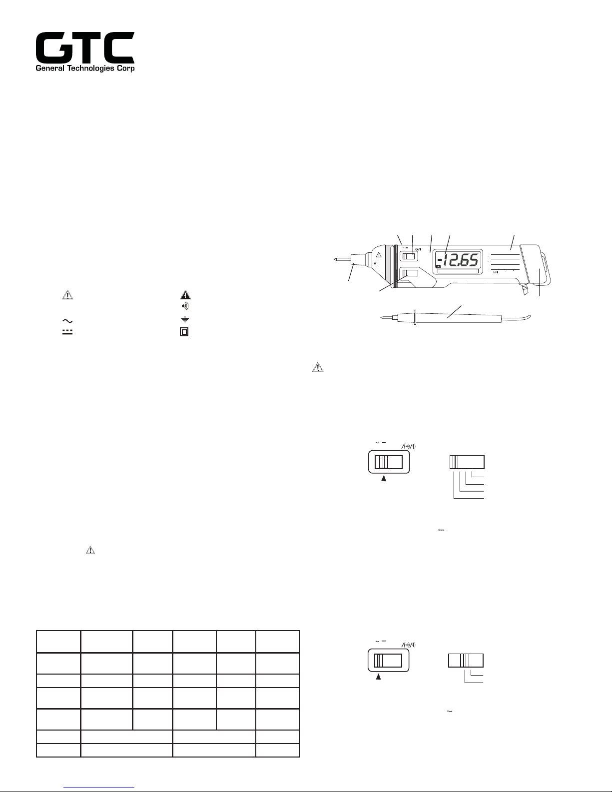
4.1 INSTRUMENT DESCRIPTION
1) Case
2) 3-1/2 Digit LCD display
3) Range switch
4) Function switch
5) Fixed test lead with probe
6) Fixed probe tip and fuse cap
7) Battery cover
8) Function / Range table
9) Display hold push button (back of the unit)
12
4
89
2. INTERNATIONAL SYMBOLS
Important information Dangerous Voltages
see manual
Continuity
AC Ground
DC Double Insulation
3. TECHNICAL SPECIFICATIONS
3.1 General Specifi cations
Display: 3-1/2 digits LCD, max. of 1999 display
Polarity: Automatic, (-) negative polarity indication
Zero adjustment: Automatic
Sample rate: 0.5 Sec.
Over range indication: Only the MSD “1” is displayed
Power: 9-volt battery type NEDA 1604, IEC6F22
Battery life: Approx. 50 hours. (w/ alkaline batteries)
Dimension: 141 x 69 x 36 mm.
Weight: Approx. 330g (including battery).
Accesories: User’s Manual, Alligator Clip, and 9V
alkaline battery
3.2 Electrical Specifi cations
The mark next to the probe tip, is a warning that the input
•
voltage should not exceed the indicated values. This is to prevent personal injuries and damage to the internal circuitry.
The function switches should be set to the function which you
•
want to test before operation.
Accuracies are ±(% of reading + number of least signifi cant
•
digits) at 23°C ±5°C, less than 75% RH.
Function Range Accuracy Input
DC Voltage 2000mV,20V,
AC Voltage 200V, 600V 1.5%+10 450 K
DC Current
Resistance
Diode Test
Continuity Beeps when < 100Ω 3VDC Max. Test Voltage 250 Vrms
200V, 600V
200 mA
2k, 20k,
200k,2000k
Test Current:1.0± 0.6mA Test Voltage: 3.2 V Max.
0.8%+1 1 M - 600 Vp-p
2.0%+2 - 200 mA/
1%+3 - - 250 Vp-p
Impedance
Remarks Overload
50~500Hz 600 Vp-p
Protection
250V Fuse
250 Vrms
6
3
5
7
4.2 Measurement Procedures
CAUTION: Maximum Input Voltage is 500Vrms,do not exceed
this rating to avoid personal injuries or damage to
the instrument. The range switch should be set to
the range you want to test before the operation.
4.2.1 DC Voltage measurement
600V
200V
20V
2000mV
FUNCTION RANGE
Set the FUNCTION switch to V and the RANGE switch to the
desired range position, according to the Function/Range Table.
Proceed to connect the test leads across the source or load under
measurement. If the voltage range is not known beforehand, set
the range switch to the highest range and work down. The polarity
will be indicated when the tip probe is connected.
4.2.2 AC Voltage measurement
600V
200V
FUNCTION RANGE
Set the FUNCTION switch to V and the RANGE switch to
desired position, according to the Function/Range Table.
Proceed to connect the test leads across the source or load under
measurement, and read the measurement on the LCD screen.
Page 2
4.2.3 DC Current measurement
V V mA
Ω
1 2 3 4
OFF
Ω
V V mA
Ω
1 2 3 4
OFF
Ω
V V mA
Ω
1 2 3 4
OFF
A
1 2 3 4
OFF
Ω
Ω
Ω
Ω
V V mA
Ω
200m
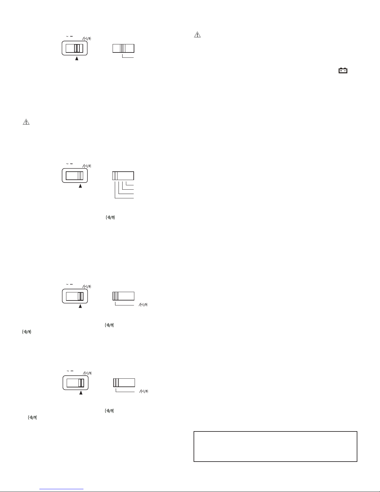
FUNCTION RANGE
Set the FUNCTION switch to mA and the RANGE switch to the
200mA position. Proceed to connect test leads IN SERIES with the
load in which current is to be measured, and read the measurement
on the LCD screen.
4.2.4 Resistance measurement
CAUTION: Maximum Input Voltage for these functions is 250
Vrms for less than 10 Sec., do not exceed this
rating to avoid personal injuries or damage to the
instrument. Also ensure there is no power applied
to the circuit and all capacitors are discharged.
5. MAINTENANCE
CAUTION: Before attempting battery removal or replacement,
disconnect test leads and remove the instrument
from any energized circuit to avoid shock hazard.
5.1 Battery Replacement
When the battery needs replacement, the battery symbol will
appear in the lower left hand side of the LCD display. To replace the
battery, remove the screw at the back Battery Cover and replace
with a new 9 V alkaline battery type NEDA 1604 or IEC6F22.
5.2 Fuse replacement
To replace the internal fuse, turn the Fuse Cap counter clockwise,
release the Fuse Cap assembly. Take out the blown fuse and replace
with a type IEC60127-2 or UL248-14 (5 x 20mm) fast acting fuse,
rated at 200mA/250V.
5.3 Cleaning
Periodically wipe the case with a soft damp cloth and mild household
cleanser. Do not use abrasives or solvents. Ensure that no water gets
inside the instrument to prevent possible shorts and damage.
2000K
200K
20K
2K
FUNCTION RANGE
Set the FUNCTION switch to /
and the RANGE switch to
desired k range, if the resistance being measured is connected to
a circuit, turn off power and discharge all capacitors before applying
probes.
Proceed to connect the test leads across the component or
circuit under test, and read the measurement on the LCD screen.
4.3 Other Functions
4.3.1 Diode test
FUNCTION RANGE
Set the FUNCTION switch to / , and RANGE switch to 2K/
position, Proceed to connect the test leads across the diode
observing the polarity: red probe to the anode (+) of the diode and
black test lead to the cathode (-).
4.3.2 Continuity Test
6. WARRANTY
One year limited warranty, excluding batteries and fuses. For details
see Standard Warranty Information in our webpage or you may request
a printed copy.
FUNCTION RANGE
Set the FUNCTION switch to / , and RANGE switch to 2K/
/ position, connect test leads across the circuit to be tested.
If resistance is less than approximately 100, the buzzer will be
activated.
4.3.3 Display Hold
A push button switch at the back of the unit is used to hold display
readings during measurements. Pressing and holding the button,
holds the display reading. Releasing the button will resume normal
operation.
General Technologies Corp.
#121 - 7350 72nd Street Tel.: (604) 952-6699
Delta, BC V4G 1H9 Fax: (604) 952-6690
Canada www.gtc.ca
© Copyright 2017 General Technologies
 Loading...