


Booster Power Supply
Manual
DEVELOPED BY
COPYRIGHT NOTICE
LIMITATION OF LIABILITY
FCC WARNING
COMPATIBLE DEVICES
General Signal Building Systems Corporation
6411 Parkland Drive
Sarasota, FL 34243
(941) 739-4300
Copyright © 1999 General Signal Building Systems Corporation
This manual and the products it describes are copyrighted by General Signal
Building Systems Corporation. You may not reproduce, translate, transcribe, or
transmit any part of this manual without express, written permission from
General Signal Building Systems Corporation.
This product has been designed to meet the requirements of NFPA Standard 72,
1996 Edition; Underwriters Laboratories, Inc., Standard 864, 7th Edition.
Installation in accordance with this manual, applicable codes, and the
instructions of the Authority Having Jurisdiction is mandatory. General Signal
Building Systems Corporation shall not under any circumstances be liable for
any incidental or consequential damages arising from loss of property or other
damages or losses owing to the failure of General Signal Building Systems
Corporation products beyond the cost of repair or replacement of any defective
products. General Signal Building Systems Corporation reserves the right to
make product improvements and change product specifications at any time.
While every precaution has been taken during the preparation of this manual to
ensure the accuracy of its contents, General Signal Building Systems
Corporation assumes no responsibility for errors or omissions.
This equipment can generate and radiate radio frequency energy. If this
equipment is not installed in accordance with this manual, it may cause
interference to radio communications. This equipment has been tested and
found to comply within the limits for Class A computing devices pursuant to
Subpart B of Part 15 of the FCC Rules. These rules are designed to provide
reasonable protection against such interference when this equipment is operated
in a commercial environment. Operation of this equipment is likely to cause
interference, in which case the user at his own expense, is required to take
whatever measures may be required to correct the interference.
For a complete list of compatible devices, refer to P/N 85000-0285.
DOCUMENT HISTORY: P/N 270946
Date Revision Reason for change
June 1999 1.0 Initial release.
July 1999 2.0 Added note to AC power wiring diagram and updated
specifications.
Technical Manuals Online! - http://www.tech-man.com

Introduction • 1
Models covered • 1
Description • 1
Specifications • 2
LED indicators • 2
Installing the enclosure • 3
Mounting Signature Series modules • 4
Configuring DIP switch setting options • 5
DIP switch configuration • 5
Jumper configuration • 7
Wiring the Booster Power Supply • 8
Wiring placement • 8
AC power wiring • 9
NAC Class B wiring • 9
NAC Class A wiring • 9
Trouble relay wiring • 10
Battery wiring • 10
Content
Applications • 11
NAC circuit power applications • 11
NAC applications using Signature Series modules • 13
Battery calculation worksheet • 15
24 Vdc Notification Appliance Circuit (NAC) specifications • 16
Technical Manuals Online! - http://www.tech-man.com

Introduction
Models covered
Catalog number Description
BPS6 6.5 Amp Booster Power Supply
BPS6220 6.5 Amp Booster Power Supply
BPS6C 6.5 Amp Booster Power Supply
MIRBPS6 6.5 Amp Booster Power Supply
MIRBPS6220 6.5 Amp Booster Power Supply
MIRBPS6C 6.5 Amp Booster Power Supply
XLS-BPS6 6.5 Amp Booster Power Supply
XLS-BPS6220 6.5 Amp Booster Power Supply
XLS-BPS6C 6.5 Amp Booster Power Supply
BPS10 10 Amp Booster Power Supply
BPS10220 10 Amp Booster Power Supply
BPS10C 10 Amp Booster Power Supply
MIRBPS10 10 Amp Booster Power Supply
MIRBPS10220 10 Amp Booster Power Supply
MIRBPS10C 10 Amp Booster Power Supply
XLS-BPS10 10 Amp Booster Power Supply
XLS-BPS10220 10 Amp Booster Power Supply
XLS-BPS10C 10 Amp Booster Power Supply
Description
The 10 Amp and 6.5 Amp Booster Power Supplies (BPS) are
designed to extend a fire alarm panel’s signaling capacity. The
Booster can be connected to existing Class A or Class B
Notification Appliance Circuits (NACs) or activated via
Signature Series modules. There are four independent 3.0 Amp
NAC circuits supervised in a non-alarm condition.
The Booster has a trouble relay that operates on any Booster
trouble. The Booster contains a battery charger capable of
charging up to two 10 amp hour, 12 V batteries to supply a total
of 24 Vdc.
Booster Power Supply Manual 1
Technical Manuals Online! - http://www.tech-man.com

Specifications
AC line voltage:
6.5 amp Booster
120 V / 220/240 Vac (50/60 Hz)
250 watts
10 amp Booster
Sense voltage V (input) 10 V – 45 V DC or 14 V - 32 V
Sense current I (input) 6 mA @ 24 Vdc, 3 mA @ 12 Vdc,
NAC output voltage 24 V nominal (special application output
NAC output current 3.0 A max. per circuit, 10 A/6.5 A
Wire size 18 - 12 AWG
NAC EOL
Auxiliary supv. current 6 amps max. (3 amps max./circuit)
Auxiliary outputs 2 (programmable), replaces NACs
Auxiliary outputs disabled
under battery
Battery Requirements Up to 10 AH
Battery charger current limit 1.0 A max.
Operating environment:
Operating temperature
Operating humidity
120 V / 220/240 Vac (50/60 Hz)
375 watts
FWR (unfiltered DC)
12 mA @ 45 Vdc
use only)
max total all NACs
15 KΩ
Optional – programmable after 30
seconds
O
32 to 120
0 to 93% RH
F (0 to 49O C)
LED indicators
The Booster has six LED indicators. There are four NAC trouble
LEDs, one battery trouble LED, and one ground fault LED.
2 Booster Power Supply Manual
Technical Manuals Online! - http://www.tech-man.com

Installing the enclosure
Be sure to follow all applicable national (NFPA 72) and local
fire alarm codes and standards when installing this system.
Mount the backbox at the required location. A dedicated 120
Vac (220/240 Vac) 50/60 Hz circuit is required for power.
Install all conduit and pull all wiring into the backbox before
proceeding.
13.00" (33.02 cm)
3.375" (8.6 cm)
3.50" (8.9 cm) 3.50" (8.9 cm)
Side View
17.00" (43.2 cm)
17.00" (43.2 cm)
To p Vi e w
13.00" (33.02 cm)
7.00" (17.78 cm)
Front View
All knockouts
for 3/4" conduit
(1.9 cm)
Side View
[Backbox.cdr]
17.00" (43.2 cm)
Booster Power Supply Manual 3
Technical Manuals Online! - http://www.tech-man.com

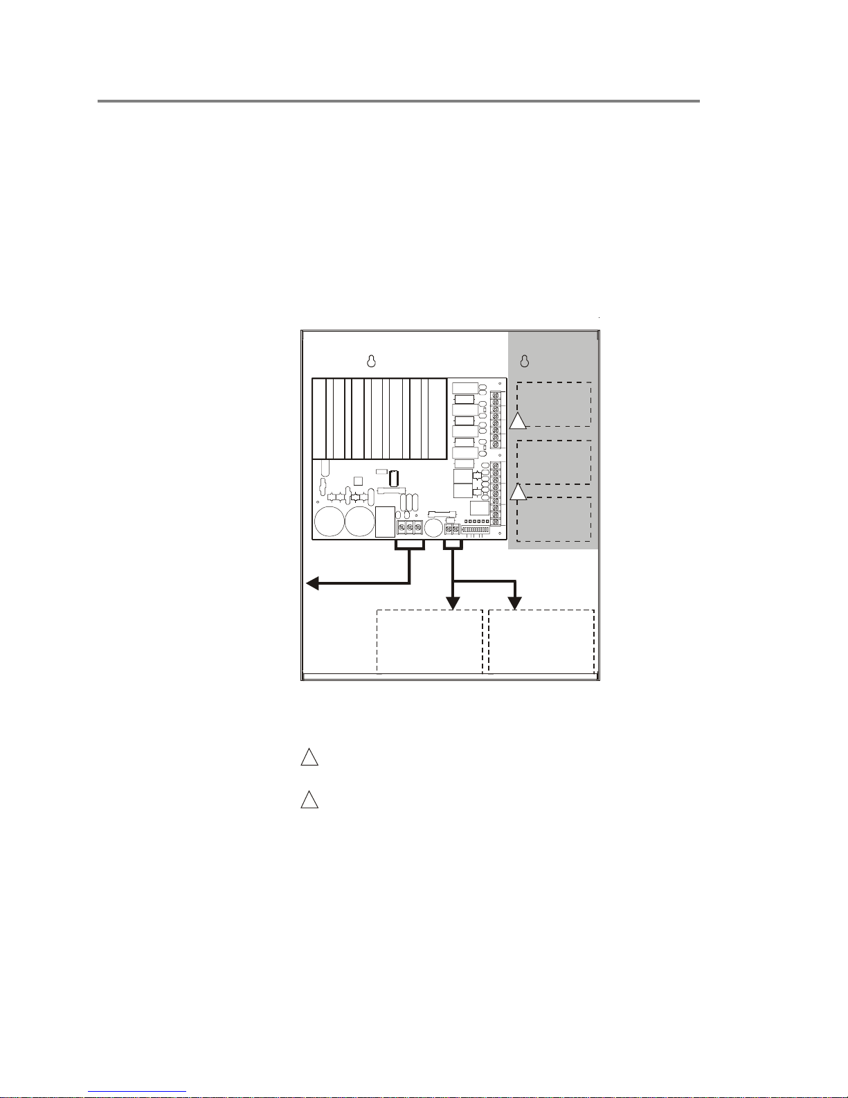
Mounting Signature Series modules
To mount Signature Series modules:
1. Remove the black bracket connected to the module.
2. Snap the module in one of the three provided brackets in the
backbox.
Refer to the drawing below.
Booster Power Supply
1
P3
LNG
Backbox
P4
+BATTERY-
NAC1
NAC2
NAC3
SW1
123456789101112
ABRATEAC AUX
S1 S2
+
NAC1
+-
NAC2
+-
NAC3
+-
NAC4
-
P1
COM IN
SENSE 1
COM IN OUT
SENSE 2
OUT
COM N O
TROUBLE
BAT
NAC4
GND
NC
P2
SW1
Mounting brackets
Signature module
Signature module
6
5
10
10
483726
48372
TB3
9
15
TB1
TB3
9
1
TB1
Battery Battery
[MODMOUNT.cdr]
4 Booster Power Supply Manual
Technical Manuals Online! - http://www.tech-man.com

Configuring DIP switch setting options
DIP switch configuration
A 12-position DIP switch is used to configure NAC circuit
options, AC power loss, auxiliary outputs, and Class A or B
wiring. The following tables show the positions for each switch
on the DIP switch for the various input, output, and panel
configurations.
SW1
ON
1
23456789101112
S2
RATE
AB
2 only
& 3 only
S1
Sense 1 input
Switch SW1-1/2 (S1)
SW1-1 SW1-2 Class B Class A
OFF OFF Activates all NACs Activates both NACs
ON OFF Activates NAC1 only Activates NAC 1/2
OFF ON Activates NACs 1 &
ON ON Activates NACs 1, 2
AC
AUX
[Switch.CDR]
Description
1/2 and 3/4
Activates NAC 1/2
Activates both NACs
1/2 and 3/4
Sense 2 input
Switch SW1-3/4 (S2)
Description
SW1-3 SW1-4 Class B
OFF OFF Activates all NACs Activates both NACs
ON OFF Activates NACs 2, 3,
& 4 only
OFF ON Activates NACs 3 &
4 only
ON ON Activates NAC4 only No NACs activated
Class A or B configuration
Switch SW1-5 (AB)
SW1-5 Description
ON NACs Class A (JP1 and JP2 must be set to Class A)
OFF NACs Class B (JP1 and JP2 must be set to Class B)
Booster Power Supply Manual 5
Class A
1/2 and 3/4
Activates NAC 3/4
Activates NAC 3/4
Technical Manuals Online! - http://www.tech-man.com

NAC output rate
Switch SW1-6/7/8 (RATE)
SW1-6 SW1-7 SW1-8 Description
OFF OFF OFF All NACs follow sense input
ON OFF OFF NAC1 is Temporal [3-3-3], all
others follow sense input
OFF ON OFF NAC1 & 2 are Temporal [3-3-3],
all others follow sense input
ON ON OFF NAC1, 2, & 3 are Temporal
[3-3-3], NAC4 follow sense input
OFF OFF ON All NACs are Temporal [3-3-3]
ON OFF ON All NACs are 120 bpm
OFF ON ON NAC1 & 2 are 120 bpm, NAC3 &
4 follow sense input
ON ON ON NACs 1, 2, & 3 are 120 bpm,
NAC4 follow sense input
AC power
Switch SW1-9 (AC)
SW1-9 Description
ON AC power loss reporting delay is 6 hours
OFF AC power loss is reported within 20 seconds
Auxiliary output setup
Switch SW1-10 (AUX)
SW1-10 Description
ON NAC3 configured as an auxiliary output
OFF NAC3 configured as NAC output circuit
Switch SW1-11 (AUX)
SW1-11 Description
ON NAC4 configured as an auxiliary output
OFF NAC4 configured as NAC output circuit
Switch SW1-12 (AUX)
SW1-12 Description
ON Auxiliary outputs turn off 30 seconds after AC fail
OFF Auxiliary outputs stay on after AC fail
6 Booster Power Supply Manual
Technical Manuals Online! - http://www.tech-man.com

Jumper configuration
JP1 and JP2 are used to select a Class A or Class B NAC wiring
configuration. Both jumpers must be positioned to match the
SW1-5 DIP switch selection (Class A or Class B).
11
22
33
JP1 JP2
Class A Class A
Class B Class B
[Jumper.CDR]
Booster Power Supply Manual 7
Technical Manuals Online! - http://www.tech-man.com
Wiring the Booster Power Supply
Wiring placement
To avoid noise, keep input wiring isolated from high current
output and power limited wiring. Separate high current
input/output from low current. Separate power limited from nonpower limited wiring.
Wiring within the cabinet should be routed around the cabinet,
not across the printed circuit board.
Backbox
power limited
wiring area
Booster Power Supply
+
NAC1
Signature
+-
1
P1
BAT
NAC1
NAC2
NAC3
NAC4
GND
SW1
P2
P3
LNG
+BATTERY-
P4
123456789101112
ABRATEAC AUX
S1 S2
SW1
NAC2
+-
NAC3
+-
NAC4
-
COM IN
SENSE 1
COM IN OUT
SENSE 2
COM NO OUT
TROUBLE
NC
2
3
Module
Signature
Module
Signature
Module
Route AC supply
through these
knockouts only
Battery wiring (non-power
limited & supervised)
(non-power limited &
supervised)
Battery
Battery
[Wire route.cdr]
Notes:
1. Maintain 1/4 in. (6 mm) spacing between power limited
and non-power limited wiring or use type FPL, FPLR,
or FPLP cable per NEC.
2 Power limited and supervised when configured as
auxiliary power.
auxiliary power
Non-supervised when configured as
.
not
3 Source must be power limited. Source determines
supervision.
4. When using larger batteries, make sure to position the
battery terminals towards the door.
8 Booster Power Supply Manual
Technical Manuals Online! - http://www.tech-man.com

AC power wiring
Booster Power
Supply Main Board
Battery
+
P3
LNG
To dedicated 120 VAC
50/60 Hz branch circuit
50/60 Hz branch circuit
or
220/230/240 VAC
(-220 models only)
-
P4
[Power.CDR]
250 watts for 6.5 amp Booster
375 watts for 10 amp Booster
NAC Class B wiring
Per the NEC, no field wiring can
have a potential greater than 150 Vac
with respect to earth ground.
Note 1: A trouble on the
Booster will be sensed on the
existing fire panels NAC circuit
causing an NAC trouble on that
panel.
In an alarm condition, the
Booster will allow NAC current
to move downstream to
devices connected to the
existing fire panel’s NAC
circuit.
Note 2: Refer to the connected
fire alarm control panel’s
documentation for more details
on making NAC wiring
connections.
Sense 1
Sense 2
Trouble
Battery
+
-
NAC1
NAC2
NAC3
NAC4
COM
OUT
COM
OUT
COM
[NAC Class B.CDR]
Booster Power
Supply Main Board
P3
LNG
P4
NAC Class A wiring
Sense 1
Sense 2
Trouble
Battery
+
-
[NAC Class A.CDR]
NAC1
NAC2
NAC3
NAC4
COM
OUT
COM
OUT
COM
Booster Power
Supply Main Board
P3
LNG
P4
NO
NC
NO
NC
Notification Appliance Circuit (NAC)
+
+++
1
Notification Appliance Circuit (NAC)
1
P1
IN
IN
++
To next signaling
2
P2
device or NAC
end-of-line resistor
NOTES:
1
Used for another Class B NAC circuit.
2
Used to connect another input circuit
UL Listed
EOL 15 K
UL Listed
EOL 15 K
NAC
Existing fire
alarm panel
notification
circuit
or signaling device.
++++
P1
IN
IN
++
To next signaling
1
P2
device or NAC
returning to existing
fire alarm panel
NOTES:
1
Used to connect another input circuit
or signaling d evice.
Notification
Appliance
Circuit (NAC)
Notification
Appliance
Circuit (NAC)
NAC
Existing fire
alarm panel
notification
circuit
Booster Power Supply Manual 9
Technical Manuals Online! - http://www.tech-man.com
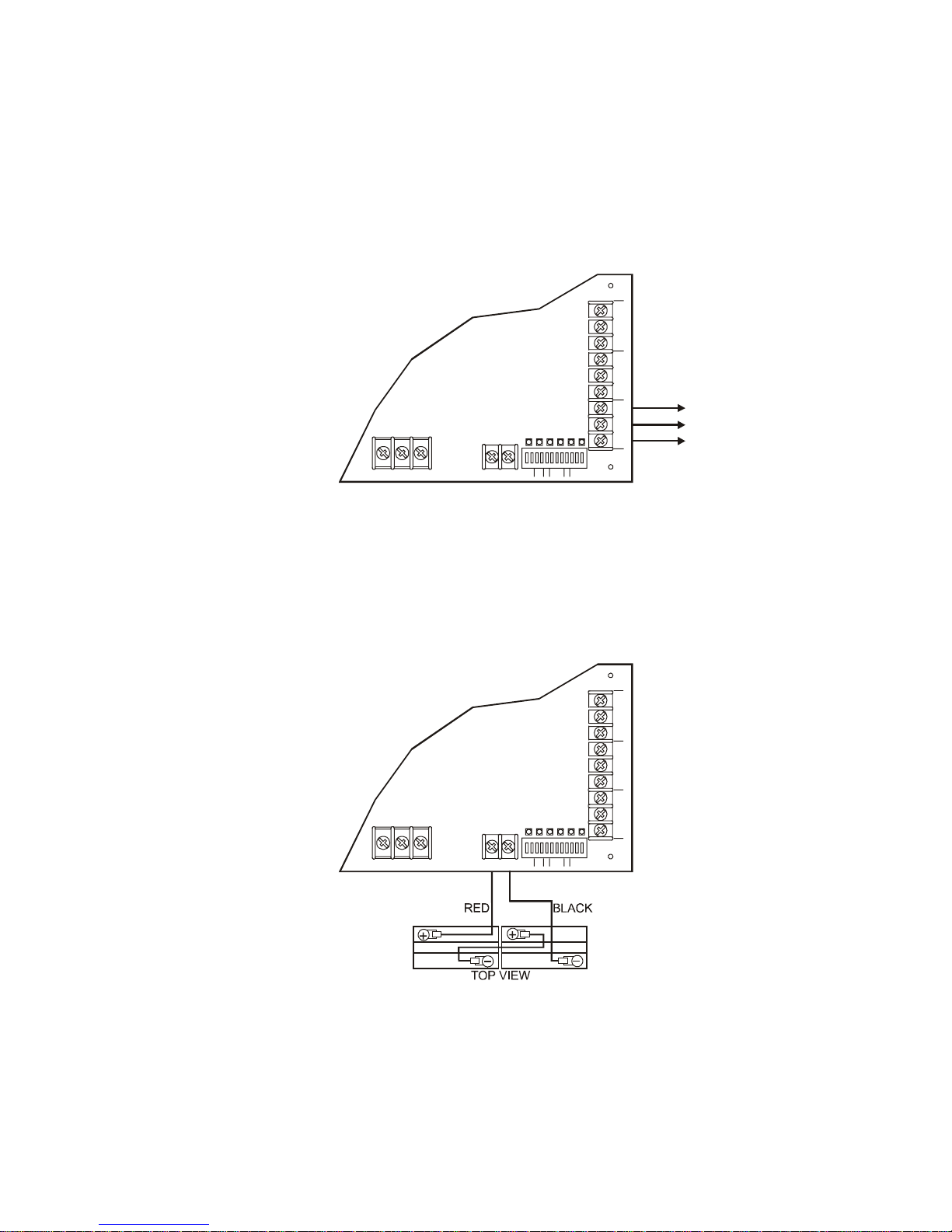
Trouble relay wiring
The Booster Power Supply has a Form C trouble relay that
provides a normally open and normally closed contact. The
trouble relay will deactivate under any trouble condition. A
16-second delay is used on the trouble relay for AC fail and
brownout troubles.
COM IN
SENSE 1
Booster Power Supply
LNG
P3
[Trouble.CDR]
Main Board
BATTERY
+
P4
1
-
NAC1
NAC2
NAC3
NAC4
23456789101112
RATEACAUX
S1
S2
AB
COM IN OUT
SENSE 2
OUT
COM NO
BAT
GND
NC
TROUBLE
P2
SW1
To Booster trouble
monitoring device
Battery wiring
Two backup batteries are required with the Booster Power
Supply. Use 12 Vdc, up to 10 AH batteries. Batteries should be
replaced every five years. The diagram below depicts proper
battery wiring.
COM IN
SENSE 1
Booster Power Supply
LNG
P3
[Battery.CDR]
Main Board
BATTERY
+
P4
NAC1
123456 789101112
S1 S2
-
NAC2
NAC3
NAC4
AUX
RATE
AB
AC
COM IN OUT
SENSE 2
COM NO OUT
BAT
GND
NC
TROUBLE
P2
SW1
10 Booster Power Supply Manual
Technical Manuals Online! - http://www.tech-man.com
Applications
g
g
g
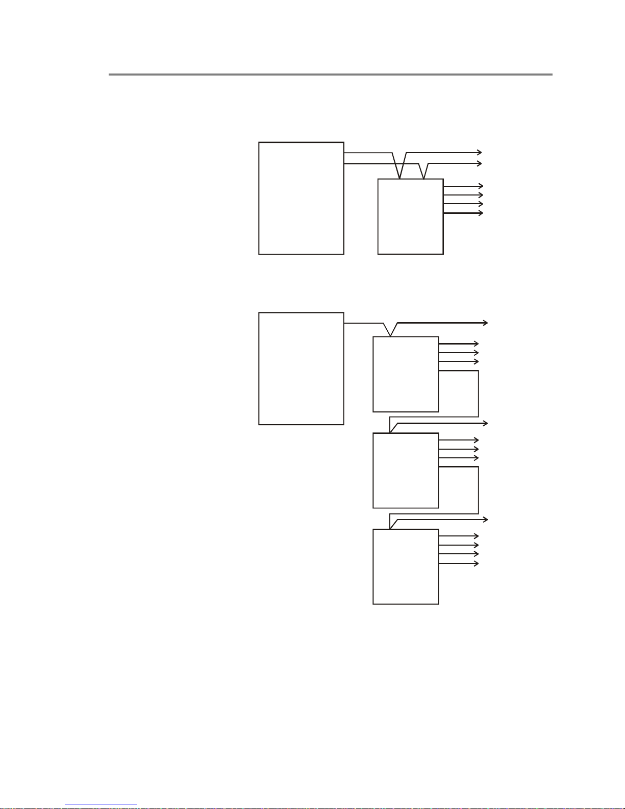
NAC circuit power applications
NAC Circuit
NAC Circuit
Sense 1 Input
Sense 2 Input
Fire Alarm
Control Panel
Booster Power
Supply
[APP-01.CDR]
Inputs activate NAC outputs based on programming
NAC Circuit
Sense 1 Input Sense 1 Input Sense 1 Input
Fire Alarm
Control Panel
NAC output #1
NAC output #2
NAC output #3
NAC output #4
Booster Power
Supply
[APP-03.CDR]
NAC output #1
NAC output #2
NAC output #3
NAC output #4
To n ex t s i
device, booster, or
EOL resistor
NAC output #1
NAC output #2
NAC output #3
NAC output #4
To n ex t s ignalin
device, booster, or
EOL resistor
To next signaling
device, booster, or
EOL resistor
nalin
Booster Power
Supply
To next signaling
device, booster, or
EOL resistor
NAC output #1
NAC output #2
NAC output #3
NAC output #4
Booster Power
Supply
One fire alarm control panel activating three Boosters in series
Booster Power Supply Manual 11
Technical Manuals Online! - http://www.tech-man.com

NAC Circuit
g
g
g
Sense 1 Input Sense 1 Input
Fire Alarm
Control Panel
Booster Power
Supply
NAC Circuit
[APP-02.CDR]
Booster Power
Supply
One fire alarm control panel activating two Boosters
To n ex t s ignalin
device, booster, or
EOL resistor
NAC output #1
NAC output #2
NAC output #3
NAC output #4
To next signaling
device, booster, or
EOL resistor
NAC output #1
NAC output #2
NAC output #3
NAC output #4
Fire Alarm
Control Panel
[APP-04.CDR]
NAC Circuit
NAC Circuit
Sense 1 Input
Booster Power
Supply
Sense 1 Input
Sense 2 Input
Booster Power
Supply
Sense 1 Input
To n ex t s i
device, booster, or
EOL resistor
To next signaling
device, booster, or
EOL resistor
nalin
NAC output #4
To next signaling
device, booster, or
EOL resistor
NAC output #1
NAC output #2
NAC output #3
NAC output #4
All 5 outputs activate when
input NAC #1 activates
(based on progr amming)
NAC output #1
NAC output #2
NAC output #3
All 5 outputs activate when
input NAC #2 activates
(based on progr amming)
NAC output #1
NAC output #2
NAC output #3
NAC output #4
Booster Power
Supply
Each fire alarm control panel NAC activates five output circuits
12 Booster Power Supply Manual
Technical Manuals Online! - http://www.tech-man.com

NAC applications using Signature Series modules
Note: These applications
show Signature Series CC1
module connections.
However, other Signature
Series signal modules can
be used. A maximum of 10
modules are allowed per
NAC. The maximum total
for parallel EOL’s is 4.7 K.
Notification Appl iance Circuit (NAC)
Booster Power
Supply Main Board
P3
LNG
P4
Sense 1
Sense 2
Trouble
Battery
+
-
NAC1
NAC2
NAC3/
AUX1
NAC4/
AUX2
IN
COM
OUT
IN
COM
OUT
NO
COM
NC
[APP-05.CDR]
++++
1
Notification Appl iance Circuit (NAC)
P1
2
+
EOL 47 K
P2
++++
3
6
5
10
9
CC1
Module
48372
UL Listed
EOL 15 K
UL Listed
EOL 15 K
1
NOTES:
Used for another Class B NAC circuit.
NAC4 is configured as an auxiliary output.
Data in from previous
device or Signature
controller
Data out to
next device
CC1 wiring must be within 3 feet of the Booster wiring and in conduit or mounted within
the Booster's enclosure.
Any Booster trouble will cause the CC1 supervisio n to report a trouble to the main fire
panel.
Booster Power
Supply Main Board
NAC3/
AUX1
NAC4/
AUX2
Sense 1
Sense 2
Trouble
Battery
+
P3
LNG
[APP-06.CDR]
NOTES:
1
Used for another Class B NAC
circuit.
2.
Any Booster trouble will cause the
CC1 supervision to report a trouble
to the main f ire panel.
3
Modules must be wired and
programmed on the Signature
controller for proper operation.
-
P4
NAC1
NAC2
COM
OUT
COM
OUT
COM
IN
IN
NO
NC
Notification Appliance Circuit (NAC)
++++
1
1
Notification Appliance Circuit (NAC)
1
P1
+
+
EOL 47 K
P2
++
10
9
CC1
Module
+
Riser in
12 - 24 Vdc
48372
6
5
1
UL Listed
EOL 15 K
UL Listed
EOL 15 K
10
9
CC1
Module
+++
48372
6
5
33
Riser out to next
device or riser
supervisory device
1
Booster Power Supply Manual 13
Technical Manuals Online! - http://www.tech-man.com

Sense 1
Sense 2
Trouble
Battery
+
-
NAC1
NAC2
NAC3/
AUX1
NAC4/
AUX2
COM
COM
COM
OUT
OUT
Booster Power
Supply Main Board
P3
LNG
[APP-07.CDR]
NOTES:
1
Used for another Class B NAC circuit.
2
When a BPS output is programmed as
an AUX output, an EOL relay MUST b e
used to supervise the AUX output.
P4
NO
NC
NAC Circuit
++++
11
1
P1
IN
IN
+
+
P2
Out to EOL
or next device
CC1
Module
+
+
5
6
7
8
Data in from
previous device or
Signature controller
UL Listed
EOL 15 K
From existing fire alarm
panel notification circuit
or CC1 module
NAC Circuit
+
9
10
+
+
1
2
3
4
Data out to
next device
NAC Circuit
UL
Listed
EOL
47 K
UL
Listed
EOL
47 K
+
9
10
CC1
Module
+
7
8
+
+
5
6
+
1
2
3
4
EOL
15 K
Data in from
2
previous device or
Signature controller
EOL
relay
CT1
Module
Data in from fire
alarm control panel
Data out to
next device
Data out to
next device
14 Booster Power Supply Manual
Technical Manuals Online! - http://www.tech-man.com

Battery calculation worksheet
Auxiliary devices
Note: Only add auxiliary current if SW1-12 is OFF. (Auxiliary output stays on after AC power failure.
Device type Quantity Auxiliary current (mA) Total / device
Total Aux.
A (mA)
NAC devices
Note: Use strobe 20.4 V current rating for calculations.
Device type Qty Alarm current (mA) Total alarm
Total NAC Alarm Current B (mA)
Supervisory Current Calculation
Supervisory current 70 + A (if SW1-12 = OFF) = (mA)
Supervisory Hours (i.e. 24,60) X (Hr)
Supervisory battery required (mAHr) = C (mAHr)
Alarm Current Calculation
Alarm Minutes (i.e. 5 min.) = D (min)
Alarm Hours (D/60) = E (Hr)
Alarm current 190 + A (if SW1-12 = OFF) + B = (mA)
Alarm Hours X E (Hr)
Alarm battery required (mAHr) = F (mAHr)
Total Battery Requirement
Total Amp-Hour Battery Size [(1.11 x C) + (2 x F)] =
Booster Power Supply Manual 15
Technical Manuals Online! - http://www.tech-man.com
10 AH Max.
1000

24 Vdc Notification Appliance Circuit (NAC) specifications
The NAC cable must be a minimum 18 gauge. Distance limits
are determined using the maximum allowable circuit resistance
and cable manufacturer's specifications. Restrictions apply when
Note: No "T" tapping
permitted.
calculating the wire size for the NACs:
1. Minimum supply voltage available is 18.9 V.
2. Minimum required circuit voltage at any NAC is 17 Vdc.
3. Maximum alarm current required for all NACs.
Typical cable pair resistances
Wire size Resistance per
12 AWG
14 AWG
16 AWG
18 AWG
1,000 feet
3.5 Ω
5.2 Ω
8.0 Ω
13.0 Ω
Using Ohm's law, the NAC current requirement, and a voltage
drop of 1.9 volts (18.9 - 17), the maximum allowable NAC
resistance is determined as follows:
V
R
max
I
drop
= ------- I
max
R
= Maximum allowable NAC resistance
max
= Maximum NAC current requirement
max
V
= Maximum allowable voltage drop
drop
from power supply to NAC
Using this formula, the maximum permissible circuit resistance
for a loaded (2.5 A) circuit is 0.76 9 as follows:
1.9 V
0.76 Ω = -------
2.5 A
Using the Load vs. Distance table, the maximum allowable length
(D) of any listed wire gauge pair is determined as follows:
R
max
D = ------- X 1000 R
R
/1000'PAIR
D = Distance in feet
=Maximum allowable wire resistance
max
R
/1000' PAIR
= wire resistance per 1000' pair
Using this formula, the maximum length of a loaded (2.5 A) NAC
using a pair of 14 AWG wires is:
0.76
146.1' = ------- X 1000
5.2
146 feet is the maximum length of a loaded (2.5 A) NAC branch
circuit using a pair of 14 AWG wires.
Quick reference table (load vs. distance NAC circuit (1.9 volt drop))
Load Maximum distance to last appliance, in feet (meters)
current 12 AWG 14 AWG 16 AWG 18 AWG
0.1 A 5,428 (1656) 3,654 (1114) 2,375 (724) 1,461 (446)
0.25 A 2,171 (662) 1,461 (446) 950 (290) 585 (178)
0.50 A 1,086 (331) 731 (223) 475 (145) 292 (89)
0.75 A 714 (218) 487 (148) 312 (95) 192 (58)
1.0 A 543 (165) 365 (111) 237 (72) 146 (44)
1.5 A 360 (110) 243 (74) 157 (48) 97 (29)
2.0 A 271 (83) 183 (56) 119 (36) 73 (22)
2.5 A 217 (66) 146 (44) 95 (29) 58 (18)
3.0 A 180 (55) 122 (37) 79 (24) 48 (15)
16 Booster Power Supply Manual
Technical Manuals Online! - http://www.tech-man.com
 Loading...