

OPERATING INSTRUCTIONS
TYPE
INDUCTANCE
1632-A
BRIDGE
GENERAL
c
RADIO
COMPANY
GENERAL
RADIO
COMPANY
WEST
EMerson
9-4400
DISTRICT
NEW
YORK
Broad
Telephone N.Y.
Ave.
at
N.J. WHitney
Linden, Ridgefield,
WOrth
SYRACUSE
Pickard Bldg.
East Molloy Rd., Syracuse 11,
Telephone GLenview
PHILADELPHIA
1150
York Rd., Abington, Penna.
Telephone TUrner
Philo., HAncock
4-7
WASHINGTON
Rockville Pike
Telephone
at
Wall Lane, Rockville, Md.
946-1600
FLORIDA
113
East Colonial Drive, Orlando,
Telephone
GArden
CHICAGO
6605
West
North
Telephone Vlffage
LOS
SAN
ANGELES
1000
N.
Seward
Telephone
HOllywood 9-6201
St.,
FRANCISCO
1186
Los
Altos
Ave.,
Telephone WHitecliff
CANADA
99
Floral Pkwy., Toronto
Telephone CHerry 6-2171
OFFICES
4-2722
3-3140
4-9323
7-8486
419
5-4671
Ave
.,
Oak
8-9400
Los
Angeles
Los
Altos, Calif.
8-8233
15,
CONCORD,
N.
J.
N.Y.
Fla.
Park,
Iff.
38,
Calif.
Ont.
MASSACHUSETTS
REPAIR
EAST
General Radio
Service Department
22
Baker
Telephone EMerson
NEW
General Radio Company
Service Department
Broad Ave.
Telephone N.Y. WOrth
WASHINGTON
General Radio Company
Service Department
Rockville Pike
T~lephone
MIDWEST
General Radio Company
Service Department
6605
Telephone VIllage
WEST
General Radio Company
Service Department
1
000
Los
Angeles
Telephone HOllywood
CANADA
General Radio Company
Service Department
99
Floral Pkwy., Toronto
Telephone CHerry 6-2171
Mission
COAST
Ave.,
YORK
at
Linden, Ridgefield,
N.J. WHitney
at
946-1600
West
North
COAST
N.
Seward
38,
6-7400
SERVICES
Company
W.
Concord, Mass.
9-4400
N.J.
4-2722
3-3140
Wall Lane, Rockville, Md.
Ave.,
Oak
Park,
Iff.
8-9400
St.
Calif.
9-6201
15,
Ont.
General Radio Company (Overseas),
Representatives
in
Principal Overseas Countries
Zurich, Switzerland
Printed
in USA
OPERATING INSTRUCTIONS
TYPE
INDUCTANCE
1632-A
BRIDGE
Form
1632-0100-C
September,
1962
GENERAL
WEST
CONCORD,
RADIO
MASSACHUSETTS,
COMPANY
USA
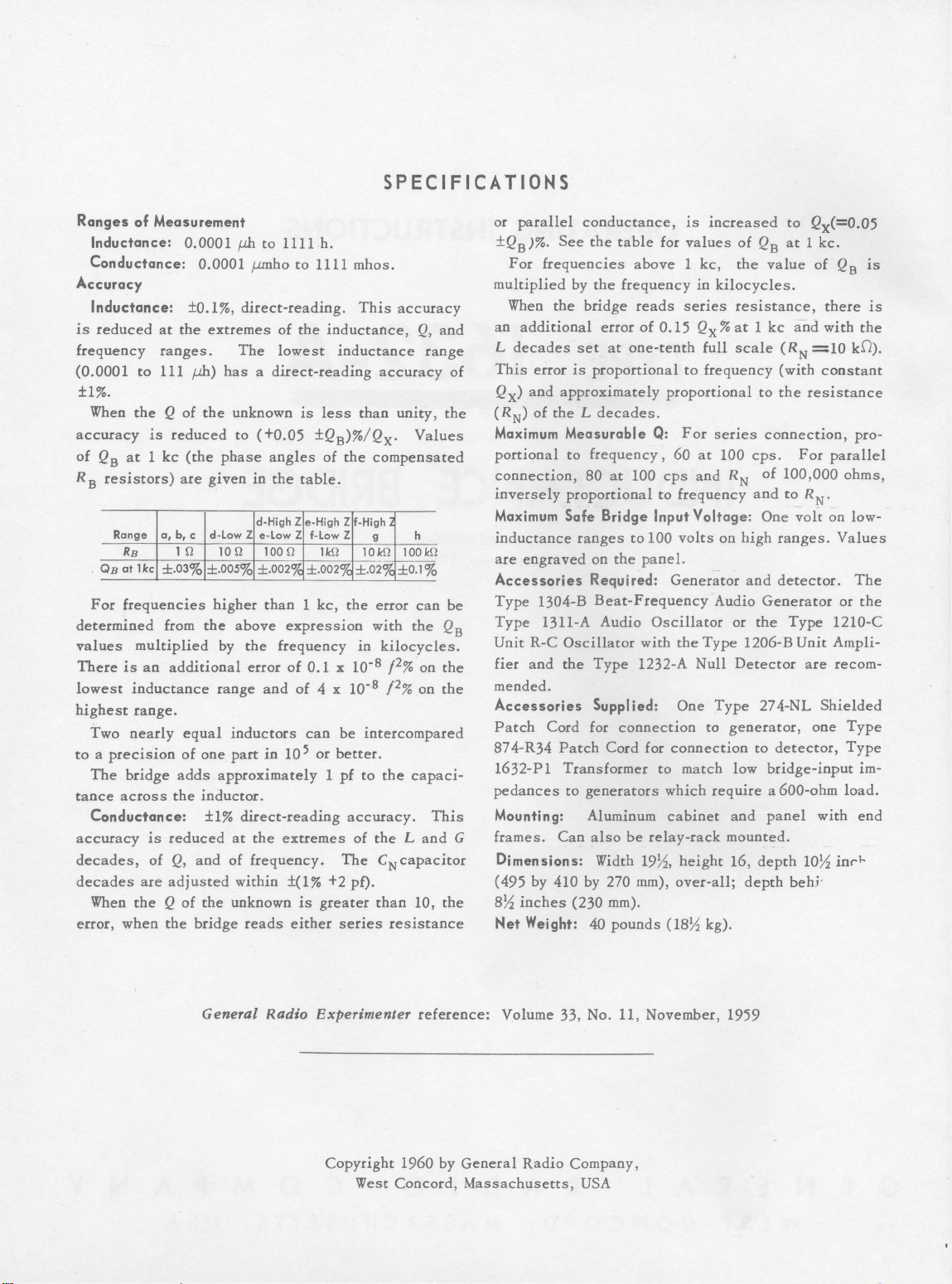
SPECIFICATIONS
Ranges
Accuracy
is
frequency
(0.000 1 to
of
Measurement
Inductance:
Conductance:
Inductance:
reduced
at
ranges.
111 /)ll)
±1%.
When
the
accuracy
of
RB
For
determined
values
There
lowest
highest
Two
to a precision
The
tance
Conductance:
accuracy
decades,
decades
When
error,
QB
at 1 kc
resistors)
Range
RB
QB
at
1kc
frequencies
multiplied
is
an
inductance
range.
nearly
bridge
across
are
the Q of
when
is
a,
is
of
0.0001
0.0001
±0.1%,
the
extremes
has a direct-reading
Q of
the
unknown
reduced
(the
phase
are
given
b, c
d-law Z e-law Z f-law
1
fl
10
±.03%
±.005%
higher
from
the
by
additional
range
equal
inductors
of
one
part
adds
approximately 1 pf
the
inductor.
±1%
reduced
Q,
and
at
of
adjusted
the
unknown
the
bridge
iJl!
to
1111 h.
f-LII1ho
to 1111
direct-reading.
of
the
The
lowest
is
to
(+0.05
angles
in
the
table.
d-High Z
fl
100
fl
±.002%
than 1 kc,
above
the
error
and
in
expression
frequency
of
of
10 5
mhos.
This
inductance,
inductance
less
than
±QB)%/Qx.
of
the
e-High Z f-High
Z
1
kfl
10
±.002%
±.o2%
the
in
0.1 x 10·
4 x
10·
can
be
or
better.
to
direct-reading
the
extremes
frequency.
accuracy.
of
The
within ±(1% +2 pf).
is
greater
reads
either
series
accuracy
Q,
and
range
accuracy
unity,
of
the
Values
compensated
g
h
kfl
100
kfl
1--
--
±0.1%
error
can
be
with
the
QB
kilocycles.
2
8
/
% on
the
8
f2%
on
the
intercompared
the
capaci-
This
the L and
CNcapacitor
than
10,
the
resistance
or
parallel
±QB
)%.
For
multiplied
When
an
additional
L
decades
This
Qx)
and
(RN)
Maximum Measurable
portional
connection,
inversely
Maximum Safe Bridge Input Voltage: One
inductance
are
engraved
Accessories Required:
Type
Type
Unit
R-C
fier
and
conductance,
See
the
frequencies
by
the
the
bridge
error
set
at
error
is
proportional
approximately
of
the L decades.
to
frequency,
80
at
proportional
ranges
on
the
1304-B
Beat-Frequency
1311-A Audio
Oscillator
the
Type
table
for
above 1 kc,
frequency
reads
of
0.15
one-tenth
proportional
Q:
60
100
cps
to
to
100
panel.
Gener~tor
Oscillator
with
1232-A
is
values
in
series
Qx%
to
For
at
and
frequency
volts
the
Null
mended.
Accessories Supplied:
Patch
874-R34
1632-P1
pedances
Mounting: Aluminum
frames.
G
Dimensions: Width
Cord for
Patch
Transformer
to
Can
(495 by 410 by 270 mm),
8~
inches
Net
(230
Weight: 40
connection
Cord for
generators
also
be
mm).
pounds
One
connection
to
match
which
cabinet
relay-rack
19~,
height
over-all;
(
18~
increased
of
the
kilocycles.
resistance,
at 1 kc
full
scale
frequency
series
100
cps.
RN
and
on
high
and
Audio
or
the
Type
1206-B
Detector
Type
to
generator,
to
low
require
and
mounted.
16,
depth
depth
kg).
to
Qx(=0.05
QB
at 1 kc.
value
of
and
with
(RN
=10
(with
constant
to
the
resistance
connection,
For
of
100,000
to
Rw
voft
ranges.
detector.
Generator
Type
Unit
are
27 4-NL
Shielded
one
detector,
bridge-input
a 600-ohm
panel
with
10~
behj·
QB
there
the
kD).
pro-
parallel
ohms,
on low-
Values
The
or
the
1210-C
Ampli-
recom-
Type
Type
im-
load.
end
inrl--
is
is
General
Radio
Experimenter
Copyright
West
Concord,
reference:
1960 by
Volume 33, No. 11, November,
General
Massachusetts,
Radio
Company,
USA
1959
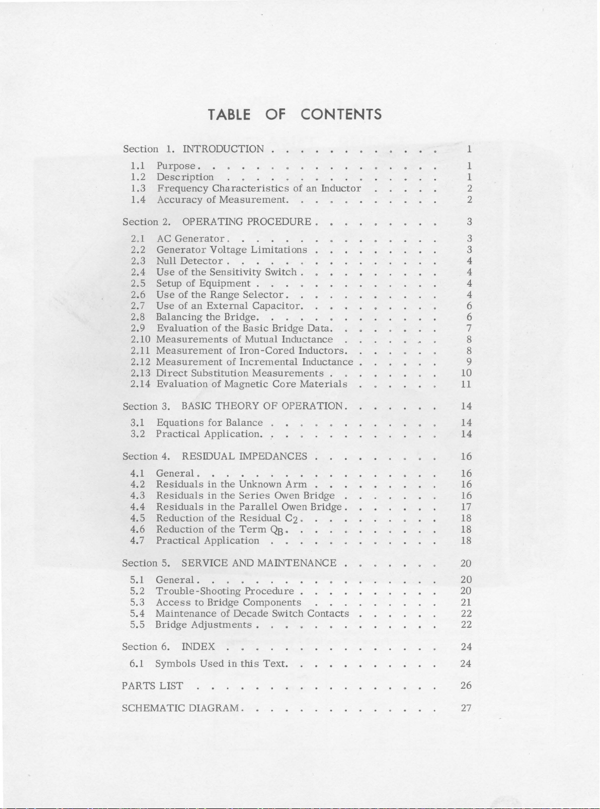
TABLE
OF
CONTENTS
Section
1.1
1.2
1.3
1.4
Section
2.1
2.2
2o3
2.4
2.5
2.6
2.7
2.8
2.9
2.10
2.11
2.12
2.13
2.14
Section
3.1
3.2
1.
INTRODUCTION
Purpose
Description
Frequency
Accuracy
2.
AC
Generator
Null
Use
Setup
Use
Use
Balancing
Evaluation
Measurements
Measurement
Measurement
Direct
Evaluation
3. BASIC
Equations
Practical
.
Characteristics
of
OPERATING
Generator
Voltage
Detector
of
the
Sensitivity
of
Equipment
of
the
Range
of
an
External
the
of
Substitution
of
for
Application.
Measurement.
PROCEDURE
0
Limitations
.
Switch
.
Selector.
Capacitor.
Bridge.
the
Basic
of
Mutual
of
Iron
-Cored
of
Incremental
Measurements
Magnetic
THEORY
Balance
OF
of
an
o
.
Bridge
Core
.
Data.
Inductance
Inductors.
Inductance
Materials
OPERATION.
Inductor
.
1
1
1
2
2
3
3
3
4
4
4
4
6
6
7
8
8
9
10
11
14
14
14
Section
4.1
4.2
4.3
4.4
4. 5
4.6
4. 7 Practical
Section
5.1
5.2
5.3
5.4
5.5
Section
6.1
PARTS
SCHEMATIC
4.
General,
Residuals
Residuals
Residuals
Reduction
Reduction
5.
General.
Trouble-Shooting
Access
Maintenance
Bridge
6.
Symbols
LIST
RESIDUAL
in
the
in
the
in
the
of
the
of
the
Application
SERVICE
to
Bridge
of
Adjustments
INDEX
Used
in
DIAGRAM.
IMPEDANCES
Unknown
Series
Parallel
Residual
Term
AND
Procedure
Components
Decade
this
Arm
Owen
Owen
C2,
QB,
MAINTENANCE
Switch
.
Text.
Bridge
Bridge
.
Contacts
16
16
16
16
.
17
18
18
18
20
20
20
21
22
22
24
24
26
27
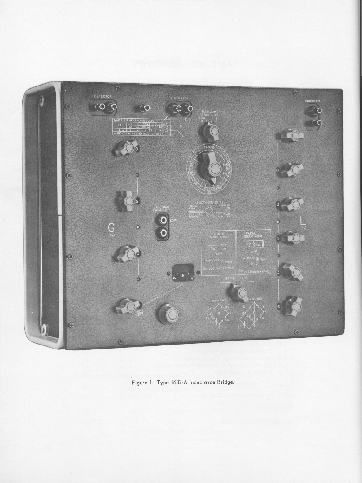
Figure
1.
Type
1632-A
Inductance
Bridge
.
TYPE
1632-A
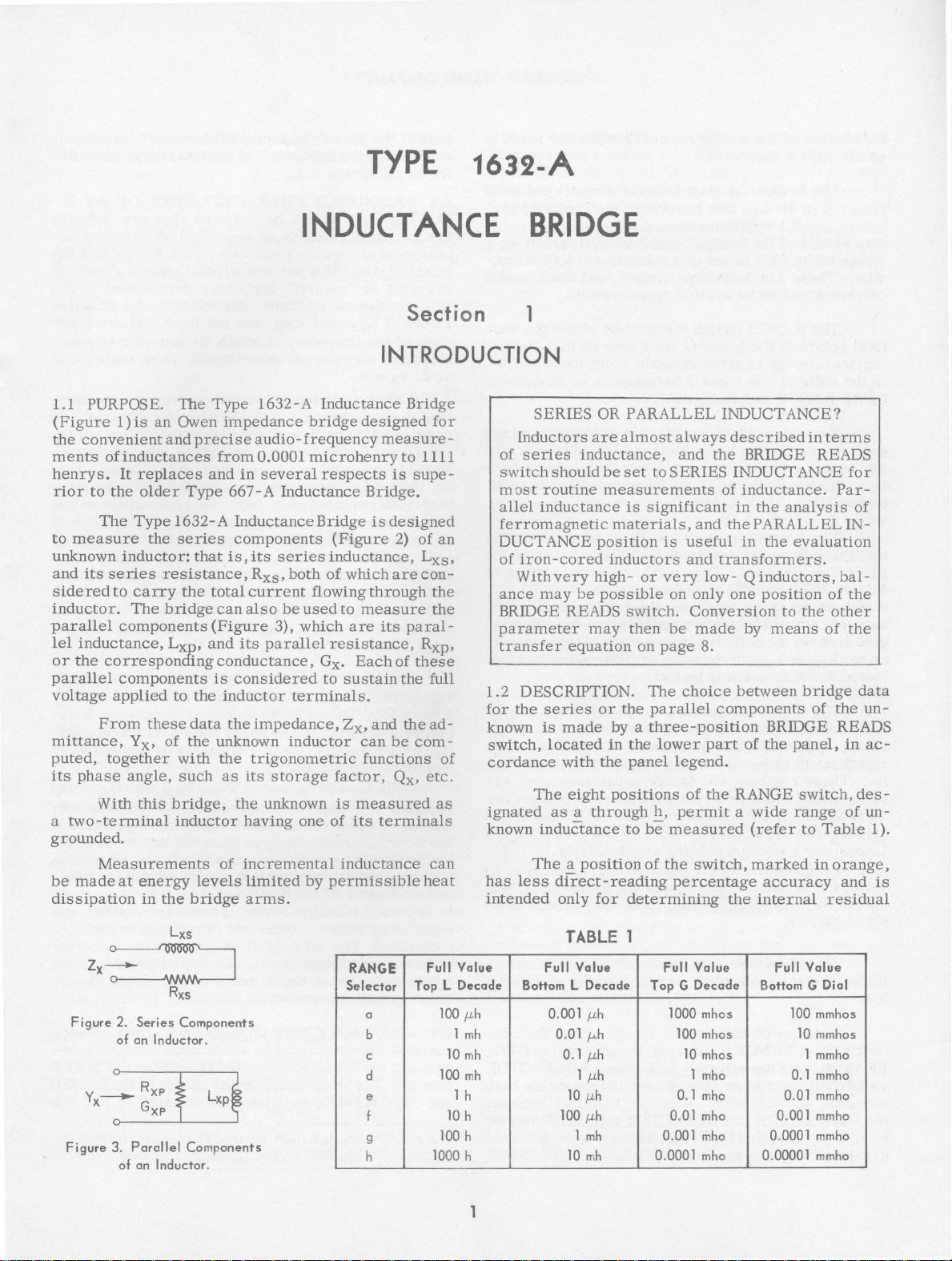
1.1 PURPOSE.
(Figure
the
ments
henrys.
rior
to
unknown
and
side
inductor.
parallel
lel
or
parallel
voltage
mittance,
puted,
its
a
two-terminal
1)
is
convenient
of
inductances
It
replaces
to
the
The
Type
measure
inductor:
its
series
red
to
carry
The
components
inductance,
the
corresponding
components
applied
From
Yx, of
together
phase
With
angle,
this
older
the
these
grounded.
Measurements
be
made
at
energy
dissipation
in
The
Type
1632-A
an
Owen
impedance
and
precise
Type
audio-frequency
from
0.0001
and
in
several
667-A Inductance
1632-A Inductance
series
resistance,
the
bridge
that
total
is,
can
components
its
Rxs,
current
also
(Figure
Lxp•
and
its
parallel
conductance,
is
considered
to
the
inductor
data
the
impedance,
the
unknown
with
the
trigonometric
such
as
its
bridge,
inductor
the
of
levels
bridge
the
unknown
having
incremental
limited
arms.
INDUCTANCE
Section
INTRODUCTION
bridge
microhenry
series
both
flowing
be
used
3),
which
terminals.
inductor
storage
one
by
Inductance
respects
Bridge
(Figure
inductance,
of
which
to
are
resistance,
Gx.
Each
to
sustain
Zx,
factor,
is
measured
of
its
inductance
permissible
Bridge
designed
measure
to
is
supe-
Bridge.
is
designed
2)
are
through
measure
its
paral
of
the
and
the
can
be
com-
functions
Qx,
terminals
fo r
1111
of
an
Lxs.
con-
the
the
Rxp•
these
full
ad-
of
etc.
as
can
heat
-
-
BRIDGE
1
SERIES
Inductors
of
series
switch
m o
st
routine
allel
inductance
ferromagnetic material
DUCT
ANCE
of
iron-cored
Withvery
ance
may
BRIDGE READS
parameter
transfer
1.2
DESCRIPTION.
for
the
series
known
switch,
is
located
cordance
The
ignated
known
inductance
The a position
has
less
intended
OR
PARALLEL
are
almost
inductance,
should
be
set
measurements
is
position
inductors
high-
be
possible
switch.
may
equation
or
the
made
by a three-position
in
with
the
eight
positions
as a through
to
direct-reading
only
for
determining
to
SERIES
significant
is
or
very
on
then
be
on
page
The
parallel
the
lower
panel
legend.
h,
be
measured
of
the
percentage
INDUCTANCE?
always
and
described
the
BRIDGE READS
INDUCTANCE
of
inductance. Par-
in
the
s ,
and
the PARALLEL
useful
and
only
in
the
transformers.
low-
Qinductors,bal-
one
position
Conversion
made
by
means
8.
choice
between
components
BRIDGE READS
part
of
the
of
the
RANGE
permit a wide
(refer
switch,
marked
accuracy
the
internal
in
terms
analysis
evaluation
of
to
the
other
of
bridge
of
the
panel,
switch,
range
to
Table
in
orange,
residual
for
of
IN-
the
the
in
des-
of
and
data
un-
ac-
un-
1 ).
is
Figure 2. Series Components
of
on
Inductor.
Figure 3. Parallel Components
of
on
Inductor.
RANGE
Selector
a
b
c
d
e
f
g
h
TABLE
Full Value Full Value Full Value Full Value
Bottom
Top L Decade
100
,uh
1
mh
10
mh
100
mh
1 h
10
h
100
h
1000
h
L Decade
0.
001
0.
01
0. 1
1
10
100
1
10
,uh
,u.h
,uh
,uh
,uh
,uh
mh
mh
1
Top G Decade Bottom G Dial
1000
mhos
100
mhos
10
mhos
1
mho
0. 1
0.
0.
0.
001
0001
01
mho
mho
mho
mho
0.
0.
00001
0.
0.
0001
100
10
1
0.1
01
001
mmhos
mmhos
mmho
mmho
mmho
mmho
mmho
mmho
GENERAL
RADIO
COMPANY
inductance
small-valued
The
either
henrys
able
maximum
mho.
extremes
Lxs
and
values
of
These
cannot
The
imal
points
merical
in
by
the
six
trol.
tively
the
units
the
RANGE
Two
bridge.
decade
Each
0,
display
independent
1,
The X position
numerically
preceding
8X5.0X3
When
balance
give
either
by
the
directly
Lxs
the
RANGE
corresponds
bridge
controls
TI1e G
panel,
uously
right),
its.
calibrated
ductance,
legend.
consists
adjustable
which
These
to
G,
The
11-position
......
units,
unit
air
in
the
9,
and
is
in
the
capacitor.
The
use
upper
2.4.
of
the
bridge
or
inductors.
bridge
0.1
RANGE
can
thus
or
Lxp
that
are
millimicrohenry.
of
the
bridge
1111
mhos
are
individual
be
switch
in
the L and G read-outs
is
given
of
the
Land G parameters
switch
conductance,
to a minimum
applied
mechanism
directly,
legend.
controls
On
the
right-hand
switches
switch
.....
that
has
9,
constitute
11
positions
and
X.
corresponds
equivalent
decade.
to
Thus
to a numerical
is
balanced,
(which
the
self-inductance
or
Lxp•
selector
balance
of
is
readable,
controls
indicate
in
units
upper
switch~s,
and
X.
numerically
preceding
of
the
center
are
in
the
units
legend.
control,
four
decade
dial
(displaced
by
are
decade
directly
indicated
four
decades
reading
The X position
equivalent
decade.
two-position
panel
corrections
indicate
within
directly
the
The
directly
of
ranges,
and
concurrently.
shifts
so
from
are
used
side
of
the L balance
reading
to
10
one
additional
an L balance
value
the
readings
actually
value
of
inductance
on
the
decade
of
left-hand
switches
out
interpolation,
capacitors,
the
balance
by
the
RANGE
of
the G control
consecutively,O,
corresponds
to
The
fifth
SENSITIVITY
is
discussed
for
leads
values
limits
of 1111
read-
G,
are
from
0.01
micro-
the L and
the
dec-
that
the
top
to
bottom,
as
designated
for
balancing
the
panel
con-
consecu-
units,
unit
and
in
setting
of
905.103.
ofthese
resistors)
the
unknown,
indicated
side
and a contin-
of
line
to
to
two
dig-
and
bridge
con-
selector
1,
to
one
additional
decade
is
switch
in
paragraph
nu-
are
is
the
of
of
the
are
are
2,.
10
an
to
permit
the
extendedbytheadditionof
fer
to
paragraph
of
1.3
FREQUENCY
DUCTOR.
has a certain
a
pacitance
G
inductor
resonant
two
values
tions
gized
or
reactive
of
of
and
de
values.
itself
or
Lxs
the
When
bridge,
the
augmented
the
unknown
L
itance
ly,
may
"free"
are
care
Bridge
which
sible
at
ured
between
the
bridge-measured
differ
unknown,
measured
has
been
to
loads
value
least
minimize, a correction
data
When
higher
a few
than
kilocycles
quires a negative
ity,
as a capacitor,
an
inductance
The
inductor
quency.
the
as
the
is
increased
lectric
iron
creased
At
de
resistance
frequency
losses
-cored
by
are
material.1
creases
a
maximum
some
with
specific
upper
range
2. 7.
It
should
effective
across
its
is a resonant
"natural"
parameters.
and
frequency
may
depart
an
inductor
inductor's
by
the
direct
terminals
the
appreciably
especially
at
higher
taken
reduce
the
this
free
(about
(refer
an
its
to
inductor
natural
for
phase
bridge.
loss
parameters,
likewise
sufficiently
by
is
by
eddy
in
the
inductor
eddy
currents
The
manner
frequency
phase
frequency.
of
the G balance
anexternal
CHARACTERISTICS
be
realized
or
so-called
terminals.
circuit
frequency
that
This
and
determined
Accordingly,
Lxp
are
not
fixed,
at
which
the
inductor
substantially
is
connected
own
distributed
two
connecting
capacitance
of
the
that
bridge,
leads.
parameters
from
the
true
when
large
frequencies.
in
the
Type
1632-A
bridge-terminal
inductor,
l.OfJfJf),
paragraph
is
frequency
large
angle
so
that
functions
low
only
raised,
currents
distributed
these
causes
angle
to
and
thus
to
4.1).
energized
values
of
and
it
cannot
Rxs.
of
frequencies
an
insignificant
the
effective
in
the
losses
and
hysteresis
in
which
any
and
storage
the
the
(which
inductance)
functions,
Rxp.
the.
capacitance.
ac
control
capacitor.
OF
any
to
be
Re-
AN IN-
inductor
"distributed" ca-
means
that
the
has a specific
by
its
the
effective
but
are
func-
is
ener-
from
their
basic
to
any
impedance
capacitance
exists
plus
the
across
capac-
Consequent-
of
the
unknown
values
of
the
inductance
Considerable
Inductance
capacitance,
smallest
to
eliminate,
pos-
or
bridge-meas-
at a frequency
may
be
only
it
ac-
in
real-
be
measured
and
exciting
Rxs
amount,
ac
resistance
winding
are
further
in
resistance
inductor
factor,
Gx
of
any
fre-
exceeds
but
and
die-
In
in-
the
core
in-
to
have
Qx,
on
an
at
is
s
Jack-top
necting
the
ERATOR,
as
labeled,
terminal
the
GENERATOR
used
for
ground.
binding
UNKNOWN
and
the
the
red
of
each
connecting
Two
jacks
posts
inductor,
external
insulating
pair.
and
DETECTOR
the
bridge
marked
are
the
null-balance
cone
A
single
chassis
EXTERNAL
provided
external
DETECTOR
indicating
terminal
terminals
to
an
CAPACITOR
for
con-
ac G EN-
the
high
between
may
be
external
1.4
ACCURACY
controls
cent
percent.
and
l•A
RADIO EXPERIMENTER , Vol 24, No. 2,
are
and
the G balance
The
SENSITIVITY
New
Decade
OF
MEASUREMENT.
calibrated
to a tolerance
controls
bridge
components
switches
Inductor" Horatio
2
are
are
calibrated
chosen
adjusted
W.
Lamson
July
The L balance
of
±0.05
by
, GENERAL
1949 .
the
so
per-
to
±1.0
RANGE
that
the
TYPE
1632-A
INDUCTANCE
BRIDGE
product
sistance
±0.05
of
the
in
the B arm
percent.
capacitance
Consequently,
unknown
be expected
± 1
Q
determinations
2.1
having
low
generator
put
measurements
former
a
Variac® autotransformer,
tween
bridgeuses
Frequency
Type
Unit
inductor,
for
inductance
percent
AC
harmonic
voltage.
for
resistance
GENERATOR. Any
the
desired
waveform
should
include a means
If
ac
at
and
an
adjustable
the
line
and
Adequate
generator
canbeprovided
Audio
1210-C
Amplifier,
Unit
or
an
will
frequency
50
the
Generator,
by
tor.
Type
1632-
Pl
Impedance
When
low-valued
RANGE
put
or
adequate
selector
impedance
10-ohm
resistance
voltage
from a generator
than
this,
an
be
connected
bridge
purpose
keep
the
The
input.
and
the
magnetic
bridge
OUTPUT
and
inductors
set
of
the
without
having
impedance-matching
between
The
Type
is
designed
field
from
terminals
in
has a tolerance
for
the
direct
accuracy
values,
values.
then
be± 1 percent
adjustable
range
distortion
power
or
60
mains
cycles, an
autotransformer,
should
bridge.
range
by
RC
Oscillator
the
Type
are
at
positions
bridge
of
the
may
ratio
distortion
an
output
the
generator
1632-
to
plug
of
the
the
inductor
of
the
the A ann
of
measurement
of ±0.1
percent
and
The
tolerance
plus
OPERATING
ac generator
and
satisfactorily
may
be
of
adjusting
are
to
isolation
b'e
inserted
and
power
the
Type
1304-B
by
the
combination
and
Type
1311-
A Audio
Matching
Pl
into
transformer
transformer
Transformer.
measured
a,
b,
c,
or
be
-as
low
arm
RB·
to
drive
impedance
transformer
output
is
supplied
the
generator
being
and
the
less
than
of
may
accuracy
the
Section
used.
the
out-
be
used
trans-
such
for
most
Beat-
1206-B
Oscilla-
with
d,
the
~s
the
To
obtain
the
bridge
higher
must
and
for
away
from
measured.
marked
re-
an
of
of
tol-
The
for
as
be-
of
the
in-
l-
the
this
to
erance
These
about 5 kc.
rect
impedances
paris
tution
with
which
specifications
At
higher
measurements
in
the
Much
smaller
on
can
be
obtained
technique
(refer
the
operating
are
frequencies
is
reduced
bridge
tolerances
by
to
frequency
valid
up
the
because
(refer
to
for
use
of
paragraph
to a frequency
accuracy
of
Section
inductance
the
direct
2.13).
2
PROCEDUR
20:
1,
when
provide
1
minals
25:1,
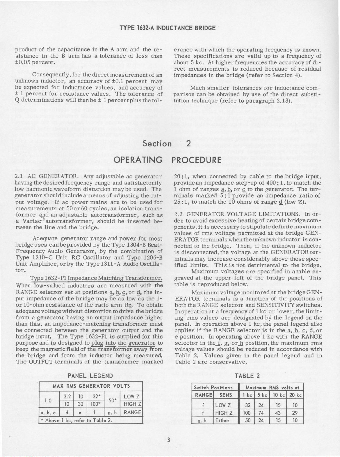
2.2 GENERATOR VOLTAGE LIMITATIONS.
der
ponents,
values
ERATOR
nected
is
minals
ified
graved
table
ERA
both
In
ing
panel.
applies
~position.
selector
voltage
Table
Table 2 are
an
ohm
of
marked
to
match
to
avoid
it
of
to
disconnected,
may
limits.
Maximum
at
is
reproduced
Maxim
TOR
the
RANGE
operation
nns
In
if
values
2.
,E
connected
impedance
ranges~
is
nns
terminals
the
the
terminals
values
operation
the
in
Values
•
.Q,
5 : 1
the
10
excessive
necessary
voltage
when
bridge.
the
increase
This
is
voltages
upper
urn
voltage
selector
at a frequency
are
RANGE ·
In
operating
the_f,
.&
should
given
conservative.
by
cable
step-up
or.£
provide
ohms
heating
to
of
to
the
an
of
of
stipulate
permitted
the
unknown
Then,
voltage
if
at
considerably
not
detrimental
are
specified' in a table
left
of
the
below.
monitored
is a function
and
SENSITIVITY
of 1 kc
designated
above 1 kc,
selector
above 1 kc
or_h
position,
be
reduced
in
the
to
the
400:
1,
generator.
impedance
range
Q.
(low
certain
definite
at
the
inductor
the
unknown
the
GENERATOR
above
to
bridge
at
the
of
the
or
lower,
by
the
the
panel
is
in
the_a,
with
the
maximum
in
accordance
panel
legend
bridge
to
bridge
bridge
these
the
panel.
bridge G EN-
positions
legend
legend
the
is
known.
of
di-
residual
4).
com-
substi-
input,
match
The
the
ter-
ratio
Z).
In
or-
com-
maximum
GEN-
is
con-
inductor
ter-
spec-
bridge.
en-
This
switches.
the
limiton
the
also
_Q,
..£,
Q,
RANGE
nns
with
and
of
of
of
or
in
MAX
1.0
a,
b,
c d
*Above
PANEL
RMS
3.2
10
1 kc, refer
LEGEND
GENERATOR VOLTS
10
32*
32
100*
e f
to
Table
LOW
50*
HIGH Z
g,
h RANGE
2.
TABLE
Switch
Positions
Z
RANGE
g, h
f
f
SENS
LOW
Z
HIGH Z
Either
Maximum
1 kc
32
100
50
2
5 kc
24
74
24
RMS
10
43
l5
15
volts
kc
20
at
kc
10
29
10
3
2.3
NULL
ative
with
tector
erating
on
the
unknown
having
the
bridge
frequency.
precision
Lxs
generator
response,
for
monitoring
come
overloaded
ance.
render
This
the
uncertain.
The
the
Type
1231-B Amplifier
Type
1231-PS
indicator
phones,
Type
quiring
single
down
bridge
an
1231-B
only
Type
A
specially
turns
network
transformer
minal
of
the
flflf)
thus
introduced
is
compensated
transformer
pacitance
2.4
USE
OF
should
bridge
tector
can
is
the
Rs,
this
value
normally
calibrations
has a very
be
shown
maximum
operating
that
switch
of
Rs
capacitor,
bridge,
remains
rors.
is
unchanged,
With
negligible
ance
controls
With
iron
change
change
in
of
unknown.
In
the
frequencies,
ploy
the
larger
position.
the
midrange
in
the
~~'
DETECTOR.
iron-cored
abundant
with
,i.e.,
the
number
or
Lxp
voltage.
the
null
detector
gain
when
might
cause
preliminary
requirements
Adjustable
with
additional
It
inductors,
selectivity
The
sensitivity
which
value,
so
Even
that
the
subject
if
bridge
considerable
bridge
for a detector
and
Filter,
gain,
is
desirable,
it
is
of
digits
it
is
should
the
detector
balance
Null
such
to
employ a null
at
required
desired
to
logarithmic
include a control
is
badly
Detector
followed
as a pair
oscilloscope, a millivoltmeter,
Null
Detector.
the
direct-reading
1231-B
with
shielded
ratio
of
3:1,
and
the
permits
null
direct
detector.
across
for
in
introduces
across
the B arm.
THE
SENSITIVITY SWITCH.
be
kept
are
high
that
the
balance
when
the
impedance
frequency,
constitutes
is
is
increased
C A,
reduced
shifted
which
tenfold,
the B arm
from
constitutes
except
air-cored
changes
when
-cored
inductors
in
the
the
SENSITIVITY
inductors
the L and G balance
the
actual
interest
it
This
values
andJ.
voltage
of
may
occasionally
RB
value
SENSITIVITY
of
positions.
For
measurements
accuracy
filter
is
usually
transformer,
is
interposed
DETECTOR
grounding
The' capacitance
the A arm
the
calibration
practically
in
its
LOW-Z
most
accurate.
(infinite)
input
sensitivity
of
is
equal
of
LOW
tenfold
so
for
and
that
small
there
setting
of
there
settings
at
the
balance
sensitivity
be
obtained
switch
the
RANGE
In
positions ~ b,
zero
to
the
-Z
the A arm
the
the L and G balswitch
may
terminals
desirable
with
selector,
GENERAL
and
the
chosen
to
required
the
permissible
will
out
confusion
difficult
can
be
with
by a null
of
or
of ±0.1%, a
adequate.
with a step-
between
terminals.
of
the
low
(about
of
the
of CA.
residual
This
position
If
the
impedance,
of
the
the
unknown,
the
resistance,
bridge.
to
HIGH -z
the
value
product
calibration
will
is
be a large
owing
at
the
functions
imper-
deop-
depends
balance
in
the
in
its
not
be-:-
of
bal-
and
and
met
by
the
head-
another
re-
the
This
ter-
100
bridge
The
ca-
switch
where
null
de-
bridge
at
When
the
of
the
of
the
Rs
CA
er-
be
only
shifted.
to
of
the
higher
to
em-
HIGH-Z
only
in
namely
c,
g,
RADIO
and
SENSITIVITY
2.5
is
magnetic
far
bridge
acting
also
it
field
treme
ment
cies,
appreciable
may
tector
line
right
one
terminal
ground,
terminal
small-valued
be
re~tion.
for
leads
so
generator
so
gain
observable
it
former
connect
appropriate
high
generator
bridge
an
one
DETECTOR
edge
for
a
2.6
RANGE
amplefromc
of
is
known
that
ranges
COMPANY
_h_no
change
SETUP
nonastatic
enough
be
does
that
since
be
frequencies,
terminal
used
those
that
that,
detector
lead
earth
point
of
operation.
USE
CA
increased
the
OF
field
away
cabinet,
on
the
far
enough
not
pick
might
precautions
of
nonastatic
most
magnetic
demonstrated
across
Connect
of
the
has
join
that
to
avoid,
For
in
excess
should
The
generator
there
should
with
the
pickup
that
feeds
Using
the
the
ac
bridge
of
each
voltage
(refer
If
it
is
ground,
only,
the
bridge
OF
selector
is
increased
the
value
bridge
of
the L and G balance
is
made
in
switch
is
EQUIPMENT.
in
character,
when
energized,
from
all
to
prevent
unknown
and
away
up
directly
be
broadcast
should
inductors
laboratories
field
by
the
unknown.)
unless
the
unknown
bridge,
of
an
this
is
to
the
unknown
inherently
terminal
in
contact
inductors,
or
at
larger-valued
of
100
be
used
to
and
is
no
direct
be
placed
generator
connected
by
the
the
detector
shielded
generator
terminals.
goes
to
at
zero
to
paragraph
desired
such
to
connection
namely,
and
GENERATOR
panel.
either
shifted.
metal
induced
giving
from
any
be
at
connection
Measurements
demanded,
the
UNKNOWN
to
with
twisted
least
mh,
minimize
detector
pickup
far
disconnected
t.o
the
(internal)
concentric
and
the
until
2.8).
connect
at
the
The
Rs
If
the
so
that
it
should
objects,
currents from
false
the
generator
significant
from
the
taken
at
power-line
are
permeated
these
frequencies.
of a
inductor,
is
grounded,
larger
the
UNKNOWN
the
bridge
insulated
minimize, a lead
inductors,
nearly
capacitive
should
between
enough
bridge,
terminals.
the
null
taking
red
terminal.
ready
the
should
terminal
terminals
equipment
THERANGESELECTOR.
is
advanced
to
d),
either
tenfold
by a factor
of
this
may
be
by
the
value
so
that
of 10.
product
balanced
one
the
For
must
within
controls
or
C A
unknown
it
broadcasts
be
such as
data.
generator.
in
the
tuned
are
best
placed
terminals.
capacitance
panel.
leads
and
parallel
be
positioned
them.
from
the
and
there
shielded
leads
detector
care
to
balance
whole
be
between
on
is
now
Wheneverthe
position
of
Rsorthe
product
any
be
chosen
the
and
when
inductor
locate
re-
It
must
so
that
magnetic
Ex-
measure-
frequen-
with
(This
null
de-
at
power-
avoided.
at
or
if
one
bridge
For
may
cor-
certainly
bare
loading.
The
bridge
the
full-
will
be
trans-
supplied,
to
that
the
Keep
the
tJhe
system
made
the
upper
ready
(for
ex-
value
RsCA
given
un-
available
at
the
a
d
the
an
the
If
to
no
the
to
at
the
so
the
4
TYPE
1632•A
INDUCTANCE
BRIDGE
same
balance
The
permit
balance
are
indicated
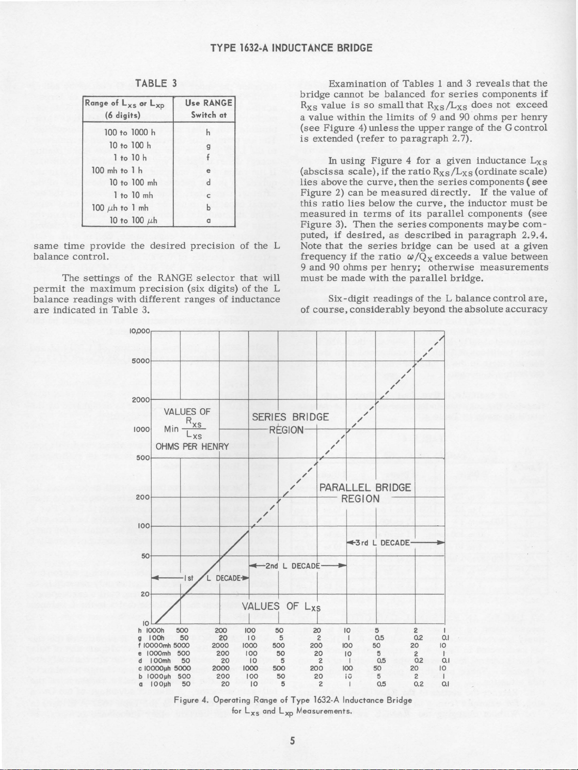
Range
time
control.
settings
the
readings
af
Lxs
(6
digits)
100
to
10
to
to
1
100
mh
to
10
to
1
to
100 p.h
to 1 mh
10
to
provide
of
maximum
with
in
Table
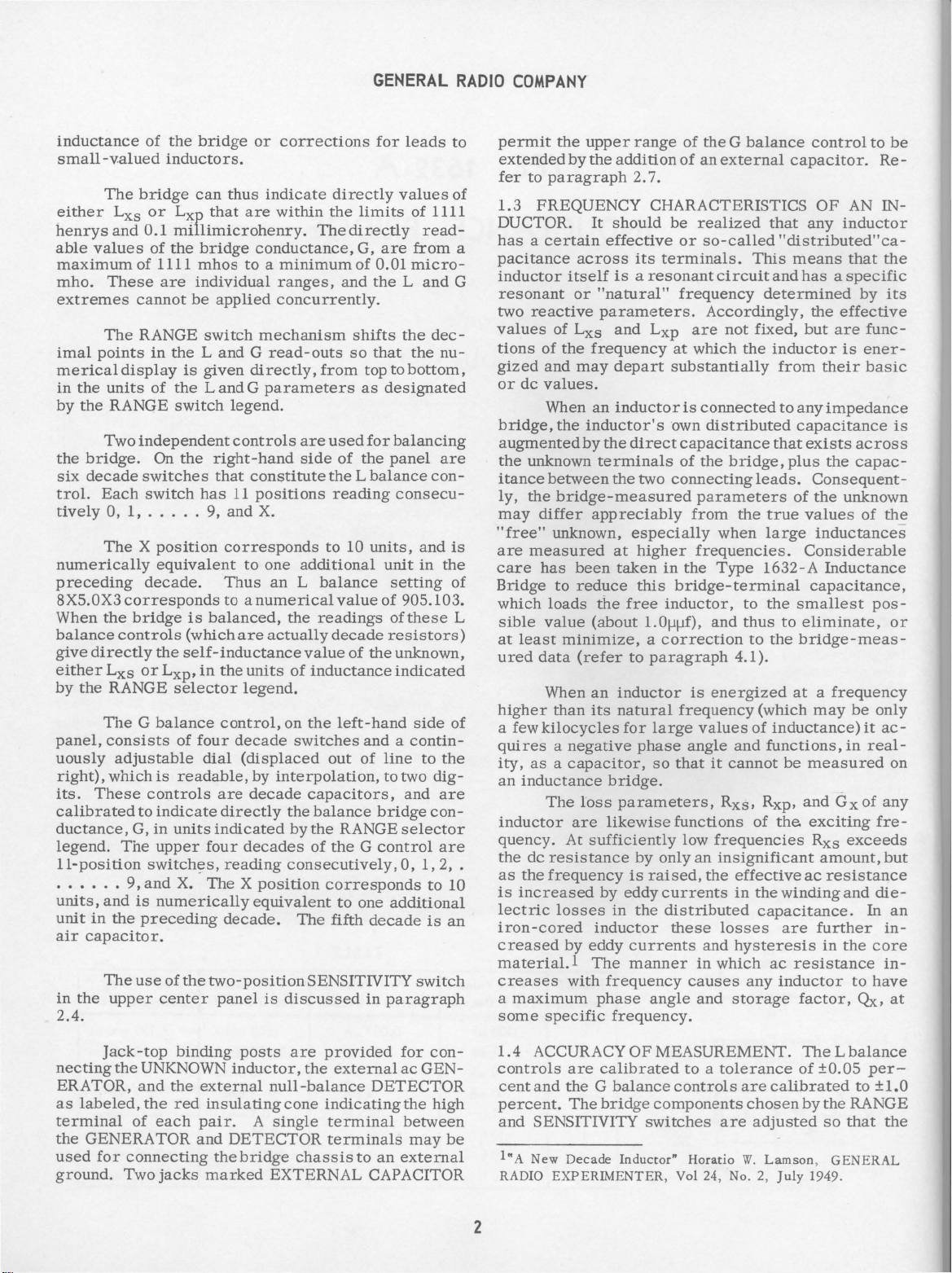
TABLE 3
or Lxp
1000 h h
100 h
10
h
1 h
100
mh
10
mh
100 p.h
the
desired
the
precision
different
Use
RANGE
ranges
Switch
precision
selector
(six
3.
IOPOO
5000
2000
1000
500
200
100
VALUES
Min
OHMS
R
_2_L
Lxs
PER
OF
RANGE
at
g
f
e
d
c
b
a
digits)
of
HENRY
of
the
L
that
will
of
the
L
inductance
SERIES BRIDGE
REGION
/
/
/
bridge
Rxs
a
(see
is
(abscissa
lies
Figure
this
measured
Figure
puted,
Note
frequency
9
must
of
/
/
//
Examination
cannot
value
value
within
Figure
extended
In
is
4)
(refer
using
be
so
small
the
unless
Figure 4 for a given
scale),
above
the
curve,
2)
can
be
ratio
lies
below
in
terms
3).
Then
the
if
desired,
that
the
series
if
the
ratio
and
90
ohms
per
be
made
with
Six-digit
course,
readings
considerably
_,'
,
/
/
/
,
"
"
"
""
PARALLEL BRIDGE
REGION
of
Tables 1 and 3 reveals
balanced
limits
the
to
paragraph
if
the
then
measured
the
of
series
as
bridge
henry;
the
for
that
Rxs/Lxs
of 9
and
upper
ratio
Rxs/Lxs
the
series
directly.
curve,
its
parallel
components
described
can
w/Qx
exceeds a value
otherwise
parallel
of
the L balance
beyond
series
range
2. 7).
the
in
be
bridge.
the
/1
/
"
/
/
/
"
components
does
not
90
ohms
of
the G control
inductance
(ordinate
components
If
the
inductor
components
maybe
paragraph
used
measurements
control
absolute
that
the
if
exceed
per
henry
Lxs
scale)
(see
value
of
must
be
(see
com-
2. 9.4.
at a given
between
are,
accuracy
50
20
/
10
h
IOOOh
9 lOCh
f
IOOOOmh
e
IOOOmh
d
IOOmh
c
100001Jh
b
10001Jh
a
IOO!Jh
/
.-2nd
,YDECADE+
VALUES
500
50
5000
500
50
5000
500
50
Figure
200 100
2000
200
2000
200
4.
Operating
I I
50
10 5 2 I 0.5
20
20
20
1000
1000
for
500
100
100
Lxs
50
10 5
500
50
10 5 2 0.5
Range
and Lxp
L
DECAD
I
I
OF
Lxl
of
Type
Measurements.
5
20
200
20
2
200
20
1632-A
-+3
rd L
10
100
10
100
iO
Inductance
5 2
50
I 0.5
50
DECADE
5
5
Bridge
20
20
Q.2
2
02
2
0.2
10
10
0.1
I
0.1
I
0.1
I
 Loading...