

Page 1

NAVAIR 17–20AG–295
TECHNICAL MANUAL
AG–295
INSTRUMENT CALIBRATION PROCEDURE
RANDOM–NOISE GENERATOR
GENRAD
1381
THIS PUBLICATION SUPERSEDES NAVAIR 17–20AG–295
DATED 1 JANUARY 1979 CHANGED 1 APRIL 1986
DISTRIBUTION STA TEMENT C. DISTRIBUTION AUTHORIZED TO U.S. GOVERNMENT AGENCIES AND THEIR
CONTRACTORS TO PROTECT PUBLICA TIONS REQUIRED FOR OFFICIAL USE OR FOR ADMINISTRA TIVE OR
OPERA TIONAL PURPOSES ONL Y . OTHER REQUESTS FOR THIS DOCUMENT SHALL BE REFERRED TO NA VY
MEASUREMENT SCIENCE DIRECTORATE, NAVAL WARFARE ASSESSMENT STATION, P.O. BOX 5000
CORONA, CA 92878–5000.
DESTRUCTION NOTICE– FOR UNCLASSIFIED, LIMITED DOCUMENTS, DESTROY BY ANY
METHOD THAT WILL PREVENT DISCLOSURE OF CONTENTS OR “RECONSTRUCTION OF THE
DOCUMENT.”
PUBLISHED BY DIRECTION OF COMMANDER NAVAL AIR SYSTEMS COMMAND
15 APRIL 1986
AG–295
Page 2

NAVAIR 17–20AG–295
LIST OF EFFECTIVE PAGES
The purpose of this list is to identify the pages in this document affected by any technical content changes made since the
previous release of the document.
NOTE: On a revised page, with the exception of the Title, the A, and the i pages, the technical changes are indicated by a
vertical line in the outer margin of the page.
Page
No.
Title 0
A 0
i 0
1 to 3 0
4 (blank) 0
5 0
Revision*
Page
No.
Revision*
Page
No.
Revision*
* Zero in this column indicates an original page.
“R” in this column indicates a revised page.
A
Page 3

NAVAIR 17–20AG–295
TABLE OF CONTENTS
Section Page
1 Introduction and Description 1. . . . . . . . . . . . . . . . . . . . . . . . . . . . . . . . . . . . . . . . . . . . . . . . . . . . . .
2 Equipment Requirements 1. . . . . . . . . . . . . . . . . . . . . . . . . . . . . . . . . . . . . . . . . . . . . . . . . . . . . . . . .
3 Preliminary Operations 2. . . . . . . . . . . . . . . . . . . . . . . . . . . . . . . . . . . . . . . . . . . . . . . . . . . . . . . . . .
4 Calibration Process 2. . . . . . . . . . . . . . . . . . . . . . . . . . . . . . . . . . . . . . . . . . . . . . . . . . . . . . . . . . . . . .
4.1 Output Voltage Tests 2. . . . . . . . . . . . . . . . . . . . . . . . . . . . . . . . . . . . . . . . . . . . . . . . . . . . . . . . . . .
4.2 Random Noise Spectrum T ests 3. . . . . . . . . . . . . . . . . . . . . . . . . . . . . . . . . . . . . . . . . . . . . . . . . . .
Navy Calibration Checklist 5. . . . . . . . . . . . . . . . . . . . . . . . . . . . . . . . . . . . . . . . . . . . . . . . . . . . . . .
TABLES
T able Page
1 Calibration Description 1. . . . . . . . . . . . . . . . . . . . . . . . . . . . . . . . . . . . . . . . . . . . . . . . . . . . . . . . . .
2 Equipment Requirements 2. . . . . . . . . . . . . . . . . . . . . . . . . . . . . . . . . . . . . . . . . . . . . . . . . . . . . . . . .
i
Page 4

NAVAIR 17–20AG–295
SECTION 1
INTRODUCTION AND DESCRIPTION
1.1 This procedure describes the calibration of the GenRad 1381 Random–Noise Generator, herein referred to as the TI
(Test Instrument).
1.2 All comments concerning this procedure should be directed to Navy Measurement Science Directorate, Naval Warfare
Assessment Station, P.O. Box 5000, Corona, CA 92878–5000.
1.3 This procedure includes tests of essential performance parameters only. Any malfunction noticed during calibration,
whether specifically tested for or not, should be corrected.
T able 1. Calibration Description
TI
Characteristics
Performance
Specifications
T est
Method
Output voltage
Random noise spectrum
1.4 This procedure does not perform tests for Clipping or Amplitude density distribution.
Minimum use specifications are the principal parameters required for performance of the calibration, and are
included to assist in the selection of alternate equipment, which may be used at the discretion of the using
laboratory . Satisfactory performance of alternate items shall be verified prior to use. All applicable
equipment must bear evidence of current calibration.
Spectrum: 2, 5, and 50 kHz
bandwidths
T olerance: >3 V rms max. open
circuit voltage, any bandwidth
None
SECTION 2
EQUIPMENT REQUIREMENTS
NOTE
Measured with an av meter (true
rms voltmeter).
Observed with an oscilloscope.
The instruments utilized in this procedure were selected from those known to be available at Navy
calibration facilities, and the listing by make or model number carries no implication of preference,
recommendation, or approval for use by other agencies. It is recognized that equivalent equipment produced
by other manufacturers may be capable of equally satisfactory performance in this procedure.
1
Page 5
NAVAIR 17–20AG–295
T able 2. Equipment Requirements
Minimum Use
Item
2.1 AV meter
2.2 Oscilloscope
3.1 Ensure that all power switches are set to off, and set all auxiliary equipment controls as necessary to avoid damage to
the equipment and so that dangerous voltages will not be present on output terminals when the power switches are turned on.
3.2 Connect the auxiliary equipment, and the TI, to the appropriate power source.
True rms readout
Range: 0 to 10 V
Frequency: 10 Hz to 50 kHz
Uncertainty: +3%
Input Z: 1 M min.
Bandwidth: DC to 1 MHz
Sweep time: 0.1 s/div to 2.0 s/div
Vertical input Z: 1 M min.
Specifications
Hewlett–Packard
T ektronix 7704OPT02, 03
SECTION 3
PRELIMINAR Y OPERATIONS
Calibration
Equipment
3403COPT003, 3400A or
931BOPT001
with a 7B53A and 7A26 or
7A13 plug in units
7904OPT03, 7A26/7B92A
3.3 Turn all power switches on, and allow a sufficient warm up time for the equipment. (The TI requires 10 minutes warm
up time.)
SECTION 4
CALIBRATION PROCESS
NOTE
Unless otherwise specified, verify the results of each test and take corrective action whenever the test
requirement is not met, before proceeding.
4.1 OUTPUT VOLTAGE TESTS
4.1.1 Set the TI controls as follows:
BANDWIDTH switch to 2 kHz
CLIPPING switch to () infinity
OUTPUT LEVEL control to Max. CW
4.1.2 Set the av meter controls for measuring 3 V rms, and then connect the TI OUTPUT connector to the av meter input
connector.
4.1.3 Verify that the av meter indication is equal to or greater than 3 V rms.
2
Page 6

NAVAIR 17–20AG–295
4.1.4 Set the TI BANDWIDTH switch to 5 kHz, and verify that the av meter indication is equal to or greater than 3 V rms.
4.1.5 Set the TI BANDWIDTH switch to 50 kHz, and verify that the av meter indication is equal to or greater than 3 V rms.
4.1.6 Adjust the TI OUTPUT LEVEL control fully ccw, and verify that the av meter indication is less than 30 mV rms.
4.1.7 Disconnect the av meter from the TI OUTPUT connector.
4.2 RANDOM NOISE SPECTRUM TESTS
4.2.1 Connect the TI OUTPUT connector to the oscilloscope vertical input connector, and set the oscilloscope controls for
an internally triggered sweep time of 0.1 s/div.
4.2.2 Adjust the TI OUTPUT LEVEL control fully cw, the BANDWIDTH switch to 2 kHz, and verify that the signal
displayed is random noise as the oscilloscope sweep time is increased from 0.1 s/div. to 50.0 s/div.
4.2.3 Set the TI BANDWIDTH switch to 5 kHz, and verify that the signal displayed is random noise as the oscilloscope
sweep time is varied between 0.1 s/div. and 20.0 s/div.
4.2.4 Set the TI BANDWIDTH switch to 50 kHz, and verify that the signal displayed is random noise as the oscilloscope
sweep time is varied between 0.1 s/div. and 2.0 s/div.
4.2.5 Unless other measurements are to be performed, set all power switches to off, and disconnect the TI.
(4 blank) 3
Page 7
CALIBRATION CHECKLIST
TEST INST (S)
GenRad 1381 Random–Noise Generator
NAVAIR 17–20AG–295
PROC. NO.
PROCEDURE
STEP
NO.
(1)
NA 17–20AG–295
FUNCTION TESTED
(2)
MFG. MODEL
NOMINAL
(3)
MEASURED VALUES
FIRST RUN
(4)
SECOND RUN
(5)
OUT
OF
TOL
(6)
SER. NO.
CALIBRATION TOLERANCES
(7)
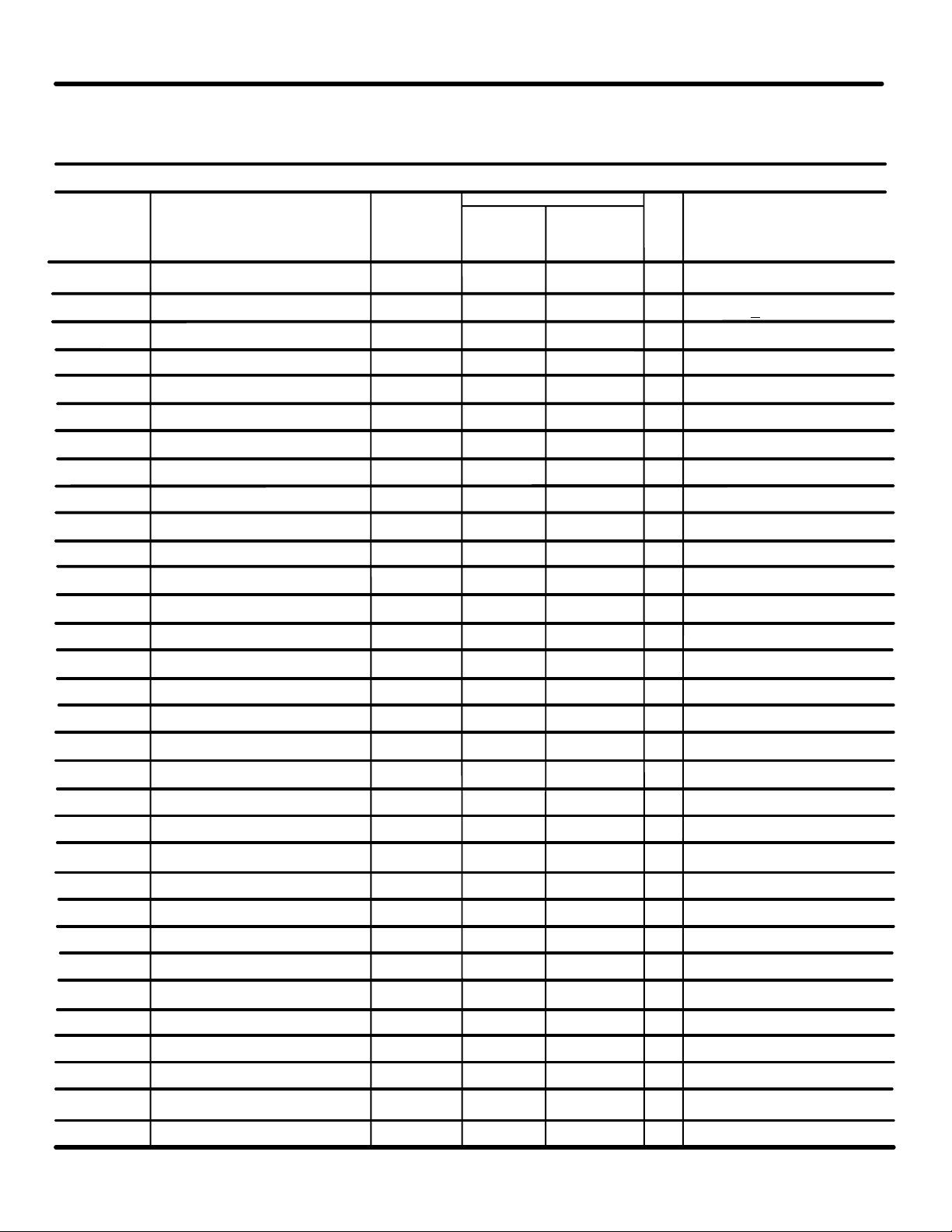
4.1 Output Voltage Tests
4.1.3 Bandwidth – 2 kHz –– ck ( ) >3 V rms
4.1.4 Bandwidth – 5 kHz –– ck ( ) ”
4.1.5 Bandwidth – 50 kHz –– ck ( ) ”
4.1.6 OUTPUT LEVEL fully ccw –– ck ( ) < 30 mV rms
4.2 Random Noise Spectrum Tests
4.2.2 2 kHz – Random noise –– ck ( ) random noise display
4.2.3 5 ” – ” –– ck ( ) ”
4.2.4 50 ” – ” –– ck ( ) ”
Page 1 of 1
5
 Loading...