

General Pump TSF Series 66 Servicing Instructions
GENERAL PUMPA member of the Interpump Group
8
SERVICING INSTRUCTIONS
SERVICING PUMP PROCEDURES
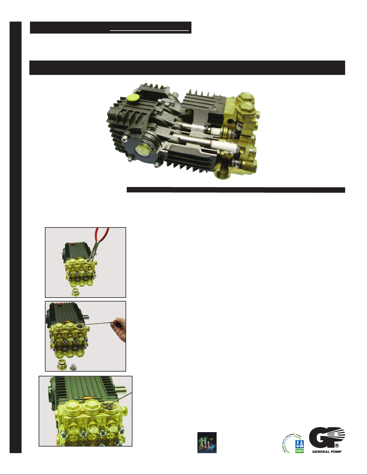
TSF Series “66”
Triplex Plunger Pump
Valve Replacement: All inlet and discharge valves can be serviced without disrupting the inlet or discharge
plumbing. The inlet and discharge valves are identical in all 66 TSF series models.
To service any valve:
1) Remove valve cap (using 30 mm socket) and examine o-ring.
Replace o-ring if there is any evidence of cuts, abrasions, distortion or
wear.
2) Remove valve assembly (retainer, spring, valve, valve seat) from
valve cavity.
3) Remove valve seat o-ring from valve cavity.
4) Inspect manifold for wear or damage.
TRIPLEX TRIPLEX
5) Install new o-ring in valve cavity.
6) Insert valve assembly into valve cavity.
7) Replace valve cap and torque to specification.
NOTE: Only one valve kit is necessary to repair all the valves
in the pump. The kit includes new o-rings, valve seat, poppet, spring and
retainer. All are pre-assembled.
Ref 300872 Rev. B
General Pump
is a member of
the Interpump Group
09-15
TSF Series “66”
Servicing Instructions
GENERAL PUMPA member of the Interpump Group
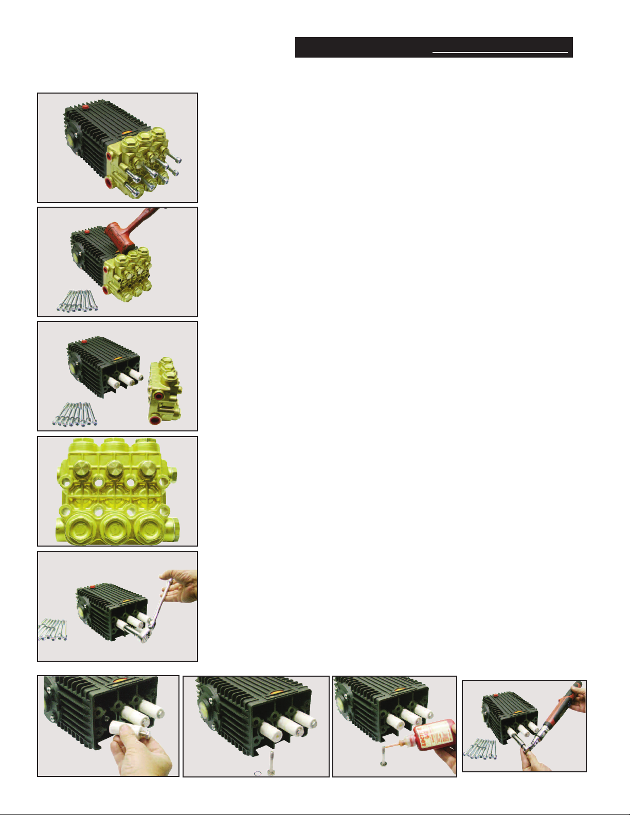
Removing/Installing Manifold:
1) Remove fasteners retaining manifold (using 8 mm hex socket).
2) Separate manifold from crankcase.
Note: it may be necessary to rotate the crankshaft, or tap the manifold
lightly with rawhide mallet to loosen the manifold from crankcase.
Caution: When sliding head from crankcase use caution not to damage
plungers.
3) The seal assemblies may come off with the manifold. At this point
examine the ceramic plungers. Plunger’s surface should be smooth
and free from scoring, pitting, or cracks; if not, replace.
4) Coat each plunger with grease.
5) Align outside pistons in the forward position.
6) Reinstall manifold and torque to specifications per sequence
described below.
TORQUE SEQUENCE FOR TIGHTENING MANIFOLD:
14 67
5328
• Install all manifold bolts finger tight.
• Torque to 10 foot pounds in sequence as shown.
• Next torque to specification; again, in sequence.
Replacing ceramic plungers:
1) Remove the plunger retaining bolts with O-ring (using 14 mm socket).
2) Remove the ceramic plunger from piston rod.
3) Inspect plunger bolt O-ring and replace as necessary.
4) Slide new plunger over the piston rod.
5) Apply a drop of removable anaerobic thread sealant to
threads of plunger bolt.
7) Install plunger bolt and torque to specifications.
Ref 300872 Rev. B
09-15
 Loading...