

SK
8
Owner’s Manual
• Installation
• Use
• Maintenance
General Pump is a
member of the
Interpump Group
Ref 300792 Rev.C
06-12

GENERAL PUMP
INDEX
1. INTRODUCTION . . . . . . . . . . . . . . . . . . . . . . . . . . . . . . . . . . . . . . . . . . . . . . . . . . . . . . . . . . . . . . .Page 3
2. DESCRIPTION OF SYMBOLS . . . . . . . . . . . . . . . . . . . . . . . . . . . . . . . . . . . . . . . . . . . . . . . . . . . .Page 3
3. SAFETY . . . . . . . . . . . . . . . . . . . . . . . . . . . . . . . . . . . . . . . . . . . . . . . . . . . . . . . . . . . . . . . . . . . . . .Page 4
3.1 General safety instructions . . . . . . . . . . . . . . . . . . . . . . . . . . . . . . . . . . . . . . . . . . . . . . . . . . . . .Page 4
3.2 High pressure unit safety requirements . . . . . . . . . . . . . . . . . . . . . . . . . . . . . . . . . . . . . . . . . . .Page 4
3.3 Safety during operation . . . . . . . . . . . . . . . . . . . . . . . . . . . . . . . . . . . . . . . . . . . . . . . . . . . . . . .Page 4
3.4 General procedures for using nozzles . . . . . . . . . . . . . . . . . . . . . . . . . . . . . . . . . . . . . . . . . . . .Page 4
3.5 Safety during unit maintenance . . . . . . . . . . . . . . . . . . . . . . . . . . . . . . . . . . . . . . . . . . . . . . . . .Page 5
4. PUMP IDENTIFICATION . . . . . . . . . . . . . . . . . . . . . . . . . . . . . . . . . . . . . . . . . . . . . . . . . . . . . . . . .Page 5
5. TECHNICAL CHARACTERISTICS . . . . . . . . . . . . . . . . . . . . . . . . . . . . . . . . . . . . . . . . . . . . . . . . .Page 6
6. DIMENSIONS AND WEIGHT . . . . . . . . . . . . . . . . . . . . . . . . . . . . . . . . . . . . . . . . . . . . . . . . . . . . . .Page 7
7. OPERATING INSTRUCTIONS . . . . . . . . . . . . . . . . . . . . . . . . . . . . . . . . . . . . . . . . . . . . . . . . . . . . .Page 7
7.1 Water temperature . . . . . . . . . . . . . . . . . . . . . . . . . . . . . . . . . . . . . . . . . . . . . . . . . . . . . . . . . . .Page 7
7.2 Maximum flow and pressure rates . . . . . . . . . . . . . . . . . . . . . . . . . . . . . . . . . . . . . . . . . . . . . . .Page 7
7.3 Minimum RPM . . . . . . . . . . . . . . . . . . . . . . . . . . . . . . . . . . . . . . . . . . . . . . . . . . . . . . . . . . . . . .Page 7
7.4 Recommended lubricant types and manufacturers . . . . . . . . . . . . . . . . . . . . . . . . . . . . . . . . . .Page 8-9
A member of the Interpump Group
SK SERIES
8. PORTS AND CONNECTIONS . . . . . . . . . . . . . . . . . . . . . . . . . . . . . . . . . . . . . . . . . . . . . . . . . . . . .Page 10
8.1 Conical seal pads/ferrules . . . . . . . . . . . . . . . . . . . . . . . . . . . . . . . . . . . . . . . . . . . . . . . . . . . . .Page 10
9. PUMP INSTALLATION . . . . . . . . . . . . . . . . . . . . . . . . . . . . . . . . . . . . . . . . . . . . . . . . . . . . . . . . . .Page 11
9.1 Installation . . . . . . . . . . . . . . . . . . . . . . . . . . . . . . . . . . . . . . . . . . . . . . . . . . . . . . . . . . . . . . . . .Page 11
9.2 Direction of rotation . . . . . . . . . . . . . . . . . . . . . . . . . . . . . . . . . . . . . . . . . . . . . . . . . . . . . . . . . .Page 12
9.3 Hydraulic connections . . . . . . . . . . . . . . . . . . . . . . . . . . . . . . . . . . . . . . . . . . . . . . . . . . . . . . . .Page 12
9.4 Pump power supply . . . . . . . . . . . . . . . . . . . . . . . . . . . . . . . . . . . . . . . . . . . . . . . . . . . . . . . . . .Page 12
9.5 Inlet line . . . . . . . . . . . . . . . . . . . . . . . . . . . . . . . . . . . . . . . . . . . . . . . . . . . . . . . . . . . . . . . . . . .Page 12
9.6 Filtration . . . . . . . . . . . . . . . . . . . . . . . . . . . . . . . . . . . . . . . . . . . . . . . . . . . . . . . . . . . . . . . . . . .Page 13
9.7 Outlet line . . . . . . . . . . . . . . . . . . . . . . . . . . . . . . . . . . . . . . . . . . . . . . . . . . . . . . . . . . . . . . . . . .Page 13
9.8 Internal diameter of hose . . . . . . . . . . . . . . . . . . . . . . . . . . . . . . . . . . . . . . . . . . . . . . . . . . . . . .Page 14
10. START UP AND OPERATION . . . . . . . . . . . . . . . . . . . . . . . . . . . . . . . . . . . . . . . . . . . . . . . . . . . . .Page 15
10.1 Preliminary inspections . . . . . . . . . . . . . . . . . . . . . . . . . . . . . . . . . . . . . . . . . . . . . . . . . . . . . .Page 15
10.2 Starting up . . . . . . . . . . . . . . . . . . . . . . . . . . . . . . . . . . . . . . . . . . . . . . . . . . . . . . . . . . . . . . . .Page 15
10.3 Cooling circuit seal packing . . . . . . . . . . . . . . . . . . . . . . . . . . . . . . . . . . . . . . . . . . . . . . . . . . .Page 16
11. PREVENTATIVE MAINTENANCE . . . . . . . . . . . . . . . . . . . . . . . . . . . . . . . . . . . . . . . . . . . . . . . . .Page 16
12. PUMP STORAGE . . . . . . . . . . . . . . . . . . . . . . . . . . . . . . . . . . . . . . . . . . . . . . . . . . . . . . . . . . . . . .Page 17
12.1 Inactivity for lengthy periods . . . . . . . . . . . . . . . . . . . . . . . . . . . . . . . . . . . . . . . . . . . . . . . . . . .Page 17
12.2 Filling the pump with anti-corrosion emulsion or anti-freeze . . . . . . . . . . . . . . . . . . . . . . . . . .Page 17
12.2 Hoses . . . . . . . . . . . . . . . . . . . . . . . . . . . . . . . . . . . . . . . . . . . . . . . . . . . . . . . . . . . . . . . . . . . .Page 17
13. PRECAUTIONS AGAINST FREEZING . . . . . . . . . . . . . . . . . . . . . . . . . . . . . . . . . . . . . . . . . . . . . .Page 17
14. WARRANTY TERMS . . . . . . . . . . . . . . . . . . . . . . . . . . . . . . . . . . . . . . . . . . . . . . . . . . . . . . . . . . . .Page 17
15 TROUBLESHOOTING . . . . . . . . . . . . . . . . . . . . . . . . . . . . . . . . . . . . . . . . . . . . . . . . . . . . . . . . . . .Page 18
16. EXPLODED VIEWS AND PARTS . . . . . . . . . . . . . . . . . . . . . . . . . . . . . . . . . . . . . . . . . . . . . . . . . .Page 19
17. REPAIR KITS . . . . . . . . . . . . . . . . . . . . . . . . . . . . . . . . . . . . . . . . . . . . . . . . . . . . . . . . . . . . . . . . . .Page 21
17. MAINTENANCE LOG . . . . . . . . . . . . . . . . . . . . . . . . . . . . . . . . . . . . . . . . . . . . . . . . . . . . . . . . . . .Page 22
Ref 300792 Rev.C
06-12
Page 2
GENERAL PUMP
A member of the Interpump Group
SK SERIES
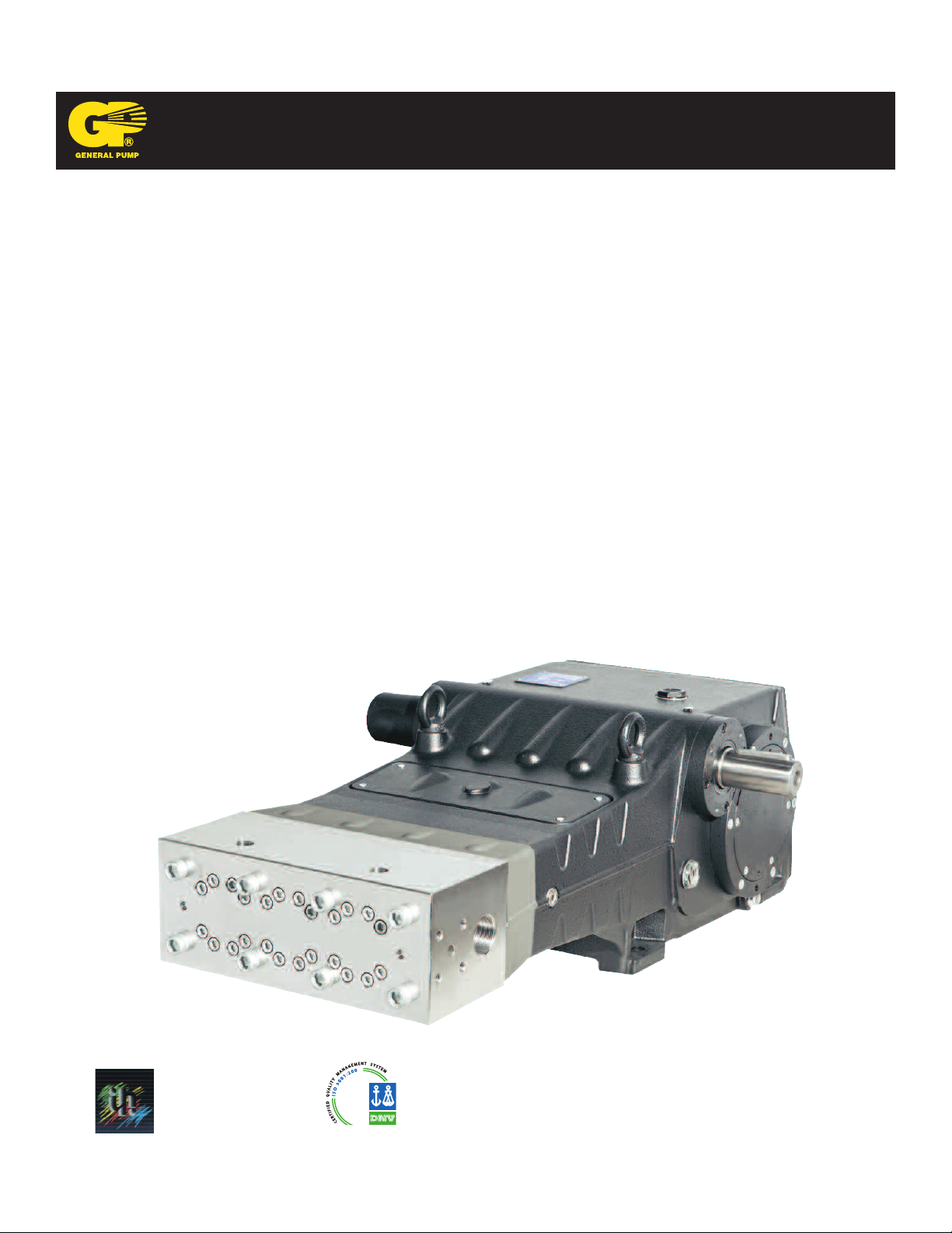
1. INTRODUCTION
This manual describes the use and maintenance instructions of the SK pump, and should be carefully read and
understood before using the pump.
Correct use and adequate maintenance will guarantee the pumps trouble-free operation for a long time. General Pump
declines any responsibility for damage caused by misuse or the non-observance of the instructions indicated in this
manual.
Upon receiving the pump, check that it is complete and in perfect condition. Should anything be found out of order, please
contact us before installing and starting the pump.
2. SYMBOL DESCRIPTIONS
Warning
Potential Danger
Read carefully and understand
the manual before operating
the pump
Danger
High Voltage
Danger
Wear protective mask
Danger
Wear goggles
Danger
Wear protective gloves
Danger
Wear protective boots
Ref 300792 Rev.C
06-12
Page 3
GENERAL PUMP
A member of the Interpump Group
SK SERIES
3. SAFETY
3.1 General Safety Indications
Improper use of pumps and high pressure systems, and/or failure to observe the installation and maintenance
instructions may cause serious injury to people and/or damage to property. Anyone assembling or using high pressure
systems must possess the necessary competence to do so, should be aware of the characteristics of the components
assembled/used, and must take all precautions necessary to ensure maximum safety in any operating condition. In the
interest of safety, both for the Installer and the Operator, no reasonably applicable precaution should be omitted.
3.2 High pressure unit safety requirements
1. The pressure line must always be equipped with a safety valve.
2. High pressure system components, in particular for those units working outside, must be adequately
protected against rain, frost and heat.
3. The electrical control system must be adequately protected from water spray, and must comply with the
specific regulations in force.
4. High pressure hoses must be properly sized for maximum operating pressure of the system and always and only
used within the operating pressure range specified by the hose manufacturer. The same rules should be observed
for all other auxiliary systems affected by high pressure.
5. The ends of high pressure hoses must be sheathed and secured to a solid structure to prevent dangerous
whiplash in case of bursting or broken connections.
6. Appropriate safety guards must be provided for the pump transmission systems (couplings, pulleys and belts,
auxiliary drives).
3.3 Safety During Operation
The working area of a high pressure system must be clearly marked. Access must be prohibited to un-authorized
personnel and, wherever possible, the area should restricted or fenced. The personnel authorized to access this area
should first be trained, and informed about the risks that may arise from failures or malfunctions of the high pressure unit.
Before starting the unit, the operator must verify that:
1. The high pressure system is properly fed by a minimum pressure of 75-100 PSI (5-7 Bar), metered in the head
flange.
2. The pump intake filters are perfectly clean; we recommend the use of a device that indicates the filters clogging level.
3. Electrical parts are adequately protected and in perfect condition.
4. The high pressure hoses do not show evident signs of abrasion, and that fittings are in perfect shape.
Any fault or reasonable doubt that may arise before or during operation should be promptly reported and verified by
competent personnel. In these cases, pressure should immediately be released and the high pressure system
stopped.
3.4 General Procedures For Using Nozzles
1. The Operator must always place his own and other worker’s safety before any other interest; his and should always
be governed by good sense and responsibility.
2. The Operator must always wear a helmet with a protective visor, waterproof clothing, and appropriate boots capable
of guaranteeing grip on wet pavement.
Ref 300792 Rev.C
06-12
Page 4
GENERAL PUMP
Note: appropriate clothing will effectively protect against water spray, but it may not offer adequate protection against the
direct impact of water jets or sprays from a close distance. Some circumstances may require further protection.
3. It is generally best to organize personnel into teams of at least two people capable of giving mutual and immediate
assistance in case of necessity and of taking turns during long and demanding operation.
4. Access to the work area that is within the water jets’ range must be absolutely prohibited to and free from objects
that, inadvertently under a pressure jet, can be damaged and or create dangerous situations.
5. The water jet must only and always be directed in the direction of the work area, including during testing or
preliminary tests or checks..
6. The Operator must always pay attention to the trajectory of the debris removed by the water jet. If necessary,
suitable guards must be provided by the Operator to protect anything that may be accentally exposed.
7. The Operator should not be distracted for any reason during operation. Workers needing to access the operating
area must wait for the Operator to stop work, and then immediately make their presence known.
8. For safety reasons, it is important that each member of the team is fully aware of the intentions and actions of
other team members in order to avoid dangerous misunderstandings.
9. The high pressure system must not be started up and run under pressure without all team members in position
and without the Operator having already directed his/her lance toward the work area.
3.5 Safety During System Maintenance
1. The pressure system maintenance must be carried out in the time intervals set by the manufacturer who is
responsible for the whole group according to law.
2. Maintenance should always be carried out by trained and authorized personnel.
3. Assembly and disassembly of the pump and its various components must be performed exclusively by authorized
personnel, using appropriate equipment in order to avoid damage to components and connections.
4. Always use original spare parts to ensure total reliability and safety.
A member of the Interpump Group
SK SERIES
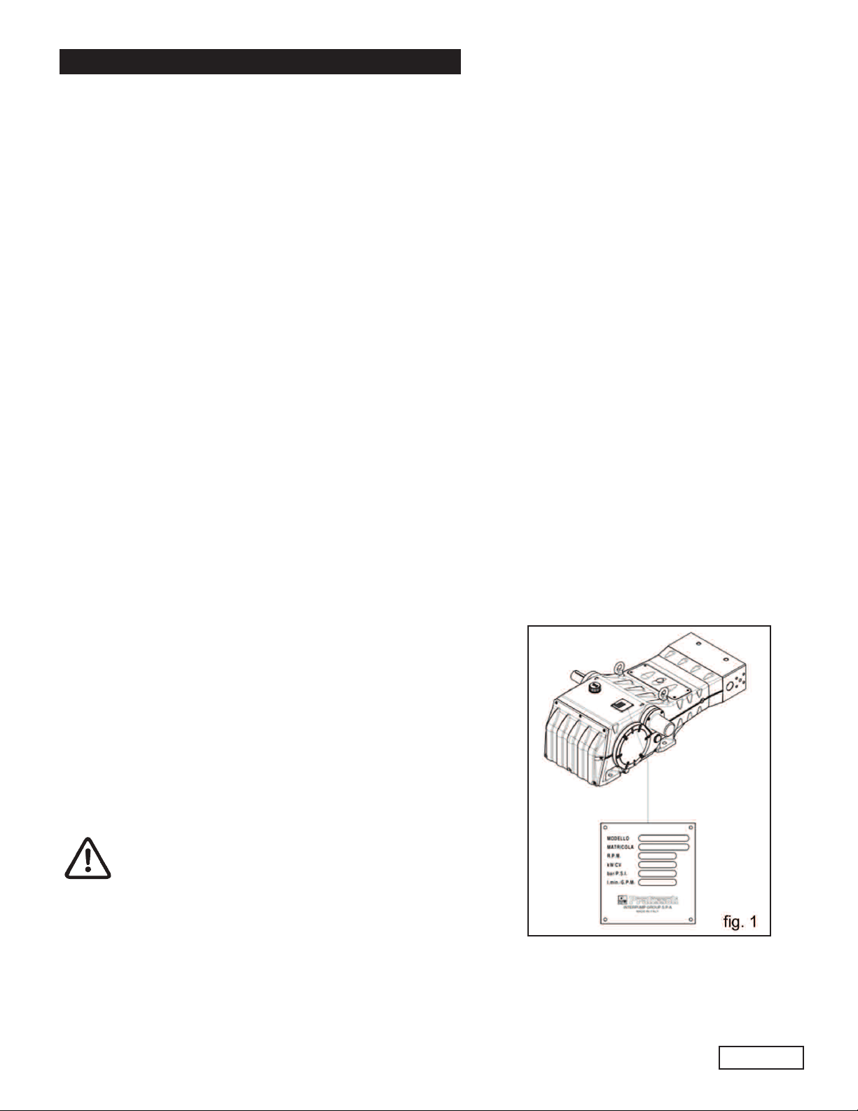
4. PUMP IDENTIFICATION
Each pump has a specific label which contains:
Pump model and version
Serial Number
Maximum RPM
Power - Hp-kW
Pressure - PSI
Flow Rate - GPM
Pump model, version and serial number must always
be specified when ordering spare parts.
Ref 300792 Rev.C
06-12
Page 5

GENERAL PUMP
5. TECHNICAL FEATURES
A member of the Interpump Group
SK SERIES
MODEL RPM
SK2015 1500 11.4 43 21750 1500 168 123
SK2017 1750 11.6 44 21750 1500 171 126
SK2215 1500 13.7 52 18850 1300 176 1291
SK2217 1750 14.0 53 18850 1300 179 132
SK2415 1500 16.4 64 14500 1000 177 130
SK2417 1750 16.6 63 14500 1000 180 132
SK2615 1500 19.3 73 13050 900 171 126
SK2617 1750 19.5 74 13050 900 173 127
SK2815 1500 22.2 84 11600 800 175 128
FLOW RATE PRESSURE POWER
GPM l/min PSI Bar Hp kW
SK2817 1750 22.7 86 11600 800 179 132
SK3015 1500 25.3 97 10150 700 175 128
SK3017 1750 25.97 98 10150 700 178 131
Ref 300792 Rev.C
06-12
Page 6
GENERAL PUMP
A member of the Interpump Group
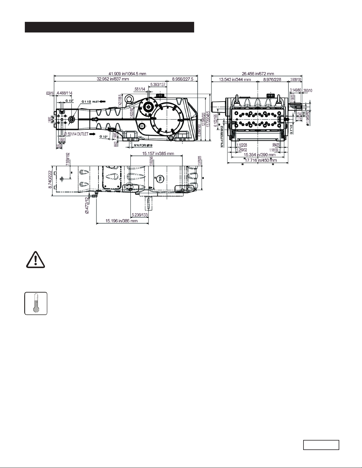
6. DIMENSIONS AND WEIGHT
For dimensions and weight, please refer to fig. 2.
SK SERIES
Weight: 840 Lbs./381 Kg.
fig. 2
7. INFORMATION ABOUT PUMP USE
The SK pump was designed to operate with filtered water (see paragraph 9.7) and at
maximum temperature of 104oF (40oC).
Other fluids may be used only upon the approval of The Customer Service Department .
7.1 WaterTemperature
The max water temperature is 104oF (40oC).However, it is possible to use the pump at temperatures of up
to 140oF (60oC) for short periods of time. In this case we advise consulting the Customer Service
Department.
7.2 Max Flow Rate and Pressure Values
The performance values indicated in the catalog refer to the maximum performance of the pump. Regardless of the power
used, pressure and maximum RPM values indicated on the plate may not be exceeded unless expressly authorized by the
Customer Service Department.
7.3 Lowest RPM
Any RPM value different from what is indicated in the performance table (see chapter 5) must be explicitly authorized by
the Customer Service Department.
Ref 300792 Rev.C
06-12
Page 7

GENERAL PUMP
7.4
Recommended Lubricant Oil Types & Manufacturers
The pump is delivered with lubricant oil compliant with room temperatures ranging between 32oand 89.6oF (0oand
30oC ). Some recommended lubricant types are indicated in the table below; these lubricants are treated with additives
in order to increase corrosion protection and resistance to fatigue. As an alternative, Automotive SAE 85W-90 gearing
lubricants may also be used.
A member of the Interpump Group
BRAND TYPE
GENERAL PUMP SERIES 220
ARAL Aral Degol BG220
BP ENERGOL HLP 220
CASTROL
ELF
ESSO NUTO 220
FINA Cirkan 220
FUCHS RENOLIN 220
MOBIL DTE OIL BB
SHELL TELLUS C 220
TEXACO RANDO HD 220
TOTAL CORTIS 220
Hyspin VG 220, Magna
POLYTELIS 220
SK SERIES
220
Check the oil level with the oil level lights located on the sides (1, fig. 3). If necessary, top off via the
oil plug (3, fig. 3).
To correctly check the oil level the pump must be at ambient temperature. To change the oil the pump
must be at operating temperature, and is done by removing the plug (2, fig. 3).
Checking and changing the oil must be done as shown in Chapter 11. The quantity necessary is 473.4
oz. (14 liters).
Ref 300792 Rev.C
06-12
Page 8

GENERAL PUMP
In any case, oil must be changed at least once a year since it may deteriorate by oxidation.
For room temperatures that differ from that mentioned earlier, follow the indications contained in the diagram
below, keeping in mind that the oil must have a minimum viscosity of 180 cSt.
A member of the Interpump Group
SK SERIES
VISCOSITY/ROOM TEMPERATURE DIAGRAM
Exhausted oil must be collected in an appropriate container and disposed of in appropriate
locations. Do not under any circumstances discard it into the environment.
Ref 300792 Rev.C
Page 9
06-12

GENERAL PUMP
A member of the Interpump Group
SK SERIES
8. PORTS AND CONNECTIONS
SK Series pumps are equipped with (see fig. 4):
1. 2 inlet ports “IN”, 1-1/2” BSP-F.
The line can be connected to either of the two inlet ports; the ones not being used must be hermetically sealed.
2. 2 outlet ports “OUT”, Ø 3/4” HP Special.
3. 2 service ports, 1/2”. These can be used for the pressure gauge
3. 1 drain port “DRAIN” with G1/2” hole in the lower cover to moniter any water leakage due to wear of the pressure
packings. In case of leaks, please consult the repair manual.
This hole must always be kept open.
8.1 Conical seal pads/ferrules
SK pumps are provided with 4 steel conical pads, for use in the corresponding outlet ports of the pump (see fig. 5) or in
the optional connection flanges, to ensure the connection seal. While the seat of the pump’s outlet port is already
machined to accept the conical pad, if it is necessary to make the connection for the outlet connection or the closing
plug, these must be specifically machined as shown in fig. 5a.
At every disassembly, the conical pads must be replaced.
Ref 300792 Rev.C
06-12
Page 10
GENERAL PUMP
A member of the Interpump Group
SK SERIES
9. PUMP INSTALLATION
9.1 Installation
The pump must be installed in a horizontal position using the drilled Ø19 support feet. The base must be perfectly flat and
rigid enough as not to allow bending or misalignment on the pump coupling and axis/transmission due to torque transmitted during operation.
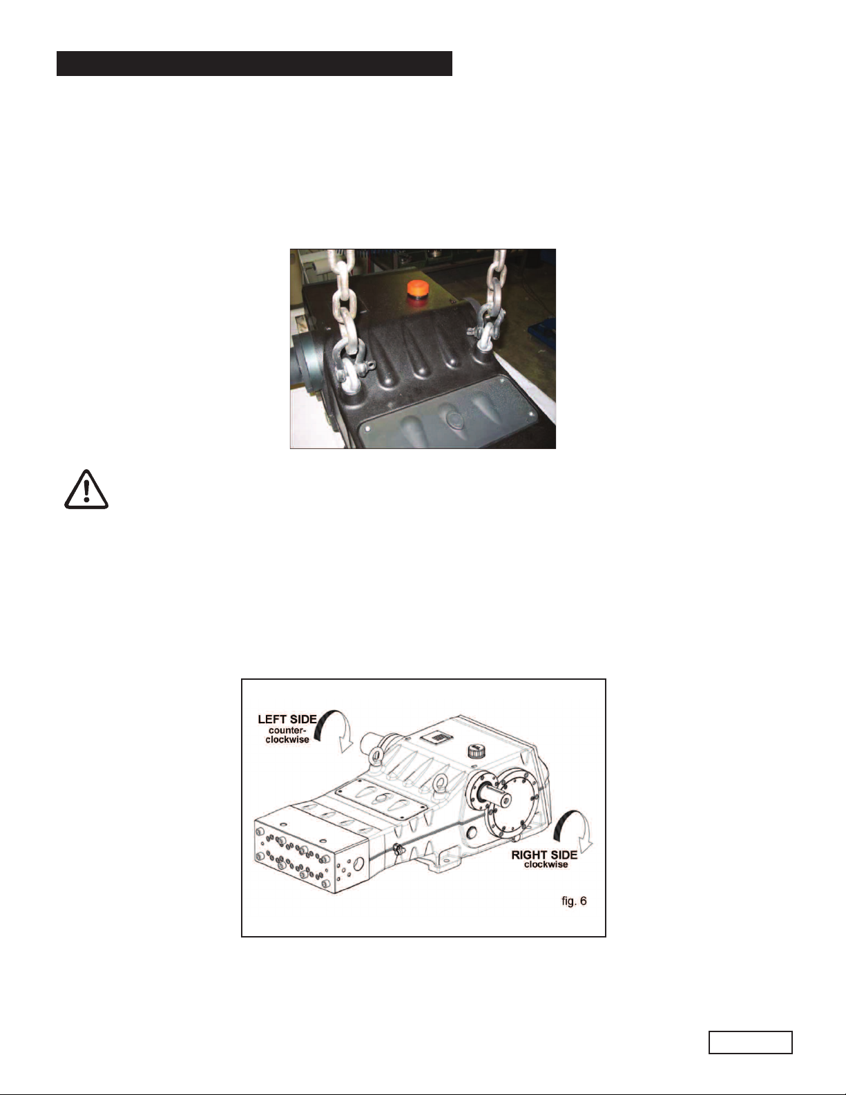
Two lifting eyebolts are mounted on the pump for easy installation, as per the figure below.
The pump’s shaft (PTO) must not be rigidly connected to the motor unit.
The following transmission types are suggested:
• Flexible joint
• Cardan Joint (please respect the maximum working angles indicated by the manufacturer)
9.2 Direction of rotation
The PTO rotation is indicated by an arrow located on the reduction gear cover. From a position facing the pump head,
the rotation direction will be as in fig. 6.
Ref 300792 Rev.C
06-12
Page 11

GENERAL PUMP
The power take-off can be taken from either side of the pump. Generally the pump is supplied with the PTO shank for
the right-hand side (see fig. 6). To get the power take-off from the left hand side, the shaft end cover must be taken off
and remounted on the right hand side of the pump (see 2.1.1 in the Repair Manual). Vice-versa, the lug must be
removed from the right hand side and inserted in the shank of the left hand side.
9.3 Hydraulic Connections
To isolate the plant from the vibrations produced by the pump, we recommend building the first section of hose
adjacent to the pump (for both intake and outlet) with flixible hose. The solidity of the intake section must be enough
to prevent deformation caused by the depression produced by the pump.
9.4 Pump Supply
SK pumps require a positive water head (NPSHr) of between 75-100 PSI (5-7 Bar) at the pump head entrance. The
booster supply pump must have a flow rate at least double that of the rated flow rate of the plunger pump, and a mini-
mum pressure of 75 PSI (5 bar). These supply conditions must be respected for any and all working regimes. The
booster pump must be run independent of the plunger pump.
The booster pump must always be started before the plunger pump. We recommend
installing a pressure switch on the supply line downstream of the filters, to protect the pump.
A member of the Interpump Group
SK SERIES
9.5 Suction Line
For the pump’s correct operation, the suction line must have the following characteristics:
1. Minimum internal diameter as indicated in the diagram in paragraph 9.8 and in any case equal or greater
than the pump head’s value. Along the duct, avoid localized diameter reductions that may cause pressure
drops with subsequent cavitation. Absolutely avoid 90oelbows, connections with other hoses, bottlenecks,
counter-slopes, upside down “U” shaped curves, “T” connections.
2. With a layout that is set in such a way to prevent cavitation.
3. It should be perfectly airtight, and built in a way that guarantees perfect sealing over time.
4. Avoid pump emptying when stopping (even partial emptying).
5. Do not use hydraulic fittings, 3 or 4 way fittings, adapters, etc., since they may hinder the pump’s
performance.
6. Do not install Venturi tubes or injectors for detergent intake.
7. Avoid the use of standing valves, check valves, or any other type of one-way valves.
8. Do not connect the by-pass line from the valve directly to the pump suction line.
9. Provide appropriate baffle plates inside the tank in order to avoid water flows coming from both the by-pass
and feeding lines may create turbulance near the tank’s outlet port.
10. Make sure that the suction line is perfectly clean inside before connecting it to the pump.
11. The pressure gauge for checking booster pressure must be installed near the plunger pump’s outlet port, and
always downstream from the filters.
Ref 300792 Rev.C
06-12
Page 12

GENERAL PUMP
9.6 Filtration
The level of filtration permitted for this series of pumps must be maximum 20 µm (micron). Normally this is obtained by a
battery of at least three filters, positioned as shown in fig. 7.
The filters must be installed as close as possible to the pump. They must be easily accessible for inspection amd must
have the following specifications:
Filter number 1: 250 µm
Filter number 3: 100 µm
Filter number 4: 20 µm
A member of the Interpump Group
SK SERIES
In order to guarantee correct pump operation, it is important to plan periodical cleaning of the filter
depending on actual pump usage, water quality and actual clogging conditions.
To guarantee the supply pressure required (see 9.4) install a pressure switch.
9.7 Outlet Line
To obtain a correct delivery line, please comply with the following installation instructions:
1. The internal diameter of the pump must allow to guarantee correct fluid speed; see digram in paragraph 9.8
2. The first section of the hose connected to the pump must be flexible in order to isolate pump vibrations
from the rest of the system.
3. Use high pressure hoses and fittings that guarantee wide safety margins in any working condition.
4. Install a safety valve on the delivery line.
5. Use pressure switches suitable for the pulsating loads typical of plunger pumps.
6. In the design phase, take into proper account the pressure drop along the line, since this causes a reduction in
usage pressure with respect to the value measured at the pump.
7. If the pump pulsations are harmful for particular applications, install an appropriately sized pulsation dampener on
the outlet line.
Ref 300792 Rev.C
06-12
Page 13
GENERAL PUMP
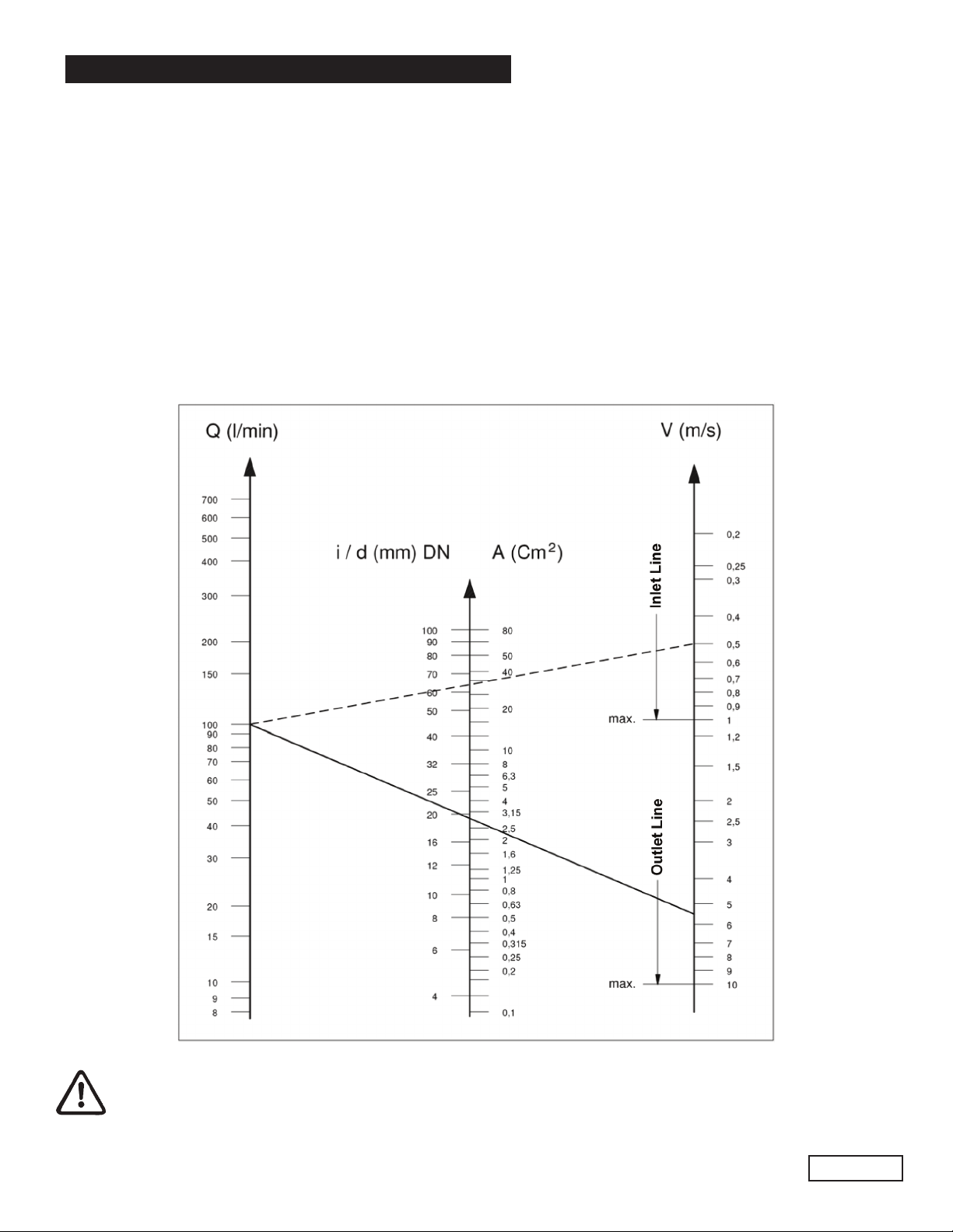
9.8 Internal Diameter of the Hose Line
To determine the internal diameter of the hose, please refer to the following diagram.
Inlet Hose
With a flow rate of ~26 GPM (99 l/mn) and water speed of 0.5 m/sec. The diagram line that connects the two scales
intersects the central scale, indicating the diameters, at a value of ~ 2.5 inch (65 mm).
Outlet Hose
With a flow rate of ~26 GPM (99 l/mn) and water speed of 5.5 m/sec. The diagram line that connects the two scales
intersects the central scale, indicating the diameters at a value of ~ .75 inch (19 mm).
Optimal speed to be obtained with the booster pump:
• Suction: ≤ 1 m/sec.
• Delivery: ≤ 5.5 m/sec.
A member of the Interpump Group
SK SERIES
The diagram does not take into account the hose and valve resistance, the pressure drop due to the pipe length,
the viscosity and the temperature of the pumped fluid. If necessary, contact our Customer Service Department.
Ref 300792 Rev.C
06-12
Page 14

GENERAL PUMP
A member of the Interpump Group
10. START-UP AND OPERATION
10.1 Preliminary Inspections
Before Start-up Be sure that:
The inlet line is connected and up to pressure (see Chapter 9) the pump must NEVER run dry.
1. The inlet line must be perfectly airtight.
2. All the On-Off valves between the pump and the feeding source are completely open. The outlet line must
discharge freely in order to allow the air in the pump to be expulsed easily, thus facilitating pump priming.
3. All fittings and connections must be correctly tightened.
4. Coupling tolerances on the pump/transmission axis (half-joint misalignment, Cardan inclination, belt
tightening, etc.) must remain within the limits indicated by the transmission Manufacturer.
5. The pump’s oil level must be verified using the correct dipsticks (position 1, fig 8).
SK SERIES
In case the pump has not run for a long period of time, recover the correct operation of the suction valves
by opening the three valve-lifting devices (see fig. 9). Be sure to reclose the valves before the pump
start-up.
10.2 Start-up
1. When starting the pump for the first time, check for the correct direction of rotation.
2. The pump must be started off-load.
3. Verify correct feeding pressure.
4. During operation, check that the rotating speed does not exceed the rated value.
5. Before putting the pump under pressure let it run for at least 3 minutes.
6. Before stopping the pump, release the pressure by acting on the adjustment valve or on any discharging device.
Ref 300792 Rev.C
Page 15
06-12

GENERAL PUMP
10.3 Cooling Circuit Seal Packing
During operation, some water from the cooling circuit seal packings will be discharged from port 1 (fig. 9). The drainage
from this circuit must be redirected to the inlet line upstream of the booster pump (fig. 9) or to the collection tank.
A member of the Interpump Group
SK SERIES
11. PREVENTIVE MAINTENANCE
To guarantee pump reliability and efficiency, comply with the maintenance intervals as indicated in the table below.
PREVENTIVE MAINTENANCE
EVERY 500 HOURS EVERY 1000 HOURS
Check oil level Change oil
Check / Replace:*
• Valves
• Valve seats
• Valve springs
• Valve guides
Check / Replace:
• H.P packings
• L.P. packings
* For replacement follow instructions contained in the repair manual.
Ref 300792 Rev.C
06-12
Page 16

GENERAL PUMP
12.
PUMP STORAGE
12.1 Inactivity for Lengthly Periods
If the pump is started for the first time after a long period of inactivity, before putting it into operation check the
oil level, inspect the valves as indicated in Chapter 10, and then follow the prescribed startup procedures.
12.2 Filling the Pump With An Anti-Corrosion Emulsion or Anit-freeze By Using An External Diaphragm Pump
As In The Layout Shown in Paragraph 9.6.
a) Close the filter draining, if open.
b) Be sure that the connecting hose is clean, spread with grease and connect it to the high pressure outlet port.
c) Fit a suction hose to the membrane pump. Open the pump suction connection and fit hose between it and the
membrane pump.
d) Fill the container with the solution/emulsion.
e) Put the free extremeties of the suction line and the high pressure outlet hose inside the container.
f) Start up the diphragm pump.
g) Pump the emulsion until it comes out of the high pressure hose.
h) Continue pumping for at least another minute; if needed, the emulsion can be reinforced by adding, for example,
Shell Donax
i) Stop the pump, remove the hose from the suction connection and close it with a plug.
j) Remove the hose from the high pressure outlet port. Clean, grease and plug both connections and the
hoses.
A member of the Interpump Group
SK SERIES
12.3 Hoses
a) Before greasing and protecting the hoses according to the previously described procedure, dry the connections
using compressed air.
b) Cover with polyethelene.
c) Do not wrap them too tightly; be sure there is no bending.
PRECAUTIONS AGAINST FREEZING
13.
In areas and periods of the year where there is risk of freezing, follow the instructions indicated in Chapter 12
(see paragraph 12.2).
In the presence of ice, in no case must the pump be started until the entire circuit has been completely
thawed out; not complying with this indication may cause serious damage to the pump.
WARRANTY TERMS
14.
The pump is guaranteed for a period of 5 years from the delivery date, with the exception of parts subject to wear. In
any case, please refer to the contract terms for other warranty conditions. The warranty is void if:
a) The pump has been used for purposes that differ from that agreed.
b) The pump has been fit with an electric or diesel engine with performance greater than that indicated in the table.
c) The required safety devices were un-adjusted or disconnected.
d) The pump was used with accessories or spare parts not supplied by General Pump.
e) Damage was caused by:
1) improper use
2) the non-observance of maintenance instructions
3) use not compliant with operating instructions
4) insufficient flow rate
5) faulty installation
6) incorrect positioning or sizing of the hoses
7) non-authorized design changes
8) cavitation
Ref 300792 Rev.C
06-12
Page 17

GENERAL PUMP
15.
TROUBLESHOOTING
The pump does not produce any noise at start-up:
• The pump is not primed and is running dry
• There is no water in the inlet line
• The valves are blocked
• The delivery line is closed and does not allow the air in the pump to be discharged
The pump pulses irregularly (knocking):
• Air suction
• Insufficient feeding
• Bends, elbows, fittings along the suction line obstruct the fluid’s passage
• The inlet filter is dirty or too small
• The booster pump, where provided, supplies insufficient pressure or flow rate
• The pump is not primed due to insufficient head or the delivery line is closed during priming
• The pump is not primed due to valve seizing
• Worn valves
• Worn pressure packings
• Incorrect operation of the pressure adjustment valve
• Transmission problems
The pump does not deliver the rated flow / is noisy:
• Insufficient feeding (see the causes listed above)
• RPM are less than the rated flow
• Excessive amount of water by-passed by the pressure adjustment valve
• Worn valves
• Leakage from the pressure packings
• Cavitation due to:
1) Wrong sizing of the suction hose/
undersized diameters
2) Insufficient flow rate
3) High water temperature
A member of the Interpump Group
SK SERIES
Insufficient pump pressure:
• The nozzle (or has become)too large
• Insufficient RPM
• Leakage from the pressure packings
• Incorrect operation of the pressure adjustment valve
• Worn valves
Overheated pump:
• The pump is overloaded (pressure or RPM exceed the rated values)
• Oil level is too low, or the oil is not of a suitable type, indicated in Chapter 7 (see paragraph 7.4)
• Incorrect alignment of the joint or pulleys
• Excessive inclination of the pump during operation
Pump vibrations or knocking:
• Air suction
• Incorrect operation of the pressure adjustment valve
• Valve malfunction
• Irregular drive transmission motion
Ref 300792 Rev.C
06-12
Page 18

GENERAL PUMP
16. EXPLODED VIEW AND PARTS LIST
A member of the Interpump Group
SK SERIES
Ref 300792 Rev.C
06-12
Page 19

GENERAL PUMP
Item Part # Description QTY.
1 F78120056 Manifold 1
36208060Valve Guide
2 F
94747500Spring, Ø 18x35 SK20, 22, 24
F
3
F94948900 Spring, Ø18.9x35, SK26, 28, 30 3
F36208356 Valve, Ø 20, 22, 24 3
4
F36208456 Valve, Ø 26, 28, 30 3
5 F93198700 Seal, Ø 36x41x3.8 3
36208156Valve Seat, Ø 20, 22, 24
F
6
F36208256 Valve Seat, Ø 26, 28, 30 3
7 F90390300 O-ring, Ø 60x2x2.62 3
36207856Valve Glide, Ø 20, 22, 24
F
8
F36207956 Valve Guide, Ø 26, 28, 30 3
94764000Spring, Ø 32x40, INOX, SK20, 22, 24
F
9
F94770500 Spring, Ø 41.5x44, INOX, SK26, 28, 30 3
78210020Cylinder Bushing
10F
F78060056 Liner, Ø 20, 22, 24 3
1
1
F78060156 Liner, Ø 26, 28, 30 3
F78211982 Plunger Bushing, Ø 20 3
78212082Plunger Bushing, Ø 22
F
F78212182 Plunger Bushing, Ø 24 3
2
1
78212282Plunger Bushing, Ø 26
F
78212382Plunger Bushing, Ø 28
F
78212482Plunger Bushing, Ø 30
F
13 F99382800 Screw, TCEI, M10x140 24
99523200Screw, TCEI, M16x180
14F
15 F90381800 O-ring, Ø 7.59x2.62 2
F78040601 Plunger Assembly, Ø 20 3
F78040701 Plunger Assembly, Ø 22 3
F78040801 Plunger Assembly, Ø 24 3
16
F78040901 Plunger Assembly, Ø 26 3
F78041001 Plunger Assembly, Ø 28 3
F78041101 Plunger Assembly, Ø 30 3
F90271200 H.P. Packing, Ø 20x36x17.9 3
F90273300 H.P. Packing, Ø 22x36x17.9 3
F90274400 H.P. Packing, Ø 24x36x17.9 3
17
F90274900 H.P. Packing, Ø 26x46x20.5 3
F90275900 H.P. Packing, Ø 28x46x18.5 3
F90277800 H.P. Packing, Ø 30x46x17.8 3
F78212568 Anti-extrusion Ring, Ø20 3
F78212668 Anti-extrusion Ring, Ø22 3
F78212768 Anti-extrusion Ring, Ø24 3
18
F78212868 Anti-extrusion Ring, Ø26 3
F78212978 Anti-extrusion Ring, Ø28 3
F78213068 Anti-extrusion Ring, Ø30 3
F78213160 Bushing Gasket, Ø 20 3
F78213260 Bushing Gasket, Ø 22 3
F78213360 Bushing Gasket, Ø 24 3
19
F78213460 Bushing Gasket, Ø 26 3
F78213560 Bushing Gasket, Ø 28 3
F78213660 Bushing Gasket, Ø 30 3
F90268900 L.P. Packing, Ø 20x28x6 3
F90271400 L.P. Packing, Ø 22x30x6 3
F90273900 L.P. Packing, Ø 24x32x6 3
20
F90274920 L.P. Packing, Ø 26x34x8 3
F90275200 L.P. Packing, Ø 28x36x6 3
F90276300 L.P. Packing, Ø 30x38x6 3
F78211356 Packing, Ø 20 3
F78211456 Packing, Ø 22 3
F78211556 Packing, Ø 24 3
21
F78211656 Packing, Ø 26 3
F78211756 Packing, Ø 28 3
F78211856 Packing, Ø 30 3
22 F90078000 Ring, INOX 3
F90387800 O-ring, Ø 39.34x2.62 (SK20, 22, 24) 3
23
F90388800 O-ring, Ø 48.89x2.62 (SK26, 28, 30) 3
24 F90391450 O-ring, Ø 78.87x2.62 6
25 F78210756 Gasket Support, Ø 20 3
A member of the Interpump Group
SK SERIES
temPart #
I
3
3
3
3
3
1
3
3
3
3
8
F78210856 Gasket Support, Ø 22 3
F78210956 Gasket Support, Ø 24 3
25
F78211056 Gasket Support, Ø 26 3
78211156Gasket Support, Ø 28
F
F78211256 Gasket Support, Ø 30 3
26 F99314600 Screw, TCEI, M8x50, UNI 30
90386500O-ring, Ø 29.82x2.62
27F
74213351Guard
28F
29 FF74150222 Open Inspection cover 1
30 F90167900 Ring, rad. Ø40x52x7 3
78213771Plunger Guide Oil Seal Cover
31F
32 F90391400 O-ring, Ø 72.69x2.62 3
33 F90450000 O-ring, Ø 266.06x5.34 2
34 F74150122 Closed Inspection Cover 1
35 F78150066 Plunger Guide Rod 3
36 F99191600 Screw, STEI, M6x30 3
97674000Elastic Pin, Ø 5x16
37F
99369700Screw, TE, M10x35
38F
39 F74050043 Plunger Guide 3
99441000Connecting Rod Screw, M12x1.25x87
40F
41 F78160020 Crankcase Cover 1
99305900Screw, TCEI, M8x20
42F
90417000O-ring, Ø 355.19x3.53
43F
78010013Pump Body
44F
45 F98195500 Plug, Ø 9x10 1
46 F90069700 Ring, 35 UNI 6
47 F97745000 Flinger Washer, Ø 35x64 3
48 F97597800 Oil Level Indicator 2
49 F78214200 Pressure Bushing 2
50 F78020035 Crankshaft 1
51 F99426800 Screw, TCEI, M12x25 8
52 F78213955 Bearing Flange 2
53 F91886200 Bearing 2
54 F78150200 Side Cover 2
55 F90392900 O-ring, Ø152.07x2.62 2
56 F90394000 O-ring, Ø183.62x2.62 2
57 F99368600 Screw, TCEI, M10x30 12
58 F78150013 Bearing Cover Door 3
59 F90931000 CONROD HEAD SEMI-BUSHING, UPPER 3
60 F90930000 CONROD HEAD SEMI-BUSHING, LOWER 3
61 F78030101 Connecting Rod Assembly 3
F10072735 Left Ring Gear, Z59 R2.95, Helicol 1
62
F10073135 Left Ring Gear, Z61 R3.389, Helicol 1
F10072835 Right Ring Gear, Z59 R2.95, Helicol 1
63
F10073235 Right Ring Gear, Z61 R3.389, Helicol 1
64 F97618500 Pin, Ø 8x18 2
65 F96751400 Washer, Ø 21.5x27x1.5 2
66 F98218300 Plug, G1/2”x13, Nickel 2
67 F98232800 Oil Plug 1
68 F91501000 Key 1
69 F93105000 2
70 F99183700 Screw, TCEI, M6x148.8 8
71 F96738000 Washer, Ø 17.5x23x1.5 1
72 F78214566 1
73 F96416400 Open Side Cover 1
F10073355 Pinion, Z20 R2.95, Helicol 1
74
F10073555 Pinion, Z18 R3.389, Helicol 1
75 F78150120 Open End Cover 1
76 F90172400 Ring, Rad., Ø 55x75x8, Viton 2
77 F78150320 Side PTO Bearing Cover, Left 1
78 F90391800 O-ring, Ø94.92x2.62 2
79 F91859700 Roller Bearing 4
80 F78214089 External Bearing Spacer 2
81 F78214189 Internal Bearing Spacer 2
82 F78214489 Bushing 2
83 F78214389 Bushing 2
84 F90358100 O-ring, Ø 8.73x1.78 8
85 F99308400 Screw, TCEI, M8x30 1
86 F78150420 Bearing Cover 1
87 F93174000 2
F93198900 Seal, Ø 46x51x3.8, SK26, 28, 30 3
88
F93198700 Seal, Ø 36x41x3.8, SK20, 22, 26 3
escription
D
TY.
Q
3
3
3
3
3
3
6
3
2
1
1
See next page for repair kits
Ref 300792 Rev.C
06-12
Page 20

GENERAL PUMP
REPAIR KITS
A member of the Interpump Group
SK SERIES
KIT NUMBER
Positions
Included
KIT NUMBER
Positions
Included
KIT NUMBER
Positions
Included
F2079 (SK20)
Plunger
Packing Kit
7, 15, 17, 18,
19, 20, 23, 24
F2085
(SK20, SK22, SK24)
Plunger
Packing Kit
5, 88 5, 88
F2087 (SK20)
Complete
Seals Kit
5, 7, 15, 17, 18,
19, 20, 23, 24,
27, 30, 32, 33,
43, 55, 56,76,
78, 84, 88
F2080 (SK22)
7, 15, 17, 18,
19, 20, 23, 24
F2088 (SK22)
5, 7, 15, 17, 18,
19, 20, 23, 24,
27, 30, 32, 33,
43, 55, 56,76,
Plunger
Packing Kit
F2086
(SK26, SK28, SK30)
Plunger
Packing Kit
Complete
Seals Kit
5, 7, 15, 17, 18,
78, 84, 88
F2081 (SK24)
Plunger
Packing Kit
7, 15, 17, 18,
19, 20, 23, 24
F2089 (SK24)
Complete
Seals Kit
19, 20, 23, 24,
27, 30, 32, 33,
43, 55, 56,76,
78, 84, 88
F2082 (SK26)
Plunger
Packing Kit
7, 15, 17, 18,
19, 20, 23, 24
F2090 (SK26)
Complete
Seals Kit
5, 7, 15, 17, 18,
19, 20, 23, 24,
27, 30, 32, 33,
43, 55, 56,76,
78, 84, 88
F2083 (SK28)
Plunger
Packing Kit
7, 15, 17, 18,
19, 20, 23, 24
F2091 (SK28)
Complete
Seals Kit
5, 7, 15, 17, 18,
19, 20, 23, 24,
27, 30, 32, 33,
43, 55, 56,76,
78, 84, 88
F2084 (SK30)
Plunger
Packing Kit
7, 15, 17, 18,
19, 20, 23, 24
F2092 (SK30)
Complete
Seals Kit
5, 7, 15, 17, 18,
19, 20, 23, 24,
27, 30, 32, 33,
43, 55, 56,76,
78, 84, 88
KIT NUMBER
Positions
Included
KIT NUMBER
Positions
Included
F2076 (All SK models)
Connecting Rod
Bushing Kit
59, 60
F2111
(SK20, SK22, SK24)
Inlet & Outlet
Valves Kit
2, 3, 4, 5, 6, 8, 9, 88 2, 3, 4, 5, 6, 8, 9, 88
(SK26, SK28, SK30)
F2112
Inlet & Outlet
Valves Kit
Ref 300792 Rev.C
06-12
Page 21

GENERAL PUMP
MAINTENANCE LOG
OIL CHANGE
GREASE
PACKING
REPLACEMENT
A member of the Interpump Group
SK SERIES
HOURS & DATE
PLUNGER
REPLACEMENT
VALVE
REPLACEMENT
GP Companies, Inc.
1174 Northland Drive
Mendota Heights, MN 55120
Phone: 651.686.2199 Fax: 800.535.1745
www.generalpump.com email: sales@gpcompanies.com
Ref 300792 Rev.C
06-12
Page 22
 Loading...