

SSHH
Owner’s Manual
• Installation
• Use
• Maintenance

GENERAL PUMP
INDEX
1. INTRODUCTION . . . . . . . . . . . . . . . . . . . . . . . . . . . . . . . . . . . . . . . . . . . . . . . . . .Page 3
2. SYMBOL DESCRIPTIONS . . . . . . . . . . . . . . . . . . . . . . . . . . . . . . . . . . . . . . . . . .Page 3
3. SAFETY . . . . . . . . . . . . . . . . . . . . . . . . . . . . . . . . . . . . . . . . . . . . . . . . . . . . . . . . .Page 3
3.1 General warnings for safe operation . . . . . . . . . . . . . . . . . . . . . . . . . . . . . . . .Page 3
3.2 High pressure unit safety requirements . . . . . . . . . . . . . . . . . . . . . . . . . . . . . .Page 3
3.3 Safety of operation . . . . . . . . . . . . . . . . . . . . . . . . . . . . . . . . . . . . . . . . . . . . . .Page 4
3.4 General procedures for high pressure lance/gun operation . . . . . . . . . . . . . . .Page 4
3.5 Safety of maintenance . . . . . . . . . . . . . . . . . . . . . . . . . . . . . . . . . . . . . . . . . . .Page 4
4. PUMP IDENTIFICATION . . . . . . . . . . . . . . . . . . . . . . . . . . . . . . . . . . . . . . . . . . . .Page 5
5. TECHNICAL FEATURES . . . . . . . . . . . . . . . . . . . . . . . . . . . . . . . . . . . . . . . . . . . .Page 5
6. DIMENSIONS AND WEIGHT . . . . . . . . . . . . . . . . . . . . . . . . . . . . . . . . . . . . . . . . .Page 5
7. GENERAL INFORMATION ABOUT SPECIFIC PUMP USE . . . . . . . . . . . . . . . . .Page 6
7.1 Water temperature . . . . . . . . . . . . . . . . . . . . . . . . . . . . . . . . . . . . . . . . . . . . . .Page 6
7.2 Maximum flow and pressure ratings . . . . . . . . . . . . . . . . . . . . . . . . . . . . . . . .Page 6
7.3 Lowest operating RPM . . . . . . . . . . . . . . . . . . . . . . . . . . . . . . . . . . . . . . . . . . .Page 6
A member of the Interpump Group
SH SERIES
8. CONNECTION AND PLUGS . . . . . . . . . . . . . . . . . . . . . . . . . . . . . . . . . . . . . . . . .Page 6
9. PUMP INSTALLATION . . . . . . . . . . . . . . . . . . . . . . . . . . . . . . . . . . . . . . . . . . . . . .Page 7
9.1 Positioning . . . . . . . . . . . . . . . . . . . . . . . . . . . . . . . . . . . . . . . . . . . . . . . . . . . .Page 7
9.2 Direction of rotation . . . . . . . . . . . . . . . . . . . . . . . . . . . . . . . . . . . . . . . . . . . . .Page 7
9.3 Water connections . . . . . . . . . . . . . . . . . . . . . . . . . . . . . . . . . . . . . . . . . . . . . .Page 7
9.4 Suction line . . . . . . . . . . . . . . . . . . . . . . . . . . . . . . . . . . . . . . . . . . . . . . . . . . . .Page 7
9.5 Filtration . . . . . . . . . . . . . . . . . . . . . . . . . . . . . . . . . . . . . . . . . . . . . . . . . . . . . .Page 8
9.6 Delivery time . . . . . . . . . . . . . . . . . . . . . . . . . . . . . . . . . . . . . . . . . . . . . . . . . . .Page 8
10. START UP AND RUNNING PROCEDURES . . . . . . . . . . . . . . . . . . . . . . . . . . . . .Page 8
10.1 Before start up . . . . . . . . . . . . . . . . . . . . . . . . . . . . . . . . . . . . . . . . . . . . . . . .Page 8
10.2 Starting up . . . . . . . . . . . . . . . . . . . . . . . . . . . . . . . . . . . . . . . . . . . . . . . . . . .Page 8
10.3 Water cooling system . . . . . . . . . . . . . . . . . . . . . . . . . . . . . . . . . . . . . . . . . . .Page 9
11. MAINTENANCE INSTRUCTIONS . . . . . . . . . . . . . . . . . . . . . . . . . . . . . . . . . . . . .Page 9
11.1 Crank mechanism maintenance . . . . . . . . . . . . . . . . . . . . . . . . . . . . . . . . . . .Page 9
11.2 Fluid end maintenance . . . . . . . . . . . . . . . . . . . . . . . . . . . . . . . . . . . . . . . . . .Page 10
11.3 Pumping unit maintenance . . . . . . . . . . . . . . . . . . . . . . . . . . . . . . . . . . . . . . .Page 11
12. SCREW CALIBRATION . . . . . . . . . . . . . . . . . . . . . . . . . . . . . . . . . . . . . . . . . . . . .Page 14
13. MAINTENANCE TOOLS . . . . . . . . . . . . . . . . . . . . . . . . . . . . . . . . . . . . . . . . . . . .Page 14
14. PUMP STOPPED FOR LONG TIME . . . . . . . . . . . . . . . . . . . . . . . . . . . . . . . . . . .Page 14
15. PRECAUTIONS AGAINST FREEZING . . . . . . . . . . . . . . . . . . . . . . . . . . . . . . . . .Page 14
16. EXPLODED VIEWS AND PARTS . . . . . . . . . . . . . . . . . . . . . . . . . . . . . . . . . . . . .Page 15
17. TROUBLE SHOOTING . . . . . . . . . . . . . . . . . . . . . . . . . . . . . . . . . . . . . . . . . . . . .Page 17
Page 2
GENERAL PUMP
A member of the Interpump Group
SH SERIES
1. INTRODUCTION
SH high pressure water plunger pumps have been
designed for long life industrial duties and provided they
are correctly installed and maintained will give long
trouble-free operation. Read and understand this
manual before using your pump; it contains the
necessary information for the correct installation, use and
maintenance as well as some practical suggestion for
trouble shooting.
Upon receipt of your pump, inspect for overall good
condition and that no items are missing. Any missing
item or damage should be reported before installing
and starting the pump.
2. SYMBOL DESCRIPTIONS
Warning
Potential Danger
Read carefully and understand
the manual before operating
the pump
Danger
High Voltage
Danger
Wear protective mask
Danger
Wear goggles
3. SAFETY
3.1 General warnings for safe operation
The misuse of a high pressure water unit and the nonobservance of the pump installation and maintenance
instructions may cause serious damages and/or injuries
to people or properties or both.
Any Manufacturer/Operator requested to assemble/use
a high pressure water unit should be competent to do so,
should have the necessary knowledge on every high
pressure component installed in the unit and on the
precautions to be taken in order to guarantee the largest
safety margins during operation. No precaution, so far
as is reasonably practical, should be left out in the
interest of safety, both from the Manufacturer and the
Operator.
3.2 High pressure unit safety requirements
1. A safety valve should be installed in any delivery line
and should be sized to discharge or by-pass the
entire pump flow rate
2. High pressure unit components, with particular regard
for those units working outside, should be adequately
protected against rain, frost and heat.
3. Electric components and wiring should be provided
with an adequate degree of protection, able to protect
them against spray coming from any direction. They
should also be suitable for working in a wet
environment.
4. High pressure hoses and any other accessory under
pressure should be sized in accordance with the
maximum unit working pressure and must always
work within the safety margins indicated by the nose/
accessory Manufacturer.
5. High pressure hose ends should be fastened to a
steady object in order to prevent them from
dangerous sweeping around, should they burst or
come off their end fittings.
6. Proper safety guards should be provided to
adequately cover transmission joints, pulleys, belts or
auxiliary drives.
Danger
Wear protective gloves
Danger
Wear protective boots
Page 3
GENERAL PUMP
3.3 Safety of operation
The access into the area when a high pressure unit is
working should be strictly prohibited to unauthorized
personnel. The area should be suitably enclosed and its
perimeter, so far as is reasonably practical, cordoned
off and proper warning notices displayed in prominent
positions.
Personnel authorized to enter that area should have been
previously trained to do so and informed of the risks
arising from failures, misuse and any foreseeable
circumstance which may occur during operation. Before
starting the pump unit and bringing it up to pressure the
Operator is requested to carry out the following checks:
1. Make sure that a correct water supply to the pump
is provided.
2. Make sure that water inlet filters are properly clean.
3. Electrical components and wiring, with special
emphasis on connections, junction boxes, switches
and supply cables should be free from external
damage (i.e. exposed and broken wires) and
adequately protected against water.
4. High pressure hose should not show apparent
external wear and the fittings at both ends should be
free from signs of erosion or corrosion.
5. Make sure that all fluids (lubricating oil for pump and
engine, cooling water, hydraulic fluids) are at proper
levels and in good condition.
6. Make sure the safety guards are in good condition.
The work should stop immediately and the pressure must
be released in the event that leakage becomes apparent
or if any person becomes aware of an change in condition
or any hazard existing or being introduced. Any failure
must be promptly reported and then checked personnel.
3.4 General procedures for high pressure gun/lance
operation
1. The Operator should take reasonable care for the
safety of himself and of other persons who may be
affected by his acts or omission at work. His actions
should always be governed by his good sense and
responsibility.
2. The Operator should wear suitable waterproof
protective clothing, having regard to the type of work
being undertaken. The clothing set should include
adequate hand protection, suitable boots able to
ensure proper grip on wet floors, helmet provided with
full face shield, waterproof garment providing full
cover to the Operator, including his arms.
As most water jets produce noise levels in excess of
A member of the Interpump Group
SH SERIES
90 dB(A) suitable ear protection is advised.
NOTE: it must be emphasized that whereas protective
clothing provides adequate protection against spray and
flying particles, it does not constitute complete protection
protection against the direct impact of the water jet.
Additional protections in the form of suitable metal shields
or barriers may be necessary for certain jetting operation.
3. In most jetting operations it is an accepted practice
to employ a team of Operators consisting of two
members at least, in order to provide mutual
assistance in case of need and to rotate their duties
in case of long and heavy work. While the first
Operator holds the gun, the second Operator attends
the pump unit, keeping close watch on the first
Operator for signs of difficulty or fatigue, and
watching the surrounding area for intrusion by other
persons or unsafe situations. If required, he will shut
off the pressure unit until it is safe to continue.
4. The area in which the work is to proceed should be
clear of loose items and debris to prevent
tripping and slipping hazards.
5. The water jet should be directed only and always
against the workpiece even during preliminary
operating tests prior to starting work.
6. Where applicable, proper side shields should be
suitable placed to safeguard personnel and
equipment against contact with grit or particles
removed by the water jet.
7. On no account must the Operator be distracted
during operation until the jet has been stopped.
Personnel having reason to enter the water jetting
area should wait until the jet is stopped and his
presence known.
8. Each team member must always be aware of the
actions and intentions of other team members in order
to prevent any dangerous misunderstanding occurring
during jetting operation.
9. The pump unit should not be started and brought up
to pressure unless each team member is in his
designated position, the nozzle directed to the
workpiece and the lance or gun securely held.
3.5 Safety of maintenance
Apart from the working pressure regulation no attempt
should be made to adjust any nut, hose, fitting, etc., while
that part of the system is under pressure. The pump
should be stopped and any pressure in the line released
prior to making any adjustments.
1. The high pressure water unit should be maintained in
accordance with the Manufacturer’s instructions.
2. The unit should be maintained only by competent
personnel
3. Service and maintenance should be carried out with
proper tools in order to prevent any damage on high
pressure connections and fittings.
4. Use of other than original spare parts is strictly
forbidden.
Page 4
GENERAL PUMP
A member of the Interpump Group
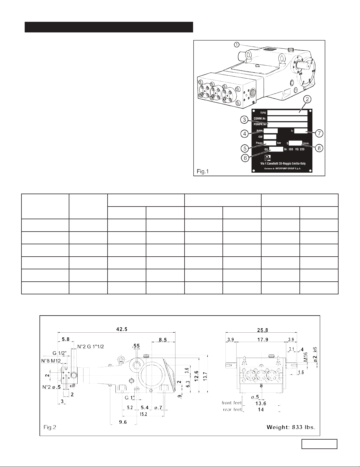
4. PUMP IDENTIFICATION
Each pump is fitted with a rating plate (see Fig. 1)
containing the following information:
2. pump model and version
3. serial number
4. max RPM
5. max operating pressure (bar)
6. oil capacity (ltr) and oil specification
7. gear box ratio
8. max flow rate (l/min)
Pump model, pump version and serial number should
be specified when ordering spare parts. Should the pump
be modified (i.e by changing the original version) than
any change should be mentioned on the rating plate for
future reference.
5. TECHNICAL FEATURES
SH SERIES
FLOW RATE PRESSURE POWER
MODEL RPM
GPM l/min PSI Bar Hp kW
SH20 1750/1500 11.6/11.3 44/43 20,300 1400 160 117
SH22 1750/1500 14.0/13.7 53/52 15,950 1100 151 110
SH24 1750/1500 16.6/16.3 63/62 13,800 950 155/153 114/112
SH26 1750/1500 19.5/19.2 74/72 11,600 800 153/110 113/110
SH28 1750/1500 22.7/22.3 86/84 10,150 700 156/113 115/113
SH30 1750/1500 25.9/25.6 98/96 8,700 600 152/110 112/110
6. DIMENSIONS AND WEIGHT
Page 5
GENERAL PUMP
A member of the Interpump Group
SH SERIES
7. GENERAL INFORMATION ABOUT PUMP
USE
The SH pump has been designed to pump fresh filtered
water at room temperature.
7.1 Water temperature
The max water temperature is 30oC (86oF
7.2 Max flow and pressure ratings
The performance data indicated in the catalog and on the
rating plate refer to the maximum performance of the
pump. The use of the pump below the rated performances
does not allow the drop in power absorbed to be balanced
by altering the pressure or volume of the pump above its
maximum value.
7.3 Lowest operating RPM
The lowest operating speed of the crankshaft for all SH
pumps (all versions) is 350 RPM.
)
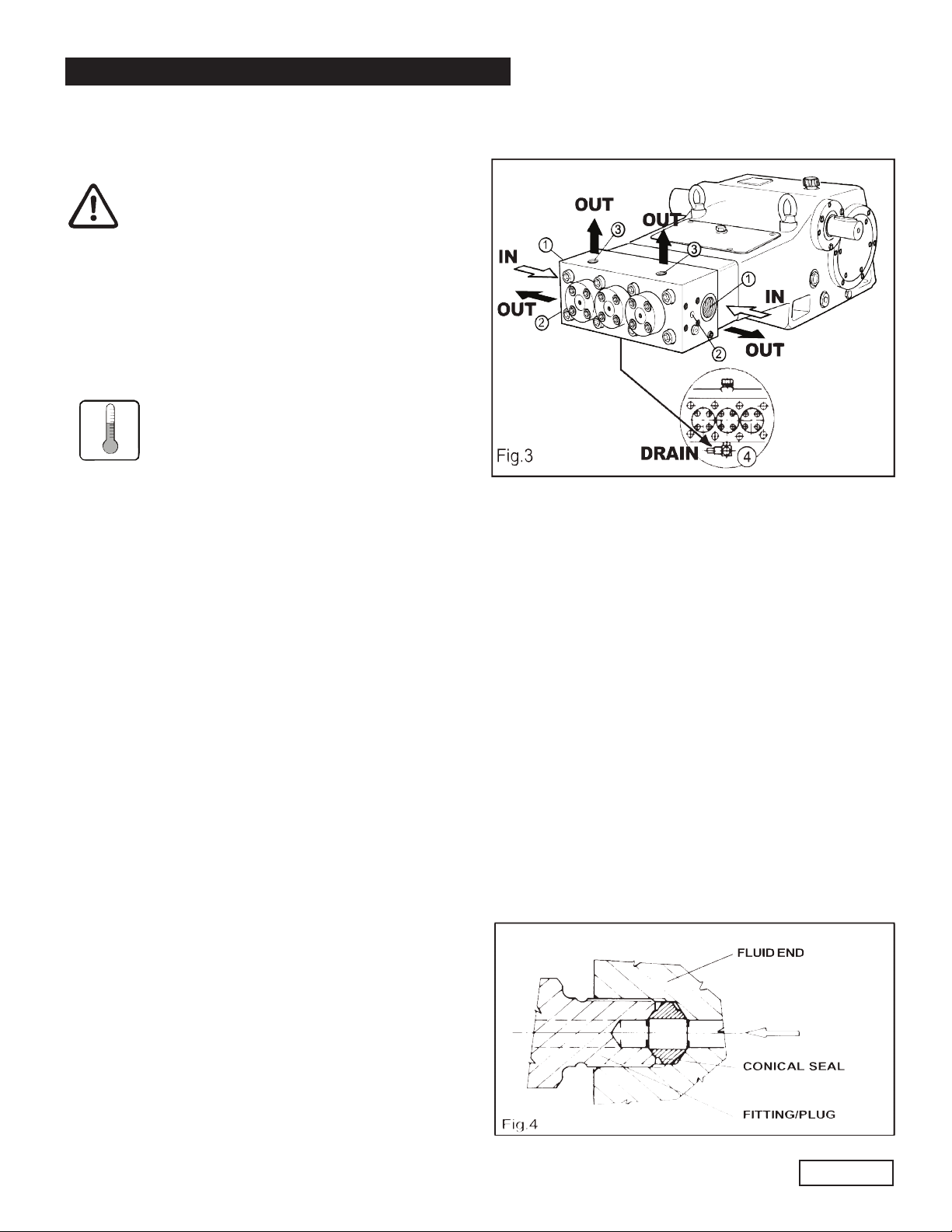
8. CONNECTIONS AND PLUGS
SH pumps are provided with (Fig. 3):
1 - 2 inlet ports IN G 1-1/2”
Suction line connection to either inlet port is
acceptable, the port not being used should be
sealed with the correct plug.
2 - 2 outlet ports OUT Ø 14mm”
3 - 2 outlet ports OUT Ø G 1/2” (designed for pressure
gauge and safety valve only)
4 - 1 hole DRAIN provided with quick coupling for
connection with Rilsan air hose Ø 10 mm; it collects
the water drainage from the cooling system and
should be connected back to the suction line BEFORE
the feed pump.
The SH pump is supplied with 4 conical seals (Fig 4)
made of stainless steel and designed to provide total
sealing of the outlet connections. They must be used in
either the outlet ports of the head or in the outlet ports
of the optional outlet mounting flanges. The conical
seals should be replaced at any disassembling and
not re-used.
Page 6

GENERAL PUMP
A member of the Interpump Group
9. PUMP INSTALLATION
9.1 Positioning
The pump should be installed flat on a rigid base by
means of the four Ø 19mm feet. The base should
be rigid enough to avoid any misalignment or flexing of the
pump/transmission coupling axis due to the torque
involved during operation.
9.2 Direction of rotation
Fig. 5 shows the correct direction of rotation looking at the
pump from the fluid end side. Two arrows stamped on the
crankcase nearby the crankshaft provide the information
as well.
9.3 Water connections
In order to isolate the high pressure equipment from the
pump vibrations it is suggested, where applicable, to use
flexible hoses for both suction and delivery lines at least
for the first length.
9.4 Suction Line
Sh pumps require an inlet pressure at the suction port
of at least 73 PSI up to 100 PSI. The feeding pump should
be of a centrifugal type , supply at least twice the rated SH
pump flow rate at the above required pressures in any
working condition at any pump soeed. The feed pump
should be operated independently from the plunger pump.
The SH pump should be started only when the inlet
pressure is at least 73 PSI. A pressure switch to control the
correct inlet pressure should always be installed in the
suction line after the filters.
SH SERIES
9.4 Suction line
For the correct pump operation make sure that the
suction line meets with the following requirements:
1. Internal diameter should be at least 1.5”, in any
point, possibly larger depending on the drop in
pressure due to the length and shape of the line.
2. Should be as straight as possible minimizing changes
in size and direction and positioned in such a way
to allow air pockets and bubbles to escape.
3. Should be perfectly airtight.
4. Should be completely free from 90oelbows, diameter
reductions, counter slopes, “T” connections and
should not be connected to other pipelines.
5. Should positioned in such a way to prevent the pipe
emptying after the pump stops.6. Do not use high
pressure flexible hoses for the suction line.
6. Do not use high pressure flexible hoses for the
suction line.
7. Do not use high pressure hydraulic fittings like 90
elbows, high pressure adapters, high pressure 3 or
4 way nipples and so on.
8. Do not install any kind of detergent injector along the
suction line.
9. Do not install standing valves, check valves or other
kind of one-way valves.
10. Make sure that the feed tank capacity and the water
minimum level do not give rise to turbulence at the
tank outlet port, which, in turn, might create
cavitation at the pump.
11. Do not connect the by-pass line from the valve directly
to the pump suction line.
12. The water flow from the valve should be directed back
in the tank. Make sure that the by-pass and tank
feeding flows to not give rise to turbulence at the
tank outlet port, which, in turn, might create
cavitation at the pump. Proper baffle plates should
be provided inside the tank.
13. Before connecting the suction line to the pump inlet
port make sure the pipe is perfectly clean inside.
o
Page 7

GENERAL PUMP
A member of the Interpump Group
SH SERIES
9.5 Filtration
SH pumps require 10 to 20 microns water filtration degree.
For a correct filtration system three individual
filter units should be provided and positioned as shown
in Fig. 6.
The filters should be installed as close as possible to the
pump, allow easy inspection and have the following
specifications:
a. Capacity of each filter should be at least three times
the rated pump flow rate.
b. Filter port diameters should not be smaller than the
pump inlet ports.
c. Filtration degree of each filter should be as follows:
Filter 1: 250 microns
Filter 2: 70 - 100 microns
Filter 3: 10 - 20 microns
IMPORTANT NOTE: in order to properly safeguard the
pump it is very important to plan cleaning of the filter
with a frequency depending on the water quality,
filtration degree and number of hours of each
application.
9.6 Delivery line
For a correct delivery line comply with the following
instructions:
1. The first length of delivery hose should be flexible in
order to isolate the pump vibrations from the
rest of the system.
2. Use only high pressure hoses and fittings able to
guarantee the largest possible safety margins in
any working conditions.
3. A suitable relief valve should be installed in the
delivery line.
4. Use glycerine filled pressure gauges, as the most
suitable for pulsating loads.
5. When designing the delivery line, take into proper
account the unavoidable drop in pressure, due to
its length and size.
10. START UP AND RUNNING PROCEDURES
10.1 Before start up
Before start up make sure that the following conditions
have been complied with:
1. Suction line should be connected: the pump must
never run dry.
2. Suction line must be perfectly air-tight.
3. Any ON-OFF valve in between the pump and water
source should be open and make sure the water
gets into the pump freely.
4. Set the pressure line in dump mode in order to let
the air in the pump get out easily thus facilitating
the pump priming.
5. Make sure all suction/delivery line connections are
fully tightened.
6. Joint alignment, belt tightening and PTO shaft
inclination tolerances should remain within the
values indicated by the transmission Manufacturer.
7. Make sure the oil level is correct.
Note: in case the pump has not run for a long period of
time check the suction and delivery valves for scaling
(see paragraph 11.2).
10.2 Starting up
1. Pump and motor/engine should start offload, set the
regulating valve to zero or set the pressure line in
dump mode by means of proper dumping devices.
2. Make sure the pump starts only when the correct
inlet pressure is provided.
3. When starting the pump up for the first time or after
every wiring re-connection check for the proper
direction of rotation.
4. Check that the rotating speed does not exceed the
rated value.
5. Before putting the pump under pressure let it run for
some time until the oil flows freely.
6. Before stopping the pump release the pressure from
the system by operating the dump device or by
releasing the regulating valve and reduce RPM to a
minimum (diesel applications).
Page 8

GENERAL PUMP
A member of the Interpump Group
SH SERIES
10.3 Water cooling system
During operation the cooling water is drained out of the
pump though the port (4, Fig. 7) located underneath
the pump head. The cooling water line should be
connected to the inlet line BEFORE the feed pump as
shown below.
11. MAINTENANCE INSTRUCTIONS
11.1 Crank mechanism maintenance.
Check oil level though the oil level indicator (1, Fig. 8)
at least on a weekly basis.
If necessary, top up from the oil plug 3, Fig. 8.
Check the oil when cold and change the oil when still
hot (pump still at working temperature.).
In order to drain the oil from the pump remove the
magnetic plug 2, Fig. 8.
At every oil change clean the magnetic plug 2, Fig. 8 and
check the lower cover of Fig. 7 for grease
sediments or deposits.
OIL CHANGES Hours Qty.
Oil
Type
First Change 50
Subsequent
Changes
Oil should be changed at least once a year.
Recommended oils:
BRAND TYPE
AGIP ACER 220
ARAL MOTANOL HP 220
AVIA AVILUB RSL 220
BP ENERGOL HL 220
CASTROL ALPHA ZN 220
ESSO NUTO 220
FINA SOLNA 220
IP HYDRUS 220
MOBIL DTE OIL BB
SHELL TELLUS C 220
TEXACO REGOL OIL 220
TOTAL CORTIS 220
500
3.1
quarts
ISO
220
Page 9

GENERAL PUMP
11.2 Fluid end maintenance
The fluid end does not require periodical maintenance.
Service operations are limited to valve inspection
and/or replacement, when necessary.
In order to have access to the delivery valves loosen the
12 valve cover screws (1, Fig. 9) and remove the covers.
A member of the Interpump Group
SH SERIES
Remove the pump head. (Fig. 12)
Once removed take out the delivery valve guide with the
spring and valve poppet. AN M10 threaded bolt to be used
as a simple extractor would help the operation (see
Fig. 10).
Loosen and remove the 8 head screws (1, Fig. 11).
When removing the head from the pump pay attention
to the valve seats (1, Fig 13) and the suction valve
poppets (2, Fig. 13) which may fall off the head. Check
the cooling system orifices of the head (see arrows) and
the relevant white tips (3, Fig. 3) for deposits or sediments
that may prevent cooling water from flowing through.
Remove the valve seats (1, Fig 14) from the head, check
them for wear and replace if necessary.
BEFORE REPOSITIONING THE VALVE UNITS BACK
IN PLACE CLEAN AND PERFECTLY DRY ALL VALVE
HOUSINGS INSIDE THE HEAD.
VALVE RINGS (2, FIG. 14) AND ALL O-RINGS SHOULD
BE REPLACED AT EVERY INSPECTION.
Page 10

GENERAL PUMP
A member of the Interpump Group
SH SERIES
Reassemble valves and head back in place
by following the disassembling steps in the
opposite sequence and use a torque wrench
at the following settings for valve cover
screws and head screws:
-Valve cover screw: 144.6 ft. lbs.
-Head screws: 397.8 ft. lbs.
NOTE:
In order to facilitate reassembling operation use our tool
1, Fig. 15 (p/n F200030140 for SH20-24, p/n F200030130
for SH26-30) or equivalent, able to hold the valve seat and
valve poppet in place when mounting the head on the
pump (see arrow Fig. 16).
11.3 Pumping unit maintenance.
The only maintenance operation required for the pumping
unit is the visual check of the amount of water drained out
by the cooling system through the hole provided
underneath the head (Fig. 7, page 9). It clearly shows
the pressure packing state of wear. Pressure packings
should be replaced when vibration and/or drop in the
operating pressure start to occur during operation.
Remove the eight head screws (1, Fig. 17).
Remove the pump head (see chapter 11.2).
Take out the collector (1, Fig. 19).
Page 11

GENERAL PUMP
A member of the Interpump Group
SH SERIES
Remove the upper cover (1, Fig. 20).
Once head and collector are removed the cylinders (1,
Fig.21) are free to be taken out of the pump body. Tapping
the cylinders all around with a plastic hammer helps to
loosen them from possible scaling or deposit
accumulated during operation.
Remove the seeger (1, Fig. 23).
Remove the rear support 1, the rear seal 2 and the
o-ring (3, Fig. 24).
Once the cylinders are removed, loosen the plungers and
check them for wear (Fig 22). Replace if necessary.
Insert a pin of adequate dimensions and smartly tap
until the complete pressure packing set is out (Fig. 25).
Replace pressure packing set at every inspection.
Page 12

GENERAL PUMP
Fit each new component of the pressure packing set in
the cylinder making sure of the correct order as shown
in Fig 26:
1. Packing bushing
2. Packing ring
3. Back packing
4. Pressure Packings
5. Pressure packing retaining bushing
A member of the Interpump Group
SH SERIES
The new rear seal should be mounted with the larger
diameter side first in, as shown in Fig. 28.
Reassemble the pump by following the
disassembling steps in the opposite sequence
and use a torque wrench for the screws listed
below:
-Plunger screws: 72.3 ft. lbs.
-Head screws: 397.8 ft. lbs.
-Valve cover screws: 144.6 ft. lbs.
Each pressure packing set component should fit tight in
the cylinders. A pin of adequate dimension (1, Fig. 27)
helps in guiding each component straight and aligned all
the way down the cylinder.
Page 13

GENERAL PUMP
A member of the Interpump Group
SH SERIES
12. SCREW CALIBRATION
Screw calibration is to be carried out by
means of a torque wrench only:
DESCRIPTION Ft. Lbs. N-m Kgm.
Valve cover
screws
Head Bolts 397.8 539.3 55
Plunger bolts 72.3 98 10
Connecting Rod
Screws
144.6 196.1 20
54.2 73.5 7.5
13. MAINTENANCE TOOLS
The following tools are designed to
facilitate mounting and dismounting
operations of some pump components:
for disassembling:
-cylinder extractor F200000190
for assembling:
-head/valve seat tool SH20-24 F200030140
-head/valve seat tool SH26-30 F200030130
15. PRECAUTIONS AGAINST FREEZING
In the risk of freezing the following
precautions should be taken:
- After use drain the entire suction and delivery lines
(filter included) by means of discharging devices,
provided and positioned specifically for this purpose
along the lowest point of the lines.
- Run the pump only for a few seconds in order to
drain the water collected inside the fluid end.
Or when applicable
- Add a recommended amount of anti-freeze into the
water tank and run the pump until the anti-freeze
works all through the system.
14. PUMP STOPPED FOR LONG TIME
Before starting the pump for the very first
time after a long period from the date of
shipment check for the correct oil level,
check the valves as indicated in chapter
11 and then comply with the starting
procedures indicated in chapter 10. When
a long inactivity is scheduled drain the
entire suction and delivery line and then
run the pump dry only for a few seconds
in order to drain out the water collected
inside the fluid end.
If a pump is frozen or appears frozen ON NO ACCOUNT
SHOULD THE PUMP BE OPERATED until the entire
system has been thawed out.
Page 14

GENERAL PUMP
16. EXPLODED VIEW AND PARTS LIST
A member of the Interpump Group
SH SERIES
Page 15

GENERAL PUMP
Item Part # Description QTY.
1 F881010133 O-ring Ø 183.82 x 2.62 2
010100070Left bearing support
2 F
030000010Bearing bushing retainer flange
3 F
4 F881010132 O-ring Ø 152.07 x 2.62 2
5 F871121152 Screw M8 x 20 23
6 F063400280 Bearing cover 2
871131102Screw M12 x 25
7 F
8 F030000020 Bearing bushing 2
9 F811111017 Bearing 2
10 F871125154 Screw M10 x 30 12
11 F871115152 Screw M6 x 14 14
12 F040400050 Lower cover 1
13 F080600030 Lower cover gasket 1
14 F872043008 Aluminum washer Ø 1” 2
15 F821203006 Plug G 1” 2
16 F801053012 Oil level indicator G 1” 2
17 F872043002 Aluninum washer G 1/2” 2
18 F801057002 Magnetic plug G 1/2” 2
19 F063400240 Back cover 1
20 F080600010 Back cover gasket 1
21 F060100160 Crankcase 1
22 F881010116 O-ring Ø 29.82 x 2.62 1
23 F801054027 Oil filling plug G 1” 1
24 F872026003 Eye bolt M16 2
25 F030000030 Eye bolt spacer 2
26 F080600020 Upper cover gasket 2-4
27 F040400030 Upper cover 1
28 F801056002 Venting plug G 1/2” 1
29 F040400070 Crankshaft end cap 1
30 F881080026 Oil seal Ø 55 x 75 x 10 2
31 F871121105 Screw M8 x 30 8
32 F063400300 Left bearing cover 1
33 F881010130 O-ring Ø 94.92 x 2.62 2
34 F811101019 Bearing 4
35 F031000020 Internal bearing spacer 2
36 F031000010 External bearing spacer 2
37 F061000000 Lubricating bushing 2
38 F031400000 Lubricating cone 2
39 F872097013 Pinion key 1
40 F052000020 Pinion 1500 RPM 1
F052000050 Pinion 1750 RPM 1
41 F063400310 Right bearing cover 1
42 F010100080 Right bearing support 1
43 F052000000 Gear 1500 RPM 1
F052000030 Gear 1750 RPM 1
44 F881010003 O-ring Ø 8.73 x 1.78 2
45 F050000060 Crankshaft 1
46 F052000010 Gear 1500 RPM (Z59 right toothing) 1
F052000040 Gear 1750 RPM (Z61 right toothing) 1
47 F034000000 Connecting rod pin 3
48 F035000070 Connecting rod screw 6
49 F872067006 Locking washer Ø 12 6
50 F023300000 Brass bearing 3
51 F002000000 Crankshaft pin 2
52 F250000030 Connecting rod assembly 3
53 F250001110 Piston assembly 3
54 F872142015 Retainer pin Ø 5 x 36 3
55 F071000050 Wrist pin Ø 35 3
56 F881081001 Oil seal Ø 35 x 47 x 8.5 Spec. 3
57 F881010128 O-ring Ø 72.69 x 2.62 3
58 F063400420 Oil seal cover 3
59 F030000070 Wiper bushing 3
60 F041200010 Wiper 3
61 F031200440 Wiper spacer 3
62 F124200220 Plunger SH20 3
F124200230 Plunger SH22 3
F124200240 Plunger SH24 3
F124200260 Plunger SH26 3
A member of the Interpump Group
Item Part # Description QTY.
1
2
8
REPAIR KITS
Item SH20 SH22 SH24 SH26 SH28 SH30
65-66-68-69-71-73-76-97-98 F1111 F1112 F1113 F1114 F1115 F1116
81-83-97-98 F1117 F1118
1-4-13-17-20-22-26-28-30-33
44-49-54-56-57-65-66-68-69
71-73-76-81-83-89-97-98
F1119 F1120 F1121 F1122 F1123 F1124
SH SERIES
62 F124200250 Plunger SH28 3
124200270Plunger SH30
F
872071530Seeger Ø 52 SH20-22-24
63F
F872071533 Seeger Ø 58 SH26-28-30 3
64 F031300170 Scraper ring SH20 3
F031300180 Scraper ring SH22 3
031300220Scraper ring SH24
F
F031300210 Scraper ring SH26 3
F031300200 Scraper ring SH28 3
F031300190 Scraper ring SH30 3
65 F881010122 O-ring Ø 47.30 x 2.62 SH20-22-24 3
F881010140 O-ring Ø 52.07 x 2.62 SH26-28-30 3
66 F881030009 Seal ring SH20 3
F881030010 Seal ring SH22 3
F881030040 Seal ring SH24 3
F881030041 Seal ring SH26 3
F881030012 Seal ring SH28 3
F881030013 Seal ring SH30 3
68 F083500020 Cooling system tip 3
69 F881010142 O-ring Ø 75.87 x 2.62 6
70 F162200050 Cylinder SH20 3
F162200060 Cylinder SH22 3
F162200070 Cylinder SH24 3
F162200080 Cylinder SH26 3
F162200090 Cylinder SH28 3
F162200010 Cylinder SH30 3
71 F881010143 O-ring Ø 82.22 x 2.62 3
72 F064400020 Collector 1
73 F881010100 O-ring Ø 9.19 x 2.62 9
76 F205000050 Pressure packing kit SH20 3
F205000060 Pressure packing kit SH22 3
F205000070 Pressure packing kit SH24 3
F205000080 Pressure packing kit SH26 3
F205000090 Pressure packing kit SH28 3
F205000100 Pressure packing kit SH30 3
78 F031500190 Pressure packing retaining bushing SH20 3
F031500200 Pressure packing retaining bushing SH22 3
F031500210 Pressure packing retaining bushing SH24 3
F031500220 Pressure packing retaining bushing SH26 3
F031500230 Pressure packing retaining bushing SH28 3
F031500240 Pressure packing retaining bushing SH30 3
79 F090200180 Suction valve spring SH20-22-24 3
F090200200 Suction valve spring SH26-28-30 3
80 F082200230 Suction valve poppet SH20-22-24 3
F082200270 Suction valve poppet SH26-28-30 3
81 F080500170 Ring (Suction side) SH20-22-24 3
F080500200 Ring (suction side) SH26-28-30 3
82 F081200570 Valve seat SH20-22-24 3
F081200650 Valve seat SH26-28-30 3
83 F080500160 Valve seat ring (delivery side) 3
84 F082200220 Delivery valve poppet SH20-22-24 3
F082200260 Delivery valve poppet SH26-28-30 3
85 F090200170 Delivery valve spring SH20-22-24 3
F090200210 Delivery valve spring SH26-28-30 3
86 F021300390 Delivery valve guide 3
87 F208006710 Valve assembly SH20-22-24 3
F208006720 Valve assembly SH 26-28-30 3
88 F821203100 Plug G 1/8” 4
89 F872042000 Aluminum washer Ø 10 4
91 F801203030 Quick coupling G 3/8” 1
94 F871151932 Screw M20 x 300 Spec. 8
95 F063200150 Valve cover 3
96 F871135953 Screw M14 x 45 Spec. 12
97 F010500050 Anti-extrusion ring 3
98 F881010207 O-ring Ø 17 x 3.53 3
99 F064200320 Manifold 1
100 680086 Conical seal G 1/2” 2
Page 16
3
3
3

GENERAL PUMP
17. TROUBLE SHOOTING
A member of the Interpump Group
SH SERIES
THE PUMP DOES NOT PRODUCE ANY
NOISE: the pump is not primed
and is running dry!
- No water in the inlet line
- The valves are blocked
- The pressure line is closed and does
not allow the air to get out the fluid
end.
THE PUMP KNOCKS:
- Air suction.
- Insufficient feeding:
- bends, elbows and fittings along the
suction line throttle the amount of
water which passed through.
- too small inlet filter.
- dirty inlet filter.
- the feeding pump, where provided is
not of the suitable type or provides
insufficient pressure or volume.
- The pump is not primed due to
insufficient feeding or the delivery line
is closed during start up.
- The pump is not primed because some
valves are stuck (i.e pump inactivity
for long time).
- Jammed or worn out valves.
- Worn out pressure packings.
- The pressure regulating valve does not
work properly.
- Clearance in the drive system.
- RPM are higher than rated.
THE PUMP DOES NOT DELIVER THE
RATED VOLUME:
- Insufficient feeding (due to the cause
listed above).
- RPM are less than rated.
- Excessive amount of water by-passed
by the pressure regulating valve.
- Worn out valves
- Excessive leakage from pressure
packings
INSUFFICIENT PUMP PRESSURE:
- The nozzle is (or has become) too large.
- RPM are less than rated
- Excessive leakage from pressure
packings
- Excessive amount of water by-passed
by the pressure regulating valve or
faulty valve operation.
- Worn out valves.
EXCESSIVE WATER LEAKAGE FROM
THE PUMP:
- Pressure packing are excessively worn
out (due to normal wear or excessive
cavitation).
- Worn out plungers
OVERHEATED PUMP:
- The direction of rotation is not correct.
- Pump is overloaded (pressure or RPM
over the rated values).
- The oil level is too low or the oil is not of
a suitable type or fully used
- Water in the oil
- Excessive belt tension or incorrect
alignment of the joint (where provided).
- Excessive inclination of the pump
during operation.
PIPE VIBRATIONS OR KNOCKING:
- Air suction.
- The pressure regulating valve does not
work properly.
- The by-pass line is undersized.
- Jammed up valves.
- Drive transmission motion is irregular.
Page 17

GENERAL PUMP
MAINTENANCE LOG
OIL CHANGE
GREASE
PACKING
REPLACEMENT
A member of the Interpump Group
SH SERIES
HOURS & DATE
PLUNGER
REPLACEMENT
VALVE
REPLACEMENT
GP Companies, Inc.
1174 Northland Drive
Mendota Heights, MN 55120
Phone:651.686.2199 Fax: 800.535.1745
www.generalpump.com email: sales@gpcompanies.com
Ref 300032 Rev.C
08/07
Page 18
 Loading...