

General Pump LK Owner Manual
LLKK
Owner’s Manual
• Installation
• Use
• Maintenance
LK50/55/60
LK36/40/45

GENERAL PUMP
INDEX
1. INTRODUCTION . . . . . . . . . . . . . . . . . . . . . . . . . . . . . . . . . . . . . . . . . . . . . . . . . .Page 4
2. SYMBOL DESCRIPTIONS . . . . . . . . . . . . . . . . . . . . . . . . . . . . . . . . . . . . . . . . . .Page 4
3. SAFETY . . . . . . . . . . . . . . . . . . . . . . . . . . . . . . . . . . . . . . . . . . . . . . . . . . . . . . . . .Page 4
3.1 General safety warnings . . . . . . . . . . . . . . . . . . . . . . . . . . . . . . . . . . . . . . . . . .Page 4
3.2 High pressure unit safety requirements . . . . . . . . . . . . . . . . . . . . . . . . . . . . . .Page 4
3.3 Safety during operation . . . . . . . . . . . . . . . . . . . . . . . . . . . . . . . . . . . . . . . . . .Page 5
3.4 General procedures for using nozzles . . . . . . . . . . . . . . . . . . . . . . . . . . . . . . .Page 5
3.5 Safety during unit maintenance . . . . . . . . . . . . . . . . . . . . . . . . . . . . . . . . . . . .Page 5
4. PUMP IDENTIFICATION . . . . . . . . . . . . . . . . . . . . . . . . . . . . . . . . . . . . . . . . . . . .Page 6
5. TECHNICAL CHARACTERISTICS . . . . . . . . . . . . . . . . . . . . . . . . . . . . . . . . . . . .Page 6
6. DIMENSIONS AND WEIGHTS . . . . . . . . . . . . . . . . . . . . . . . . . . . . . . . . . . . . . . .Page 7
7. INFORMATION REGARDING PUMP USE . . . . . . . . . . . . . . . . . . . . . . . . . . . . . .Page 8
7.1 Water temperature . . . . . . . . . . . . . . . . . . . . . . . . . . . . . . . . . . . . . . . . . . . . . .Page 8
7.2 Maximum flow and pressure values . . . . . . . . . . . . . . . . . . . . . . . . . . . . . . . . .Page 8
7.3 Lowest operating RPM . . . . . . . . . . . . . . . . . . . . . . . . . . . . . . . . . . . . . . . . . . .Page 8
7.4 Recommended lubricant types and Manufacturers . . . . . . . . . . . . . . . . . . . . .Page 8
A member of the Interpump Group
LK SERIES
8. PORTS AND CONNECTIONS . . . . . . . . . . . . . . . . . . . . . . . . . . . . . . . . . . . . . . . .Page 10
9. PUMP INSTALLATION . . . . . . . . . . . . . . . . . . . . . . . . . . . . . . . . . . . . . . . . . . . . . .Page 11
9.1 Installation . . . . . . . . . . . . . . . . . . . . . . . . . . . . . . . . . . . . . . . . . . . . . . . . . . . . .Page 11
9.2 Direction of rotation . . . . . . . . . . . . . . . . . . . . . . . . . . . . . . . . . . . . . . . . . . . . .Page 11
9.3 Hydraulic connections . . . . . . . . . . . . . . . . . . . . . . . . . . . . . . . . . . . . . . . . . . .Page 12
9.4 Pump feeding . . . . . . . . . . . . . . . . . . . . . . . . . . . . . . . . . . . . . . . . . . . . . . . . . .Page 12
9.5 Inlet line . . . . . . . . . . . . . . . . . . . . . . . . . . . . . . . . . . . . . . . . . . . . . . . . . . . . . .Page 12
9.6 Filtration . . . . . . . . . . . . . . . . . . . . . . . . . . . . . . . . . . . . . . . . . . . . . . . . . . . . . .Page 13
9.7 Outlet line . . . . . . . . . . . . . . . . . . . . . . . . . . . . . . . . . . . . . . . . . . . . . . . . . . . . .Page 14
9.9 Internal diameter of hose . . . . . . . . . . . . . . . . . . . . . . . . . . . . . . . . . . . . . . . . .Page 15
10. START UP AND OPERATION . . . . . . . . . . . . . . . . . . . . . . . . . . . . . . . . . . . . . . . .Page 16
10.1 Preliminary inspections . . . . . . . . . . . . . . . . . . . . . . . . . . . . . . . . . . . . . . . . . .Page 16
10.2 Starting up . . . . . . . . . . . . . . . . . . . . . . . . . . . . . . . . . . . . . . . . . . . . . . . . . . .Page 17
11. PREVENTATIVE MAINTENANCE . . . . . . . . . . . . . . . . . . . . . . . . . . . . . . . . . . . .Page 17
12. STOPPING THE PUMP FOR LONG PERIODS . . . . . . . . . . . . . . . . . . . . . . . . . .Page 18
12.1 Filling the pump with anti-corrosion emulsion or anti-freeze . . . . . . . . . . . . .Page 18
12.2 Hoses . . . . . . . . . . . . . . . . . . . . . . . . . . . . . . . . . . . . . . . . . . . . . . . . . . . . . . .Page 18
Page 2

GENERAL PUMP
INDEX (continued)
13. PRECAUTIONS AGAINST FREEZING . . . . . . . . . . . . . . . . . . . . . . . . . . . . . . . . .Page 18
14. WARRANTY TERMS . . . . . . . . . . . . . . . . . . . . . . . . . . . . . . . . . . . . . . . . . . . . . . .Page 18
15 TROUBLESHOOTING . . . . . . . . . . . . . . . . . . . . . . . . . . . . . . . . . . . . . . . . . . . . . .Page 19
16. EXPLODED VIEWS AND PARTS . . . . . . . . . . . . . . . . . . . . . . . . . . . . . . . . . . . . .Page 20
17. MAINTENANCE LOG . . . . . . . . . . . . . . . . . . . . . . . . . . . . . . . . . . . . . . . . . . . . . .Page 24
A member of the Interpump Group
LK SERIES
Page 3
GENERAL PUMP
A member of the Interpump Group
LK SERIES
1. INTRODUCTION
This manual describes the use and maintenance instructions of the LK pump, and should be carefully read and understood
before using the pump.The proper functioning and lifetime of the pump depends on correct use and proper maintenance.
General Pump declines all responsibility for damage caused due to negligence and/or failure to observe the instructions
described in this manual. Upon delivery, check that the pump is undamaged and complete. Report any problems before
installing and starting the pump.
2. SYMBOL DESCRIPTIONS
Warning
Potential Danger
Carefully read and understand
the manual before operating
the pump
Danger
Wear goggles
Danger
Wear protective gloves
Danger
Danger of Electrocution
Danger
Wear protective boots
Danger
Wear protective mask
3. SAFETY
3.1 General Safety Warnings
Improper use of pumps and high pressure systems, and/or failure to observe the installation and maintenance instructions,
can cause serious injury to persons and/or damage to property. Anyone preparing to assemble or use high pressure systems must have the necessary to do so, must be aware of the characteristics of the components to be assembled/used,
and must adopt all possible precautions necessary to ensure maximum levels of safety in any operating condition. No reasonably applicable precaution must be omitted in the interests of safety, either by the installer or the operator.
3.2 High Pressure Unit Safety Requirements
1. The pressure line must always have a safety valve.
2. The components of the high pressure system, particularly for systems that operate predominantly
outdoors, must be adequately protected from rain, cold and heat.
3. The electrical parts of the system, as well as being adequately protected from water sprays, must meet
the standards specified in the regulations currently in force.
4. High pressure hoses must be correctly sized for the maximum working pressure of the system, and must
always and only be used within the range of working pressure indicated by the Manufacturer of the hose.
These precautions must be observed for all other accessories of the system which are connected in any
way with high pressure.
5. The ends of high pressure hoses must be sheathed and anchored to a solid structure, to prevent
dangerous whiplashes in the event of bursting or breakage of the connections.
6. Suitable protective casings must be installed at the pump transmission systems (junctions, belts and
pulleys, auxiliary power take-offs).
Page 4
GENERAL PUMP
3.3 Safety During Operation
The working area of a high pressure system must be clearly indicated. Access must be prohibited to non-authorized
personnel and, as far as possible, it must be restricted or fenced off. The personnel authorized to access this area must
be previously trained, and informed about the risks that may arise from failures or malfunctions of the high pressure unit.
Before starting the unit, the operator must check:
1. That the high pressure unit is correctly fed (see paragraph 9.4).
2. That pump intake filters are perfectly clean; we advise to use a device that indicates the filters clogging level.
3. That electrical parts are adequately protected and in perfect condition.
4. That high pressure hoses do not show apparent signs of abrasion, and that fittings are in perfect shape.
Any anamoly or reasonable doubt that may arise before or during operation must be promptly reported and verified by
competent personnel. In these cases, pressure must be immediately released and the high pressure unit stopped.
3.4 General Procedures For Using Nozzles
1. The Operator must always place his own and other worker’s safety before any other interest; his actions should always
be dictated by good sense and responsibility.
2. The Operator must always wear a hard hat with a protective visor, waterproof clothing, and suitable boots
capable of providing a good grip on wet pavement.
A member of the Interpump Group
LK SERIES
Note: appropriate clothing will effectively protect against water spray, but it may not offer adequate protection against the
direct impact of water jets or sprays at a close distance. Some circumstances may require further protection.
3. It is good practice to work in teams of at least two Operators, able to provide mutual and immediate assistance if
needed, and to rotate their duties in case of long and demanding tasks.
4. Access to the work area that is within the water jets’ range must be absolutely prohibited; the area must be
free of objects that may be inadvertently hit by the pressurized jet, causing damage or dangerous situations.
5. The water jet must only and always be directed towards the work area, even during testing or preliminary
inspections.
6. The Operator must always pay attention to the trajectory of the debris removed by the water jet. If necessary,
adequate side guards must be provided by the Operator in order to protect anything that may be accidentally
exposed.
7. For no reason must the Operator be distracted during operation. The personnel that needs to access the
working area must wait for the Operator to suspend his work, and then immediately make his presence known.
8. For safety reasons, it is important that each member of the team is completely aware of the intentions and actions
of other team members in order to avoid dangerous misunderstandings.
9. The high pressure system must not be started and brought up to pressure unless each member of the team is in his
designated position, and the Operator has already directed the nozzle towards the work area.
3.5 Safety During System Maintenance
1. Maintenance of the high pressure system must be done within the time intervals indicated by the Manufacturer, who
is responsible for the entire unit’s compliance with the regulations in force.
2. Maintenance must always be carried out by specialized and authorized personnel.
3. Assembly and disassembly of the pump and its various components must be performed exclusively by authorized
personnel, using appropriate tools in order to avoid damage to components and connections.
4. To guarantee total reliability and safety, always use original spare parts.
Page 5
GENERAL PUMP
A member of the Interpump Group
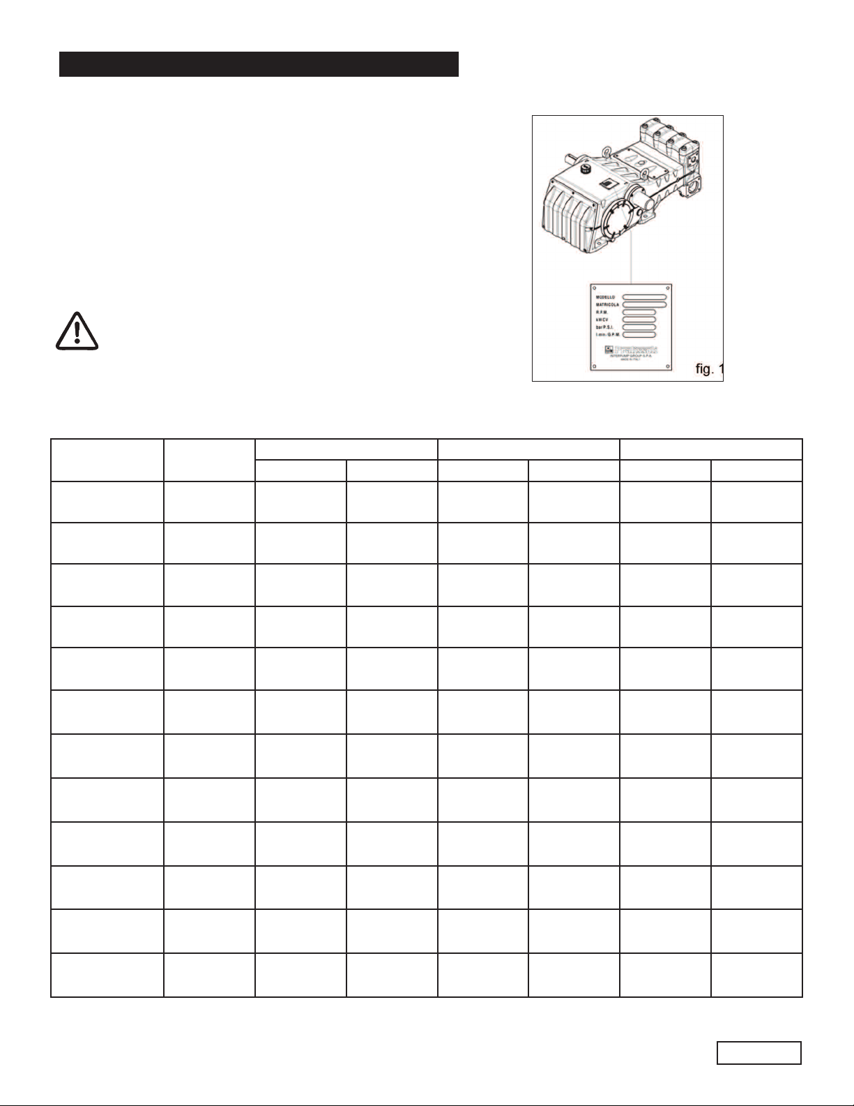
4. PUMP IDENTIFICATION
Each pump has a rating plate bearing the following information:
Pump model and version
Serial Number
Maximum RPM
Power consumption Hp-kW
Flow Rate in l/mn - GPM
Pressure in bar/PSI
Pump model, version and serial number must
always be specified when ordering
spare parts.
5. TECHNICAL FEATURES
LK SERIES
MODEL RPM
LK3615 1500 37.0 140 5800 400 145 107
LK3617 1750 40.1 152 5800 400 158 116
LK4015 1500 45.7 173 5075 350 157 115
LK4017 1750 49.6 188 5075 350 171 126
LK4515 1500 57.6 218 4060 280 159 117
LK4517 1750 62.8 238 4060 280 173 127
LK5015 1500 71.0 269 3335 230 161 118
KL5017 1750 77.6 294 3335 230 176 129
LK5515 1500 86.1 326 2755 190 161 118
FLOW RATE PRESSURE POWER
GPM l/min PSI Bar Hp kW
LK5517 1750 93.7 355 2755 190 176 129
LK6015 1500 102.4 388 2320 160 161 118
LK6017 1750 111.7 423 2320 160 176 129
Page 6
GENERAL PUMP
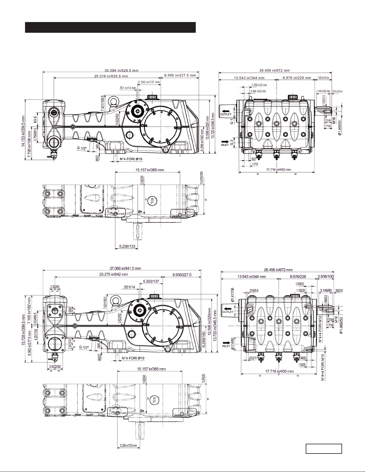
6. DIMENSIONS AND WEIGHTS
For dimensions and weight of LK36, LK40 and LK45 pumps, please refer to fig. 2.
A member of the Interpump Group
LK SERIES
Weight: 790 Lbs./358 Kg.
For dimensions and weight of LK50, LK55 and LK60 pumps, please refer to fig. 2a.
fig. 2
Weight: 829 Lbs./376 Kg.
fig. 2a
Page 7
GENERAL PUMP
A member of the Interpump Group
LK SERIES
7.INFORMATION ABOUT PUMP USE
The LK pump has been designed to operate with filtered water (see paragraph 9.6) and at
maximum temperature of 1040F (400C).
Other fluids may be used only upon the approval of The Customer Service Department .
7.1 Water Temperature
The max water temperature is 1040F (400C). However, it is possible to use the pump at temperatures of up
to 1400F (600C) for short periods of time. In this case we advise consulting the Customer Service
Department.
7.2 Max Flow Rate and Pressure Values
The performance figures given catalog refer to the maximum performance of the pump. Regardless of the power used,
pressure and maximum RPM values indicated on the plate may not be exceeded unless expressly authorized by the
Customer Service Department.
7.3 Lowest RPM
Any RPM value different from what is indicated in the performance table (see section 5) must be expressly authorized by
the Customer Service Department.
7.4
Recommended Lubricant Oil Types & Manufacturers
The pump is delivered with lubricant oil compliant with room temperatures ranging between 320and 860F (00and
300C ). Some recommended lubricant types are indicated in the table below; these lubricants are treated with additives
in order to increase corrosion protection and resistance to fatigue. As an alternative, Automotive SAE 85W-90 gearing
lubricants may also be used.
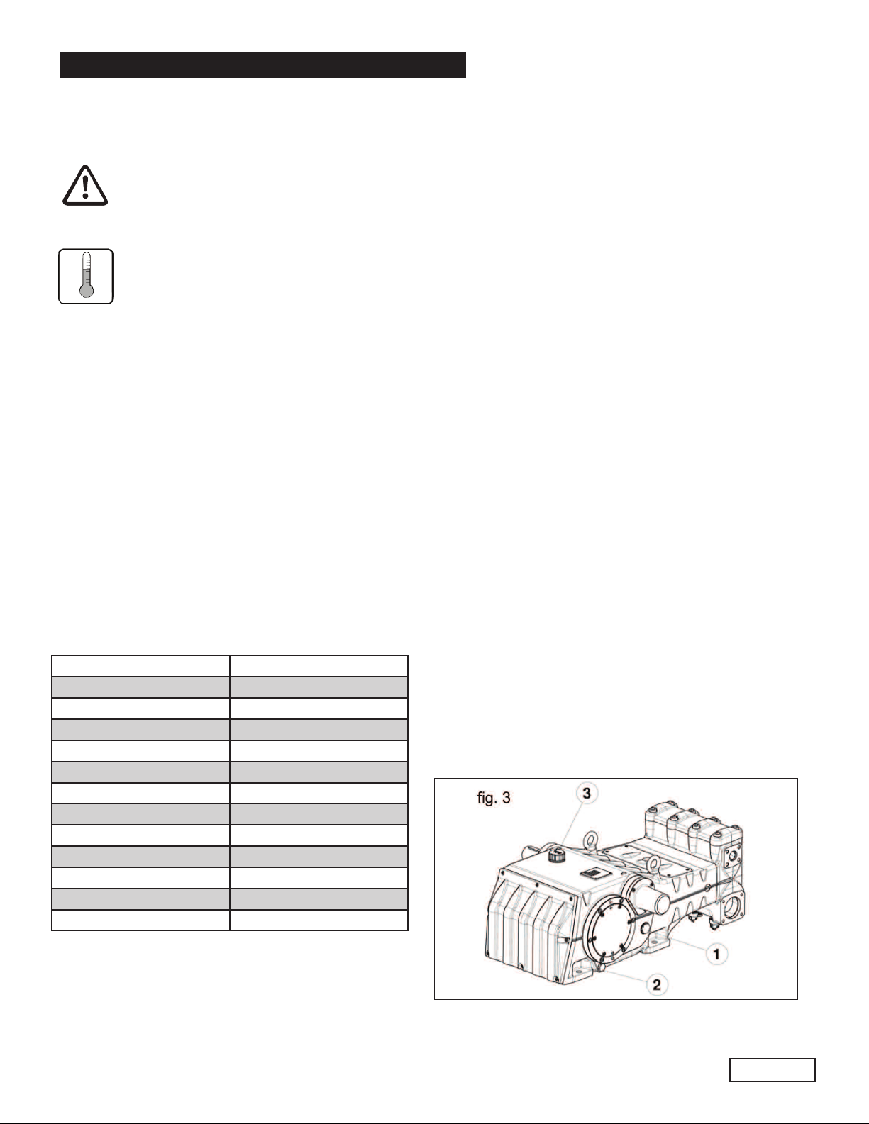
Check the oil level with the oil level lights located on the
sides pos. 1, fig. 3. If necessary, top up via the oil plug pos.
3, fig. 3. To correctly check the oil level, the pump must be
BRAND TYPE
GENERAL PUMP SERIES 220
ARAL Aral Degol BG220
BP ENERGOL HLP 220
CASTROL
ELF
ESSO NUTO 220
FINA Cirkan 220
FUCHS RENOLIN 220
MOBIL DTE OIL BB
SHELL TELLUS C 220
TEXACO RANDO HD 220
TOTAL CORTIS 220
Hyspin VG 220, Magna
POLYTELIS 220
220
at ambient (room) temperature. To change the oil the pump
must be at operating temperature, and is done by removing the plug, pos. 2, fig. 3. Checking and changing the oil
must be done as shown in section 11. The quantity
necessary is 473.3 oz. (14 liters).
Page 8
 Loading...