

General Pump KEZ Series Repair Manual
KEZ
Repair Manual
8
Ref 300666 Rev. B
03-18

GENERAL PUMP
INDEX
1. INTRODUCTION ..................................................Page 3
2. REPAIR ISTRUCTIONS ............................................Page 3
2.1 Crank Mechanism Repair. . . . . . . . . . . . . . . . . . . . . . . . . . . . . . . . . . . . . . . . . Page 3
2.1.1 Crank mechanism disassembly ........................... Page 4
2.1.2 Crank mechanism assembly .............................Page 4
2.1.3 Disassembly/Assembly of bearings and shims ...............Page 6
2.2 Fluid End Repair ...............................................Page 9
2.2.1 Disassembly of the head - valve units ...................... Page 9
2.2.2 Head assembly - valve units .............................Page 10
2.2.3 Disassembly of the head - seals ..........................Page 11
2.2.4 Plunger unit disassembly ................................ Page 13
2.2.5 Head assembly - seals - plunger unit ...................... Page 13
3. SCREW CALIBRATION ............................................Page 14
4. REPAIR TOOLS ..................................................Page 14
A member of the Interpump Group
KEZ SERIES
Ref 300666 Rev. B
03-18
Page 2
GENERAL PUMP
A member of the Interpump Group
KEZ SERIES
1. INTRODUCTION
This manual describes the instructions for repairing the KEZ Pump, and must be carefully read and understood before
performing any repair intervention on the pump.
Correct use and adequate maintenance is fundamental for the pumps regular operation and long duration. General
Pump declines any responsibility for damage caused by misuse or the non-observance of the instructions described in
this manual.
2. REPAIR INSTRUCTIONS
2.1 Crank Mechanism Repair
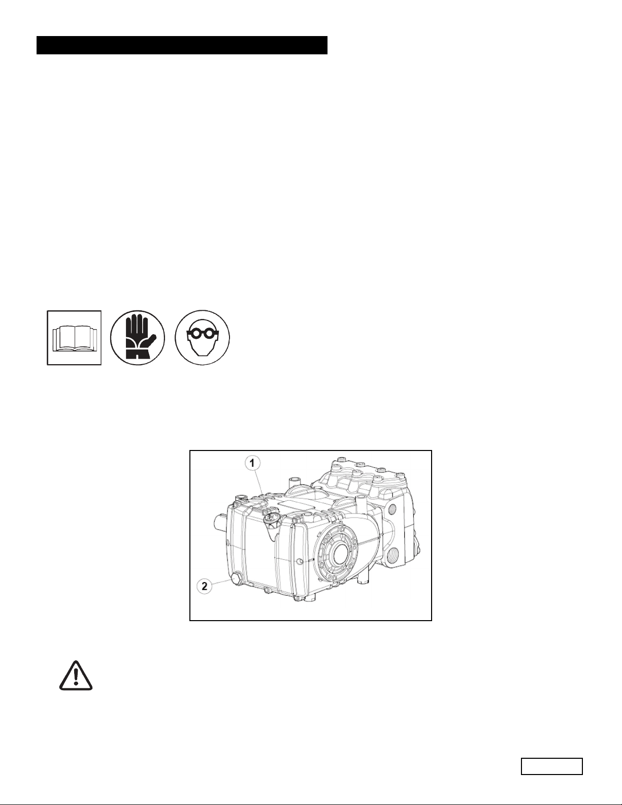
Crank mechanism repair operations must be carried out after draining the oil from the crankcase. To
drain the oil, remove the oil dipstick (1), and then the plug (2), in fig. 1.
fig. 1
Exhausted oil must be collected in an appropriate container and disposed of in appropriate
locations. In absolutely no case may it be disposed of in the environment.
Ref 300666 Rev. B
03-18
Page 3
GENERAL PUMP
2.1.1 Crank mechanism disassembly
The correct sequence is the following:
A) Dissasemble:
• pump shaft key
• rear cover
• connecting rod cap
• side covers, using 3 wholly threaded M6 x 50 screws, inserting
them in the holes as shown in fig. 2.
A member of the Interpump Group
KEZ SERIES
fig. 2
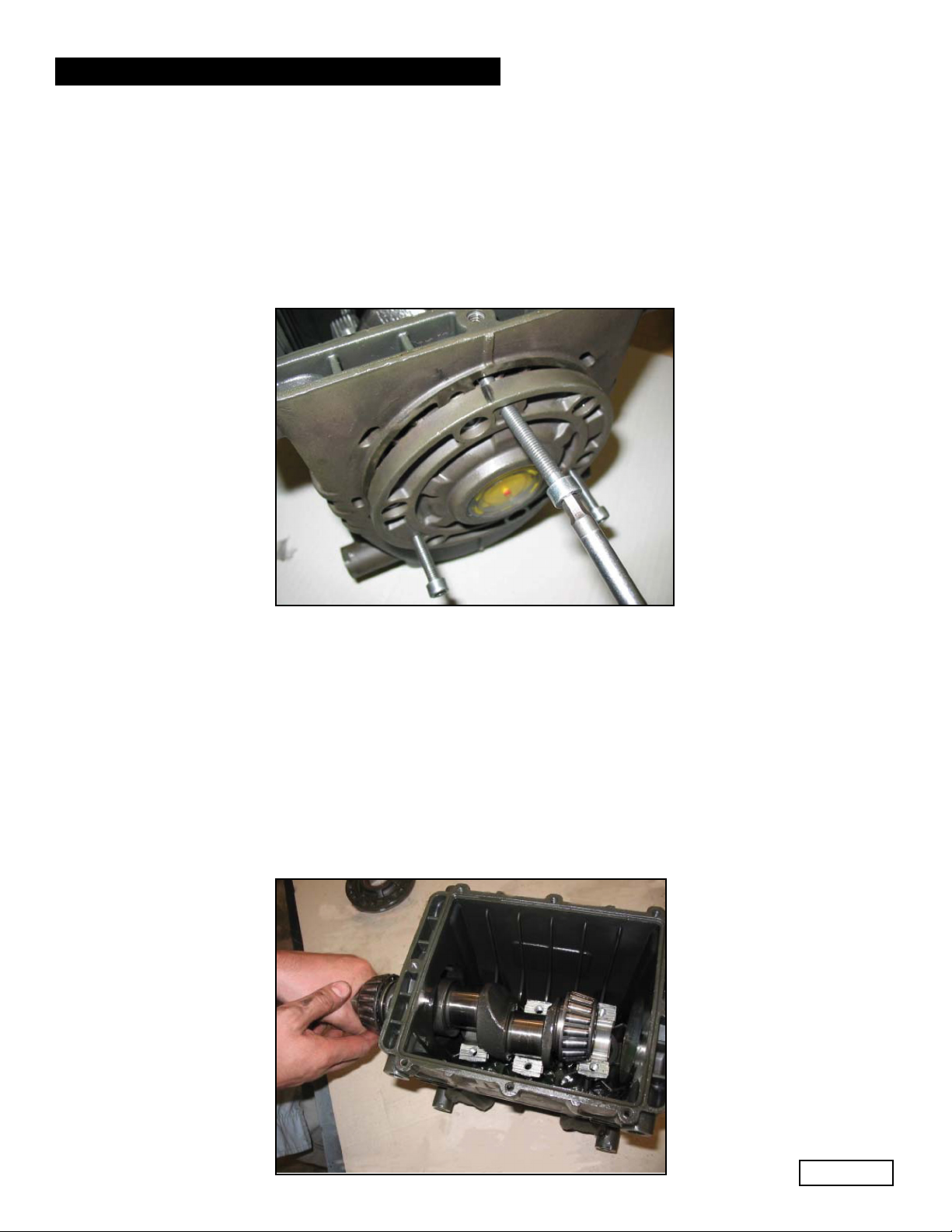
B) Push the plunger guides and connecting rods forward in order to facilitate the lateral extraction of the
crankshaft.
NOTE: to extract the plunger guide it is necessary to remove the ceramic plunger and wiper first.
C) Disassemble the crankshaft oil seals and the plunger guides using standard tools.
2.1.2 Crank mechanism assembly
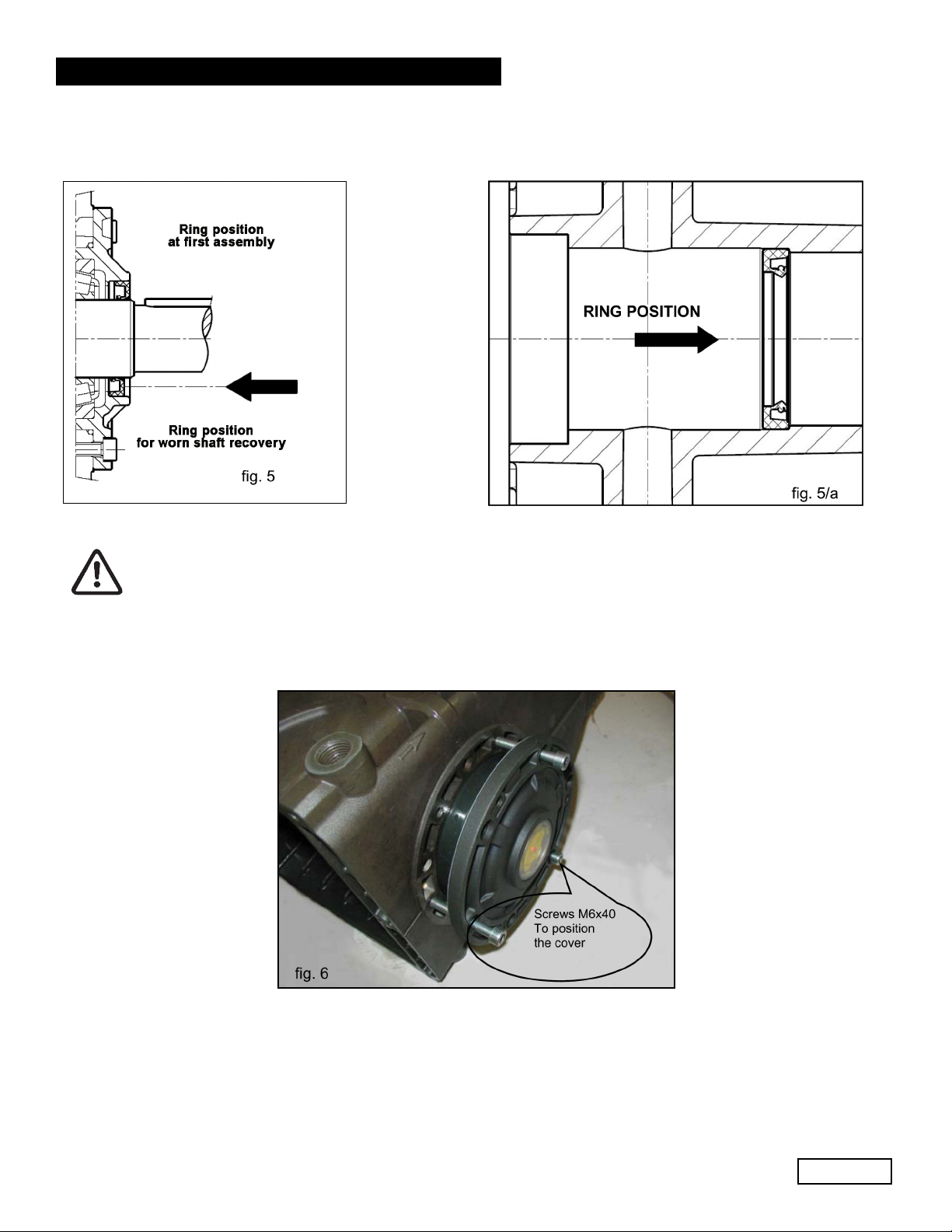
A) Fit the oil seals of guide plungers in the crankcase by sliding them all the way inside until they correctly
seat in place (see fig. 5a). The use of the tool #F27904200 will facilitate the task.
B) Introduce the pre-assembled plunger guide/connecting rod units into their seat; to facilitate tightening
of the connecting rod cap, we advise to position the connecting rod so you can easily read the number.
To easily introduce the crankshaft, without the key, fully push in the plunger guide/connecting rod unit,
as indicated in section B, paragraph 2.1.1, and shown in fig. 4.
fig. 4
Ref 300666 Rev. B
03-18
Page 4
GENERAL PUMP
B) Before reassembly of the side covers, check the seal lips for wear. If replacement is necessary, position
the new ring using the correct tool (#F27904500) as shown in fig. 5.
A member of the Interpump Group
KEZ SERIES
If the shaft presents diameter wear corresponding to the sealing lip, to avoid the need for griding it’s
possible to position the ring as indicated in fig. 5.
To help the covers fit onto the crankcase, we advise to use 3 screws, M6 x 40, and then finish the
operation with the screws supplied (M6 x 18) as shown in fig. 6.
Ref 300666 Rev. B
03-18
Page 5
 Loading...