

General Pump EP1506G8, EP1509G8, EP1508G8, EP1510G8, EP1308G8 Instructions For The Installation And Use
...Page 1
GENERAL PUMP
8
A member of the Interpump Group
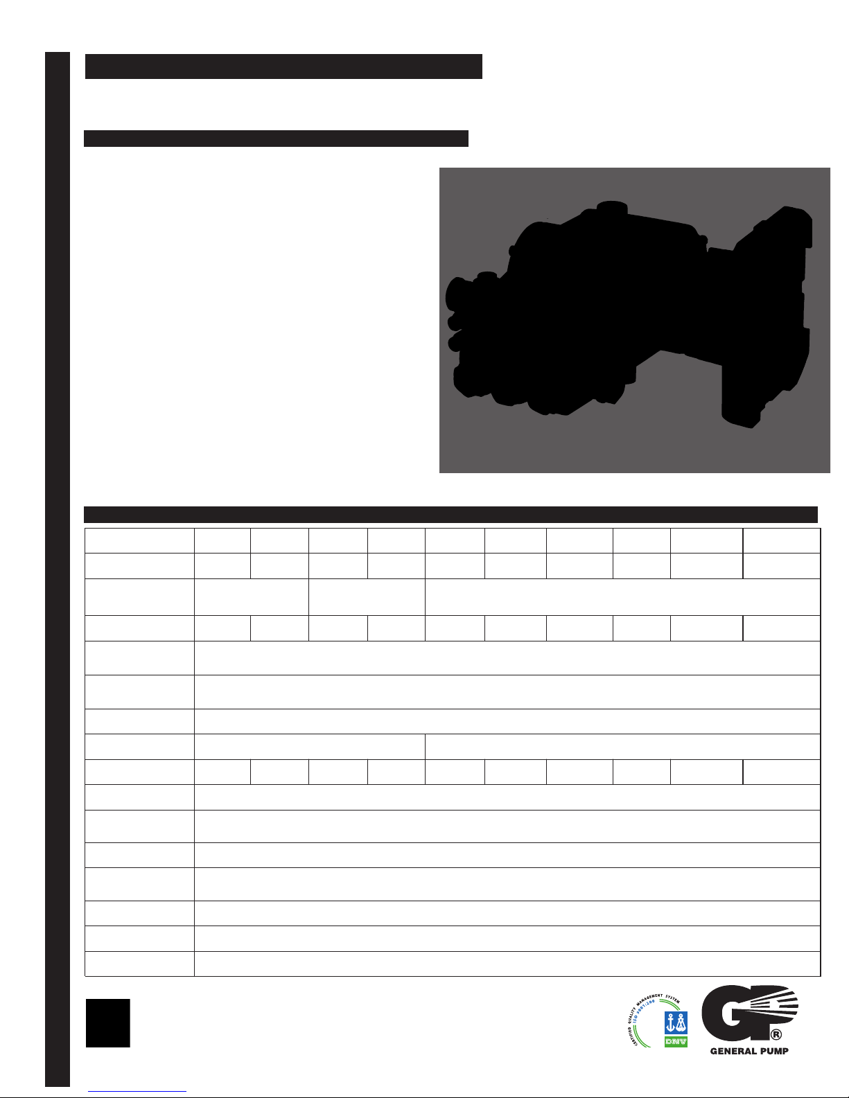
FEATURES
• Triplex plunger pump
• New Forged brass manifold , increases
working pressure to 4,000 PSI
• New plunger guide bushing
(patent pending)
• Solid ceramic plungers with dual guide
system
EMPEROR
• New dual diameter plunger guide
• New optimized outlet valves
• New dual lip oil seal
• 1” Hollow shaft, flanged for direct couple
to gas engines (SAE J609B)
EP Series
Triplex Plunger Pump, 1” Hollow Shaft
SPECIFICATIONS
Pump Model
Maximum Volume
Maximum Discharge
Pressure
Horsepower
Maximum Pump
Speed
Maximum Inlet
Pressure
Max. Inlet Vacuum
Plunger Bore
Plunger Stroke
Oil Capacity
Maximum Fluid
Temperature
Inlet Port Thread
EMPEROR
Discharge Port
Thread
Shaft Diameter
EP1506G8 EP1508G8 EP1509G8 EP1510G8 EP1306G8 EP1308G8 EP1309G8 EP1310G8
2.9 GPM 3.4 GPM 3.7 GPM 4.2 GPM 2.1 GPM 2.6 GPM 2.9 GPM 3.2 GPM
3,045 PSI 3,000 PSI 4,000
6.0 HP 7.1 HP 7.6 HP 8.7 HP 5.7 HP 7.1 HP 7.9 HP 8.6 HP
3400 RPM
125 PSI
Flooded
.591 in/15 mm .512 in./13 mm
.236 in./6 mm .315 in./8 mm .354 in./9 mm .394 in./10 mm .236 in./6 mm .315 in./8 mm .354 in./9 mm .394 in./10 mm .433 in./11 mm .512 in./13 mm
15 oz.
165oF
1/2”-14 BSP-F
3/8”-19 BSP-F
.945 in./24 mm
EP1311G8 EP1313G8
3.4 GPM 4.0 GPM
9.3 HP 10.7 HP
Weight
Dimensions
General Pump
is a member of
the Interpump Group
15.4 lbs.
9.5”x9.5”x6.45”
Ref 300922 Rev.A
02-13
Page 2

GENERAL PUMP
Instructions and Recommendations for the Installation of
A member of the Interpump Group
1” Hollow Shaft - Gas
EP Series Pumps
EP Series
Maximum temperature of the water through the pump
o
is 165
In order to obtain maximum performance in terms of
duration of seals and valves, it is necessary to respect
a few simple rules, as follows:
1) In order to avoid damage caused by cavitation,
F (85oC).
the pump must be pressure fed.
The higher the inlet pressure, the longer the life of
the wet end of the pump.
o
When working at 185
feed pressure - measured directly in the inlet port
of the pump when it is working - is 45 psi (3 bar).
The minimum feed pressure accoridng to the
different temperatures are:
F (85oC), the minimum
the pump, for example for a 4 gpm (15 l/min)
pump, put a filter from 16 to 20 gpm (60-
75 l/mi)The mesh size suitable for this
application is 0.016” (.4 mm).
c) It is extremely important to put a pressure
switch on the suction port of the pump, and in
any case downstream from the filter, so that
it can stop the pump should the feed pressure
drop by 20% due to the filter clogging or
failure of the feed pump, etc.
3) Change of oil
We recommend the first oil change after the
first 50 hours, with the pump stopped and
the oil still warm.
This change is not recommended because the oil
has lost its properties, but rather to eliminate the
impurities that have gotten into the oil during the
running-in phase. If these impurities are not
removed, but are allowed to remain in the oil, they
may cause premature wear to the moving parts
and the oil seals. After this initial change, the
oil can then be changed every three months
or 300 hours of operation thereafter.
Naturally, if the application allows for feeding the pump
with 45 psi (3 bar) even at low temperatures
(for example: 115
pump will be even longer.
2) The plumbing which feeds the pump must be
of a diameter at least equal to the inlet port.
Also, follow the suggestions below:
a) Make the plumbing as short and straight as
possible, preferably in an upward direction to
facilitate the expulsion of eventual air bubbles
naturally if compatible with the requirements
of the system.
b) It is always useful to put a filter at the inlet
with capacity of 4 to 5 times the flow of
o
F/45oC the life of the wet end of the
Ref 300922 Rev.A
02-13
Please note: If the pump works in conditions with
high humidity and with sharp temperature
changes, it is possible that condensation will
appear inside the crankcase, which mixing with
the oil can change its properties. This is easy
to see because the oil changes to a white, milky
color.
If the pump does not have excessive water
leaking from the packings, and the oil becomes
milky, the oil has to be changed more frequently.
The percentage of water in the oil must not
exceed 20%.
Use oil per the following chart:
CHART OF COMPATIBLE OILS SAE15W40
General Pump Series 100
BP VISCO 2000
CASTROL CWX
MOBIL SUPER
SHELL HELIX SUPER
TOTAL QUARTZ 4000-5000
Page 3

GENERAL PUMPA member of the Interpump Group
EP Series
1” Hollow Shaft - Gas
PARTS LIST
ITEM PART NO. DESCRIPTION QTY
1. 58120041 Manifold, Ø 13 1
58120141 Manifold, Ø 15 1
2. 36202551 Valve Cage 3
3. 94737600 Spring, Ø 9.4x14.8 3
4. 36711501 Valve 3
5. 36200366 Valve Seat 3
6. 90384100 O-ring, Ø17.13v2.62 3
7. 36711501 Valve Assembly 3
8. 701002 O-ring, Ø20.24x2.62 3
9. 98222600 Valve Cap, M24x1.5x16.7 3
10. 99169000 Plunger Bolt, M5x55 3
11. 96690500 Washer, Ø 5x11.5x0.4 3
12. 58040009 Plunger, Ø 13x42 3
58040109 Plunger, Ø 15x42 3
13. 90358900 O-ring, Ø 12.42x1.78 3
14. 36211366 Outlet Valve Seat 3
15. 36211276 Outlet Valve Poppet 3
16. 94733300 Spring, Ø 6.2x10.4 3
17. 36211151 Outlet Valve Cage Guide 3
18. 36719301 Complete Outlet Valve 3
19. 701016 O-ring, Ø 15.6x1.78 3
20. 98213700
21. 99317500 Screw, M8x60 8
22. 44100251 Head Ring, Ø 13 3
63101051 Head Ring, Ø 15 3
23. 90260200 Packing, Ø 13, HP 3
90261100 Packing, Ø 15, HP 3
Outlet Valve Cap, M18x1.5x10
3
ITEM PART NO. DESCRIPTION QTY
24. 90507650 Anti-ext. Ring, Ø 13 3
90508990 Anti-ext. Ring, Ø 15 3
25. 58605601 Intermed. Ring, Ø 13 3
58605701 Intermed. Ring, Ø 15 3
26. 701023 O-ring, 26.7x1.78 3
28. 90260100 Seal, Ø 13, LP 3
90260800 Seal, Ø 15, LP 3
29. 58210670 Support Ring, Ø 13 3
58210770 Support Ring, Ø 15 3
30. 98210000 Plug, 3/8”x13 1
31. 96738000 Gasket, 17.5x23x1.5 1
32. 98217600 Plug, 1/2” BSPx10 1
33. 96751400 Gasket, Ø 21.5x27x1.5 1
34. 96698000 Washer, Ø 7.5x15x0.5 3
35. 58210582 Gasket, Ø 3x94 1
36. 58010022 Crankcase 1
37. 58210451 Drip Cover 1
38. 90156550 Oil Seal, Ø 15x24x5.7 3
39. 58050066 Piston Guide 3
40. 97734000 Piston Pin, Ø 10x29.5 3
41. 58030022 Connecting Rod 3
44. 44211801 Sight Glass 1
47. 90409700 O-ring, Ø 55.56x3.53 1
50. 98210500 Oil Dipstick 1
52. 58160022 Rear Cover 1
53. 98204100 Plug, 1/4”x9 1
54. 701013 O-ring, Ø 10.82x1.78 1
Ref 300922 Rev.A
02-13
ITEM PART NO. DESCRIPTION QTY
51. 90392550 O-ring, Ø 113.97x2.62 1
55. 98196600 Plug, 1/8”x8 1
56. 99303700 Screw, Hex Head 4
57. 96701600 Washer, Ø 8.4 4
58. 50200074 Pump Foot 2
72. 90063500 Circlip, Ø 25 1
73. 63027765 Crankshaft, 6.5 mm 1
(EP1506G8, EP1306G8)
63028065 Crankshaft, 8 mm 1
(EP1508G8, EP1308G8)
63028265 Crankshaft, 9 mm 1
(EP1309G8, EP1509G8)
63028465 Crankshaft,10 mm 1
(EP1510G8, EP1310G8)
63029265 Crankshaft, 11 mm 1
(EP1311G8)
63029065 Crankshaft, 13 mm 1
(EP1313G8)
74. 99179000 Set Screw, M6x6 1
75. 91856800 Needle Bearing 1
76. 90409700 O-ring 1
77. 10051822 Flange 1
78. 90168700 Oil Seal, Ø 45x60x8 1
79. 99275500 Screw, Hex Head 4
80. 203476 Washer, Ø 8.4x15x1.5 4
81. 99191200 Screw, M6x30 4
82. 203510 Washer, Ø 6.4x10x.7 4
Page 4

GENERAL PUMP
A member of the Interpump Group
EP Series
1” Hollow Shaft - Gas
REPAIR KITS
KIT NO. K269 K270 K271
ITEM NO’S
INCLUDED
IN KIT
NUMBER OF
ASSY’S
IN KIT
NO. OF
CYLINDERS
KIT SER
VICES
2, 3, 4, 5,
6, 13, 14,
15, 16, 17,
(7), (18)
6 6 3 3 1 3 1
3 3 3 3 1 3 1
DIMENSIONS
8, 9,
19, 20
TORQUE SPECS*
Position Ft.-Lbs. Nm.
9 96 130
Ø 13 Ø 15
K272 K275 K273 K276
22, 23, 24,
38
26, 28
22, 23, 24,
25, 26, 28
29
22, 23, 24,
26, 28
22, 23, 24,
25, 26, 28
29
*Decrease torque by 20% if threads are lubricat
10 4.5 6
20 26 35
21 14.8 20
30 30 40
32 30 40
43 7.4 10
53 14.8 20
55 9.6 13
56 14.8 20
81 7.4 10
ed.
**Use Loctite 542 Red
GENERAL PUMP
1174 Northland Drive Mendota Heights, MN 55120
Phone: 651.686.2199 FAX: 800.535.1745 e-mail: sales@gpcompanies.com www.generalpump.com
Ref 300922 Rev.A
02-13
 Loading...