

Page 1
JM-3080™ Gas Jet
Operating Instructions
Your JM-3080 Jet-Set gas-powered
water jet is designed to give you years of
trouble-free, profitable service. However,
no machine is better than its operator.
Read, understand and follow all safety
warnings and instructions provided with
the product. Failure to follow the warnings
and instructions may result in electric
shock and/or serious injury. Save all warnings and instructions for future reference.
SAVE THESE INSTRUCTIONS!
Page 2
Jet-Set JM-3080™
WARNING! Read and understand all instructions.
Failure to follow all instructions listed below may result in
electric shock, fire and/or serious personal injury.
Replacement manuals are available upon request at no
charge, or may be downloaded from our website,
www.drainbrain.com. Instructional videos are available
for download on our website, and may be ordered. If you
have any questions or problems, please call General’s
customer service department at 412-771-6300.
SAVE THESE INSTRUCTIONS!
These instructions are intended to
familiarize all personnel with the safe operation
and maintenance procedures for the JM-3080.
Serious injury or death may occur
from inhaling engine exhaust or dangerous vapors. Use this product only
in a well ventilated area. This water jet
is designed for outdoor use only. Always
make sure there is adequate ventilation
(fresh outside air) for breathing and combustion.
Do not operate power tools in explosive atmospheres, such as in the
presence of flammable liquids, gases,
or dust. Power tools create sparks which
may ignite the dust of fumes.
Do not spray flammable liquids. Risk
of explosion. Flammable liquids can create fumes which can ignite causing property damage or severe injury.
SAFETY SYMBOLS
This is the safety alert symbol. It is used
to alert you to potential personal injury
DANGER indicates a hazard with a high level of risk which, if not
avoided, will result in death or serious injury.
WARNING indicates a hazard with a medium level of risk which, if
not avoided, could result in death or serious injury.
hazards. Obey all safety messages that
follow this symbol to avoid possible
injury or death.
Do not direct discharge stream at people. This equipment can produce a high
pressure stream of fluid that can pierce
skin and its underlying tissues, leading to
serious injury and possible amputation or
death.
Always wear safety glasses and rubber soled, non-slip shoes. High pres-
sure spray can cause paint chips or
other particles to become airborne
and fly at high speeds. Use of this
safety equipment may prevent serious
injury.
WARNING
This product contains lead, a chemical known to the State of
California to cause birth defects or other reproductive harm.
Wash your hands after handling this product.
CAUTION indicates a hazard with a low level of risk which, if not
avoided, will result in minor or moderate injury.
WARNING
This product contains one or more chemicals known to the State
of California to cause cancer and birth defects or other reproductive harm.
2
Page 3
Jet-Set JM-3080™
GENERAL SAFETY RULES
WARNING
Read and understand all instructions. Failure to follow all instructions listed below may result in electric shock, fire, and/or
serious injury.
SAVE THESE INSTRUCTIONS!
WORK AREA SAFETY
1. All installations must comply with local codes. Contact your
plumber, utility company or the selling distributor for specific details.
2. Risk of explosion. Do not spray flammable liquids or operate
in an area where flammable or explosive materials are used
or stored. Power tools create sparks which may ignite dust and
fumes.
3. Keep bystanders, children, and visitors away while operating
machine. Distractions can cause you to lose control.
PERSONAL SAFETY
1. High pressure developed by jet machines will cause personal
injury. Water spray should not be pointed at any person. High
pressure spray can result in serious injury. If fluid seems to have
penetrated the skin, seek emergency medical attention at once.
2. Grip jet hose or spray wand securely with both hands before
starting the machine. Failure to do so could result in injury from a
whipping hose or wand.
3. Always wear eye protection and rubber gloves. Safety equipment, eye safety devices, non-skid safety shoes and protective
clothing must be worn when using this equipment.
4. Do not touch engine during operation. The muffler and other
parts of the engine get hot and can cause severe burns.
5. Do not smoke while filling engine fuel tank. Fumes can ignite
causing property damage and severe injury.
6. Stay alert, watch what you are doing and use common sense
when operating a power tool. Do not use tool while tired or
under the influence of drugs, alcohol, or medication. A mo-
ment of inattention while operating power tools may result in serious personal injury.
7. Dress properly. Do not wear loose clothing or jewelry. Con-
tain long hair. Keep your hair, clothing, and gloves away from
moving parts. Loose clothes, jewelry, or long hair can be caught
in moving parts.
SERVICE
1. Tool service must only be performed by qualified service
personnel. Service or maintenance performed by untrained per-
sonnel could result in injury and damage to the equipment.
2. When servicing tool, use only identical replacement parts.
Follow instructions in maintenance section of this manual.
Use of unauthorized parts or failure to follow maintenance instructions may cause injury or damage to equipment.
JET SAFETY
1. Do not operate jet above rated pressure or above 140 degrees
(rated water temperature). Operating jet above rate specifica-
tions risks damage to the pump and related components, and will
void the warranty.
2. Do not operate jet with the output valve in the off position for
extensive periods of time. This will cause the water to overheat
and damage the pump.
3. Never run pump without water in it. Operating the machine
without water will cause the pump to fail and void the warranty.
4. Check for worn hose and components before each use.
Check that all fittings are secured before using jet. Worn or
lose fittings can cause damage to the machine and injure the operator.
5. Protect machine and pump from freezing. Storing or operating
the jet in temperatures below freezing can damage pump, hose
and other jet components. Store unit indoors or protect with antifreeze when not in use.
6. General Wire Spring Co. will not be liable for any changes
made to our standard machines or any components not purchased from General Wire Spring Co.
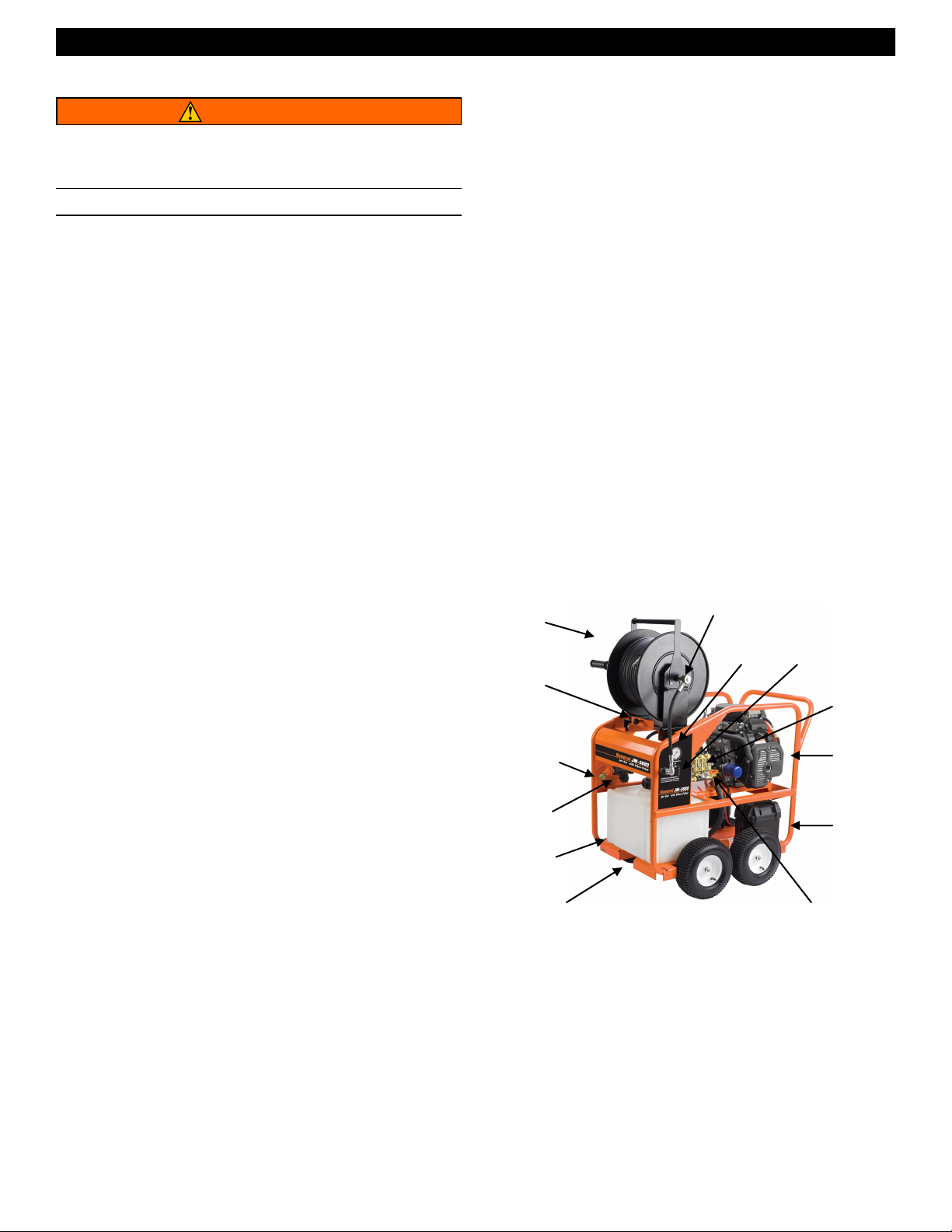
JM-3080 SPECIFICATIONS
250 ft. Hose Reel
Hose Reel
Release
Knob
Water Inlet
Inlet Filter
12 Gallon
Buffer Tank
Buffer Tank Outlet Valve
Buffer Tank
The J-3080 is equipped with a 12 gallon buffer tank. If the incoming
water flow is less than 8 gpm required by the pump, the buffer tank
will protect the pump from cavatation and damage. For instance, if
your water supply can only provide 6 gpm, you can still run the jet for
8 minutes before stopping to let the holding tank refill.
Removable Hose Reel
This Jet features a removable hose reel. It easily detaches in seconds for remote operation. To remove reel, unscrew twist connect at
the control panel outlet, then simply pull the knob at the base of the
reel, and lift the reel. To reattach reel, align the base of the reel in the
carriage, then allow the knob to snap back into place.
3
Swivel
Pressure
Gauge
Output Valve
Pump
Engine
Battery Box
Pulse Valve
Page 4
Jet-Set JM-3080™
JET HOSE
1. When selecting hose size, consider that pressure is lost as the
water travels down the length of the hose. As the length increases,
the pressure decreases. In addition, the smaller the diameter of
the hose, the greater the loss of pressure per foot will be. As an
example, at 4 GPM, a 3/8” hose will lose 90 lbs. of pressure over a
100 ft. length. The gauge reflects pressure from the pump only,
not pressure at the end of the hose. It is important to select the
largest possible hose size in order to have as much pressure as
possible at the end of the hose.
2. Hoses of the same diameter may be coupled together using the
CC-1 coupling, but it is not recommended for use in lines smaller
than 8” in diameter. The long length of the hose connectors and
coupling together can get caught in bends in the line. It is not advisable to have two different hose sizes coupled in a drain line.
There is a tremendous loss of pressure when combined, aside
from the difficulty of getting around bends.
HOSE SELECTION GUIDE
Hose Size
(ID*)
3/8” 4” - 8” Floor drains, septic
1/4” 2” - 4” Kitchen sinks, laundry
* Inside Diameter
Pipe Size Typical Applications Available Hose
Lengths
100 ft., 200 ft.,
lines, long runs
drains, clean outs
250 ft., 300 ft.
100 ft., 150 ft.,
200 ft.
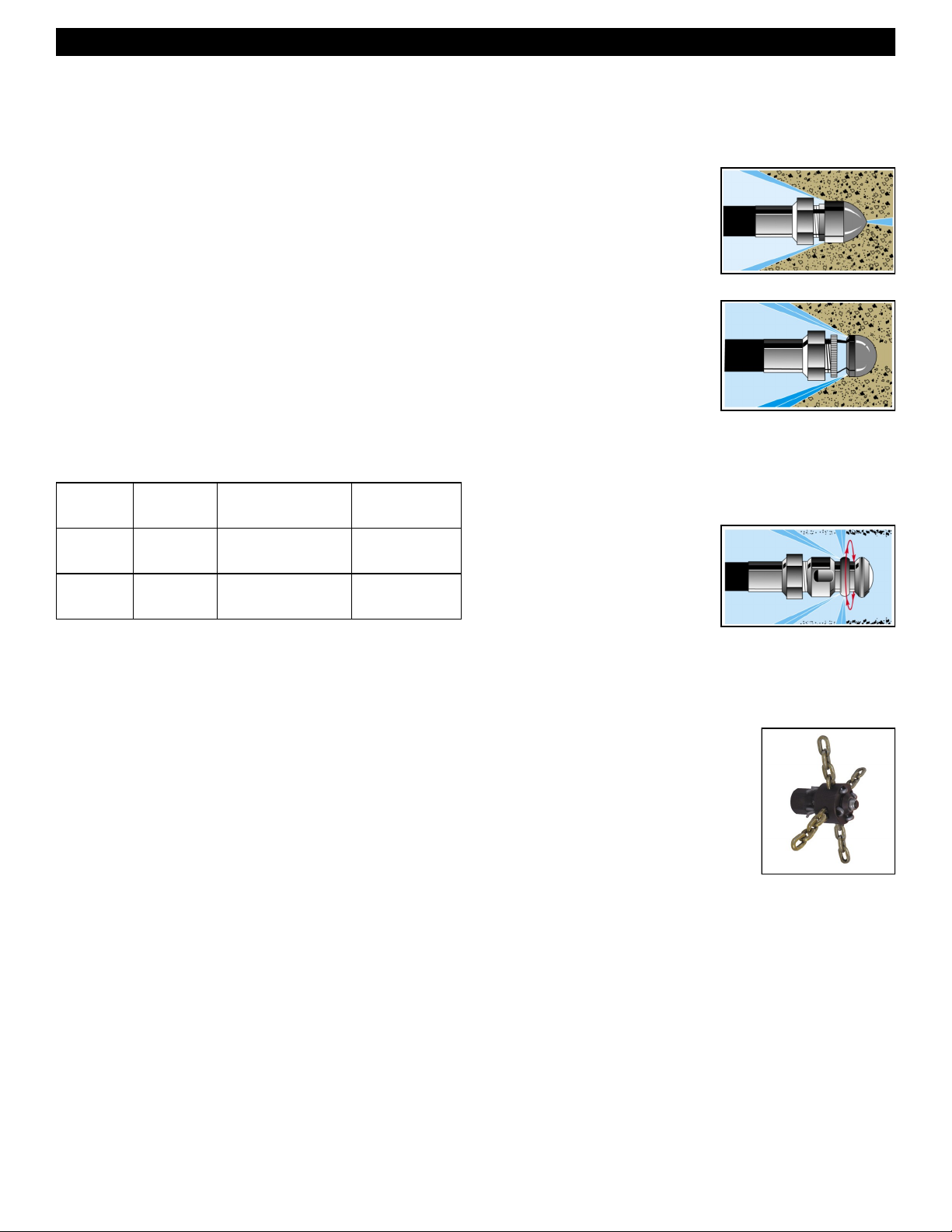
4. Use the nozzle selection guide to determine what nozzle you will
need for various applications. Examples: If a nozzle is stamped
#111, it is a JN-111, drilled for 8 GPM @ 3000 PSI with several
15° rear jets and one forward cutting jet.
Powerful penetrating nozzle cuts
through grease and ice.
Wide spray flushing nozzle cleans
inside of pipe thoroughly.
ROTARY NOZZLES
Rotary nozzles are useful as a finishing
tool. After the line has been cleared,
you may switch to the rotary nozzle to
more thoroughly clean the walls of the
pipe. Use these nozzles only in a predominantly straight run since they are
longer than regular nozzles and may
get caught in tight bends.
JET NOZZLES
1. A variety of jet nozzles are available for drain cleaning. Each has a
different spray pattern and purpose. Some nozzles may have an
orifice in the front to cut through the stoppage. All will have holes
in the back to drive the hose down the line and clean the walls of
the pipe. A tight spray pattern (15°) has more driving power for
long runs, a wide spray pattern (40°) does a better job of cutting
the grease off of the walls of the pipe. A combination of nozzles
may be required to clear a line. Always turn off the machine and
turn off output valve before changing nozzles.
2. Make sure the nozzle you are using matches the pump size. A
3000 psi pump requires a different nozzle orifice than a 1500 psi
pump. Mismatching nozzles with pump size will either cause too
little pressure, which may not clear the drain, or too much pressure, which may damage the machine.
3. Check nozzles before and after each use for clogged holes which
can cause pressure to increase to dangerously high levels and
damage the pump. A clogged hole can be cleared by simply using
the NCT Nozzle Cleaning Tool.
CHAIN SAW NOZZLES
Chain saw nozzles spin at up to 10,000 rpm to
rip through roots. Lengths of chain can be
quickly and easily switched for different diameter pipes.
4
Page 5
Jet-Set JM-3080™
NOZZLE SELECTION GUIDE
HOSE SIZE 1/4” 3/8”
CAT # CAT #
Thruster Nozzle JN-101 JN-111
Flusher Nozzle JN-102 JN-112
High Thrust Degreaser Nozzle JN-103 JN-113
Monster Nozzle JN-104 JN-114
Rotary Nozzle (Optional) JNRB-7 JNRB-11
Chain Saw Nozzle (Optional) - JCSN-11
JET ASSEMBLY
Upon arrival, inspect the shipping crate for damages. Uncrate and
examine all parts. Note any damage to machine or components
for claims against freight carrier.
Jet must be stored and operated in horizontal position. Never
store in upright position or oil may leak from pump. If low, fill with
SAE 30 weight non-detergent oil.
Gas jets are shipped with oil in the engine. Consult motor manu-
facturer’s guide for correct weight and amount.
Jet machines are meant to be used at or near the working area
and under operator supervision. If machine must be located out of
sight of operator, special controls may be required for proper machine operation and operator safety
OPERATION
SET-UP
1. Locate the jet near the drain line on a level surface with drainage.
Tip: Ideally, the drain line should be cleared from the downstream
side, that is, from the street back toward the house. If you must
clear the line from the drain toward the street, you may need to
use a siphon pump to clear away excess water.
2. Check the oil level in the pump. If low, fill with SAE 30 weight nondetergent oil.
3. Check the oil level in the engine. If low, fill with oil weight rec-
ommended in the motor manufacturer’s manual.
4. Check the inlet filter to make sure it’s clean before each use. To
clean, unscrew filter cap, remove the screen and rinse thoroughly
with water. Then, replace screen.
5. Check that incoming water supply is clean and free of debris.
Turn the water source on for at least 15 seconds to remove any
possible debris in the water before connecting hose to water inlet.
6. Connect one end of a water supply hose (not included) to the
water supply and the other end to the water inlet of the jet machine. Water supply must be a minimum of 20 psi and not to
exceed 100 psi. Caution: Water temperature must not exceed
140 degrees or damage to the pump can occur. Use only heavy
duty 3/4” hose of no more than 50 ft. in length. If run without an
adequate water supply, the pump will cavitate. Cavitation causes
the pump to vibrate, causing damage to the pump. Note: Lack of
water supply can lead to seal damage, causing a loss of pressure and will void the warranty to the pump.
7. Maximum temperature from the water source should not exceed
140°F (60°C). Using water hotter than 140°F (60°C) can cause
damage to the pump and void the warranty. If jet is being used to
clear ice blockages, see instructions on Ice Blockages.
8. Select the proper hose diameter for the line to be cleaned. When
using new hose, run water through it to clean it out before attaching the nozzle.
OPERATION
NEVER POINT THE END OF THE JET HOSE AT A
PERSON WHILE OPERATING.
1. Select the correct jet hose size to match the line size you are
clearing. (See Hose Section Guide) Check all hoses for wear and
damage. Tighten all connections securely.
2. Select the correct nozzle and attach to the end of the hose. (See
Nozzle Selection Guide) Note: If you are using a new jet hose, run
water through it to flush out debris before connecting a nozzle.
3. Insert the jet hose 2 to 3 feet into the drain line before turning on
machine.
4. Turn on the water supply valve fully to allow for maximum flow.
5. Turn on the jet output valve and allow water to run through the
supply hose, jet, and jet hose to purge air from system before
turning on the machine.
6. Make sure that the output valve is turned on and the water is flow-
ing.
7. Start the engine using the Engine Start-up procedures listed be-
low.
GAS ENGINE START-UP
1. Make sure that the ball valve is turned on and water is flowing.
2. Move choke lever to the closed position. Note: Do not use choke
if engine is warm or ambient air temperature is high.
3. Move throttle lever to the midpoint position.
4. Turn the engine switch to the ON position.
5. Turn the key to start the engine.
6. As the engine warms up, gradually move the choke lever to the
open position.
7. Position the throttle to the desired engine speed.
5
Page 6

Jet-Set JM-3080™
OPERATION CONTINUED
8. Guide the jet hose into the drain line. Do not feed the hose continuously, but rather, move the hose forward and back to allow the
pressure to break up the stoppage and the water flow to flush it
away. If you are clearing the line from the upstream side, this may
take more time. Clearing the line from the downstream side allows
debris to flow away easily.
9. It is often helpful to turn on the Vibra-pulse valve. The vibration
generated helps to hose overcome the friction in the line and glide
farther down the line. See Vibra-pulse section.
10. When the jet hose encounters a bend in the line, its advance may
slow or stop. The hose has a slight curve to it from the hose reel.
It may be necessary to manually feed or rotate the jet hose to work
it around the bends. If the hose won’t advance, put the hose in a
loop and rotate it a quarter to half turn so the curve of the hose
matches the pipe. It may also be necessary to pull the hose back
six inches and snap it forward to hop across a gap in the pipe
fitting.
11. Once you reach the stoppage, move the hose back and forth
through the section several times to ensure the line is thoroughly
cleared. You may also switch nozzles to a wide spray or rotary
(optional) nozzle for wall to wall cleaning action.
SPECIAL APPLICATIONS
ICE BLOCKAGES
High pressure water can be used to clear an ice blockage. A 3000 psi
gas jet can clear a 4” line at an approximate rate of one foot per min-
ute. The smaller, electric jet will take twice as long. Ambient air temperature will effect these times. Use a 15° nozzle with a forward jet.
DO NOT allow the incoming water supply to exceed 140°F (60°C) or
it could cause damage to the pump. Remember to follow the cold
weather precautions found in the Freeze Protection section.
FREEZE PROTECTION
To protect your machine from severe damage caused by water freezing inside the components, it is important to winterize it whenever it is
subjected to freezing temperatures.
The best way to protect the system is to keep it out of the cold. Barring that, the next best way is to flush the system with anti-freeze. To
do so, simply attach a short garden hose (not to exceed four feet) to
inlet on the pump and put other end into the anti-freeze container. Be
sure to remove the nozzle from the hose. Turn the machine on to
draw anti-freeze into the system. When anti-freeze flows out of the
end of the hose, turn the machine off. Connect high pressure hose
and trigger, and follow above procedure. Cycle trigger on/off so that
the anti-freeze will flow into unloader and injector section of machine.
VIBRA-PULSE®
Pulsation makes the hose
vibrate, helping the jet go
longer distances and around
tight bends easier. The pulse
control valve is located on the
front of the pump. Simply turn
the valve on to engage the
pulse. Vibra-pulse is most
effective in a 1/8” hose. You’ll
notice less vibration with a
1/4” hose, and almost none with a 3/8” hose. However, the pulse is
still effective, causing the water to burst from the nozzle hundreds of
times per second. If you are still having difficulty getting hose around
a tight bend, switch to a smaller diameter hose. Turn the pulse off
before turning machine off.
SHUT DOWN INSTRUCTIONS
After drain cleaning or spray washing is completed, run clear water
through the system. Always leave the output valve in the on position
when turning off motor. Turn off water supply and drain as much water
from the pump as possible. Remove water supply hose from inlet. If
you are in a cold climate, see Freeze Protection section.
When preparing to operate equipment for the next job, remove the
anti-freeze. To do so, reconnect water source, turn pump on and
direct flow of anti-freeze back into container. Be careful not to dilute
anti-freeze with incoming water supply. Anti-freeze, if kept relatively
undiluted, can be used again and again.
Hoses can also be protected from freezing by using compressed air to
clear them of residual water. Remember to remove nozzle from jet
hose and hold trigger of spray wand in open position.
ADJUSTING PRESSURE UNLOADER
The machine is equipped with a regulating pressure unloader to prevent pressure overload in the event that the nozzle is clogged or the
output valve or spray wand trigger is off. When the machine is in the
bypass mode, the pump will continue to run. However, running in
bypass mode for extended periods will cause damage to the pump no more than 5 minutes. Excessive temperatures will damage the
pump and void the warranty.
The machine also comes with thermal overload protection. When
water temperature in the pump increases to 140°F (60°C), the thermal relief valve will release hot water and allow cool water to enter
pump from the fresh water supply.
To adjust the unloader, loosen the lock nut and turn the knob counterclockwise to decrease pressure and clockwise to increase pressure.
Caution: Do not over-tighten unloader. Tighten lock nut after adjustments are made.
6
Page 7

Jet-Set JM-3080™
ACCESSORIES
HANDY-REEL WITH FOOT PEDAL
- Cat # HM-200-W (OPTIONAL)
The Handy-Reel allows for remove application of the jet. The jet can be positioned at
ground level, while the Handy-Reel can be
carried up on a roof to clear vents and
stacks. With the help of the Handy-Reel,
gas jets can be used for indoor applications
while the machine operates safely outside.
The Foot Pedal interrupts the flow of water between the pump and the
nozzle while leaving both hands free to guide the hose. Position the
Handy-Reel at the drain site. Connect the jet machine to the inlet on
the Foot Pedal. Select and attach nozzle to the hose on the reel. Put
the hose 2 to 3 ft. into the drain line. Follow the start-up procedures.
FOOT PEDAL ONLY - Cat # FM-1 (OPTIONAL)
The Foot Pedal can be used with any jet manufactured by General. It
interrupts the flow of water between the pump and the nozzle while
leaving both hands free to guide the hose. The pump will continue to
run in by-pass mode. Do not leave pump in by-pass for more than a
few minutes or the pump can be damaged. (See Pressure Unloader)
The Foot Pedal may be connected either at the machine or remotely
at the drain site. To use the foot pedal at the machine, remove the
hose going to the swivel on the hose reel and attach it to the inlet side
of the Foot Pedal. Then, connect the accessory hose (available in 6
ft., 25 ft., or 50 ft. lengths) between the outlet of the pedal and the
swivel on the hose reel. Some jet models may need the added length
of the accessory hose on the inlet side of the pedal.
For remote operation, pull the hose from the hose reel to the drain
site. Attach the hose to the inlet of the pedal. The pedal is designed
for 3/8” hose fittings. If using a 1/4” hose, use the AD-1 adapter, as
well. Then, attach the smaller hose (1/8” or 1/4”) to the outlet side of
the pedal. Use the smaller hose to clear the drain line.
SPRAY WAND Cat # SWA-3080
The Spray Wand can be used to clean your truck or other applications. Caution: Never clean the machine with its own spray. Follow
the same procedures listed previously for safety, set-up, operation,
and maintenance. To operate the spray wand with your water jet,
disconnect to twist connect at the output valve. Then, connect the
spray wand hose, trigger and wand at the output valve. Turn on the
water supply, then squeeze the trigger to purge air from the system.
Continue to squeeze trigger as you turn on the machine.
Hold the high pressure spray nozzle approximately 6 – 8 ft. from the
surface to be cleaned. When cleaning with a detergent, apply from
bottom up with an even left to right movement. Rinse from top down
with a similar motion. This will help reduce potential streaking. Always
apply soap to a dry surface. This will enhance penetration and detergent cling and reduce dilution of detergent with an already wet surface.
You may draw soap through the spray wand in conjunction with the
optional chemical injector. First set up the Chemical injector system
(see Chemical Injector). Then, simply turn the nozzle barrel on the
end of the wand counter-clockwise. As the spray pattern widens, more
of the detergent will be drawn through the wand. Turn the nozzle
clockwise to reduce the detergent flow and narrow the water spray
pattern to return to high pressure.
CHEMICAL INJECTOR – Cat # CMA-1
To use the chemical injector, disconnect the Twist Connect at the
output valve on the jet. Then thread the Chemical Injector on to it. The
Spray Wand then threads onto the free end of the Chemical Injector.
Do not attach Chemical Injector to the inlet side of the pump. Detergents can damage pump.
To use the detergent injector, attach one end of the siphon hose to
the barbed fitting on the injector and put the filter end into the detergent solution. Be sure the end of the hose is at the bottom of the container or bucket. Some models have adjustable valves to control the
amount of detergent drawn through the hose.
MAINTENANCE
Regular inspection is the key to preventing breakdowns and prolonging the life of the equipment. Follow this simple procedure religiously.
USE CAUTION WHEN PRESSURE WASHING. WEAR
GOGGLES AND RUBBER GLOVES AND BOOTS.
ANALYZE ANGLE OF SPRAY AND ANTICIPATE
ANGLE OF BACK SPLASH. DO NOT POINT SPRAY
AT ANYONE, INCLUDING YOURSELF. DO NOT PUT
YOUR HAND IN FRONT OF WATER SPRAY. IT CAN
PENETRATE THE SKIN AND CAUSE A NEED FOR
AMPUTATION. IT IS BEST TO START AT A 45°
ANGLE AT A 7 TO 10 FT. (2 TO 3M) DISTANCE FROM
OBJECT TO BE CLEANED. DIRECT SPRAY AT
CLOSE RANGE CAN BE POWERFUL ENOUGH TO
CAUSE DAMAGE.
DAILY
Check INLET FILTER for debris before each use.
Check that the PUMP OIL LEVEL is within operating range on
dipstick or sight glass.
Check that the jet nozzles are not clogged or worn out.
WEEKLY
Check the pressure hose for wear and damage. Damaged hose
can be repaired at a local service dealer of by your equipment
dealer.
Pump Crankcase Oil Change: Service after the 1st month, or after
20 hours. Then service every year or 500 hours. Use SAE 30W NonDetergent Motor Oil to full mark on dipstick or to dot on sight glass.
Engine Maintenance: Check engine manual for specific maintenance
procedures.
7
Page 8

Jet-Set JM-3080™
TROUBLE SHOOTING GUIDE
Problem Probable Cause Solution
Low pressure. Worn, clogged, or oversized nozzle. Clean or replace worn nozzle. Check nozzle size.
Clogged water inlet strainer. Clean or replace strainers.
Rough operation with loss of
pressure.
Water leakage at intake
manifold or crankcase.
Inadequate water supply.
Make certain water supply valve is on fully. Make certain water
supply hose is at least 3/4” in diameter, in good condition, with
no kinks or damage, and is not longer than 50 ft.
Worn or damaged piston cups. Replace piston cups.
Worn or damaged inlet or discharge valve. Replace worn valve poppets or valve springs.
Dirt or foreign particles in valve assembly. Remove any dirt particles.
Air leak in inlet plumbing. Locate air leak. Re-seal connection or replace damaged port.
Restricted inlet plumbing or air leak in inlet
plumbing.
Damaged piston, cup or pump valve.
Repair clogged inlet fittings. Check supply hose and ensure
adequate water supply.
Replace any damaged pump parts and clean out any foreign
particles.
Clogged nozzle. Clean or replace nozzle.
Worn manifold seals, piston or o-rings, or
condensation inside crankcase.
Inadequate water supply to pump, creating a
Replace seals, sleeves or o-rings. Change oil at regular intervals.
Ensure adequate tap water supply. Clear inlet filter.
vacuum lock.
Oil leaks.
Worn pistons and/or leaking crank seals,
Replace seals, sleeves or o-rings.
crankcase cover seal, or drain plugs.
Excessive wear. Worn or loose bearings.
Replace bearings. Check bearing seals, spacers and retainers.
Replace any worn parts.
Short piston cup life.
Scored cylinders from pumping acids.
Replace cylinders. Do no pump acid solutions. For acid application, ask your dealer for a pump saver injector.
Abrasive particles in fluid being pumped.
Replace water and detergent strainers if damaged or missing.
Install additional filter if fine abrasives are still evident.
Operator(s) running pump without water
Do no allow washer to be run without proper water supply.
supply.
Hot water in pump.
Do not run in bypass for more than 5 minutes. Do not let water
supply exceed 140°F (60°C).
Irregular spray pattern. Worn or partially clogged nozzle. Clean or replace nozzle.
8
Page 9

TROUBLE SHOOTING GUIDE continued
Problem Probable Cause Solution
Jet-Set JM-3080™
Washer fails to draw detergent.
Detergent solution too weak. Clogged detergent strainer. Clean or replace strainer.
Detergent solution too concentrated.
Detergent in rinse cycle.
Detergent metering valve closed, or
valve clogged or defective.
Back pressure in hose (when using
additional lengths of pressure hose).
Back pressure in pressure hose (when
using dual lance wand).
Suction tube not below liquid surface.
Clogged or damaged suction strainer. Clean or replace strainer.
Air leak in detergent suction tube or
inlet plumbing.
Original detergent too concentrated. Dilute product as necessary to achieve proper concentration.
Dual lance wand or adjustable nozzle
holder in open position or chemical
metering valve open.
Open detergent metering valve, following procedure in operating
instructions.
Contact dealer for proper injector size when adding lengths of
hose.
Use proper size flood nozzle in dual lance wand (refer to parts
breakdown).
Completely submerge suction tube and strainer in detergent
solution.
Find air leak and clean or replace parts as necessary.
Close dual lance wand adjustable lance holder to achieve high
pressure. Close detergent metering valve.
Worn or defective internal check valve. Repair or replace check valve or injector parts as necessary.
Dilution of detergent concentrate
during cycle.
Unloader cycles. Fitting leaking downstream. Tighten/replace fitting.
Fluid leaking from body. O-ring worn or cut. Replace part as necessary.
Unloader will not come to pressure.
Defective check valve in detergent
tank.
Piston or valve spring broken or worn. Replace parts as necessary.
Clogged nozzle. Clean or replace nozzle.
Foreign particle in valve. Clean or replace valve.
Nozzle worn or wrong size. Replace part as necessary.
Piston or valve worn. Replace part as necessary.
Adjusting nut turned completely into
unloader.
Clogged nozzle. Clean or replace nozzle.
Replace parts as necessary.
Back off adjusting nut. Extreme pressure spikes.
See pages 10 & 11 for Parts List and Schematic Diagram.
9
Page 10

Jet-Set JM-3080™
JM-3080 PARTS LIST
ITEM DESCRIPTION PART # QTY ITEM DESCRIPTION PART # QTY
DECAL - JM-3080 FRONT PANEL
1
(SEE JM71-0004)
2 BOLT JM27-0066 10
3 WASHER JM28-0003 18
4 WATER TANK ASSY WATER TANK ASSY 1
5 GARDEN HOSE GASKET JM26-0001 1
6 SWIVEL JM23-0095 1
7 BUSHING JM23-0023 1
8 INLET FILTER JM19-0238 1
9 NIPPLE JM23-0362 2
DECAL - JM-3080 SIDE PANEL
10
(SEE JM71-0004)
11 BALL KNOB JM7-0223 1
12 SPRING JM49-0165 1
13 SHOULDER SCREW JM27-0895 1
14 LOCKNUT JM30-0157 8
15 FUEL TANK ASSY FUEL TANK ASSY 1
16 HOSE REEL JM851-0390 1
17 HOSE REEL BRACKET ASSY JM20-1275A64 1
18 BOLT JM27-0020 4
19 WASHER JM28-0002 16
20 LOCKNUT JM30-0155 8
21 BOLT JM27-9550 1
22 NUT JM30-0004 1
23 BOLT JM27-0015 6
DECAL - RISK OF BURNS
24
(SEE JM71-0004)
25 TERMINAL PROTECTOR JM33-0508 1
26 LOCKNUT JM30-0159 4
27 WASHER JM28-0023 8
28 BOLT JM27-0121 4
29 PUMP - 3-0300 W/GEARBOX JM3-0368 1
30 WASHER JM28-0022 4
31 LOCKWASHER JM29-0008 4
32 BOLT JM27-0119 4
33 HIGH PRESSURE HOSE JM15-0254 1
34 ELBOW JM24-0092 1
35 UNLOADER JM8-0634 1
36 NIPPLE JM23-0259 1
37 NIPPLE JM24-0010 1
38 PUSH/PULL TOGGLE CLAMP JM33-0400 1
39 HIGH PRESSURE HOSE JM15-0310 1
40 REDUCER JM23-0017 1
41 STREET TEE JM23-0058 1
42 RELIEF VALVE JM22-0005 1
43 REDUCER FITTING JM24-0308 1
44 NIPPLE JM23-0361 1
45 REDUCER JM23-0243 1
N/A 1 46 BALL VALVE JM22-0494 1
47 HANDLE GRIP JM7-0227 1
48 ELBOW JM24-0118 1
49 CLAMP WORM JM42-0004 1
FUEL HOSE
50
JM15-0008 1
*(THREE FEET REQUIRED)
51 ENGINE ASSY JM851-0385 1
52 KEY JM43-0078 1
53 ELBOW JM23-0081 1
54 COMPONENT TOOL BOX JM20-1213A64 1
N/A 1
55 LOCKWASHER JM29-0006 2
56 DECAL- SILVER STICKER N/A 1
57 DECAL- EPA ONLY N/A 1
58 HOSE CLAMP JM33-0510 1
59 FRAME - LG JETTER JM5-0307A64 1
DECAL - WARNING RISK OF BURNS
60
N/A 1
(SEE JM71-0004)
DECAL - WARNING/OPERATION
61
N/A 1
(SEE JM71-0004)
62 BATTERY BOX JM33-0092 1
DECAL - RISK OF INJURY
63
N/A 1
(SEE JM71-0004)
64 BATTERY RETAINER JM20-0264A01 1
65 WHEEL JM14-0150 4
66 LOCKNUT JM30-0117 4
67 U CLAMP JM13-0211 1
68 PRESSURE GAUGE JM22-0465 1
N/A 1
DECAL - JM-3080 CONTROL PANEL
69
N/A 1
(SEE JM71-0004)
70 ELBOW JM23-0426 1
71 COUPLER JM23-0077 2
72 WASHER JM28-0051 2
73 BALL VALVE JM22-0462 1
74 SCREW NIPPLE JM23-0494 2
75 WASHER JM28-0050 3
76 ELBOW JM24-0131 1
77 CABLE JM32-9113 1
78 BATTERY CABLE COVER JM33-0004 1
79 TERMINAL RING JM32-0097 2
80 CABLE *(THREE FEET REQUIRED) JM32-0065 1
81 NOZZLE JM18-0173 1
82 DUAL LANCE JM16-0417 1
83 GUN JM16-0001 1
84 HOSE JM15-0146 1
85 SCREW COUPLER JM23-0490 2
86 CHEMICAL INJECTOR JM50-0052 1
DETERGENT HOSE
87
JM15-0021 1
*(SIX FEET REQUIRED)
88 STRAINER JM19-0050 1
- DECAL SET - JM-3080-0AH JM71-0004 1
*MUST ORDER IN ONE FOOT LENGTHS
10
Page 11

Jet-Set JM-3080™
11
Page 12

Jet-Set JM-3080™
JM-3080 PUMP/GEARBOX PARTS LIST
ITEM DESCRIPTION PART # QTY
1
GEARBOX JM47-0031 1
2
PUMP JM3-0300 1
3
VALVE CAP JM46-1430 1
DATE SERIAL # BREAK REASON FOR CHANGE
08/05/2015 28003283 Unloader change, Ball Valve Change
12
Page 13

Jet-Set JM-3080™
JM-3080 PUMP ASSEMBLY PARTS LIST
(Drawing on next page)
ITEM DESCRIPTION PART # QTY ITEM DESCRIPTION PART # QTY
1 HEAD BOLT JM27-8470 8 29 SIDE COVER W/ SIGHT GLASS JM46-0918 1
2 WASHER JM29-0155 8 30 SHIM JM46-0947 1-3
3 O-RING JM25-0647 6 - SHIM JM46-0948 1-3
4 COMPLETE VALVE (SEE KIT 70-0584) SEE KIT 6 - SHIM JM46-0949 1-3
5 VALVE CAP JM39-0242 6 - SHIM JM46-0950 1-3
6 O-RING (SEE KIT 70-0584) JM25-0370 12 31 PISTON PIN JM46-0914 3
7 PUMP HEAD JM46-1463 1 32 RING (SEE KIT 70-0589) SEE KIT 3
8 O-RING JM25-0648 1 33 O-RING (SEE KIT 70-0589) JM25-0393 3
9 PLUG JM39-0243 1 34 PISTON (SEE KIT 70-0589) JM46-1581 3
10 PLUG JM39-0203 3 35 WASHER - COPPER (SEE KIT 70-0589) JM46-1585 3
11 O-RING JM25-0510 3 36 NUT (106 IN/LBS) (SEE KIT 70-0589) SEE KIT 3
12 HIGH PRESSURE PACKING W/ RING
JM46-1578 3 37 SLINGER (SEE KIT 70-0589) JM28-1065 3
(SEE KIT 70-0585)
13 LOW PRESS SEAL (SEE KIT 70-0585) JM46-1579 3 38 GUIDING PISTON JM46-1464 3
14 O-RING (SEE KIT 70-0585) JM25-0511 3 39 KEY JM43-0091 1
15 OIL SEAL (SEE KIT 70-0586) JM26-0242 3 40 PUMP HOUSING JM46-0911 1
16 BEARING TAPERED ROLLER JM48-0073 2 41 REAR PISTON GUIDE (SEE KIT 70-0587) JM46-1582 3
17 O-RING (SEE KIT 70-0586) JM25-0512 2 42 SLIT O-RING (SEE KIT 70-0585) JM25-0680 3
18 OIL SEAL (SEE KIT 70-0586) JM26-0243 1 43 FRONT PISTON GUIDE (SEE KIT 70-0587) JM46-1583 3
19 BOLT (217 IN/LBS) JM27-8884 8 44 PUMP HEAD JM46-1584 1
20 OPEN BEARING SUPPORT JM46-0909 1 45 O-RING JM25-0514 1
21 COMPLETE COVER JM46-0912 1 46 CONTRAST DISC JM46-0925 1
22 BOLT (89 IN/LBS) JM27-8888 6 47 SPRING RETAINER - OIL SIGHT GLASS JM46-0924 1
23 O-RING (SEE KIT 70-0586) JM25-0513 1 48 OIL SIGHT GLASS JM46-0926 1
24 VENTED OIL CAP JM39-0204 1 49 O-RING JM25-0370 1
25 CRANKSHAFT JM46-1580 1 50 CONTRAST DISC JM46-0824 1
26 LOCKWASHER JM29-0153 6 51 SNAP RING JM46-0671 1
27 BOLT JM27-9003 6 52 OIL SIGHT GLASS JM46-0670 1
28 CON-ROD JM46-0913 3
REPLACEMENT KITS
KIT # DESCRIPTION ITEMS # OF ASSEMBLIES # OF CYLINDERS
JM70-0584 VALVES
JM70-0585 WATER SEALS
JM70-0586 OIL SEALS
JM70-0587 PISTON GUIDES
JM70-0589 PISTONS
4, 6 1 3
12, 13, 14, 42 1 3
15, 17, 18, 23 1 3
41, 43 1 3
32, 33, 34, 35, 36, 37 1 3
13
Page 14

Jet-Set JM-3080™
14
Page 15

Jet-Set JM-3080™
JM-3080 HOSE REEL PARTS LIST
ITEM DESCRIPTION PART # QTY
1 HANDLE JM7-0229A01 1
2 1/2” SWIVEL JM24-0336 1
3 REDUCER JM24-0282 2
4 HOSE JM15-0311 1
5 ELBOW JM24-0105 3
6 SCREW CONNECT JM23-0490 1
7 SCREW JM27-0016 4
8 ISOLATOR JM14-0069 4
9 WASHER JM28-0002 4
10 LOCKNUT JM30-0155 4
11 LOCKNUT JM30-0157 4
12 WASHER JM28-0003 8
13 HOSE REEL STAND JM20-1221A01 1
14 BOLT JM27-0066 4
15 HOSE REEL - 18” JM50-0192 1
16 EDGING
*(ONE FOOT REQUIRED)
17 HANDLE GRIP JM7-0167 1
*MUST ORDER IN ONE FOOT LENGTHS
JM33-0020 2
JM-3080 FUEL TANK PARTS LIST
ITEM DESCRIPTION PART # QTY
1 FUEL CAP JM12-0033 1
2 FUEL TANK JM12-0233 1
DECAL- CAUTION: GASOLINE ONLY
3
(SEE 71-0004)
4 BOLT JM27-0014 2
5 WASHER JM28-0002 2
6 GAS TANK STAND JM20-1224A01 1
7 STRAP JM20-1225A01 1
EDGING
8
*(ONE FOOT REQUIRED)
9 BULKHEAD FITTING JM23-0408 1
10 O-RING JM25-0427 1
11 NUT JM23-0409 1
12 FUEL PICK-UP JM33-0352 1
13 BARB JM23-0051 1
14 CLAMP WORM JM42-0004 1
FUEL HOSE
15
*(THREE FEET REQUIRED)
*MUST ORDER IN ONE FOOT LENGTHS
JM34-1180 1
JM33-0020 2
JM15-0008 1
15
Page 16

Jet-Set JM-3080™
JM-3080 WATER TANK ASSEMBLY PARTS LIST
ITEM DESCRIPTION PART # QTY ITEM DESCRIPTION PART # QTY
1 HOSE BARB JM23-0360 2 16 NIPPLE JM23-0012 1
2 HOSE
*(ONE FOOT REQUIRED)
3 HOSE CLAMP JM42-0011 2 18 NIPPLE JM23-0003 1
4 ELBOW JM23-0119 2 19 NIPPLE JM23-0082 1
5 HOSE
*(TWO FEET REQUIRED)
6 TEE JM23-0127 1 21 DECAL - TANK DRAIN
7 NUT JM23-0409 1 22 DECAL - TANK WARNING
8 O-RING JM25-0427 1 23 FLOAT JM22-0059 1
9 BULKHEAD FITTING JM23-0408 1 24 BALL FLOAT STUD JM31-3320 1
10 WATER TANK JM12-0232 1 25 FLOAT VALVE JM22-0317 1
11 HOSE BARB JM23-0358 2 26 LOCKWASHER JM29-0074 1
12 HOSE
*(THREE FEET REQUIRED)
13 BARB JM23-0008 2 28 ELBOW JM23-0391 1
14 TEE JM24-0312 1 29 HOSE
15 REDUCER JM23-0023 1 *MUST ORDER IN ONE FOOT LENGTHS
JM15-0007 1 17 BALL VALVE JM22-0278 1
JM15-0007 1 20 STRAINER JM19-0203 1
N/A 1
(SEE 71-0004)
JM34-2640 1
(SEE 71-0004)
JM15-0033 1 27 LOCKNUT JM23-0428 1
JM15-0033 1
*(THREE FEET REQUIRED)
General Wire Spring Co,
1101 Thompson Avenue
McKees Rocks, PA 15136
412-771-6300 www.drainbrain.com
© General Wire Spring Co. 2017 C-JM-3080OI-0717
 Loading...