

Generalmusic RP220 Service Manual
1
❏❏
❏❏
❏
Index
Soldering point.
Male connector.
Female connector.
M/F faston connector.
Test point.
Supply voltage. Logic supply ground.
Analog supply ground.
Chassis ground.
Earth ground.
Flag joined with one or more flags
GENERALMUSIC S.p.A. Sales Division: 47842 S.Giovanni in Marignano (RN) ITALY - Via delle Rose, 12
Phone +39(0)541/959511 - Fax +39(0)541/957404 - GENERALMUSIC on the NET: http://www.generalmusic.com
Opening & Keyboard Disassembling Instructions2
Autotest Procedure
Autotest Procedure, Frequently Asked Questions
3
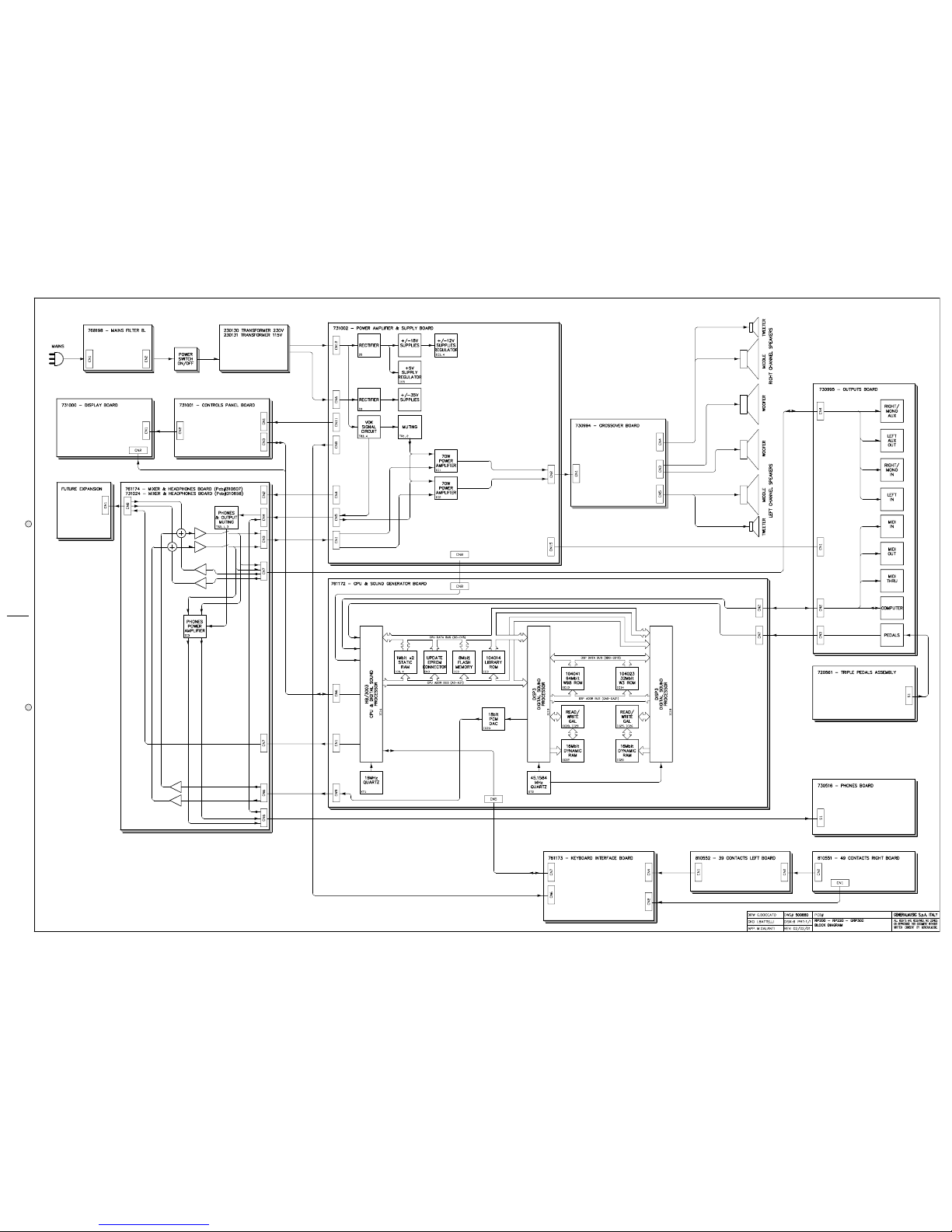
Block Diagram5
6
Keyboard Interface and L/R Contact Boards7
Power Amplifier & Supply, Outputs and Phones Boards
8
Cpu & Sound Generator Board Layout & Timing Table9
Spare Part List
10
12
Controls Panel and Display Boards
Cpu & Sound Generator Board
4
SERVICE MANUAL
CODE: 270247
Warnings
with the same signal name inscribed.
Address
ATTENTION
Observe precautions when handling electrostatic sensitive devices.
Notice
Service must be carried out by qualified personnel only. Any tampering carried out by unqualified personnel during the guarantee period
will forfeit the right to guarantee.
For a correct operation of the instrument, after having switched off, be careful to wait at least 3 seconds before switching on again.
To improve the device's specifications, the schematic diagrams may be subject to change without prior notice.
All components marked by this symbol have special safety characteristics, when replacing any of these components use only
manufacturer's specified parts.
The (µ) micro symbol of capacitance value is substituted by U.
The (
Ω
) omega symbol of resistance value is substituted by E.
The electrolytic capacitors are 25Vdc rated voltage unless otherwise specified.
All resistors are 1/8W unless otherwise specified.
All switches shown in the "OFF" position. All DC voltages measured to ground with a voltmeter 20KOhm/V.
✔
✔
✔
✔
✔
✔
✔
✔
✔
✔
✔
✔
✒
☎
❏ ❏
❏ ❏
❏ 2
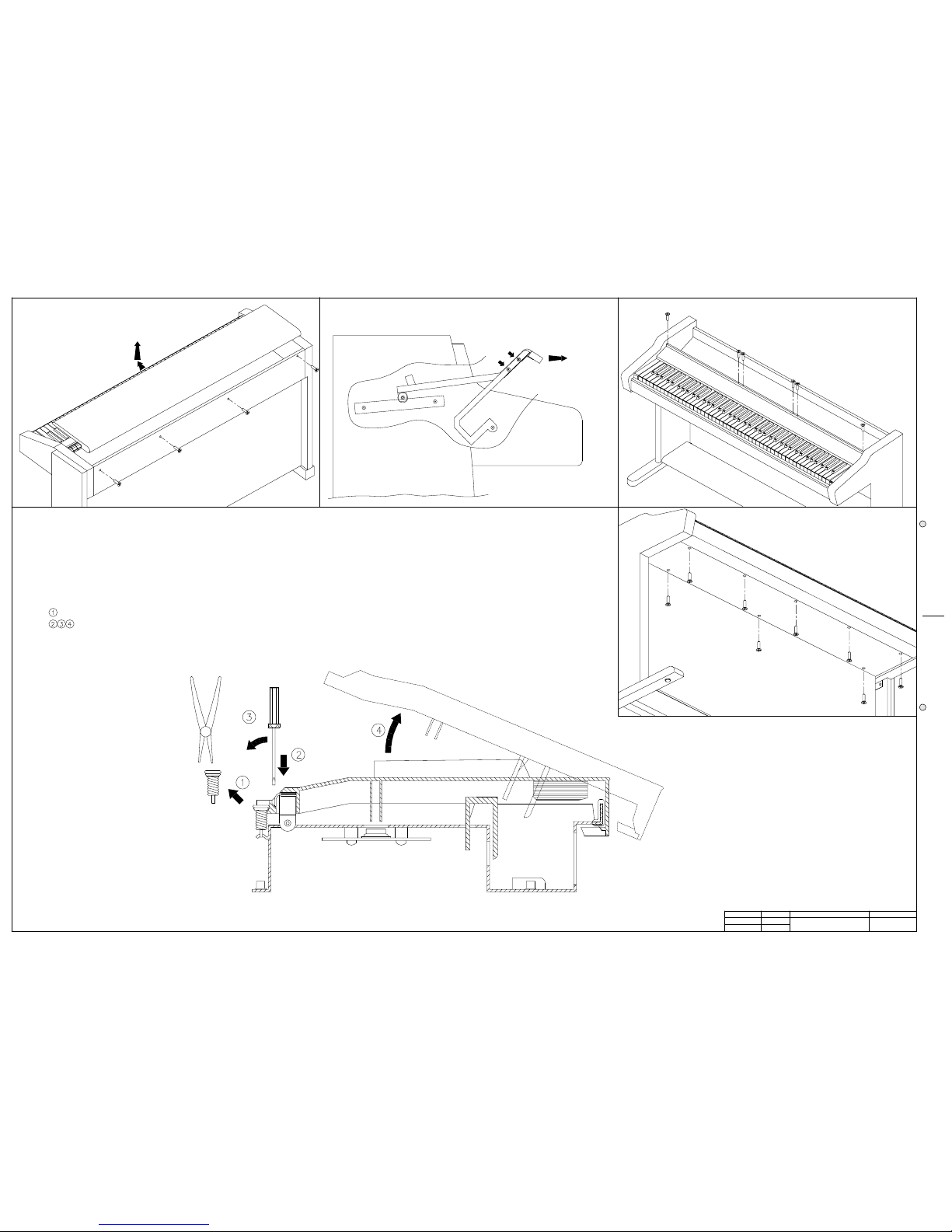
1) TO REMOVE THE COVER UNSCREW THE 4 SCREWS ON THE REAR, PULL THE COVER TOWARDS YOU AND LIFT IT UP.
3) TO REMOVE THE CONTROL PANEL UNSCREW THE SCREWS AT EACH END AND THE SCREWS THAT ANCHOR
4) TO REMOVE THE KEYBOARD UNSCREW THE 8 SCREWS UNDER THE KEYBOARD.
THE CONTROL PANEL SUPPORTS TO THE CHASSIS.
APP.
CKD
DRW
REV:
DISK:
DWG#
PRT:
PCB#
GENERALMUSIC S.p.A. ITALY
ALL RIGHTS ARE RESERVED, NO COPIES
WRITTEN CONSENT BY GENERALMUSIC.
OR REPRODUCE THIS DOCUMENT WITHOUT
G.Boccato
I.Battelli
M.Galanti
500935
1/1
01/02/01
RP220
Opening Instructions
& Keyboard disassembling
2) TO REMOVE THE KEYBOARD COVER UNSCREW THE FOUR SCREWS ON THE BARS (TWO FOR EACH SIDE),
AND PULL OUT THE KEYBOARD COVER.
NOTE: TO REMOVE A SHARP KEY BEFORE YOU MUST REMOVE THE NEAR NATURAL KEYS.
REMOVE THE KEY RETURN SPRING.
UNLOCK THE KEY APPLING NOT MUCH STRENGTH.
TP10
3
❏❏
❏❏
❏
rev. 02-02-01
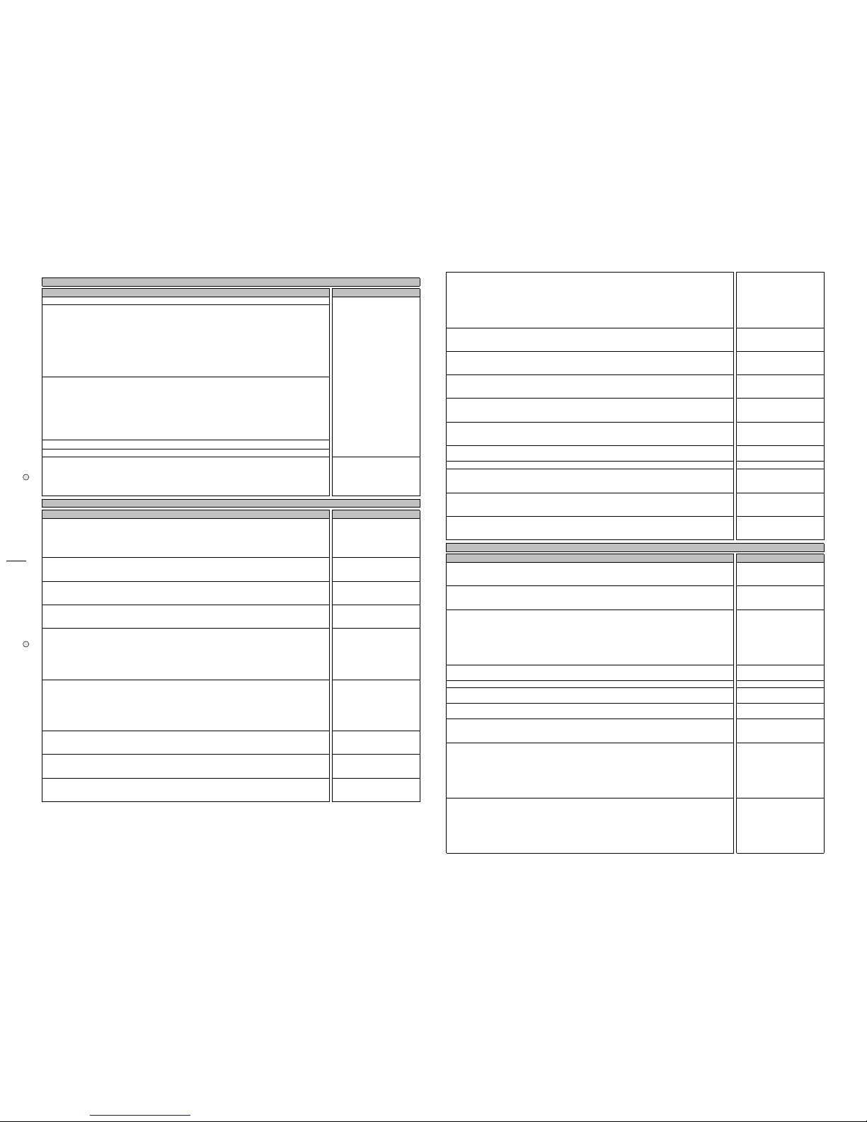
Operations Description Display
The following procedures must be executed subsequently in the specified order.
Before turn on the instrument check the jumpers setting on CPU & SOUND GENERATOR BOARD
corresponds at the model accordingly to the following table:
MODEL J4 J5 J3 J6 J2
RP200 GEM 1-2 1-2 1-2 1-2 1-2
RP200 BALDWIN 1-2 1-2 1-2 1-2 2-3
GRP300 GEM 1-2 1-2 1-2 2-3 1-2 v.2.00 or greater
GRP300 BALDWIN 1-2 1-2 1-2 2-3 2-3 v.2.00 or greater
RP220 GEM 1-2 1-2 2-3 1-2 1-2 v.2.02 or greater
RP220 BALDWIN 1-2 1-2 2-3 1-2 2-3 v.2.02 or greater
Remove the secondary fuses F1, F2, F3, located on POWER AMPLIFIER & SUPPLY BOARD; turn on the
instrument and verify the supply AC voltages:
(CN6) between pin1 and pin2 = 27,5 ± 1,5Vac
(CN6) between pin1 and pin3 = 27,5 ± 1,5Vac
(CN6) between pin2 and pin3 = 55 ± 3Vac
(CN12) between pin1 and pin2 = 16 ± 0,8Vac
(CN12) between pin1 and pin3 = 16 ± 0,8Vac
(CN12) between pin2 and pin3 = 32 ± 1,6Vac
Turn off the instrument, and put the fuses back on its holders.
Turn on the instrument and the appropriate welcome message appears on the display.
A few seconds later the led GRAND PIANO light.
Check the supply DC voltages on CPU & SOUND GENERATOR BOARD:
(CN8) between pin9 and pin7 = +5 ± 0,25Vdc
(CN8) between pin1 and pin4 = +12 ± 0,6Vdc
(CN8) between pin1 and pin5 = -12 ± 0,6Vdc
|INTERNAL PRESET|
| GRAND PIANO |
|GR.PIANO sel.:1|
RP200-220 GRP300 AUTOTEST PROCEDURE
Operations Description Display
The instrument starts in AUTOTEST mode turning on the instrument while pressing down the "GRAND
PIANO" button (pressing PRESET instead GRAND PIANO the procedure starts from LCD display test).
NOTE: Each time you press the "GRAND PIANO" button the autotest procedure proceeds to the next
step.
| RP98 |
| AUTOTEST |
| |
Set the default display contrast in the ± 6 range by pressing the DATA + or - buttons.
|CONTRAST = # |
| |
| |
The instrument shows the date, time and release version of the software loaded in flash memory.
| mmm dd yyyy |
|hh:mm:ss V #.##|
| |
The instrument asks if you want to update it, press GRAND PIANO to skip, the appropriate procedure
to update the software is explained further.
|EPROM to FLASH |
|push REC to prog|
| |
The instrument performs the flash memory data checksum and display it in hexadecimal value.
NOTE: the BT (boot) value must be EAAB for ver.2.00, if it does not correspond you can not update
software thru serial port but only with Update Software Board see more further.
For example version 2.02 has BT=EAAB PR=A5F4 and ALL=909F.
|Wait * |
|Eprom Checksum |
| |
|cks BT PR ALL|
| #### #### ####|
| |
The instrument performs the "LIBRARY" Rom memory data checksum and display it in hexadecimal
value.
|Wait * |
|Library Checksum|
| |
|Wait ok! |
|Checksum: A021|
| |
The instrument performs the RAM memory test showing the address checked.
|RAM MEMORY CHECK|
|addr 23BFFF OK|
| |
The LCD display test fades from light to dark and viceversa.
|❚ ❚ ❚ ❚ ❚ ❚ ❚ ❚ ❚ ❚ ❚ ❚ ❚ ❚ ❚|
|❚ ❚ ❚ ❚ ❚ ❚ ❚ ❚ ❚ ❚ ❚ ❚ ❚ ❚ ❚|
|❚ ❚ ❚ ❚ ❚ ❚ ❚ ❚ ❚ ❚ ❚ ❚ ❚ ❚ ❚|
Check that all leds are lighting.
|--- LED TEST ---|
|Are all leds on?|
| |
RP200-220 GRP300 INITIAL CHECK
| RP200 |
| REALPIANO |
| GEM |
| PIANOVELLE |
| RP200 |
| BALDWIN |
| GRP300 |
| REALPIANO |
| GEM |
| PIANOVELLE |
| GRP300 |
| BALDWIN |
| RP220 |
| REALPIANO |
| GEM |
| PIANOVELLE |
| RP220 |
| BALDWIN |
Check the VOLUMES ranges from 0 to 127.
Check all buttons (except GRAND PIANO) pressing their one at a time and checking that corresponding
led lights, pressing PAGE UP and DOWN buttons the display shows "U" and "D", pressing DATA + and buttons the display shows "+" and "-", pressing MASTER EQ and DSP buttons the display shows an
"X" in 1 and 2 digits, pressing UP, LEFT, DOWN and RIGHT buttons the display shows an "X" in 3, 4, 5
and 6 digits respectively.
| |Button test |
| |Vol:0 |
| 123456|
|U|Button test +|
|D|Vol:127 -|
| XXXXXX|
Check the SOFT and SUSTAIN pedals, pressing each one the value change from 0 (released) to 127
(pressed), the DAMPER pedal varying its value continuosly from 0 (released) to nearly 127 (pressed).
|Soft Sust Damp|
| 0 0 0|
| |
Check the MIDI I/O connecting the MIDI OUT and MIDI IN sockets by a MIDI cable.
|TEST MIDI IN/OUT|
|LOOP DETECTED OK|
| |
Check COMPUTER I/O shorting pin 3 and pin 5 on the COMPUTER socket, check with the oscilloscope a
4Vpp (1Mhz) signal on pin 1, set volume to half stroke.
|TST COMPUTER I/O|
|LOOP DETECTED OK|
| |
The instrument generates a 1KHz sinusoidal signal in both audio channels reading data from 104043
ROM. VOLUME controls the amplitude of signal and TRANSPOSE b and # buttons controls the
frequency from 10Hz to 2756Hz.
| SINUS. SWEEP |
|Freq. 1000 Hz|
| |
Re-set the frequency at 1KHz and check HEADPHONES and AUX outputs with the oscilloscope inserting
a stereo jack in the left phones socket (speakers will go be silent) and two mono jack in the AUX OUT
sockets and set volume to its maximum.
Now verify the following level of signals:
Phones output without load = 5,7 ± 1.1Vpp and AUX output = 0,8 ± 0,16Vpp
Set the VOLUME to minimum.
Apply a sinusoidal signal of 0.730Vpp at 1KHz with a generator to the AUX IN left and right sockets
and verify the signal output:
AUX output = 1,35 ± 0.07Vpp
The instrument generates a tone signal in both audio channels reading data from 104023 ROM.
|TONE ON 104023 |
| |
| |
Autotest is over, turn off the instrument.
|TEST END: SWITCH|
|POWER TO RESTART|
| |
RP200-220 GRP300 O.S. UPDATING PROCEDURE up to ver. 2.00 with Updating Software Board (751180)
Operations Description
Display
Start with the instrument in AUTOTEST mode as described above and press GRAND PIANO 2 times
until the display show the software version loaded in flash memory.
| mmm dd yyyy |
|hh:mm:ss V #.##|
| |
Press GRAND PIANO to skip this procedure.
|EPROM to FLASH |
|push REC to prog|
| |
The instrument performs the flash memory data checksum and displays it in hexadecimal value.
|Wait * |
|Eprom Checksum |
| |
|cks BT PR ALL|
| #### #### ####|
| |
Compare the software version and checksum with the value imprinted onto the EPROM, if one of these
does not match, the system must be upgraded, proceed to the next step.
Turn off the instrument.
Insert the EPROM BOARD (where the operating system is stored) in the CN3 connector located on CPU
& SOUND GENERATOR BOARD.
Start with the instrument in AUTOTEST mode as described above and press GRAND PIANO 3 times.
When the display shows this message press REC.
|EPROM to FLASH |
|push REC to prog|
| |
The instrument erases the previous data in flash memory. After which the instrument displays the
amount of memory programming and finally the operation successful. If the programming fails check
the EPROM BOARD connection and repeat this procedure from start.
|EPROM to FLASH |
|erasing |
| |
|EPROM to FLASH |
|prog: 1024/1024K|
| |
The instrument performs the eprom memory data checksum and display it in hexadecimal value,
compare this value with the value imprinted onto the EPROM: if it matches the EPROM is good.
|Wait * |
|Eprom Checksum |
| |
|cks BT PR ALL|
| #### #### ####|
| |
❏ ❏
❏ ❏
❏ 4
Turn off the instrument and disconnect the EPROM BOARD.
Start with the instrument in AUTOTEST mode as described above and press GRAND PIANO 2 times
until the display show the new software version loaded in flash memory.
| mmm dd yyyy |
|hh:mm:ss V #.##|
| |
Press GRAND PIANO to skip this procedure.
|EPROM to FLASH |
|push REC to prog|
| |
The instrument performs the flash memory data checksum and display it in hexadecimal value,
compare this value with the value imprinted onto the EPROM: if it matches the procedure has been
executed succesfully.
|Wait * |
|Eprom Checksum |
| |
|cks BT PR ALL|
| #### #### ####|
| |
The procedure proceed as described in AUTOTEST section, if you do not want to check the rest of the
instrument simply turn off it.
RP200-220 GRP300 O.S. UPDATING PROCEDURE from Serial Port (COMPUTER) ver. 2.xx or greater
Operations Description Display
NOTE: This procedure is valid only if the software version installed on the piano is the 2.00 or greater.
Some additional tips and advices are included in the Flashblaster Firmware Update Disk. The disk
containing the Fblaster program can also be downloaded by internet at generalmusic web site
(www.generalmusic.com) or required at support@generalmusic.com
Connect the serial cable between the COMPUTER of the piano and the RS232 COM port of the
computer (PC-Ibm or compatible).
Insert the disk in the drive A (or whatever your 3.5" drive is assigned to), open the contents of drive A
and double click on the fblaster.exe file.
From the OPTIONS/SETTINGS menu, make sure that the TEST AND PROGRAM choice is selected. This
is very important.
Turn on the piano, while holding down the REC button until the display shows:
|READY TO UPDATE |
| |
| |
Click with the mouse on the GO! button or, from the ACTION menu, select EXECUTE (ALT+A, E). The
piano display appears as follows:
|TESTING... |
|n1/n2 PACKETS |
| |
At the end of the test the following display appears:
| TEST OK |
| |
| |
After a short time, the following display appears:
|ERASING... |
| |
| |
You are now erasing the old operating system from FLASH memory. When the system is erased, the
following display appears as your new operating system is installed into Flash Memory:
|UPDATING... |
|n1/n2 PACKETS |
| |
When the entire update procedure is completed, the following display appears:
|UPDATE_OK:SWITCH|
|POWER TO RESTART|
| |
The update has now been successfully completed. Turn off the power switch on the piano, and turn it
back on again to use your updated instrument.
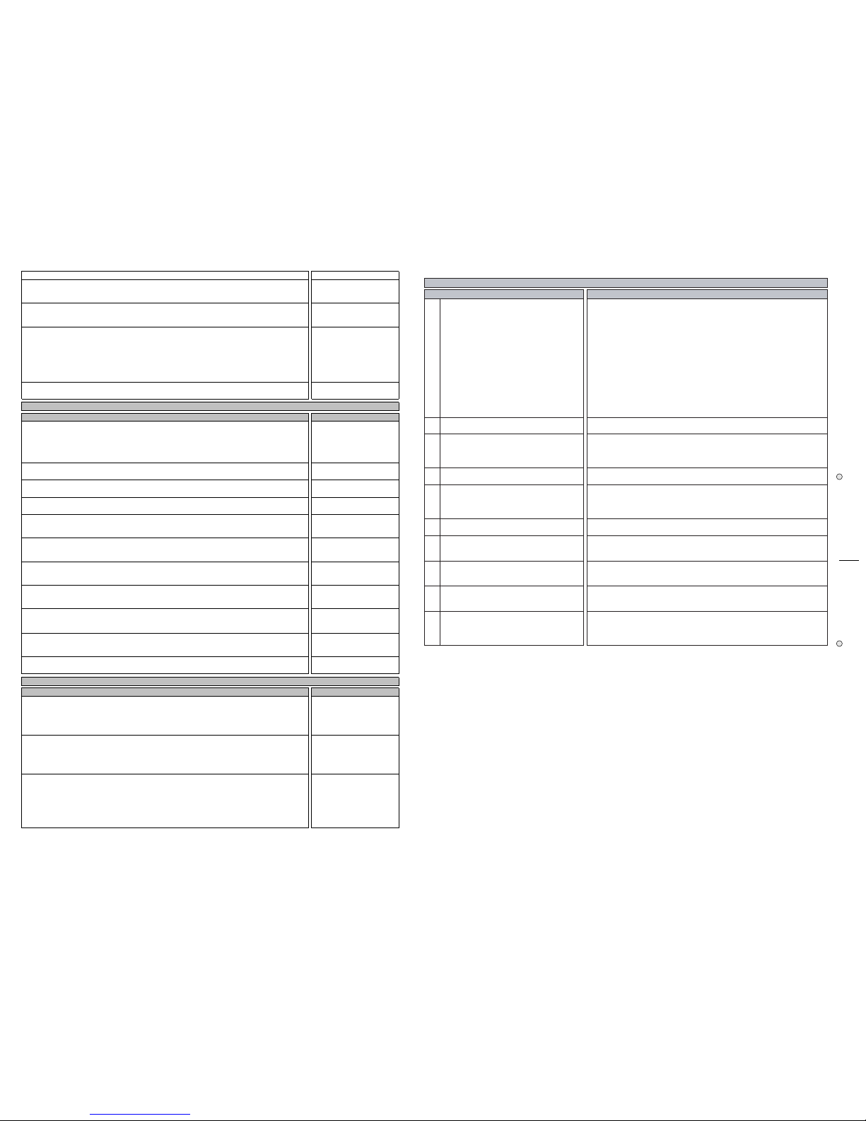
RP200-220 GRP300 Some Repairing Tips
Operations Description Display
This message could be appear if an error occur on the communication channel.
Possible solutions:
1) inconsistent data received on MIDI or COMPUTER input socket, check the ratings of the device
connected to the piano.
2) if the error persist, try to replace Outputs Board first and CPU board second.
|MIDI SCI error |
| |
| |
This message could be appear if an error occur on the communication channel.
Possible solutions:
1) verify all the connections between Keyboard Interface Board and the CPU board.
2) if the error persist, try to replace Keyboard Interface Board first and CPU board second.
|VALIS SCI error |
| |
| |
This message could be appear if an error occur on the communication between CPU and DISP3 chips.
Possible solutions:
1) verify all the tracks, solders and components between CPU and DISP3 chips as shown in
schematics.
2) if the error persist, replace the CPU board and send back to generalmusic the failed CPU board.
|Disp Failure |
| |
| |
rev. 19-07-00
Questions Answers
1
What do the pedals make?
Soft (left pedal):
This pedal is a switch control pedal (on/off) and affects the timbre of the
instrument such that it plays softer, allowing you to continue using the same
playing style at a lower volume.
Sostenuto only for some models (centre pedal):
This pedal is a switch control pedal (on/off) which sustains the notes of the key
currently depressed, all new notes played after having depressed the pedal are
not affected, this pedal operates like a grand piano centre pedal.
Damper (right pedal):
This pedal applies the sustain effect to all notes released. If you release a note
after depressing the damper, the note will proceed towards its natural decay
according to the type of sound played.
The Damper pedal is particularly effective with Piano type sounds, it is controlled
by a "Damper Physical Model" patented by Generalmusic.
2
Why do the uppermost keys play always
sustained?
For all piano sounds the notes from E6 to C8 are automatically sustained such as
in an acoustic piano.
3
Why do all pedals work in reverse mode?
The instrument reads the status of the pedals at the power on and assume this
status (normally open or normally closed depends by the type of pedal) as the
default status in the rest position.
The pedals must be inserted before you switch on the instrument.
4
Why do some pedal work in reverse mode?
For the same reason explained first you have not to press a pedal while the
instrument is switched on and until it is ready to use.
5
I have replaced the DAMPER pedal
potentiometer, how do I let position it correctly?
Set the potentiometer to have about 700 ohm between pin 5 and 1 of DIN plug
with the pedal at the rest position.
Note: the Damper potentiometer have a special resistive stroke, when you
replace it use the manufacturer's part only (code 070556).
6
How can I do a complete SYSTEM RESET?
Turn on the instrument while pressing down the "General" button.
Each time you do an autotest procedure a system reset is performed.
7
Why does not the instrument respond correctly
to the key pressed on keyboard after I have
replaced the CPU Board?
If the CPU Board replaced is the right type check the jumper setting on it as
described on this service manual and execute a complete Autotest.
8
Why does not the instrument respond correctly
to the button pressed on controls panel after I
have replaced the CPU Board?
If the CPU Board replaced is the right type check the jumper setting on it as
described on this service manual and execute a complete Autotest.
9
Why does not the instrument respond correctly
to the pedal pressed after I have replaced the
CPU Board?
If the CPU Board replaced is the right type check the jumper setting on it as
described on this service manual and execute a complete Autotest.
10
Why does not the Instrument retain the user
presets and data?
After a long period of inactivity may be occur that the internal battery backup
have not a sufficient time for re-charging during the normal activity, try to leave
the instrument switched on for about 12-14 hours. Afterwards if the instrument
will lost the data again, replace the battery.
RP series FAQ
5
❏❏
❏❏
❏
 Loading...