

General Music Pianovelle PS2500, Pianovelle GPS2500 Service Manual
11
11
1
❒❒
❒❒
❒
CODE:270189
Index&Warnings
Soldering point.
Male connector.
Female connector.
M/F faston connector.
Test point.
Supply voltage.
Logic supply ground.
Analog supply ground.
Signal ground.
Chassis ground.
Flag joined with one or more flags with the same signal name inscribed.
GENERALMUSIC S.p.A. SalesDivision :47048 S.Giovanni in Marignano(RN) ITALY -V iadelle Rose, 12 -
tel. 0541/959511- tlx 550555 GMUSIC I- fax 0541/957404
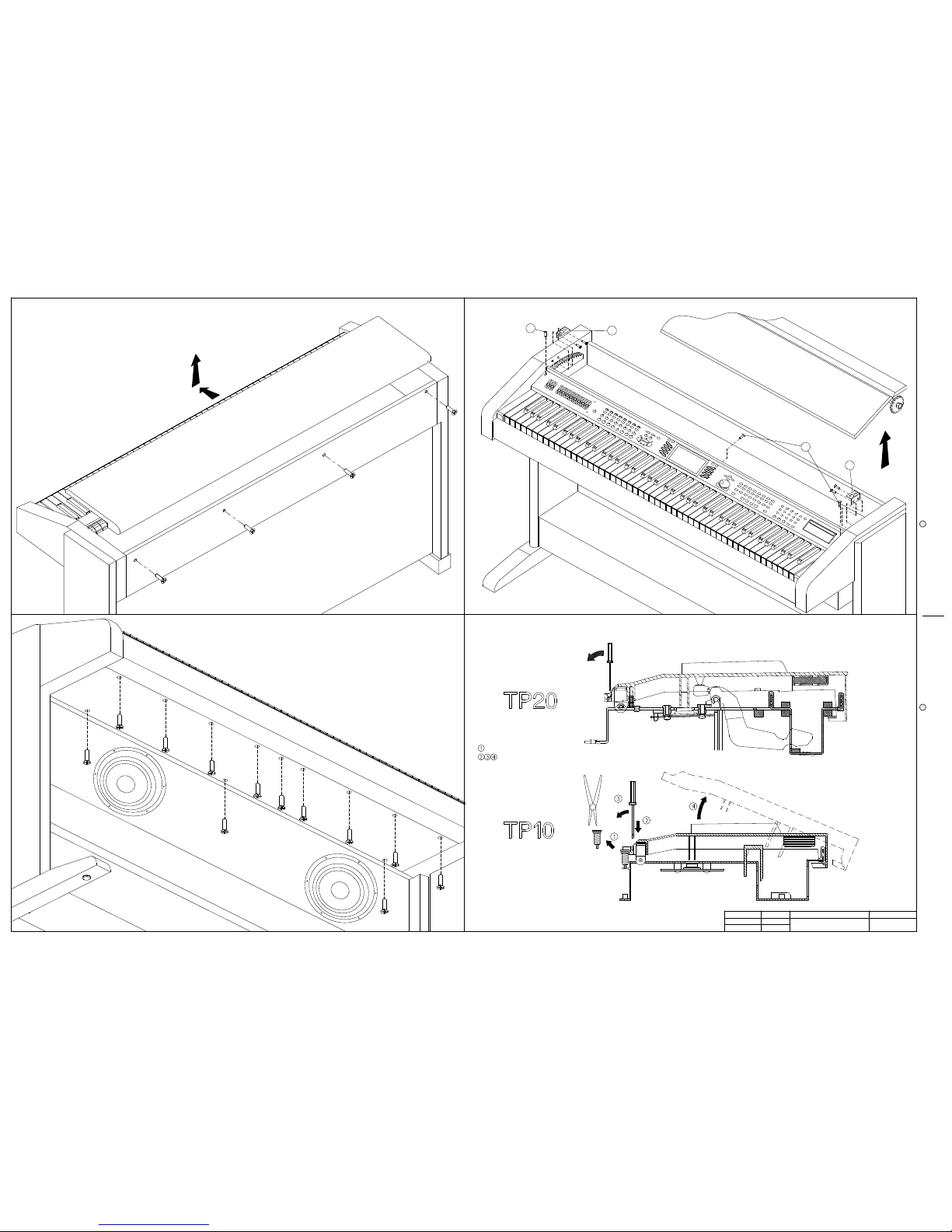
PS 2500 Opening Instructions - KeyboardDisassembling
GPS 2500 Opening Instructions - Keyboard Disassembling
PS 2500 Cabinet Assembly 1
PS 2500 Stand & Controls Assembly 2
GPS 2500 Cabinet Assembly
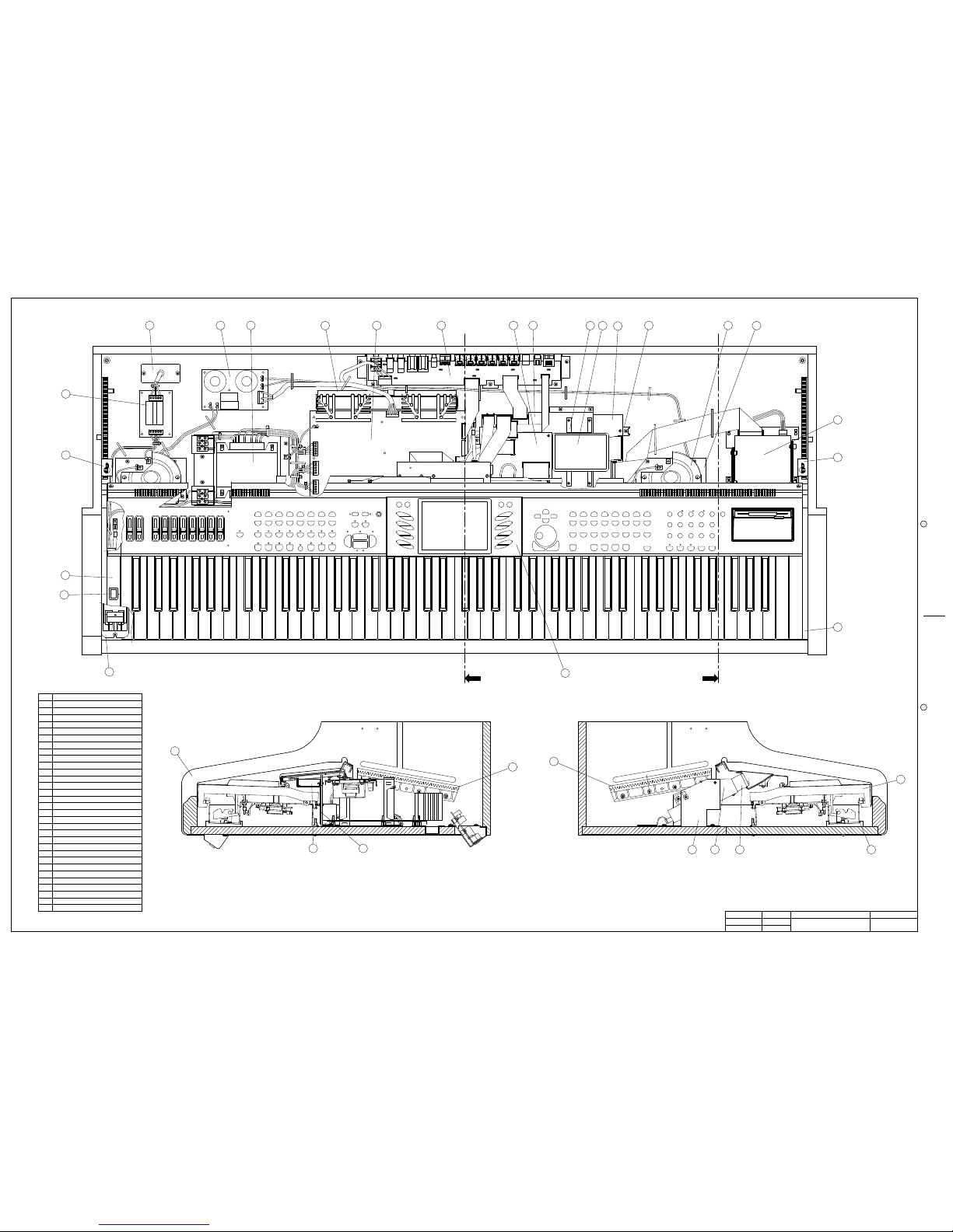
Block Diagram
Power Amplifier & Supply, Phones, Cross Over and Control & Midi I/O Schematic Diagrams
Power Aamplifier. & Supply, Control Midi I/O, Keyboard Interface and Cross Over PCB Layouts
Slider, L & R Controls Panel and Controls Panel Interface Schematic Diagrams
Right & Left Control Board - Control Panel Interface PCB Layout
CPU & Sound Generator Board (Part 1/2)
CPU & Sound Generator Board (Parts 2/2)
Optional Kits Mounting Instructions
Spare Part List
L & R Contacts and Keyboard Interface Schematic Diagrams
Timing Diagram & Adjustment Table
Audio/Video Interface Schematic Diagram
CPU & Sound Generator and Audio/Video Interface PCB Layouts
2
3
4
5
6
7
8
9
10
11
12
13
14
15
16
17
18
19
Notice
Service must be carried out by qualified personnel only.Any tampering carried out by unqualified personnel during the guarantee
period will forfeit the right to guarantee.
For a correct operation of the instrument, after having switched off, be careful to wait at least 3 seconds before switching on again.
To improve the device's specifications, the schematic diagrams may be subject to change without prior notice.
SchematicNotes
All components marked by this symbol have special safety characteristics, when replacing any of these components use only
manufacturer's specified parts.
The ( ) micro symbol of capacitance value is substituted by U. The (µΩ) omega symbol of resistance value is substituted by E.
The electrolytic capacitors are 25Vdc rated voltage unless otherwise specified. All resistors are 1/8W unless otherwise specified.
All switches shown in the "OFF" position. All DC voltages measured to ground with a voltmeter 20KOhm/V.
ATTENTION
Observeprecautions when handling
electrostatic sensitive devices
SERVICE MANUAL
Schematic Diagrams
❒❒
❒❒
❒
2
C
D
C
D
C
D
C
C
C
D
D
C
C
C
D
C
D
C
D
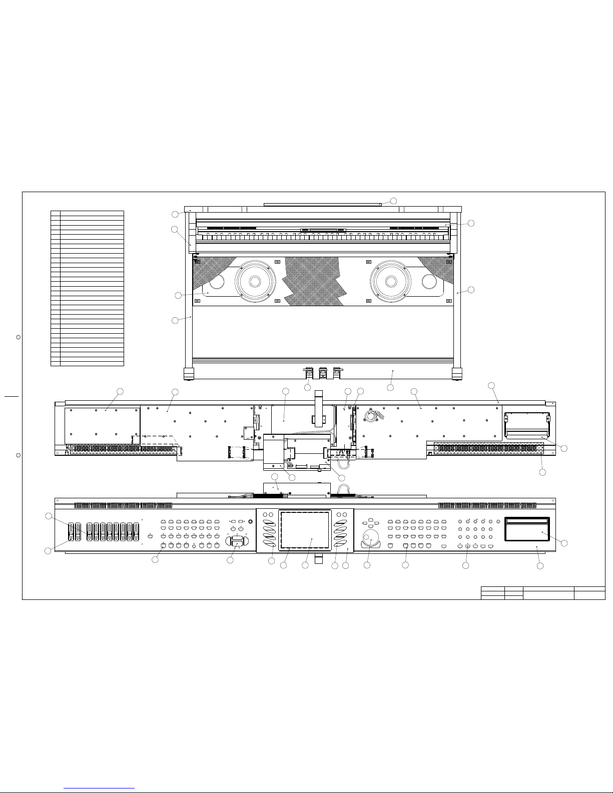
To remove the TP20 keyboard unscrew 11 screws (C) under the piano.
To remove the TP10 keyboard unscrew 8 screws (D) under the piano.
Unscrew the four screws at the rear of instrument.
Disconnect the instrument from the mains.
Remove the top panel in the direction as shown.
PS2500 - To Open the Instrument
DRW
APP.
CKD
WRITTEN CONSENT BY GENERALMUSIC.
OR REPRODUCE THIS DOCUMENT WITHOUT
ALL RIGHTS ARE RESERVED, NO COPIES
GENERALMUSIC S.p.A. ITALY
PART:
DWG#
DISK:
REV:
PCB#
Consorte
Riccobelli
Boccato
550115
19/12/96
42
& Keyboard Disassembling
PS2500 Opening Instructions
1/1
NOTE: Before you remove a natural key you must remove the keyboard, if you remove a sharp key this operation is not necessary.
To remove a key insert a screwdriver or other similar object in the split at the key back, apply a light pressure and push in the direction shown.
NOTE: To remove a sharp key before you must remove the near natural keys.
Remove the key return spring.
Unlock the key appling not much strength
Remove the keyboard cover (slide it through the lateral guides).
To unlock the controls panel unscrew the three screws (B).
B
Remove the two locking plates (A) from the sides.
A
B
A
33
33
3
❒❒
❒❒
❒
DRW
APP.
CKD
WRITTEN CONSENT BY GENERALMUSIC.
OR REPRODUCE THIS DOCUMENT WITHOUT
ALL RIGHTS ARE RESERVED, NO COPIES
GENERALMUSIC S.p.A. ITALY
PART:
DWG#
DISK:
REV:
PCB#
Consorte
Riccobelli
Boccato
550116
20/12/96
42
& Keyboard Disassembling
GPS2500 Opening Instructions
1/1
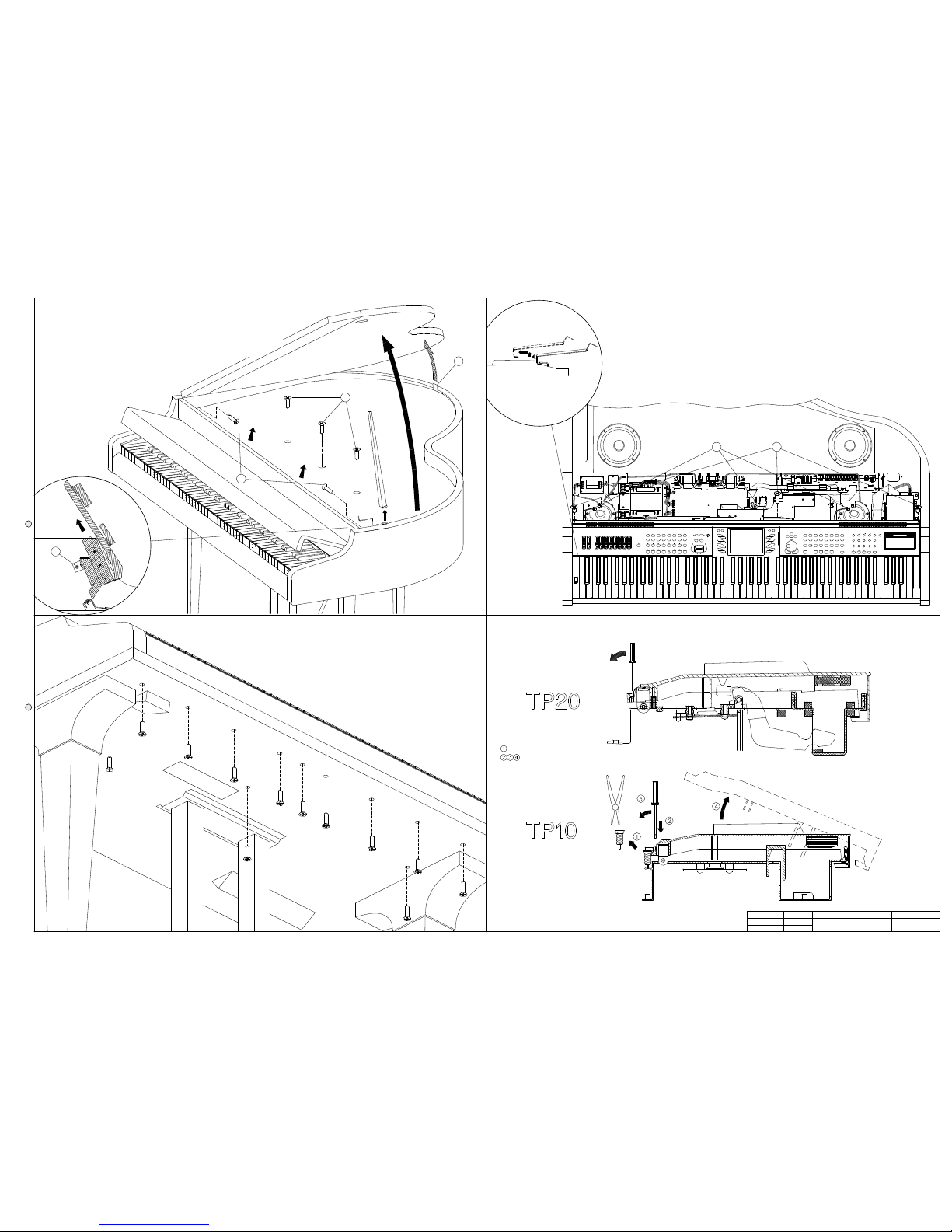
C
To remove the TP10 keyboard unscrew 8 screws (D) under the piano.
To remove the TP20 keyboard unscrew 11 screws (C) under the piano.
D
C
D
D
C
D
C
C
C
D
C
C
C
GPS2500 - To Open the Instrument
Remove the protection panel by lifting it from the rear (B). Unscrew the two lateral screws (C).
Disconnect the instrument from the mains. Lift the cover and unscrew the three screws (A).
Note: to operate without difficulty two people are required.
Lift up the front panel with the keyboard cover raised.
NOTE: To remove a sharp key before you must remove the near natural keys.
C
C
D
C
D
D
C
Unlock the key appling not much strength
To remove a key insert a screwdriver or other similar object in the split at the key back, apply a light pressure and push in the direction shown.
NOTE: Before you remove a natural key you must remove the keyboard, if you remove a sharp key this operation is not necessary.
Remove the key return spring.
A
B A
B
jumpers of the controls panel, rest the panel temporarily on the keyboard.
pull the controls panel toward you and raise it.
To re-assemble the piano follow the instructions in reverse order.
To easy access to the internal circuitry, you must remove the controls panel.
Unscrew the three screws (A), disconnect the three grounding jumpers (B),
To install the optional accessories it is not necessary to disconnect other
❒❒
❒❒
❒
4
DRW
APP.
CKD
WRITTEN CONSENT BY GENERALMUSIC.
OR REPRODUCE THIS DOCUMENT WITHOUT
ALL RIGHTS ARE RESERVED, NO COPIES
GENERALMUSIC S.p.A. ITALY
PART:
DWG#
DISK:
REV:
PCB#
FALCONI
BOCCATO
PALANGHI
550117
17-12-96
42
CABINET ASSEMBLY
PS2500
1/1
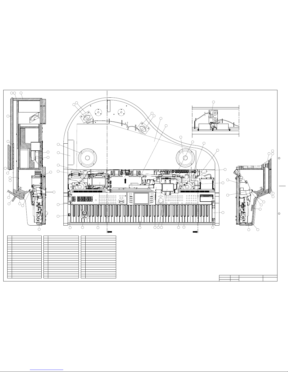
2
6
5
16
13
17
18
31
3
19
15
30
27
28
29
21
20 26
25
4
Ref.
1
2
3
Description
CABINET
HEATSINK GRID
PHONES BOARD
11
10
14
12
13
16
15
9
5
4
6
8
7
LEFT COVER CLAMP
KEYBOARD SLOPE SUPPORT
KEYBOARD ASSEMBLY (TP20 OR TP10)
CONTROL PANEL REAR SUPPORT
CONTROL PANEL FRONT SUPPORT
RIGHT COVER CLAMP
MAINS ASSEMBLY
MAINS SWITCH
RIGHT PANEL SUPPORT
LEFT PANEL SUPPORT
RACK
CONTROLS & MIDI I/O BOARD
MAINS FILTER BOARD
POWER AMPLIFIER & SUPPLY BOARD
CROSSOVER BOARD
TRANSFORMER ASSEMBLY
17
18
19
CPU & SOUND GENERATOR BOARD
CPU & SOUND GENERATOR BOARD SUPPORT
30
AUDIO/VIDEO INTERFACE BOARD
DISK DRIVE GROUP SUPPORT
3.5" DISK DRIVE
DISK-DRIVE SUPPORT
HARD DISK
HARD DISK BRACKET
TWEETER SUPPORT
25
22
21
20
24
23
26
27
28
29
TWEETER
CONTROLS PANEL (see next page)
31
1
11
10
7
7
24 22
23
8
9
View B
View B
View A
View A
AUDIO/VIDEO INTERFACE BOARD & H. D. SUPPORT
14
12
23
55
55
5
❒❒
❒❒
❒
DRW
APP.
CKD
WRITTEN CONSENT BY GENERALMUSIC.
OR REPRODUCE THIS DOCUMENT WITHOUT
ALL RIGHTS ARE RESERVED, NO COPIES
GENERALMUSIC S.p.A. ITALY
PART:
DWG#
DISK:
REV:
PCB#
Falconi
Boccato
Palanghi
550118
18-12-96
42
ASSEMBLY
STAND & CONTROLS PANEL
1/1
13
18
19
DISPLAY FRAME
DISPLAY GLASS
DISPLAY RIGHT RUBBER KEY-PAD
CONTROL PANEL
DISPLAY SUPPORT
CLOTH FOR PANEL SLITS
DISK-DRIVE FRAME
LCD DISPLAY ASSEMBLY
6
7
8
4
3
1
Ref.
2
5
14
Description
COVER
KEYBOARD COVER
SPEAKER BOX
LEFT SIDE LEG
CABINET
DIAL KNOB
TRIPLE PEDAL ASSEMBLY
<EDIT> RUBBER KEY-PAD
SLIDERS BOARD
<START/STOP> RUBBER KEY-PAD
<SOUND GROUP> RUBBER KEY-PAD
DISPLAY LEFT RUBBER KEY-PAD
MUSIC STAND
PEDAL CROSS-BAR
AC-DC ADAPTER SCREEN
CONTROL PANEL INTERFACE BOARD
SLIDER POTENTIOMETER KNOB
SLIDER POTENTIOMETER FRAME
RED FELT (1230x12x1.5)
LEFT CONTROLS PANEL BOARD
RIGHT CONTROLS PANEL BOARD
<STYLE GROUP> RUBBER KEY-PAD
RIGHT SIDE LEG
29
28
26
25
22
23
24
20
21
18
17
19
15
14
12
11
13
9
10
16
27
31
32
30
12
3
9
7
21
23
20
6
8
11
22
10
1
2
3
24
15
28
5
30
29
32
4
25
16
17
27
31
3
BOARDS SUPPORT
25
26
❒❒
❒❒
❒
6
DRW
APP.
CKD
WRITTEN CONSENT BY GENERALMUSIC.
OR REPRODUCE THIS DOCUMENT WITHOUT
ALL RIGHTS ARE RESERVED, NO COPIES
GENERALMUSIC S.p.A. ITALY
PART:
DWG#
DISK:
REV:
PCB#
Falconi
Boccato
Pannelli
550119
20-01-97
42
Cabinet Assembly
GPS2500
1/1
Hole Closing Sheet
Hole Closing Sheet
Hinge Between Keyb. Cover and Front P.
Hinge Between Rev. Cover and Cover
Net For Speaker Panel
Adhesive Beating Rubber
Washer For Cover Stand
Hinge Between Cabinet and Cover
Hinge For Cover Stand
Audio/Video Interface Board
Hard Disk Support
Hinge Between Keyb. Front & Top Covers
Description
27
4
Keyboard Cover
Description
Speaker Panel1
Ref.
19
Ref.
Cpu & Sound Generator Board
Power Amplifier & Supply Board
Revolving Cover
Control Panel Assembly
Mains Filter Board
Revolving Keyboard Cover
Front Cross Bar
Cabinet Chassis
Front Panel
Music Stand
Cover Stand
Speaker Box
3
2
4
5
10
7
6
8
9
11
14
13
12
Cover
15
21
20
22
23
28
25
24
27
26
30
29
32
31
33
38
Mains Assembly
Power Switch
Transformer Assembly
Description
37
Ref.
Tweeter Support
8" Woofer
Hinge For Music Stand
Tweeter Support
Cpu Board Support
Right Keyb. Cheek Block
3.5" Disk Drive
6" Woofer
Dome Tweeter Speaker
Cone Tweeter Speaker
Accessories Support
Keyboard Assembly
Left Keyb. Cheek Block
49
48
47
46
44
45
39
40
41
42
43
50
Heatsink Net
Adhesive Felt
Speaker Net
Black Cloth
51
6
Controls & Midi I/O Board
Cross-Over Board
Phones Assembly
18
16
17
35
34
36
31
Disk Drive Support
Cheek Support
Drive Support Stand
53
54
52
Hard Disk
22
38
32
46
2
10
43
44
39
20
13
32
24
49
11
31
41
42
45
1
View A
3
26
18
View A
19
21
12
29
525354
36
View B
23
27
View C
33
40
30
5
26
15
14
16
25
7
9
30
37
34
35
View B
10
47
48
50
8
51
View C
17
31
 Loading...