

General Music RP100 GEM, RP150 GEM, RP100 BALDWIN, RP150 BALDWIN, RP90 GEM Service Manual
...Page 1
1
JJ
JJ
J
Index
Soldering point.
Male connector.
Female connector.
M/F faston connector.
Test point.
Supply voltage.
Logic supply ground.
Analog supply ground.
Chassis ground.
Earth ground.
Flag joined with one or more flags
GENERALMUSIC S.p.A. Sales Division: 47842 S.Giovanni in Marignano (RN) ITALY - Via delle Rose, 12 - tel. 0541/959511 - fax 0541/957404
GENERALMUSIC on the NET: http://www.generalmusic.com
2
3
Opening Instructions & Keyboard disassembling
6
7
RP200 Initial Check, Autotest Procedure, Updating Procedure
8
RP100-150 Initial Check, Autotest Procedure, Updating Procedure
RP100 - Power Amplifier & Supply, Pedals, Phones, Outputs Boards
RP200 Block Diagram
4
SERVICE MANUAL
L
CODE: 270212
M
Warnings
with the same signal name inscribed.
Address
ATTENTION
Observe precautions when handling electrostatic sensitive devices.
Notice
Service must be carried out by qualified personnel only.Any tampering carried out by unqualified personnel during the guarantee period
will forfeit the right to guarantee.
For a correct operation of the instrument, after having switched off, be careful to wait at least 3 seconds before switching on again.
To improve the device's specifications, the schematic diagrams may be subject to change without prior notice.
All components marked by this symbol have special safety characteristics, when replacing any of these components use only
manufacturer's specified parts.
The (µ) micro symbol of capacitance value is substituted by U.
The (
Ω
) omega symbol of resistance value is substituted by E.
The electrolytic capacitors are 25Vdc rated voltage unless otherwise specified.
All resistors are 1/8
Ω
unless otherwise specified.
All switches shown in the "OFF" position. All DC voltages measured to ground with a voltmeter 20KOhm/V.
9
10
RP150 - Power Amplifier & Supply, Pedals, Phones, Outputs Boards
12
13
Keyboard Interface & Contacts Boards
14
RP200 - Power Amplifier & Supply, Pedals, Mixer & Phones Aplifier, Phones, Outputs Boards
RP100-150 Cpu & Sound Generator Board
RP200 Controls Panel & Display Boards
11
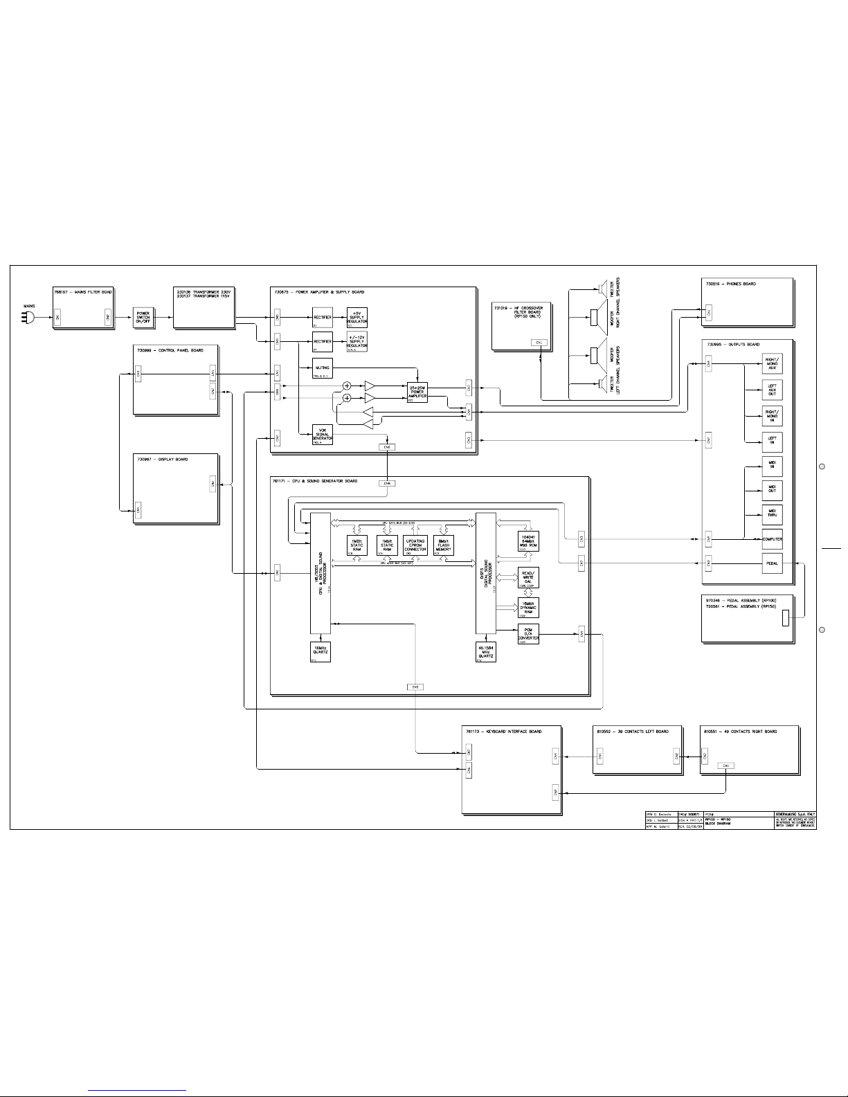
RP100-150 Block Diagram
RP100-150 Controls Panel & Display Boards
15
Timing Table & 310603 Board Layout
16
RP200 Cpu & Sound Generator Board Part 1 of 2
17
RP200 Cpu & Sound Generator Board Part 2 of 2
18
RP100 and RP150 Spare Part List
19
RP200 Spare Part List
Page 2
J J
J J
J 2
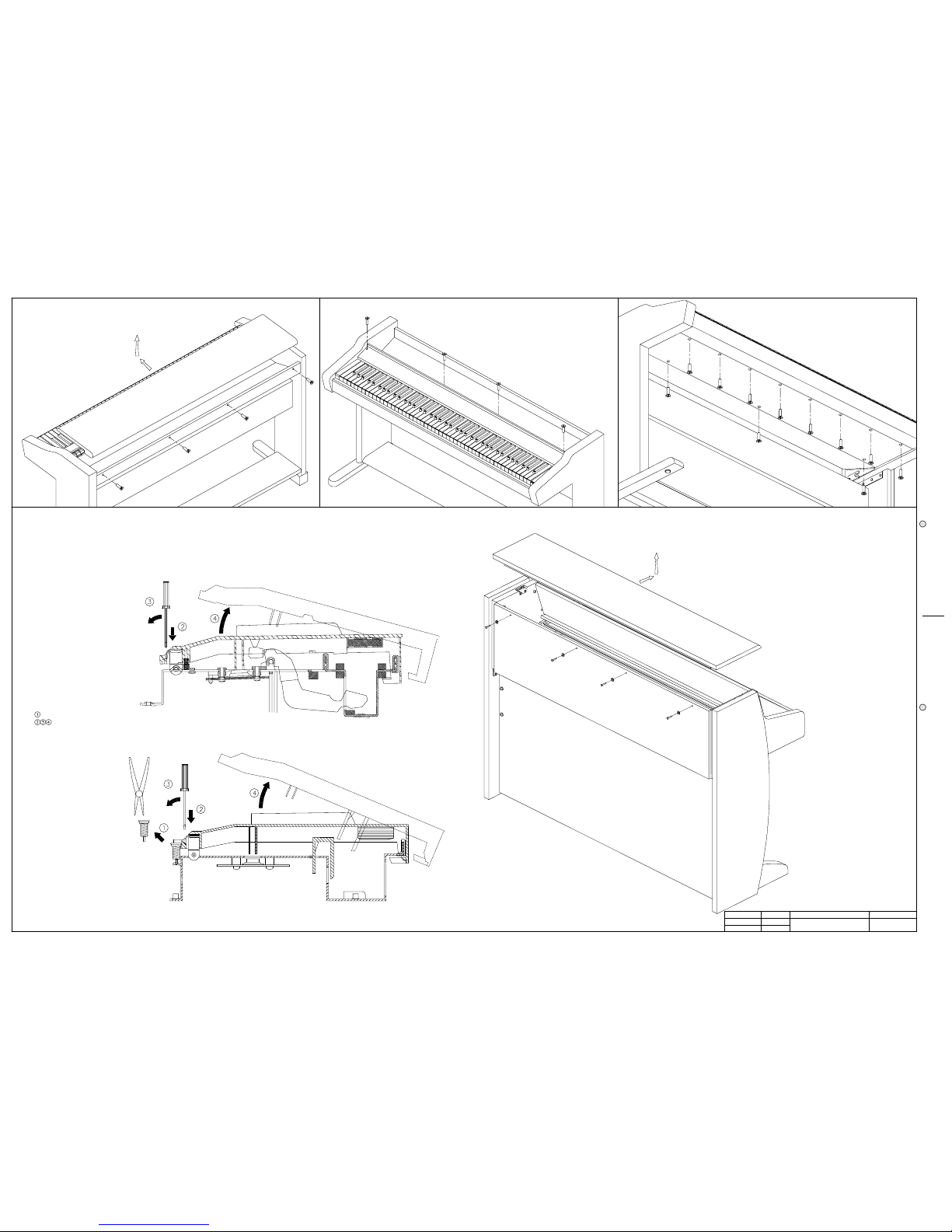
1) TO REMOVE THE COVER UNSCREW THE 4 SCREWS ON THE REAR, PULL THE COVER TOWARDS YOU AND LIFT IT UP.
2) TO REMOVE THE CONTROL PANEL UNSCREW THE SCREWS AT EACH END AND THE SCREWS THAT ANCHOR
REMOVE THE KEY RETURN SPRING.
NOTE: TO REMOVE A SHARP KEY BEFORE YOU MUST REMOVE THE NEAR NATURAL KEYS.
UNLOCK THE KEY APPLING NOT MUCH STRENGTH.
4) TO REMOVE A KEY INSERT A SCREWDRIVER OR OTHER SIMILAR OBJECT IN THE SPLIT AT THE KEY BACK, APPLY A LIGHT PRESSURE AND PUSH IN THE DIRECTION SHOWN.
NOTE: BEFORE YOU REMOVE A NATURAL KEY YOU MUST REMOVE THE KEYBOARD, IF YOU REMOVE A SHARP KEY THIS OPERATION IS NOT NECESSARY
3) TO REMOVE THE KEYBOARD TP21 UNSCREW THE 11 SCREWS UNDER THE KEYBOARD.
THE CONTROL PANEL SUPPORTS TO THE CHASSIS.
TP21
TP10
DRW
APP.
CKD
WRITTEN CONSENT BY GENERALMUSIC.
OR REPRODUCE THIS DOCUMENT WITHOUT
ALL RIGHTS ARE RESERVED, NO COPIES
GENERALMUSIC S.p.A. ITALY
PART:
DWG#
DISK:
REV:
PCB#
G. BOCCATO 500870
1/1
26/07/99
RP-100-150-200
Opening Instructions
& Keyboard disassembling
RP100 RP100 RP100
RP150
RP200
1) TO REMOVE THE COVER UNSCREW THE 4 SCREWS ON THE REAR, PULL THE COVER TOWARDS YOU AND LIFT IT UP.
Page 3
3
JJ
JJ
J
Operation Descriptions Display
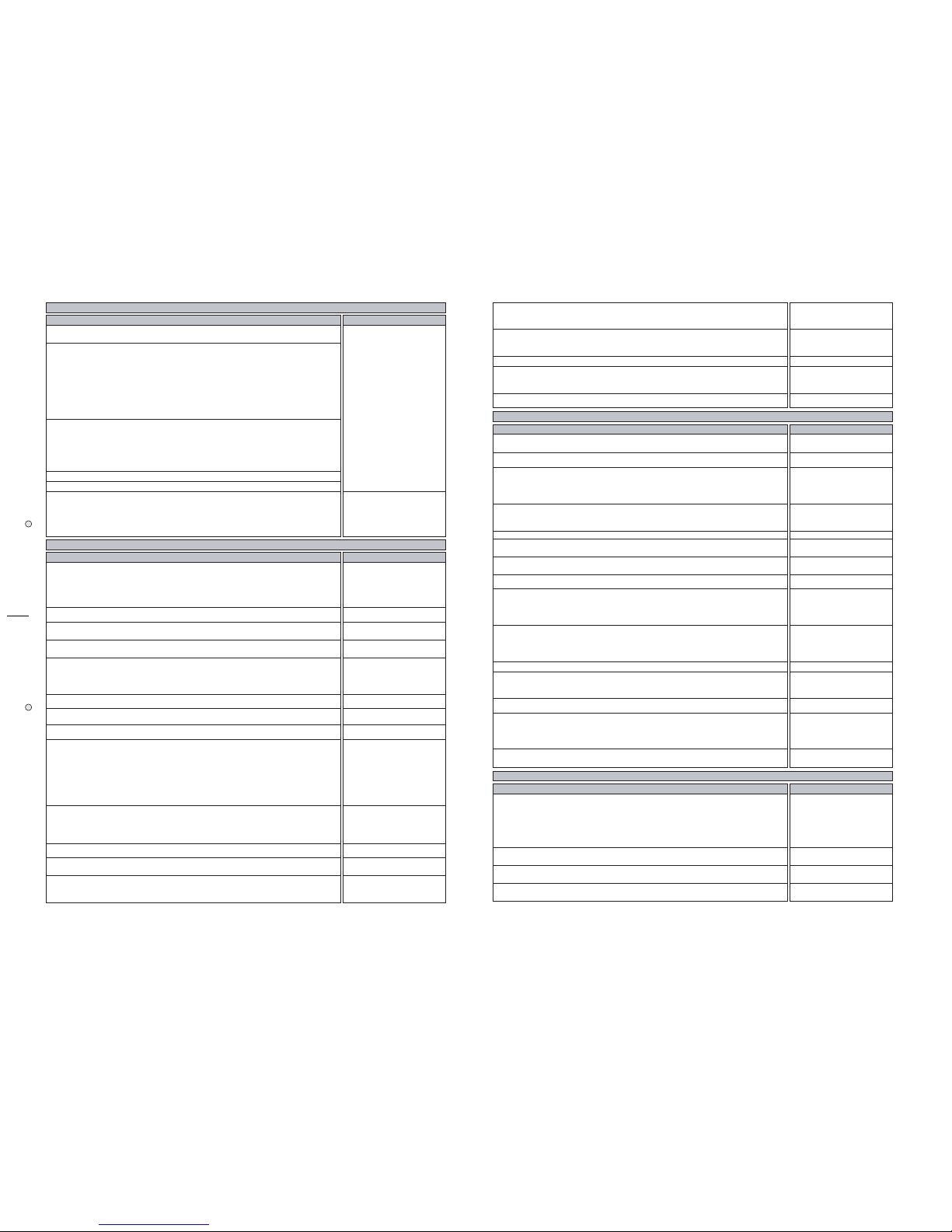
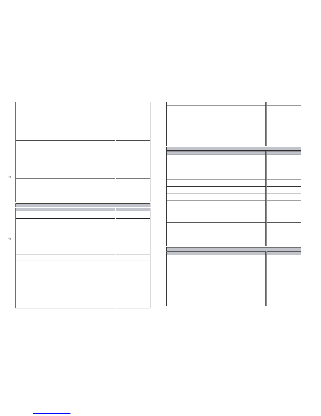
The procedures that follow must be executed subsequently in the order specified.
Before turn on the instrument check the jumpers setting on CPU & SOUND
GENERATOR BOARD corresponds at the model accordingly to the following table:
MODEL J4 J5 J3 J6 J2
RP100 GEM 1-2 1-2 1-2 1-2 1-2
RP100 BALDWIN 1-2 1-2 1-2 1-2 2-3
RP150 GEM 1-2 1-2 1-2 2-3 1-2
RP150 BALDWIN 1-2 1-2 1-2 2-3 2-3
RP90 GEM 1-2 1-2 2-3 1-2 1-2 ** v.2.00 or greater
RP90 BALDWIN 1-2 1-2 2-3 1-2 2-3 ** v.2.00 or greater
Remove the secondary fuses F1, F2, F3, located on POWER AMPLIFIER & SUPPLY
BOARD; turn on the instrument and verify the supply AC voltages:
(CN5) between pin1 and pin3 = 10±0,5Vac
(CN9) between pin1 and pin2 = 16±0,8Vac
(CN9) between pin1 and pin3 = 16±0,8Vac
(CN9) between pin2 and pin3 = 32±1,6Vac
Turn off the instrument, and put the fuses back on its holders.
Turn on the instrument and the appropriate welcome message appears on the display.
A few seconds later the led GRAND PIANO light.
Check the supply DC voltages on CPU & SOUND GENERATOR BOARD:
(CN8) between pin9 and pin7 = +5±0,25Vdc
(CN8) between pin1 and pin4 = +12±0,6Vdc
(CN8) between pin1 and pin5 = -12±0,6Vdc
|INTERNAL PRESET|
| GRAND PIANO |
RP100-150 AUTOTEST PROCEDURE
Operation Descriptions Display
The instrument starts in AUTOTEST mode turning on the instrument while pressing
down the "GRAND PIANO" button (pressing PRESET instead GRAND PIANO the
procedure starts from LCD display test).
NOTE: Each time you press the "GRAND PIANO" button the autotest procedure
proceeds to the next step.
| RP98 |
| AUTOTEST |
Set the default display contrast in the ±6 range by pressing the DATA + or - buttons.
|CONTRAST = # |
|
|
The instrument show the date, time and release version of the software loaded in
flash memory.
| mmm dd yyyy |
|hh:mm:ss V #.##|
The instrument asks if you want to update it, press GRAND PIANO to skip, the
appropriate procedure to update the software is explained further.
|EPROM to FLASH |
|push REC to prog|
The instrument performs the flash memory data checksum and display it in
hexadecimal value.
NOTE: the BT (boot) value must be 95C4 for ver.2.00, if it does not correspond you
can not update software thru serial port but only with Update Software Board.
|Wait * |
|Eprom Checksum |
|cks BT PR ALL|
|
#### #### ####
|
The instrument performs the RAM memory test showing the address checked.
|RAM MEMORY CHECK|
|
addr 23BFFF OK
|
The LCD display test shows two rows of sixteen dark spaces.
|❚ ❚ ❚ ❚ ❚ ❚ ❚ ❚ ❚ ❚ ❚ ❚ ❚ ❚ ❚|
|
❚ ❚ ❚ ❚ ❚ ❚ ❚ ❚ ❚ ❚ ❚ ❚ ❚ ❚ ❚
|
Check that all leds are lighting.
|--- LED TEST ---|
|
Are all leds on?
|
Check the VOLUMES ranges from 0 to 127.
Check all buttons (except GRAND PIANO) pressing their one at a time and checking
that corresponding led lights, pressing PAGE UP and DOWN buttons the display shows
"U" and "D", pressing DATA + and - buttons the display shows "+" and "-", pressing
BALANCE < and > buttons the display shows an "X" in 1 and 2 digits, pressing
TOUCH, STORE and REC/CONTROL buttons the display shows an "X" in 3, 4 and 5
digits respectively.
| |Button test |
| |Vol:0 12345 |
|U|Button test +|
|D|Vol:127 XXXXX-|
Check the SOFT and SUSTAIN pedals, pressing each one the value change from 0
(released) to 127 (pressed), for RP100 the DAMPER pedal operation is similar, for
RP150 the DAMPER pedal varying its value continuosly from 0 (released) to nearly
127 (pressed).
|Soft Sust Damp|
| 0 0 0|
Check the MIDI I/O connecting the MIDI OUT and MIDI IN sockets by a MIDI cable.
|TEST MIDI IN/OUT|
|
LOOP DETECTED OK
|
Check COMPUTER I/O shorting pin 3 and pin 5 on the COMPUTER socket, check with
the oscilloscope a 4Vpp (1Mhz) signal on pin 1, set volume to half stroke.
|TST COMPUTER I/O|
|LOOP DETECTED OK|
The instrument generates a 1KHz sinusoidal signal in both audio channels. VOLUME
fader controls the amplitude of signal and TRANSPOSE b and # buttons controls the
frequency from 10Hz to 2756Hz.
| SINUS. SWEEP |
|Freq. 1000 Hz|
| * REALPIANO * |
| RP100 |
| * BALDWIN * |
|PIANOVELLE RP100|
| * REALPIANO * |
| RP150 |
| * BALDWIN * |
|PIANOVELLE RP150|
| * REALPIANO * |
| RP90 |
| * BALDWIN * |
|PIANOVELLE RP90 |
RP100-150 INITIAL CHECK
Re-set the frequency at 1KHz and check HEADPHONES and AUX outputs with the
oscilloscope inserting a stereo jack in the left phones socket (speakers will go be
silent) and two mono jack in the AUX OUT sockets and set volume to its maximum.
Now verify the following level of signals:
Phones output without load = 17±1.7Vpp
AUX output = 1.35±0.14Vpp
Set the VOLUME to minimum.
Apply a sinusoidal signal of 0.730Vpp at 1KHz with a generator to the AUX IN left and
right sockets and verify the signal output:
AUX output = 1.35±0.07Vpp
Autotest is over, turn off the instrument.
|TEST END: SWITCH|
|
POWER TO RESTART
|
RP100-150 O.S. UPDATING PROCEDURE up to ver. 2.00 with Updating Software Board (751180)
Operation Descriptions Display
Start with the instrument in AUTOTEST mode as described above and press GRAND
PIANO 2 times until the display shows the software version loaded in flash memory.
| mmm dd yyyy |
|hh:mm:ss V #.##|
Press GRAND PIANO to skip this procedure.
|EPROM to FLASH |
|
push REC to prog
|
The instrument performs the flash memory data checksum and display it in
hexadecimal value.
|Wait * |
|Eprom Checksum |
|cks BT PR ALL|
|
#### #### ####
|
Compare the software version and checksum with the value imprinted onto the
EPROM, if one of these does not match, the system must be upgraded, proceed to the
next step.
Turn off the instrument.
Insert the EPROM BOARD (where the operating system is stored) in the CN3
connector located on CPU & SOUND GENERATOR BOARD.
Start with the instrument in AUTOTEST mode as described above and press GRAND
PIANO 3 times.
When the display shows this message press REC.
|EPROM to FLASH |
|p
ush REC to pro
g|
The instrument erases the previous data in flash memory. After which the instrument
displays the amount of memory programming and finally the operation successful. If
the programming fails check the EPROM BOARD connection and repeat this procedure
from start.
|EPROM to FLASH |
|erasing |
|EPROM to FLASH |
|prog
: 1024/1024K
|
The instrument performs the eprom memory data checksum and displays it in
hexadecimal value, compare this value with the value imprinted onto the EPROM: if it
matches the EPROM is good.
|Wait * |
|Eprom Checksum |
|cks BT PR ALL|
|
#### #### ####
|
Turn off the instrument and disconnect the EPROM BOARD.
Start with the instrument in AUTOTEST mode as described above and press GRAND
PIANO 2 times until the display show the new software version loaded in flash
memory.
| mmm dd yyyy |
|hh:mm:ss V #.##|
Press GRAND PIANO to skip this procedure.
|EPROM to FLASH |
|p
ush REC to pro
g|
The instrument performs the flash memory data checksum and displays it in
hexadecimal value, compare this value with the value imprinted onto the EPROM: if it
matches the procedure has been executed succesfully.
|Wait * |
|Eprom Checksum |
|cks BT PR ALL|
|
#### #### ####
|
The procedure proceed as described in AUTOTEST section, if you do not want to check
the rest of the instrument simply turn off it.
RP100-150 O.S. UPDATING PROCEDURE from Serial Port (COMPUTER) ver. 2.xx or greater
Operation Descriptions Display
NOTE: This procedure is valid only if the software version installed on the piano is the
2.00 or greater.
Some additional tips and advices are included in the Flashblaster Firmware Update
Disk. The disk containing the Fblaster program can also be downloaded by internet at
generalmusic web site (www.generalmusic.com) or required at
support@generalmusic.com
Connect the serial cable between the COMPUTER of the piano and the RS232 COM
port of the computer (PC-Ibm or compatible).
Insert the disk in the drive A (or whatever your 3.5" drive is assigned to), open the
contents of drive A and double click on the fblaster.exe file.
From the OPTIONS/SETTINGS menu, make sure that the TEST AND PROGRAM choice
is selected. This is very important.
Page 4
J J
J J
J 4
Turn on the piano, while holding down the REC button until the display shows:
|READY TO UPDATE |
| |
Click with the mouse on the GO! button or, from the ACTION menu, select EXECUTE
(ALT+A, E). The piano display appears as follows:
|TESTING... |
|n1/n2 PACKETS |
At the end of the test the following display appears:
| TEST OK |
| |
After a short time, the following display appears:
|ERASING... |
|
|
You are now erasing the old operating system from FLASH memory. When the system
is erased, the following display appears as your new operating system is installed into
Flash Memor
y
:
|UPDATING... |
|n1/n2 PACKETS |
When the entire update procedure is completed, the following display appears:
|UPDATE_OK:SWITCH|
|
POWER TO RESTART
|
The update has now been successfully completed. Turn off the power switch on the
piano, and turn it back on again to use your updated instrument.
RP100-150 Some Repairing Tips
Operation Descriptions Display
This message could be appear if an error occur on the communication channel.
Possible solutions:
1) inconsistent data received on MIDI or COMPUTER input socket, check the ratings of
the device connected to the piano.
2) if the error persist, try to replace Outputs Board first and CPU board second.
|MIDI SCI error |
| |
This message could be appear if an error occur on the communication channel.
Possible solutions:
1) verify all the connections between Keyboard Interface Board and the CPU board.
2) if the error persist, try to replace Keyboard Interface Board first and CPU board
second.
|VALIS SCI error |
| |
This message could be appear if an error occur on the communication between CPU
and DISP3 chips.
Possible solutions:
1) verify all the tracks, solders and components between CPU and DISP3 chips as
shown in schematics.
2) if the error persist, replace the CPU board and send back to generalmusic the failed
CPU board.
|Disp Failure |
| |
Operation Descriptions Display
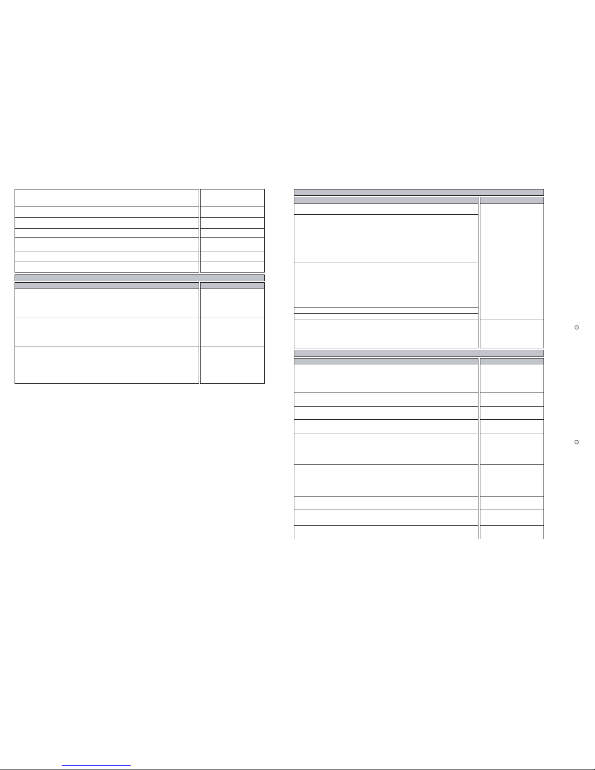
The procedures that follow must be executed subsequently in the order specified.
Before turn on the instrument check the jumpers setting on CPU & SOUND
GENERATOR BOARD corresponds at the model accordingly to the following table:
MODEL J4 J5 J3 J6 J2
RP200 GEM 1-2 1-2 1-2 1-2 1-2
RP200 BALDWIN 1-2 1-2 1-2 1-2 2-3
GRP300 GEM 1-2 1-2 1-2 2-3 1-2 ** v.2.00 or greater
GRP300 BALDWIN 1-2 1-2 1-2 2-3 2-3 ** v.2.00 or greater
Remove the secondary fuses F1, F2, F3, located on POWER AMPLIFIER & SUPPLY
BOARD; turn on the instrument and verify the supply AC voltages:
(CN6) between pin1 and pin2 = 27,5±1,5Vac
(CN6) between pin1 and pin3 = 27,5±1,5Vac
(CN6) between pin2 and pin3 = 55±3Vac
(CN12) between pin1 and pin2 = 16±0,8Vac
(CN12) between pin1 and pin3 = 16±0,8Vac
(CN12) between pin2 and pin3 = 32±1,6Vac
Turn off the instrument, and put the fuses back on its holders.
Turn on the instrument and the appropriate welcome message appears on the display.
A few seconds later the led GRAND PIANO light.
Check the supply DC voltages on CPU & SOUND GENERATOR BOARD:
(CN8) between pin9 and pin7 = +5±0,25Vdc
(CN8) between pin1 and pin4 = +12±0,6Vdc
(CN8) between pin1 and pin5 = -12±0,6Vdc
|INTERNAL PRESET|
| GRAND PIANO |
|GR.PIANO sel.:1|
RP200 AUTOTEST PROCEDURE
Operation Descriptions Display
The instrument starts in AUTOTEST mode turning on the instrument while pressing
down the "GRAND PIANO" button (pressing PRESET instead GRAND PIANO the
procedure starts from LCD display test).
NOTE: Each time you press the "GRAND PIANO" button the autotest procedure
proceeds to the next step.
| RP98 |
| AUTOTEST |
| |
Set the default display contrast in the ±6 range by pressing the DATA + or - buttons.
|CONTRAST = # |
| |
|
|
The instrument shows the date, time and release version of the software loaded in
flash memory.
| mmm dd yyyy |
|hh:mm:ss V #.##|
|
|
The instrument asks if you want to update it, press GRAND PIANO to skip, the
appropriate procedure to update the software is explained further.
|EPROM to FLASH |
|push REC to prog|
|
|
The instrument performs the flash memory data checksum and display it in
hexadecimal value.
NOTE: the BT (boot) value must be EAAB for ver.2.00, if it does not correspond you
can not update software thru serial port but only with Update Software Board see
more further.
|Wait * |
|Eprom Checksum |
| |
|cks BT PR ALL|
| #### #### ####|
|
|
The instrument performs the "LIBRARY" Rom memory data checksum and display it in
hexadecimal value.
|Wait * |
|Library Checksum|
| |
|Wait ok! |
|Checksum: A021|
|
|
The instrument performs the RAM memory test showing the address checked.
|RAM MEMORY CHECK|
|addr 23BFFF OK|
|
|
The LCD display test fades from light to dark and viceversa.
|❚ ❚ ❚ ❚ ❚ ❚ ❚ ❚ ❚ ❚ ❚ ❚ ❚ ❚ ❚|
|❚ ❚ ❚ ❚ ❚ ❚ ❚ ❚ ❚ ❚ ❚ ❚ ❚ ❚ ❚|
|
❚ ❚ ❚ ❚ ❚ ❚ ❚ ❚ ❚ ❚ ❚ ❚ ❚ ❚ ❚
|
Check that all leds are lighting.
|--- LED TEST ---|
|Are all leds on?|
|
|
RP200 INITIAL CHECK
| RP200 |
| REALPIANO |
| GEM |
| PIANOVELLE |
| RP200 |
| BALDWIN |
| GRP300 |
| REALPIANO |
| GEM |
| PIANOVELLE |
| GRP300 |
| BALDWIN |
Page 5
5
JJ
JJ
J
Check the VOLUMES ranges from 0 to 127.
Check all buttons (except GRAND PIANO) pressing their one at a time and checking
that corresponding led lights, pressing PAGE UP and DOWN buttons the display shows
"U" and "D", pressing DATA + and - buttons the display shows "+" and "-", pressing
MASTER EQ and DSP buttons the display shows an "X" in 1 and 2 digits, pressing UP,
LEFT, DOWN and RIGHT buttons the display shows an "X" in 3, 4, 5 and 6 digits
respectively.
| |Button test |
| |Vol:0 |
| 123456|
|U|Button test +|
|D|Vol:127 -|
| XXXXXX|
Check the SOFT and SUSTAIN pedals, pressing each one the value change from 0
(released) to 127 (pressed), the DAMPER pedal varying its value continuosly from 0
(released) to nearly 127 (pressed).
|Soft Sust Damp|
| 0 0 0|
| |
Check the MIDI I/O connecting the MIDI OUT and MIDI IN sockets by a MIDI cable.
|TEST MIDI IN/OUT|
|LOOP DETECTED OK|
|
|
Check COMPUTER I/O shorting pin 3 and pin 5 on the COMPUTER socket, check with
the oscilloscope a 4Vpp (1Mhz) signal on pin 1, set volume to half stroke.
|TST COMPUTER I/O|
|LOOP DETECTED OK|
|
|
The instrument generates a 1KHz sinusoidal signal in both audio channels reading
data from 104043 ROM. VOLUME controls the amplitude of signal and TRANSPOSE b
and # buttons controls the frequency from 10Hz to 2756Hz.
| SINUS. SWEEP |
|Freq. 1000 Hz|
| |
Re-set the frequency at 1KHz and check HEADPHONES and AUX outputs with the
oscilloscope inserting a stereo jack in the left phones socket (speakers will go be
silent) and two mono jack in the AUX OUT sockets and set volume to its maximum.
Now verify the following level of signals:
Phones output without load = 5,7±1.1Vpp
AUX output = 0,8±0,16Vpp
Set the VOLUME to minimum.
Apply a sinusoidal signal of 0.730Vpp at 1KHz with a generator to the AUX IN left and
right sockets and verify the signal output:
AUX output = 1,35±0.07Vpp
The instrument generates a tone signal in both audio channels reading data from
104023 ROM.
|TONE ON 104023 |
| |
|
|
Autotest is over, turn off the instrument.
|TEST END: SWITCH|
|POWER TO RESTART|
|
|
RP200 O.S. UPDATING PROCEDURE up to ver. 2.00 with Updating Software Board (751180)
Operation Descriptions Display
Start with the instrument in AUTOTEST mode as described above and press GRAND
PIANO 2 times until the display show the software version loaded in flash memory.
| mmm dd yyyy |
|hh:mm:ss V #.##|
|
|
Press GRAND PIANO to skip this procedure.
|EPROM to FLASH |
|push REC to prog|
|
|
The instrument performs the flash memory data checksum and displays it in
hexadecimal value.
|Wait * |
|Eprom Checksum |
| |
|cks BT PR ALL|
| #### #### ####|
|
|
Compare the software version and checksum with the value imprinted onto the
EPROM, if one of these does not match, the system must be upgraded, proceed to the
next step.
Turn off the instrument.
Insert the EPROM BOARD (where the operating system is stored) in the CN3
connector located on CPU & SOUND GENERATOR BOARD.
Start with the instrument in AUTOTEST mode as described above and press GRAND
PIANO 3 times.
When the display shows this message press REC.
|EPROM to FLASH |
|push REC to prog|
|
|
The instrument erases the previous data in flash memory. After which the instrument
displays the amount of memory programming and finally the operation successful. If
the programming fails check the EPROM BOARD connection and repeat this procedure
from start.
|EPROM to FLASH |
|erasing |
| |
|EPROM to FLASH |
|prog: 1024/1024K|
|
|
The instrument performs the eprom memory data checksum and display it in
hexadecimal value, compare this value with the value imprinted onto the EPROM: if it
matches the EPROM is good.
|Wait * |
|Eprom Checksum |
| |
|cks BT PR ALL|
| #### #### ####|
|
|
Turn off the instrument and disconnect the EPROM BOARD.
Start with the instrument in AUTOTEST mode as described above and press GRAND
PIANO 2 times until the display show the new software version loaded in flash
memory.
| mmm dd yyyy |
|hh:mm:ss V #.##|
| |
Press GRAND PIANO to skip this procedure.
|EPROM to FLASH |
|push REC to prog|
|
|
The instrument performs the flash memory data checksum and display it in
hexadecimal value, compare this value with the value imprinted onto the EPROM: if it
matches the procedure has been executed succesfully.
|Wait * |
|Eprom Checksum |
| |
|cks BT PR ALL|
| #### #### ####|
|
|
The procedure proceed as described in AUTOTEST section, if you do not want to check
the rest of the instrument simply turn off it.
RP200 O.S. UPDATING PROCEDURE from Serial Port (COMPUTER) ver. 2.xx or greater
Operation Descriptions Display
NOTE: This procedure is valid only if the software version installed on the piano is the
2.00 or greater.
Some additional tips and advices are included in the Flashblaster Firmware Update
Disk. The disk containing the Fblaster program can also be downloaded by internet at
generalmusic web site (www.generalmusic.com) or required at
support@generalmusic.com
Connect the serial cable between the COMPUTER of the piano and the RS232 COM
port of the computer (PC-Ibm or compatible).
Insert the disk in the drive A (or whatever your 3.5" drive is assigned to), open the
contents of drive A and double click on the fblaster.exe file.
From the OPTIONS/SETTINGS menu, make sure that the TEST AND PROGRAM choice
is selected. This is very important.
Turn on the piano, while holding down the REC button until the display shows:
|READY TO UPDATE |
| |
|
|
Click with the mouse on the GO! button or, from the ACTION menu, select EXECUTE
(ALT+A, E). The piano display appears as follows:
|TESTING... |
|n1/n2 PACKETS |
|
|
At the end of the test the following display appears:
| TEST OK |
| |
|
|
After a short time, the following display appears:
|ERASING... |
| |
|
|
You are now erasing the old operating system from FLASH memory. When the system
is erased, the following display appears as your new operating system is installed into
Flash Memory:
|UPDATING... |
|n1/n2 PACKETS |
| |
When the entire update procedure is completed, the following display appears:
|UPDATE_OK:SWITCH|
|POWER TO RESTART|
|
|
The update has now been successfully completed. Turn off the power switch on the
piano, and turn it back on again to use your updated instrument.
RP200 Some Repairing Tips
Operation Descriptions Display
This message could be appear if an error occur on the communication channel.
Possible solutions:
1) inconsistent data received on MIDI or COMPUTER input socket, check the ratings of
the device connected to the piano.
2) if the error persist, try to replace Outputs Board first and CPU board second.
|MIDI SCI error |
| |
| |
This message could be appear if an error occur on the communication channel.
Possible solutions:
1) verify all the connections between Keyboard Interface Board and the CPU board.
2) if the error persist, try to replace Keyboard Interface Board first and CPU board
second.
|VALIS SCI error |
| |
| |
This message could be appear if an error occur on the communication between CPU
and DISP3 chips.
Possible solutions:
1) verify all the tracks, solders and components between CPU and DISP3 chips as
shown in schematics.
2) if the error persist, replace the CPU board and send back to generalmusic the failed
CPU board.
|Disp Failure |
| |
| |
Page 6
J J
J J
J 6
Page 7

7
JJ
JJ
J
Page 8

J J
J J
J 8
Page 9

9
JJ
JJ
J
Page 10

J J
J J
J 10
Page 11

11
JJ
JJ
J
Page 12

J J
J J
J 12
Page 13

13
JJ
JJ
J
Page 14

J J
J J
J 14
Page 15

15
JJ
JJ
J
CPU & SOUND GENERATOR BOARD
PCB# 310603/1
Page 16

J J
J J
J 16
Page 17

17
JJ
JJ
J
Page 18

J J
J J
J 18
Spare Part List
Legend
EU = Specify European Version (230Vac)
US = Specify United States Version (115Vac)
R = Rosewood finish
B = Gloss Black finish
M = Mahogany finish
W = Gloss White finish
Baldwin = Baldwin version
Gem = Gem version
Code Description
RP100
Accessories
970243 Pianist’s Bench
970346 Portable Triple Pedal Switch
271243 Owner’s Manual (English,Italian,French,German)(Gem)
271266 Owner’s Manual (Dutch,Spanish,Danish)(Gem)
271236 Owner’s Manual (English, French, Spanish)(Baldwin)
130274 Mains Cable (EU)
130276 Mains Cable (US)
Consolette
970345 Consolette
660603 * Lower Cross-Bar Strengthening
660511 * Left Cabinet Support
660510 * Right Cabinet Support
651924 * Foot
261820 * Lower Cross-Bar
261819 * Left Leg
261818 * Right Leg
261092 * Upper Cross-Bar
150618 * Thumbscrew
120687 * Barrel Nut
120686 * Conical Screw
120685 * Threaded Rod
Cabinet
710472 Cabinet (Gem)
710471 Cabinet (Baldwin)
660606 Cover
660553 Keyboard Cross-Bar (Gem)
660505 Keyboard Cross-Bar (Baldwin)
660509 Flange for Left Side
660508 Flange for Right Side
653427 Left Side
653426 Right Side
652875 Speaker Grid
340075 Nylon Board Spacer
210017 2x10mm Adhesive Black Felt (specify mt)
210016 1x10mm Adhesive Black Felt (specify mt)
190015 Adhesive Rubber Foot
171657 Left Side Support
171656 Right Side Support
Music Stand
340913 Music Stand Stop
720566 Music Stand Assembly (Gem)
720564 Music Stand Assembly (Baldwin)
710466 * Wooden Music Stand Support (Gem)
710465 * Wooden Music Stand Support (Baldwin)
340914 * Plexiglass Music Stand
170612 * Music Stand Hinge
210017 * 2x10mm Adhesive Black Felt (specify mt)
Keyboard Cover
653431 Left Rack
653430 Right Rack
340811 Toothed Wheel
171651 Toothed Wheel Bar
120690 Toothed Wheel Lock
720565 Keyboard Cover Assembly
660599 * Bar Support Profile for Keyb. Cover
660598 * Top Handle Profile for Keyb. Cover
660597 * Bottom Handle Profile for Keyb. Cover
340922 * Plastic Sliding Cap for Handle
340912 * Plexiglass Keyboard Cover
340119 * Bush
190015 * Adhesive Rubber Foot
Mains Assembly
770839 Mains Cables Assembly
770834 Power Switch Cables Assembly
110320 * Power Switch
768197 Mains Filter Board (Pcb#310642)
230568 * 10mH 250Vac 1A AC Line EMI Coil “Siemens”
140010 * 3 Contacts P=10 Vert Terminal Block
020493 * 100n 250Vac MKP EMI Capacitor “Siemens”
010545 * 4n7 250V Ceramic Capacitor (Iec-Ul-Csa)
340916 Button for Power Switch
190133 Lateroid Insulator For Screw Block
171638 Mains Switch Support
140036 Screw Block (specify contacts)
110614 Mains Socket
020493 100n 250Vac MKP EMI Capacitor “Siemens”
Transformers
230136 Transformer 230Vac 130W (EU)
230137 Transformer 115Vac 130W (US)
Power Amplifier & Supply Board
730675 Power Amplifier & Supply Board (Pcb#310543)
340154 * TO3/TO218 Mica Washer
340079 * TO220 Mica Washer
340078 * TO220 Insulated Bush
141010 * 4 Contacts Vert Female Connector
140917 * 2 Contacts Vert Male Connector
140352 * 9 Contacts Hor Male Connector
140351 * 6 Contacts Hor Male Connector
140010 * 3 Contacts P=10 Vert Terminal Block
110119 * Fuse Clip 10A max (EU) (US)
100958 * TDA7265 Dual 25W Power Amplifier
100919 * MC33078 Dual LN Operational Amplifier
100059 * 7805 +5V 1A Voltage Regulator
100045 * 7812 +12V 1A Voltage Regulator
100043 * 7912 -12V 1A Voltage Regulator
090856 * J176 TO92 P-Channel J-Fet Transistor
090183 * BC550 TO92 LN Npn Transistor
080605 * KBL02 4A 200V Rectifier Diode Bridge
080156 * 1N4002 1A 100V Rectifier Diode
080103 * 1N4148 100mA 75V Signal Diode
110013 T1.25A Fuse 5x20mm (EU)
110003 T3.15A Fuse 5x20mm (EU)
110061 T3A Fuse 6.3x32mm (US)
110026 T1.25A Fuse 6.3x32mm (US)
Speakers Assembly
770835 Speakers Cables Assembly
261788 Speaker Box
220117 8ohm 5" Woofer Speaker
220115 8ohm 3" Tweeter Speaker
030171 4u7 63V 20% Axial Electrolytic Bipolar Capacitor
Phones Board
730516 Phones Board (Pcb# 310541)
230569 * FL5R200PNT EMI Coil For Signal
140351 * 6 Contacts Hor Male Connector
140217 * Jack Slim Horizontal S-F Socket
140207 * Jack Horizontal F Socket (with dual switch)
Keyboard Assembly
720558 Keyboard Assembly (TP21)
840762 * 20 Wires 25cm Length Flat Cable
840761 * 20 Wires 12.5cm Length Flat Cable
761173 * Keyboard Interface Board (Pcb#315024)
141018 ** 20 Contacts Vert Female Connector
141011 ** 6 Contacts Vert Female Connector
140918 ** 2 Contacts Hor Male Connector
100740 ** HD6433278 Cpu F=20MHz
100605 ** 74HC125 Quad 3-State Buffer
050493 ** 10Kx4 1/8w 5% Resistor Array
050492 ** 10Kx8 1/8w 5% Resistor Array
050414 ** 2K2x4 1/8w 5% Resistor Array
010725 ** 20MHz Ceramic Resonator With Capacitors
010662 ** 220p 10% 50V X8 Cap Array
010661 ** 47p 10% 50V X8 Cap Array
720560 * Keyboard Assembly (TP21)
840738 ** 4 Wires 5cm Length Flat Cable
810552 ** 39 Contacts L Board For Dynamic Keyb. (PCB#310531)
340764 *** 3 Dual Contacts Rubber Strip
340211 *** 12 Dual Contact Rubber Strip
141018 *** 20 Contacts Vert Female Connector
141010 *** 4 Contacts Vert Female Connector
080103 *** 1N4148 100mA 75V Signal Diode
810551 ** 49 Contacts R Board For Dynamic Keyb. (PCB#310530)
340212 *** 13 Dual Contact Rubber Strip
340211 *** 12 Dual Contact Rubber Strip
141018 *** 20 Contacts Vert Female Connector
141010 *** 4 Contacts Vert Female Connector
080103 *** 1N4148 100mA 75V Signal Diode
500075 ** Mechanical Keyboard (TP21)
160217 *** Sharp Key Return Spring
160216 *** Natural Key Return Spring
151236 *** Last C Key (TP21P)
151235 *** First A Key (TP21P)
151234 *** Sharp Key (TP21P)
151233 *** B Key (TP21P)
151232 *** A Key (TP21P)
151231 *** G Key (TP21P)
151230 *** F Key (TP21P)
151229 *** E Key (TP21P)
151228 *** D Key (TP21P)
151227 *** C Key (TP21P)
Controls Panel Assembly
820583 Controls Panel Assembly (Gem)
820582 Controls Panel Assembly (Baldwin)
810677 * Controls & Display Boards Assembly
730999 ** Controls Panel Board (Pcb#310609)
141018 *** 20 Contacts Vert Female Connector
140918 *** 2 Contacts Hor Male Connector
140529 *** Microswitch 12V 50mA 0.25mm
100606 *** 74HC138 1 Of 8 Decoder
090194 *** BC560 TO92 LN Pnp Transistor
080752 *** Led 3mm Wide Diffused Red
080724 *** Led 3mm 40deg High Eff Green
080103 *** 1N4148 100mA 75V Signal Diode
070551 *** 10K Linear 30mm Slider Potentiometer
730997 ** Display Board (Pcb#310638)
323069 *** 11.1X5mm Bumpon Rubber
141018 *** 20 Contacts Vert Female Connector
140918 *** 2 Contacts Hor Male Connector
140890 *** 4 Contacts Hor Male Single-Strip
080745 *** 2x16 Characters Lcd Display
660591 * Controls Panel (Gem)
660592 * Controls Panel (Baldwin)
653420 * <+ -> Rubber Pad
653419 * << >> Rubber Pad
653418 * <PLAY-REC> Rubber Pad
653417 * 2+4+8+8 Rubber Pad
653415 * 5+5+2 Rubber Pad
653413 * 4+1 Rubber Pad
651648 * Plexiglass Display Screen
340915 * LED Lens
340820 * Slider Knob
340523 * 6.5mm Spacer
340512 * Slider Potentiometer Guide
210258 * Slider Potentiometer Felt
210020 * 1.5x12mm Adhesive Red Felt (specify mt)
210017 * 2x10mm Adhesive Black Felt (specify mt)
CPU & Sound Generator Board
761171 CPU & Sound Generator Board (Pcb#310603)
560021 * GAL 16V8C-7 Programmed Disp3 Ram Read
560020 * GAL 16V8C-7 Programmed Disp3 Ram Write
141018 * 20 Contacts Vert Female Connector
141012 * 8 Contacts Vert Female Connector
141011 * 6 Contacts Vert Female Connector
141010 * 4 Contacts Vert Female Connector
140930 * 9 Contacts Hor Male Connector
140874 * Single In Line Vert Male Strip (specify contacts)
106003 * MAX709 Power Monitor With Reset
106001 * MC33078P SOIC Dual Low Noise Op. Amp.
105009 * DISP3 QFP Digital Sound Processor (Hitachi)
105006 * HD6413003F16 QFP Cpu
104042 * HM5118160J-5 16Mbit Dram Ta=50nS
104041 * 23C64000G SOP 64MBit Rom Wave98
104030 * AM29F400B-90EC TSOP 4Mbit Flash Memory Ta=90nS
104000 * HM628128LFP5 SOP 1Mbit Static Ram Ta=55nS
103012 * 74HC125D SOIC Quad Tri-State Buffer
103010 * 74HC04D SOIC Hex Inverter
103009 * 74HC02D SOIC Quad 2-In Nor Gate
103004 * AD1865R SOP 18bit D/A Converter
103002 * 74HC245DW SOIC Octal Bus Transceiver
103001 * 74HC08D SOIC Quad 2-Input And Gate
091001 * BC857 TO236 Smd Pnp Transistor
091000 * BC847 TO236 Smd Npn Transistor
081204 * 5.6V 0.5W Zener
081000 * PMLL4148 Smd 100mA 75V Signal Diode
055101 * 4K7 X4 1/16w 5% Smd Resistor Array
055100 * 100E X4 1/16w 5% Smd Resistor Array
011501 * 220pF x4 10% 100V NP0 Smd Capacitor Array
011500 * 47pF x4 10% 100V NP0 Smd Capacitor Array
010727 * 45.1584MHz Quartz Resonator
010704 * 16MHz Quartz Resonator
140877 * Jumper For Contacts Strip (p=2.54mm)
110282 * 3.6V 60mAh Nicd Battery
Outputs Assembly
730996 Outputs Assembly
730995 * Outputs Board (Pcb#310608)
230569 ** FL5R200PNT EMI Coil For Signal
230527 ** BL02RN2-R62 EMI Coil For Signal
141012 ** 8 Contacts Vert Female Connector
141010 ** 4 Contacts Vert Female Connector
140918 ** 2 Contacts Hor Male Connector
140908 ** 6 Contacts Vert Male Small Connector
140247 ** 8 Poles Mini Din Female Socket
140217 ** Jack Slim Horizontal S-F Socket
140216 ** 6 Poles Din Horizontal Female Socket
140212 ** 5 Poles Din Horizontal Female Socket
120857 ** Vertical Male Faston 6.3mm
100734 ** MAX202E RS232 Drivers/Receiver
100602 ** 74HC04 Hex Inverter
100035 ** 6N138 Optocoupler
090194 ** BC560 TO92 LN Pnp Transistor
090183 ** BC550 TO92 LN Npn Transistor
080103 ** 1N4148 100mA 75V Signal Diode
653440 * Outputs Panel
210018 * 1x5mm Adhesive Red Felt (specify mt)
171329 * Support for Outputs Panel
Wiring Connections
841174 20 Wires 20cm Length Flat Cable (3 Connectors)
841173 6 Wires 7.5cm Length Crimp Terminal Cable
841172 9 Wires 15cm Length Crimp Terminal Cable
841043 2 Wires 35cm Length Crimp Terminal Cable
841038 8 Wires 25cm Length Flat Cable
841036 6 Wires 45cm Length Flat Cable
840844 2 Wires 7.5cm Length Crimp Terminal Cable
840842 4 Wires 15cm Length Flat Cable
840768 4 Wires 10cm Length Flat Cable
840765 2 Wires 20cm Length Crimp Terminal Cable
RP150
Accessories
970319 Pianist’s Bench (M)
970297 Pianist’s Bench (B)
970296 Pianist’s Bench (R)
340116 Adhesive Clamp For Pedals Cable
271276 Owner’s Manual (English,French,Spanish)(Baldwin)
271259 Owner’s Manual (English,Italian,French,German)(Gem)
271267 Owner’s Manual (Dutch,Spanish,Danish)(Gem)
130274 Mains Cable (EU)
130276 Mains Cable (US)
Consolette
830746 Legs & Pedals Assembly (M)
830745 Legs & Pedals Assembly (B)
830744 Legs & Pedals Assembly (R)
710504 * Pedals Cross-bar Assembly (M)
710503 * Pedals Cross-bar Assembly (B)
710502 * Pedals Cross-bar Assembly (R)
720561 ** Triple Brassed Pedals Assembly
070556 *** 20K 90deg stroke potentiometer
510258 ** Pedal Wooden Parts (M)
510257 ** Pedal Wooden Parts (B)
510256 ** Pedal Wooden Parts (R)
261965 *** 20x20x70mm Deal Fillet
261946 *** Rear Cross-Bar for Pedals
261866 *** 20x20x200mm Deal Fillet
261812 *** Support for Pedalboard
261952 *** Top Cross-Bar for Pedals (M)
261831 *** Top Cross-Bar for Pedals (B)
261806 *** Top Cross-Bar for Pedals (R)
261953 *** Front Cross-Bar for Pedals (M)
261830 *** Front Cross-Bar for Pedals (B)
261807 *** Front Cross-Bar for Pedals (R)
261811 ** Pedalboard
210021 ** 1x15mm Adhesive Red Felt (specify mt)
171585 ** Angular Fixing for Pedals Cross-bar
660407 * Speaker Box Fixing
261943 * Lower Panel (M)
261940 * Lower Panel (B)
261937 * Lower Panel (R)
261962 * Left Foot (M)
261828 * Left Foot (B)
261809 * Left Foot (R)
261961 * Right Foot (M)
261829 * Right Foot (B)
261808 * Right Foot (R)
261951 * Left Side (M)
261833 * Left Side (B)
261803 * Left Side (R)
261950 * Right Side (M)
261834 * Right Side (B)
261802 * Right Side (R)
171702 * Right Cabinet Support
171701 * Left Cabinet Support
Cabinet
Top Cabinet Assembly
710534 Top Cabinet Assembly (M)
710533 Top Cabinet Assembly (B)
710532 Top Cabinet Assembly (R)
510268 * Top Cover Assembly (M)
510267 * Top Cover Assembly (B)
510266 * Top Cover Assembly (R)
261866 ** 20x20x200mm Deal Fillet
261958 ** Cabinet Cover (M)
261837 ** Cabinet Cover (B)
261798 ** Cabinet Cover (R)
340090 * Music Stand Bush
Front Panel Assembly
710544 Front Panel Assembly (Baldwin) (M)
710543 Front Panel Assembly (Baldwin) (B)
710542 Front Panel Assembly (Baldwin) (R)
710523 Front Panel Assembly (Gem)(M)
710522 Front Panel Assembly (Gem)(B)
710521 Front Panel Assembly (Gem)(R)
710553 * Front Panel (Baldwin)(M)
710552 * Front Panel (Baldwin)(B)
710551 * Front Panel (Baldwin)(R)
710501 * Front Panel (Gem)(M)
710500 * Front Panel (Gem)(B)
710499 * Front Panel (Gem)(R)
324405 * Hinge
261944 * Music Stand (M)
261941 * Music Stand (B)
261938 * Music Stand (R)
219066 * Adhesive Black Felt for Music Stand
210016 * 1x10mm Adhesive Black Felt (specify mt)
171679 * Front Panel Angular Reinforcement
171669 * Left Fixing Bar
171664 * Right Fixing Bar
Keyboard Cover Assembly
710520 Keyboard Cover Assembly (M)
710519 Keyboard Cover Assembly (B)
710518 Keyboard Cover Assembly (R)
660612 * Front Keyboard Cover Handle
340922 * Plastic Sliding Cap for Handle
340811 * Toothed Wheel
340119 * Bush
261949 * Keyboard Cover (M)
261948 * Keyboard Cover (B)
261947 * Keyboard Cover (R)
210017 * 2x10mm Adhesive Black Felt (specify mt)
210016 * 1x10mm Adhesive Black Felt (specify mt)
171665 * Keyboard Cover Bar Support
171335 * Toothed Wheel Bar
120690 * Toothed Wheel Lock
Cabinet Assembly
710557 Cabinet (Baldwin) (M)
710556 Cabinet (Baldwin) (B)
710555 Cabinet (Baldwin) (R)
710513 Cabinet (Gem) (M)
710512 Cabinet (Gem) (B)
710511 Cabinet (Gem) (R)
660609 * Speaker Socket Support
660410 * Speakers Protection Grid
660405 * Heatsink Grid
510264 * Cabinet Wooden Parts (Baldwin) (M)
510262 * Cabinet Wooden Parts (Baldwin) (B)
510260 * Cabinet Wooden Parts (Baldwin) (R)
510263 * Cabinet Wooden Parts (Gem) (M)
510261 * Cabinet Wooden Parts (Gem) (B)
510259 * Cabinet Wooden Parts (Gem) (R)
710540 ** Keyboard Cross-Bar (Baldwin) (M)
710480 ** Keyboard Cross-Bar (Baldwin) (B)
710469 ** Keyboard Cross-Bar (Baldwin) (R)
710497 ** Keyboard Cross-Bar (Gem) (M)
710481 ** Keyboard Cross-Bar (Gem) (B)
710470 ** Keyboard Cross-Bar (Gem) (R)
Page 19

19
JJ
JJ
J
710541 ** Rear Panel (Baldwin) (M)
710474 ** Rear Panel (Baldwin) (B)
710467 ** Rear Panel (Baldwin) (R)
710498 ** Rear Panel (Gem) (M)
710475 ** Rear Panel (Gem) (B)
710468 ** Rear Panel (Gem) (R)
261840 ** Bottom Support Panel
261954 ** Cabinet Right Side (M)
261841 ** Cabinet Right Side (B)
261791 ** Cabinet Right Side (R)
261955 ** Cabinet Left Side (M)
261842 ** Cabinet Left Side (B)
261790 ** Cabinet Left Side (R)
340904 * Toothed Bar
323012 * Plastic Pivot
171331 * Left Cover Clamp
171330 * Right Cover Clamp
150474 * Plug For Unused Hole
653433 Left Plastic Lateral
653432 Right Plastic Lateral
340075 Nylon Board Spacer
210217 Black Sealer (specify mt)
210216 Adhesive Rubber Foam 20x5mm (Specify mt)
210054 1x5mm Adhesive Spik (specify mt)
Mains Assembly
770860 Mains Cables Assembly
110320 * Power Switch
340916 Switch Button
171638 Mains Switch Support
110614 Mains Socket
768197 Mains Filter Board (Pcb#310642)
230568 * 10mH 250Vac 1A AC Line EMI Coil “Siemens”
140010 * 3 Contacts P=10 Vert Terminal Block
020493 * 100n 250Vac MKP EMI Capacitor “Siemens”
010545 * 4n7 250V Ceramic Capacitor (Iec-Ul-Csa)
Transformer
230137 Transformer 115Vac 130W (US)
230136 Transformer 230Vac 130W (EU)
Power Amplifier & Supply Board
730675 Power Amplifier & Supply Board (Pcb#310543)
340154 * TO3/TO218 Mica Washer
340079 * TO220 Mica Washer
340078 * TO220 Insulated Bush
141010 * 4 Contacts Vert Female Connector
140917 * 2 Contacts Vert Male Connector
140352 * 9 Contacts Hor Male Connector
140351 * 6 Contacts Hor Male Connector
140010 * 3 Contacts P=10 Vert Terminal Block
110119 * Fuse Clip 10A max (EU) (US)
100958 * TDA7265 Dual 25W Power Amplifier
100919 * MC33078 Dual LN Operational Amplifier
100059 * 7805 +5V 1A Voltage Regulator
100045 * 7812 +12V 1A Voltage Regulator
100043 * 7912 -12V 1A Voltage Regulator
090856 * J176 TO92 P-Channel J-Fet Transistor
090183 * BC550 TO92 LN Npn Transistor
080605 * KBL02 4A 200V Rectifier Diode Bridge
080156 * 1N4002 1A 100V Rectifier Diode
080103 * 1N4148 100mA 75V Signal Diode
110013 T1.25A Fuse 5x20mm (EU)
110003 T3.15A Fuse 5x20mm (EU)
110061 T3A Fuse 6.3x32mm (US)
110026 T1.25A Fuse 6.3x32mm (US)
Speakers Assembly
770859 Speaker Cables Assembly
220120 6" Full-range 8E Speaker
220119 3" Full-range 8E Speaker
340928 Plastic Speaker Box
210242 Filler for Speaker Box (Specify m²)
171699 3" Speaker Support
Keyboard Assembly
720568 Keyboard Assembly (TP10MDS)
840762 * 20 Wires 25cm Length Flat Cable
840761 * 20 Wires 12.5cm Length Flat Cable
761173 * Keyboard Interface Board (Pcb#315024)
141018 ** 20 Contacts Vert Female Connector
141011 ** 6 Contacts Vert Female Connector
140918 ** 2 Contacts Hor Male Connector
100740 ** HD6433278 Cpu F=20MHz
100605 ** 74HC125 Quad 3-State Buffer
050493 ** 10Kx4 1/8w 5% Resistor Array
050492 ** 10Kx8 1/8w 5% Resistor Array
050414 ** 2K2x4 1/8w 5% Resistor Array
010725 ** 20MHz Ceramic Resonator With Capacitors
010662 ** 220p 10% 50V X8 Cap Array
010661 ** 47p 10% 50V X8 Cap Array
720559 * Keyboard Assembly (TP10MDS)
840738 ** 4 Wires 5cm Length Flat Cable
810552 ** 39 Contacts L Board For Dynamic Keyb. (PCB#310531)
340764 *** 3 Dual Contacts Rubber Strip
340211 *** 12 Dual Contact Rubber Strip
141018 *** 20 Contacts Vert Female Connector
141010 *** 4 Contacts Vert Female Connector
080103 *** 1N4148 100mA 75V Signal Diode
810551 ** 49 Contacts R Board For Dynamic Keyb. (PCB#310530)
340212 *** 13 Dual Contact Rubber Strip
340211 *** 12 Dual Contact Rubber Strip
141018 *** 20 Contacts Vert Female Connector
141010 *** 4 Contacts Vert Female Connector
080103 *** 1N4148 100mA 75V Signal Diode
500074 ** Mechanicals Parts (TP10MDS)
151226 *** Last C Key (TP10MDS)
151225 *** First A Key (TP10MDS)
151224 *** Sharp Key (TP10MDS)
151223 *** B Key (TP10MDS)
151222 *** A Key (TP10MDS)
151221 *** G Key (TP10MDS)
151220 *** F Key (TP10MDS)
151219 *** E Key (TP10MDS)
151218 *** D Key (TP10MDS)
151217 *** C Key (TP10MDS)
340092 * 5mm Board Spacer
210017 * 2x10mm Adhesive Black Felt (specify mt)
Controls Panel Assembly
820592 Controls Panel Assembly (Baldwin)
820590 Controls Panel Assembly (Gem)
810677 * Controls & Display Boards Assembly
730999 ** Controls Panel Board (Pcb#310609)
141018 *** 20 Contacts Vert Female Connector
140918 *** 2 Contacts Hor Male Connector
140529 *** Microswitch 12V 50mA 0.25mm
100606 *** 74HC138 1 Of 8 Decoder
090194 *** BC560 TO92 LN Pnp Transistor
080752 *** Led 3mm Wide Diffused Red
080724 *** Led 3mm 40deg High Eff Green
080103 *** 1N4148 100mA 75V Signal Diode
070551 *** 10K Linear 30mm Slider Potentiometer
730997 ** Display Board (Pcb#310638)
323069 *** 11.1X5mm Bumpon Rubber
141018 *** 20 Contacts Vert Female Connector
140918 *** 2 Contacts Hor Male Connector
140890 *** 4 Contacts Hor Male Single-Strip
080745 *** 2x16 Characters Lcd Display
660635 * Control Panel (Baldwin)
660610 * Control Panel (Gem)
653420 * <+ -> Rubber Pad
653419 * << >> Rubber Pad
653418 * <PLAY-REC> Rubber Pad
653417 * 2+4+8+8 Rubber Pad
653415 * 5+5+2 Rubber Pad
653413 * 4+1 Rubber Pad
651648 * Plexiglass Display Screen
651563 * Cloth For Panel Slits
340915 * LED Lens
340820 * Slider Knob
340523 * 6.5mm Spacer
340512 * Slider Potentiometer Guide
210258 * Slider Potentiometer Felt
210020 * 1.5x12mm Adhesive Red Felt (specify mt)
210017 * 2x10mm Adhesive Black Felt (specify mt)
171661 * Front Support
CPU & Sound Generator Board
761171 CPU & Sound Generator Board (Pcb#310603)
560021 * GAL 16V8C-7 <DISP3 RAM READ
560020 * GAL 16V8C-7 <DISP3 RAM WRITE
141018 * 20 Contacts Vert Female Connector
141012 * 8 Contacts Vert Female Connector
141011 * 6 Contacts Vert Female Connector
141010 * 4 Contacts Vert Female Connector
140930 * 9 Contacts Hor Male Connector
140874 * Single In Line Vert Male Strip (specify contacts)
106003 * MAX709 Power Monitor With Reset
106001 * MC33078P SOIC Dual Low Noise Op. Amp.
105009 * DISP3 QFP Digital Sound Processor (Hitachi)
105006 * HD6413003F16 QFP Cpu
104042 * HM5118160J-5 16Mbit Dram Ta=50nS
104041 * 23C64000G SOP 64MBit Rom Wave98
104030 * AM29F400B-90EC TSOP 4Mbit Flash Memory Ta=90nS
104000 * HM628128LFP5 SOP 1Mbit Static Ram Ta=55nS
103012 * 74HC125D SOIC Quad Tri-State Buffer
103010 * 74HC04D SOIC Hex Inverter
103009 * 74HC02D SOIC Quad 2-In Nor Gate
103004 * AD1865R SOP 18bit D/A Converter
103002 * 74HC245DW SOIC Octal Bus Transceiver
103001 * 74HC08D SOIC Quad 2-Input And Gate
091001 * BC857 TO236 Smd Pnp Transistor
091000 * BC847 TO236 Smd Npn Transistor
081204 * 5.6V 0.5W Zener
081000 * PMLL4148 Smd 100mA 75V Signal Diode
055101 * 4K7 X4 1/16w 5% Smd Resistor Array
055100 * 100E X4 1/16w 5% Smd Resistor Array
011501 * 220pF x4 10% 100V NP0 Smd Capacitor Array
011500 * 47pF x4 10% 100V NP0 Smd Capacitor Array
010727 * 45.1584MHz Quartz Resonator
010704 * 16MHz Quartz Resonator
140877 * Jumper For Contacts Strip (p=2.54mm)
110282 * 3.6V 60mAh Nicd Battery
HF Crossover Filter Board
731019 HF Crossover Filter Board (Pcb#310654)
140323 * 6 Contacts Vert Male Connector
060253 * 10E 5W 10% Wire Resistor
030348 * 47u 100V 20% Axial Electrolytic Bipolar Capacitor
Outputs Assembly
730996 Outputs Assembly
730995 * Outputs Board (Pcb#310608)
230569 ** FL5R200PNT EMI Coil For Signal
230527 ** BL02RN2-R62 EMI Coil For Signal
141012 ** 8 Contacts Vert Female Connector
141010 ** 4 Contacts Vert Female Connector
140918 ** 2 Contacts Hor Male Connector
140908 ** 6 Contacts Vert Male Small Connector
140247 ** 8 Poles Mini Din Female Socket
140217 ** Jack Slim Horizontal S-F Socket
140216 ** 6 Poles Din Horizontal Female Socket
140212 ** 5 Poles Din Horizontal Female Socket
100734 ** MAX202E RS232 Drivers/Receiver
100602 ** 74HC04 Hex Inverter
100035 ** 6N138 Optocoupler
090194 ** BC560 TO92 LN Pnp Transistor
090183 ** BC550 TO92 LN Npn Transistor
080103 ** 1N4148 100mA 75V Signal Diode
653440 * Output Panel Box
210018 * 1x5mm Adhesive Red Felt (specify mt)
171329 * Support for Output Panel Box
Phones Assembly
730674 Phones Assembly
730516 * Phones Board (pcb# 310541)
230569 ** FL5R200PNT EMI Coil For Signal
140351 ** 6 Contacts Hor Male Connector
140217 ** Jack Slim Horizontal S-F Socket
140207 ** Jack Horizontal F Socket (with dual switch)
652854 * Phones Board Support
210017 * 2x10mm Adhesive Black Felt (specify mt)
Wiring Connections
841206 4 Wires 20cm Length Flat Cable
841205 9 Wires 7.5cm Length Crimp Terminal Cable
841176 20 Wires 48cm Length Flat Cable (3 Connectors)
841173 6 Wires 7.5cm Length Crimp Terminal Cable
841063 6 Wires 55cm Length Flat Cable
841043 2 Wires 35cm Length Crimp Terminal Cable
841041 8 Wires 12.5cm Length Flat Cable
841010 2 Wires 50cm Length Crimp Terminal Cable
840844 2 Wires 7.5cm Length Crimp Terminal Cable
840799 4 Wires 7.5cm Length Flat Cable
RP200
Accessories
970319 Pianist’s Bench (M)
970297 Pianist’s Bench (B)
970296 Pianist’s Bench (R)
970298 Pianist’s Bench (W)
340116 Adhesive Clamp For Pedals Cable
271237 Owner’s Manual (English, Italian, French, German)(Gem)
271268 Owner’s Manual (Dutch,Spanish,Danish)(Gem)
271258 Owner’s Manual (English, French, Spanish)(Baldwin)
130274 Mains Cable (EU)
130276 Mains Cable (US)
Consolette
830743 Legs & Pedals Assembly (M)
830742 Legs & Pedals Assembly (B)
830741 Legs & Pedals Assembly (R)
830752 Legs & Pedals Assembly (W)
710530 * Cloth Panel Assembly
340159 ** 3M Dual Lock Fastening (Specify mt)
261805 ** Cloth Panel
210074 ** Speaker Cloth
710517 * Speaker Box Assembly (M)
710516 * Speaker Box Assembly (B)
710515 * Speaker Box Assembly (R)
710549 * Speaker Box Assembly (W)
770727 ** Speaker Cables Assembly
510265 ** Speaker Box (M)
510243 ** Speaker Box (B)
510245 ** Speaker Box (R)
510244 ** Speaker Box (W)
261963 *** Speaker Box Rear Panel (M)
261832 *** Speaker Box Rear Panel (B)
261804 *** Speaker Box Rear Panel (R)
261848 *** Speaker Box Rear Panel (W)
261823 *** Speaker Box Lower Panel
261822 *** Speaker Box Upper Panel
261821 *** Speaker Box Divider Panel
261794 *** Speaker Box Front Panel
261793 *** Speaker Box Side Panel
340159 ** 3M Dual Lock Fastening (Specify mt)
220118 ** 8ohm 8" Woofer Speaker
210242 ** Filler for Speaker Box (Specify m²)
710504 * Pedals Cross-bar Assembly (M)
710503 * Pedals Cross-bar Assembly (B)
710502 * Pedals Cross-bar Assembly (R)
710550 * Pedals Cross-bar Assembly (W)
720561 ** Triple Brassed Pedals Assembly
510258 ** Pedal Wooden Parts (M)
510257 ** Pedal Wooden Parts (B)
510256 ** Pedal Wooden Parts (R)
510270 ** Pedal Wooden Parts (W)
261965 *** 20x20x70mm Deal Fillet
261946 *** Rear Cross-Bar for Pedals
261866 *** 20x20x200mm Deal Fillet
261952 *** Top Cross-Bar for Pedals (M)
261831 *** Top Cross-Bar for Pedals (B)
261806 *** Top Cross-Bar for Pedals (R)
261847 *** Top Cross-Bar for Pedals (W)
261953 *** Front Cross-Bar for Pedals (M)
261830 *** Front Cross-Bar for Pedals (B)
261807 *** Front Cross-Bar for Pedals (R)
261846 *** Front Cross-Bar for Pedals (W)
261812 *** Support for Pedalboard
261811 ** Pedalboard
210021 ** 1x15mm Adhesive Red Felt (specify mt)
171585 ** Angular Fixing for Pedals Cross-bar
120681 ** Sleeve for Internal Cheek Block
660407 * Speaker Box Fixing
261950 * Right Side (M)
261834 * Right Side (B)
261802 * Right Side (R)
261850 * Right Side (W)
261951 * Left Side (M)
261833 * Left Side (B)
261803 * Left Side (R)
261849 * Left Side (W)
261961 * Right Foot (M)
261829 * Right Foot (B)
261808 * Right Foot (R)
261845 * Right Foot (W)
261962 * Left Foot (M)
261828 * Left Foot (B)
261809 * Left Foot (R)
261844 * Left Foot (W)
171702 * Right Cabinet Support
171701 * Left Cabinet Support
Cabinet
Top Cabinet Assembly
710534 Top Cabinet Assembly (M)
710533 Top Cabinet Assembly (B)
710532 Top Cabinet Assembly (R)
710546 Top Cabinet Assembly (W)
510268 * Top Cover Assembly (M)
510267 * Top Cover Assembly (B)
510266 * Top Cover Assembly (R)
510269 * Top Cover Assembly (W)
261866 ** 20x20x200mm Deal Fillet
261958 ** Cabinet Cover (M)
261837 ** Cabinet Cover (B)
261798 ** Cabinet Cover (R)
261853 ** Cabinet Cover (W)
340090 * Music Stand Bush
Front Panel Assembly
710528 Front Panel Assembly (Gem)(M)
710526 Front Panel Assembly (Gem)(B)
710524 Front Panel Assembly (Gem)(R)
710529 Front Panel Assembly (Baldwin)(M)
710527 Front Panel Assembly (Baldwin)(B)
710525 Front Panel Assembly (Baldwin)(R)
710545 Front Panel Assembly (Baldwin)(W)
710536 * Front Finishing Fillet (Gem) (M)
710535 * Front Finishing Fillet (Gem) (B)
710531 * Front Finishing Fillet (Gem) (R)
710539 * Front Finishing Fillet (Baldwin) (M)
710538 * Front Finishing Fillet (Baldwin) (B)
710537 * Front Finishing Fillet (Baldwin) (R)
710548 * Front Finishing Fillet (Baldwin) (W)
340919 * Music Stand
261959 * Centre Front Panel (M)
261839 * Centre Front Panel (B)
261795 * Centre Front Panel (R)
261855 * Centre Front Panel (W)
261796 * Wooden Front Panel
210016 * 1x10mm Adhesive Black Felt (specify mt)
171677 * Left Speaker Grid
171669 * Left Fixing Bar
171667 * Right Speaker Grid
171664 * Right Fixing Bar
Keyboard Cover Assembly
710520 Keyboard Cover Assembly (M)
710519 Keyboard Cover Assembly (B)
710518 Keyboard Cover Assembly (R)
710547 Keyboard Cover Assembly (W)
660612 * Front Keyboard Cover Handle
340922 * Plastic Sliding Cap for Handle
340811 * Toothed Wheel
340119 * Bush
261949 * Keyboard Cover (M)
261948 * Keyboard Cover (B)
261947 * Keyboard Cover (R)
261978 * Keyboard Cover (W)
210017 * 2x10mm Adhesive Black Felt (specify mt)
210016 * 1x10mm Adhesive Black Felt (specify mt)
171665 * Keyboard Cover Bar Support
171335 * Toothed Wheel Bar
120690 * Toothed Wheel Lock
Cabinet Assembly
710509 Cabinet (Gem) (M)
710507 Cabinet (Gem) (B)
710505 Cabinet (Gem) (R)
710510 Cabinet (Baldwin) (M)
710508 Cabinet (Baldwin) (B)
710506 Cabinet (Baldwin) (R)
710554 Cabinet (Baldwin) (W)
660609 * Speaker Socket Support
660405 * Heatsink Grid
510263 * Cabinet Wooden Parts (Gem) (M)
510261 * Cabinet Wooden Parts (Gem) (B)
510259 * Cabinet Wooden Parts (Gem) (R)
510264 * Cabinet Wooden Parts (Baldwin) (M)
510262 * Cabinet Wooden Parts (Baldwin) (B)
510260 * Cabinet Wooden Parts (Baldwin) (R)
510271 * Cabinet Wooden Parts (Baldwin) (W)
710497 ** Keyboard Cross-Bar (Gem) (M)
710481 ** Keyboard Cross-Bar (Gem) (B)
710470 ** Keyboard Cross-Bar (Gem) (R)
710540 ** Keyboard Cross-Bar (Baldwin) (M)
710480 ** Keyboard Cross-Bar (Baldwin) (B)
710469 ** Keyboard Cross-Bar (Baldwin) (R)
710476 ** Keyboard Cross-Bar (Baldwin) (W)
710498 ** Rear Panel (Gem) (M)
710475 ** Rear Panel (Gem) (B)
710468 ** Rear Panel (Gem) (R)
710541 ** Rear Panel (Baldwin) (M)
710474 ** Rear Panel (Baldwin) (B)
Page 20

J J
J J
J 20
710467 ** Rear Panel (Baldwin) (R)
710478 ** Rear Panel (Baldwin) (W)
261955 ** Cabinet Left Side (M)
261842 ** Cabinet Left Side (B)
261790 ** Cabinet Left Side (R)
261858 ** Cabinet Left Side (W)
261954 ** Cabinet Right Side (M)
261841 ** Cabinet Right Side (B)
261791 ** Cabinet Right Side (R)
261857 ** Cabinet Right Side (W)
261840 ** Bottom Support Panel
340904 * Toothed Bar
323012 * Plastic Pivot
261813 * Midrange Cabinet Support
171331 * Left Cover Clamp
171330 * Right Cover Clamp
653433 Left Plastic Lateral
653432 Right Plastic Lateral
340075 Nylon Board Spacer
Mains Assembly
110614 Mains Socket
770844 Power Switch & Cables Assembly
110320 * Power Switch
340916 Button for Power Switch
171638 Mains Switch Support
770839 Mains Cables Assembly
768198 Mains Filter Board (Pcb#310643)
230565 * 2.5mH 250V 3A AC Line Filter
140010 * 3 Contacts P=10 Vert Terminal Block
020493 * 100n 250Vac MKP EMI Capacitor “Siemens”
010545 * 4n7 250V Ceramic Capacitor (Iec-Ul-Csa)
Transformer Assembly
730453 * Transformer Assembly 230Vac (EU)
730470 * Transformer Assembly 115Vac (US)
340329 ** Rubber Bush
230130 ** Transformer 230Vac 220W (EU)
230131 ** Transformer 115Vac 220W (US)
190133 ** Lateroid Insulator For Screw Block
140036 ** Screw Block (specify contacts)
Power Amplifier & Supply Board
731004 Power Amplifier & Supply Board (Pcb#310604)
340154 * TO3/TO218 Mica Washer
340079 * TO220 Mica Washer
340078 * TO220 Insulated Bush
230527 * BL02RN2-R62 EMI Coil For Signal
230524 * 100uH Switching Coil
171660 * Right Support Board
171659 * Left Support Board
141101 * 4 Contacts Vert Male Connector
141010 * 4 Contacts Vert Female Connector
140929 * 9 Contacts Vert Male Connector
140917 * 2 Contacts Vert Male Connector
140908 * 6 Contacts Vert Male Small Connector
140010 * 3 Contacts P=10 Vert Terminal Block
110119 * Fuse Clip 10A max (EU) (US)
100965 * TDA7294 70W Audio Amplifier with Mute
100900 * L4960 5-40V 2.5A Switching Regulator
100045 * 7812 +12V 1A Voltage Regulator
100043 * 7912 -12V 1A Voltage Regulator
090183 * BC550 TO92 LN Npn Transistor
080605 * KBL02 4A 200V Rectifier Diode Bridge
080171 * FE6B 6A 100V Fast Recovery Diode
080156 * 1N4002 1A 100V Rectifier Diode
080103 * 1N4148 100mA 75V Signal Diode
030950 * 470u 16V 20% Low Esr Vert Electrolytic Capacitor
030929 * 4u7 35V 20% Electrolytic Tantalium Capacitor
030880 * 10000uF 25V Snap-In Electrolytic Capacitor
030856 * 4700uF 25V Snap-In Electrolytic Capacitor
030555 * 4700u 50V 20% Snap-In Electrolytic Capacitor
110020 T5A Fuse 5x20mm (EU)
110010 T2A Fuse 5x20mm (EU)
110083 T2A Fuse 6.3x32mm (US)
110021 T5A Fuse 6.3x32mm (US)
Cabinet Speakers Assembly
770846 Cross-Over Cables Assembly
141107 * 4 Contacts Female Connector Housing
141105 * Female Crimping Contact
140327 * 6 Contacts Hor Male Connector
730994 Cross-Over Board (Pcb#310606)
230533 * 0.45mH 1mm Crossover Coil
141101 * 4 Contacts Vert Male Connector
710514 Mid-Speaker Box Assembly
770845 * Mid-Speaker Cables Assembly
141107 ** 4 Contacts Female Connector Housing
141105 ** Female Crimping Contact
510246 * Midrange Box
229015 * 8ohm 20W 1" Dome Tweeter Speaker
220117 * 8ohm 5" Woofer Speaker
Mixer & Phones Amp. Board
731024 Mixer & Phones Amp. Board (Pcb#310658)
141011 * 6 Contacts Vert Female Connector
141010 * 4 Contacts Vert Female Connector
140935 * 6 Contacts Hor Male Connector
140918 * 2 Contacts Hor Male Connector
140889 * Dual In Line Vert Male Strip (specify contacts)
140872 * 4 Contatcs Hor Male Connector
110305 * Relay 12V / 2 Switch 1A 250V
106007 * TDA8542AT SOIC 2X1.5W BTL Audio Amplifier
100919 * MC33078 Dual LN Operational Amplifier
090183 * BC550 TO92 LN Npn Transistor
080241 * 5V6 1W 5% Zener Diode
080156 * 1N4002 1A 100V Rectifier Diode
080103 * 1N4148 100mA 75V Signal Diode
Phones Assembly
731018 Phones Assembly
731007 * Phones Board (Pcb#310513)
230569 ** FL5R200PNT EMI Coil For Signal
140872 ** 4 Contatcs Hor Male Connector
140217 ** Jack Slim Horizontal S-F Socket
140207 ** Jack Horizontal F Socket (with dual switch)
120849 ** Hor Pc Male Faston 2.8
652854 * Phones Board Support
171327 * Phones Board Fixing
Keyboard Assembly
720568 Keyboard Assembly (TP10MDS)
840762 * 20 Wires 25cm Length Flat Cable
840761 * 20 Wires 12.5cm Length Flat Cable
761173 * Keyboard Interface Board (Pcb#315024)
141018 ** 20 Contacts Vert Female Connector
141011 ** 6 Contacts Vert Female Connector
140918 ** 2 Contacts Hor Male Connector
100740 ** HD6433278 Cpu F=20MHz
100605 ** 74HC125 Quad 3-State Buffer
050493 ** 10Kx4 1/8w 5% Resistor Array
050492 ** 10Kx8 1/8w 5% Resistor Array
050414 ** 2K2x4 1/8w 5% Resistor Array
010725 ** 20MHz Ceramic Resonator With Capacitors
010662 ** 220p 10% 50V X8 Cap Array
010661 ** 47p 10% 50V X8 Cap Array
720559 * Keyboard Assembly (TP10MDS)
840738 ** 4 Wires 5cm Length Flat Cable
810552 ** 39 Contacts L Board For Dynamic Keyb. (PCB#310531)
340764 *** 3 Dual Contacts Rubber Strip
340211 *** 12 Dual Contact Rubber Strip
141018 *** 20 Contacts Vert Female Connector
141010 *** 4 Contacts Vert Female Connector
080103 *** 1N4148 100mA 75V Signal Diode
810551 ** 49 Contacts R Board For Dynamic Keyb. (PCB#310530)
340212 *** 13 Dual Contact Rubber Strip
340211 *** 12 Dual Contact Rubber Strip
141018 *** 20 Contacts Vert Female Connector
141010 *** 4 Contacts Vert Female Connector
080103 *** 1N4148 100mA 75V Signal Diode
500074 ** Mechanicals Parts (TP10MDS)
160214 *** Sharp Key Return Spring (TP10MDF/s)
160213 *** Natural Key Return Spring (TP10MDF/s)
151226 *** Last C Key (TP10MDS)
151225 *** First A Key (TP10MDS)
151224 *** Sharp Key (TP10MDS)
151223 *** B Key (TP10MDS)
151222 *** A Key (TP10MDS)
151221 *** G Key (TP10MDS)
151220 *** F Key (TP10MDS)
151219 *** E Key (TP10MDS)
151218 *** D Key (TP10MDS)
151217 *** C Key (TP10MDS)
340092 * 5mm Board Spacer
210017 * 2x10mm Adhesive Black Felt (specify mt)
Controls Panel Assembly
820585 Controls Panel Assembly (Gem)
820584 Controls Panel Assembly (Baldwin)
810678 * Controls Panel & Display Board Assembly
731001 ** Controls Panel Board (Pcb#310622)
141018 *** 20 Contacts Vert Female Connector
140918 *** 2 Contacts Hor Male Connector
140529 *** Microswitch 12V 50mA 0.25mm
100606 *** 74HC138 1 Of 8 Decoder
090194 *** BC560 TO92 LN Pnp Transistor
080752 *** Led 3mm Wide Diffused Red
080724 *** Led 3mm 40deg High Eff Green
080103 *** 1N4148 100mA 75V Signal Diode
070551 *** 10K Linear 30mm Slider Potentiometer
731000 ** Display Board (Pcb#310637)
141018 *** 20 Contacts Vert Female Connector
140918 *** 2 Contacts Hor Male Connector
140874 *** Single In Line Vert Male Strip (specify contacts)
090194 *** BC560 TO92 LN Pnp Transistor
080754 *** LMC97S005A Lcd Display 128X64 dots
080103 *** 1N4148 100mA 75V Signal Diode
660594 * Controls Panel (Gem)
660593 * Controls Panel (Baldwin)
653420 * <+ -> Rubber Pad
653419 * << >> Rubber Pad
653417 * 2+4+8+8 Rubber Pad
653416 * 5+5+2 (PLAY-REC) Rubber Pad
653414 * 5+5+2 (SPLIT-PERF) Rubber Pad
653413 * 4+1 Rubber Pad
652735 * Display Screen
340915 * LED Lens
340820 * Slider Knob
340523 * 6.5mm Spacer
340512 * Slider Potentiometer Guide
210258 * Slider Potentiometer Felt
210020 * 1.5x12mm Adhesive Red Felt (specify mt)
210017 * 2x10mm Adhesive Black Felt (specify mt)
CPU & Sound Generator Board
761172 CPU & Sound Generator Board (Pcb#310603)
761189 CPU & S.G. Board (Pcb#310661) limited edition for 104046
see schematics for explanation about limited edition.
560021 * GAL 16V8C-7 Programmed Disp3 Ram Read
560020 * GAL 16V8C-7 Programmed Disp3 Ram Write
141018 * 20 Contacts Vert Female Connector
141012 * 8 Contacts Vert Female Connector
141011 * 6 Contacts Vert Female Connector
141010 * 4 Contacts Vert Female Connector
140874 * Single In Line Vert Male Strip (specify contacts)
110282 * 3.6V 60mAh Nicd Battery
106003 * MAX709 Power Monitor With Reset
106001 * MC33078P SOIC Dual Low Noise Op. Amp.
105009 * DISP3 QFP Digital Sound Processor (Hitachi)
105006 * HD6413003F16 QFP Cpu
104041 * 23C64000G SOP 64MBit Rom Wave98
104030 * AM29F400B-90EC TSOP 4Mbit Flash Memory Ta=90nS
104023 * 23C32000G SOP 32Mbit Rom “ProWave3”
104046 * 32Mbit Rom “ProWave3” limited edition for pcb#310661
104014 * HN624316FBC30 SOP 16Mbit Rom “Library”
104000 * HM628128LFP5 SOP 1Mbit Static Ram Ta=55nS
103012 * 74HC125D SOIC Quad Tri-State Buffer
103010 * 74HC04D SOIC Hex Inverter
103009 * 74HC02D SOIC Quad 2-In Nor Gate
103004 * AD1865R SOP 18bit D/A Converter
103002 * 74HC245DW SOIC Octal Bus Transceiver
103001 * 74HC08D SOIC Quad 2-Input And Gate
091001 * BC857 TO236 Smd Pnp Transistor
091000 * BC847 TO236 Smd Npn Transistor
081204 * 5.6V 0.5W Zener
081000 * PMLL4148 Smd 100mA 75V Signal Diode
055101 * 4K7 X4 1/16w 5% Smd Resistor Array
055100 * 100E X4 1/16w 5% Smd Resistor Array
011501 * 220pF x4 10% 100V NP0 Smd Capacitor Array
011500 * 47pF x4 10% 100V NP0 Smd Capacitor Array
010727 * 45.1584MHz Quartz Resonator
010704 * 16MHz Quartz Resonator
110282 * 3.6V 60mAh Nicd Battery
Outputs Assembly
730996 Outputs Assembly
730995 * Outputs Board (Pcb#310608)
230569 ** FL5R200PNT EMI Coil For Signal
230527 ** BL02RN2-R62 EMI Coil For Signal
141012 ** 8 Contacts Vert Female Connector
141010 ** 4 Contacts Vert Female Connector
140918 ** 2 Contacts Hor Male Connector
140908 ** 6 Contacts Vert Male Small Connector
140247 ** 8 Poles Mini Din Female Socket
140217 ** Jack Slim Horizontal S-F Socket
140216 ** 6 Poles Din Horizontal Female Socket
140212 ** 5 Poles Din Horizontal Female Socket
120857 ** Vertical Male Faston 6.3mm
100734 ** MAX202E RS232 Drivers/Receiver
100602 ** 74HC04 Hex Inverter
100035 ** 6N138 Optocoupler
090194 ** BC560 TO92 LN Pnp Transistor
090183 ** BC550 TO92 LN Npn Transistor
080103 ** 1N4148 100mA 75V Signal Diode
653440 * Outputs Panel
210018 * 1x5mm Adhesive Red Felt (specify mt)
171329 * Support for Outputs Panel
Wiring Connections
841182 9 Wires 25cm Length Flat Cable
841181 6 Wires 15cm Length Flat Cable
841178 6 Wires 35cm Length Flat Cable
841176 20 Wires 48cm Length Flat Cable (3 Connectors)
841057 4 Wires 60cm Length Crimp Terminal Cable
841043 2 Wires 35cm Length Crimp Terminal Cable
841038 8 Wires 25cm Length Flat Cable
841036 6 Wires 45cm Length Flat Cable
841010 2 Wires 50cm Length Crimp Terminal Cable
840844 2 Wires 7.5cm Length Crimp Terminal Cable
840810 4 Wires 30cm Length Flat Cable
840799 4 Wires 7.5cm Length Flat Cable
840792 4 Wires 35cm Length Flat Cable
840782 6 Wires 35cm Length Flat Cable
840767 2 Wires 30cm Length Crimp Terminal Cable
Updating Software Board
751180 Updating Software Board (Pcb#315166)
550657 Eprom with Last Software Version for RP90-100-150 Digital
Piano
550658 Eprom with Last Software Version for RP200 GRP300 Digital
Piano
Note:
Each spare part is single quantity unless otherwise specified.
Asterisk prefix explanation:
Omitted = First level spare part.
One asterisk = Second level, part of previous listed first level part.
Two asterisk = Third level, part of previous listed second level part.
Three asterisk= ............
Any request for not above mentioned part must encompass specific
description including:
1) Model name,
2) Section name,
3) Module code,
4) Reference name,
5) Quantity number.
 Loading...