

Page 1
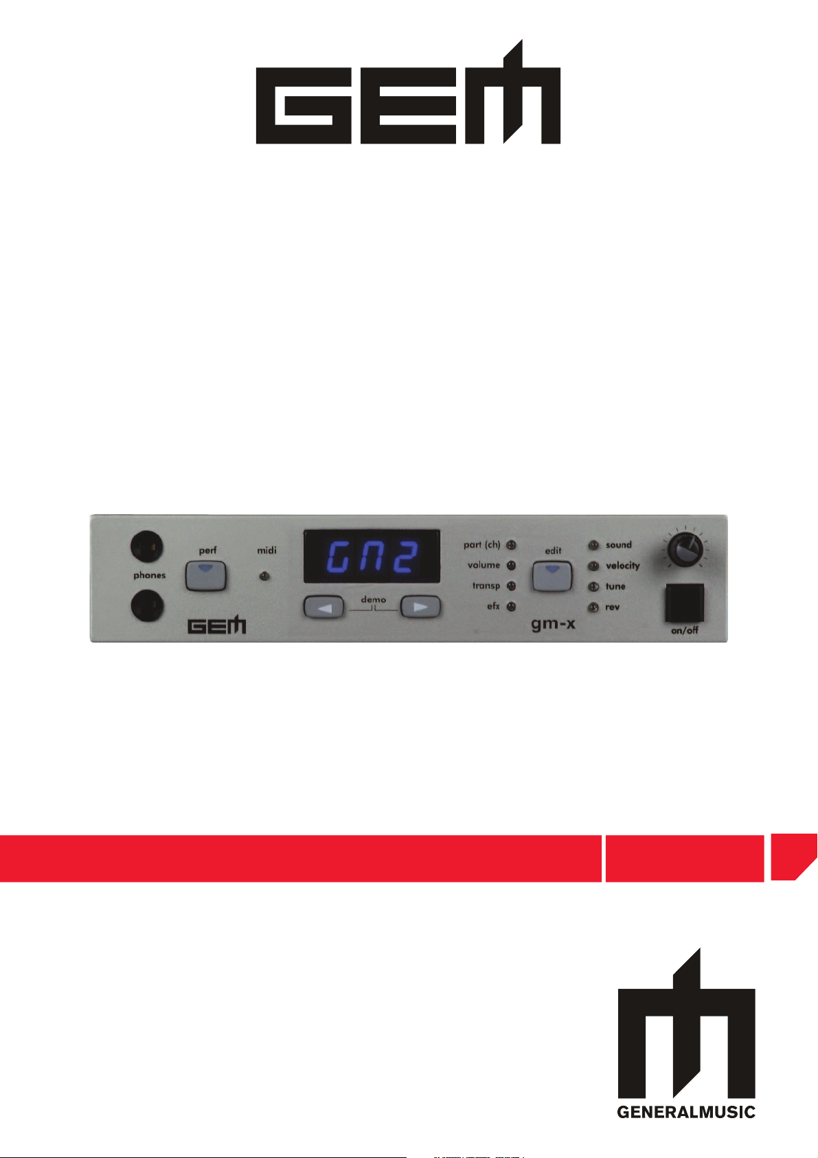
DIGITAL KEY BOARDS
owners manual
•English
gm-x
Page 2
SPECIAL MESSAGES
ALARM SYMBOLS:
Generalmusic electronics prod ucts
could present la bels sim i lar to that
dis played in this section. Please follow
ac cu rate ly the pre cau tions descripted
in the safety instructions.
The exclamation mark within an equi lat er al triangle is
intended to alert.
The lightning fl ash with arrowhead symbol, within an equilateral triangle, is intended to alert the user to the presence of
uninsulated “dangerous voltage” within the product’s enclosure that may be of suffi cient magnitude to constitute a risk of
electric shock to persons.
IMPORTANT NOTE: To reduce the risk related to the correct and normal use of the instrument, all Generalmusic products are accuralety tested
in a safety laboratory. DO NOT modify the present unit, the safety standard and the correct instrument operativity could be com pro mised, and as
a further con se quence the warranty will be invalidated.
This marking shown on the product or its literature, indicates that it should
not be disposed with other household wastes at the end of its working life. To
prevent possible harm to the enviroment or human health from uncontrolled
waste disposal, please separate this from other types of wastes and recycle it
responsibly to promote the sustainable reuse of material resources. Household
users should contact either the retailer where they purchased this product, or
their local government offi ce, for details of where and how they can take this
item for environmentally safe recycling. Business users should contact their
supplier and check the terms and conditions of the purchase contract. This
product should not be mixed with other commercial wastes for disposal.
The declaration of conformity can be downloaded from the
Generalmusic website:www.generalmusic.com
IMPORTANT SAFETY AND INSTALLATION INSTRUCTIONS
INSTRUCTION PERTAINING TO A RISK OF FIRE, ELECTRIC SHOCK, OR INJURY TO PERSONS.
WARNING!
When using electric products, basic precautions should always be followed, including the following:
1. Read all the Safety and Installation instructions and explanations of Graphic Symbols before using the product.
2. This product must be earthed. If it should malfunction or breakdown, grounding provides a path of least resistance for electric
current to reduce the risk of electric shock. This product is equipped with a cord having an equipment-grounding conductor and a
grounding plug. The plug must be plugged into an appropriate outlet that is properly installed and earthed in accordance with all
local codes and ordinances.
DANGER:Improper connection of the equipment grounding conductor can result in a risk of electric shock. Check with a qualifi ed electrician or serviceman if you are
in doubt as to whether the product is properly grounded. Do not modify the plug provided with the product, if it will not fi t the outlet, have a proper outlet installed by a
qualifi ed electrician.
3. To reduce the risk of injury, close supervision is necessary when this product is used near children.
4. Do not use this product near water for example, near a bathtub, washbowl, kitchen sink, in a wet basement, or near a swimming
pool or the like.
5. This product should only be used by a stand or cart that is recommended by the manufacturer.
6. This product, either alone or in combination with an amplifi er and headphones or speakers, may be capable of producing sound levels that could
cause permanent hearing loss. Do not operate for a long period of time at a high volume level or at a level that is uncomfortable. If you experience
any hearing loss or ringing in the ears, you should consult an audiologist.
7. This product should be located so that its location or position does not interfere with its proper ventilation.
8. This product should be located away from heat sources such as radiators, heat registers, or other products that produce heat.
9. The product should be connected to a power supply only of the type described in the operating instructions or as marked on the product.
10. This product may be equipped with a polarized line plug (one blade wider than the other). This is a safety feature. If you are unable to insert the plug
into the outlet, contact an electrician to replace your obsolete outlet. Do not defeat the safety purpose of the plug.
11. The power-supply cord of the product should be unplugged from the outlet when left unused for a long period of time. When unplugging the power
supply cord, do not pull on the cord but grasp it by the plug.
12. Care should be taken so that objects do not fall and liquids are not spilled into the enclosure through openings.
13. The product should be serviced by qualifi ed service personnel when:
A. The power-supply cord or the plug has been damaged
B. Objects have fallen, or liquid has been spilled into the product;or
C. The products has been exposed to rain or moisture
D. The product does not appear to be operating normally or exhibits a marked change in performance
E. The product has been dropped, or the enclosure damaged.
14. Do not attempt to service the product beyond that described in the user-maintenance instructions. All other servicing should be referred to qualifi ed
service personnel.
15. WARNING - Do not place objects on product power cord or place it in a position where anyone could trip over, walk on or roll anything over it. Do
not allow the product, or its bench, or its pedal board to rest on or to be installed over power cords of any type. Improper installations of this type
create the possibility of fi re hazard and/or personal injury.
16. Electromagnetic interference (RFI). This electronic product utilizes digital sampled wave processing technology (S.W.P.) that may adversely affect
radio/tv reception. Read FCC information inside back cover for additional information.
Generalmusic cannot be held responsible for damage caused by improper use or mod i fi ca tions to the
instrument, or data lost or destroyed
Technical specifi cations are subject to change
The information contained in this manual are considered correct at the moment of printing. Generalmusic reserves the
right to change or modify any technical spec i fi ca tion with out prior notice or obbligation to upgrade existing units.
The illustrations and the screens of this manual are for instructional purposes only and may appear different from
those on your instrument.
SAVE THESE INSTRUCTIONS
Page 3

M A N U A L I N D E X
MANUAL INDEX
Introduction
Rear panel and connections
Getting started
Connect a speaker system
Power the expander
Connect to a PC
Connect to a PC via midi
Connect to a PC via usb
Connect a midi master controller
Connect pedals
Using the input connection
Start the gm-x
The default mode (gm2)
Listen to the demo sequence
Edit the default mode (gm2)
Selecting the parts (ch) in gm2 mode
Selecting the parameters to edit in the selected parts (ch): sound
Selecting the parameters to edit in the selected parts (ch): volume
Selecting the parameters to edit in the selected parts (ch): velocity
Selecting the parameters to edit in the selected parts (ch): transpose
Selecting the parameters to edit in the selected parts (ch): tune
Selecting the parameters to edit in the selected parts (ch): efx
Selecting the parameters to edit in the selected parts (ch): rev
The mode "ALL" in edit menu
The performance mode
Enter the performance mode
Select the performances
Manual recalling
Midi recalling
Edit the performance
Memorize the performance
Store the edit in the same performance location
Store the edit in a different performance location
Exit the performance store
Copy the performance
Memory management system
Common channel setting
Midi identification number
System reset
Midi data bulk dump
Sound list
Performance list
Midi implementation chart
Technical specifications
1
1
2
2
2
3
3
3
4
4
4
5
5
5
5
6
6
6
7
7
7
7
8
8
9
9
9
9
9
10
10
10
10
11
14
12
12
12
13
14
15/16
17/18
19
19
Page 4

GM-X Product Package
• gm-x expander
• Owners manual
• Gem PC - Software Editor
• AC Adapter
• MIDI Cable
Page 5
owners manual
gm-x
INTRODUCTION
Congratulations & thank you for purchasing the GEM gm-x Expander. Utilizing our proprietary DRAKE technology, the gm-x produces a vast variety of sounds with exceptional
quality. The gm-x also incorporates an intuitive, yet easy to use operational interface that
will satisfy even the most demanding live or professional studio applications.
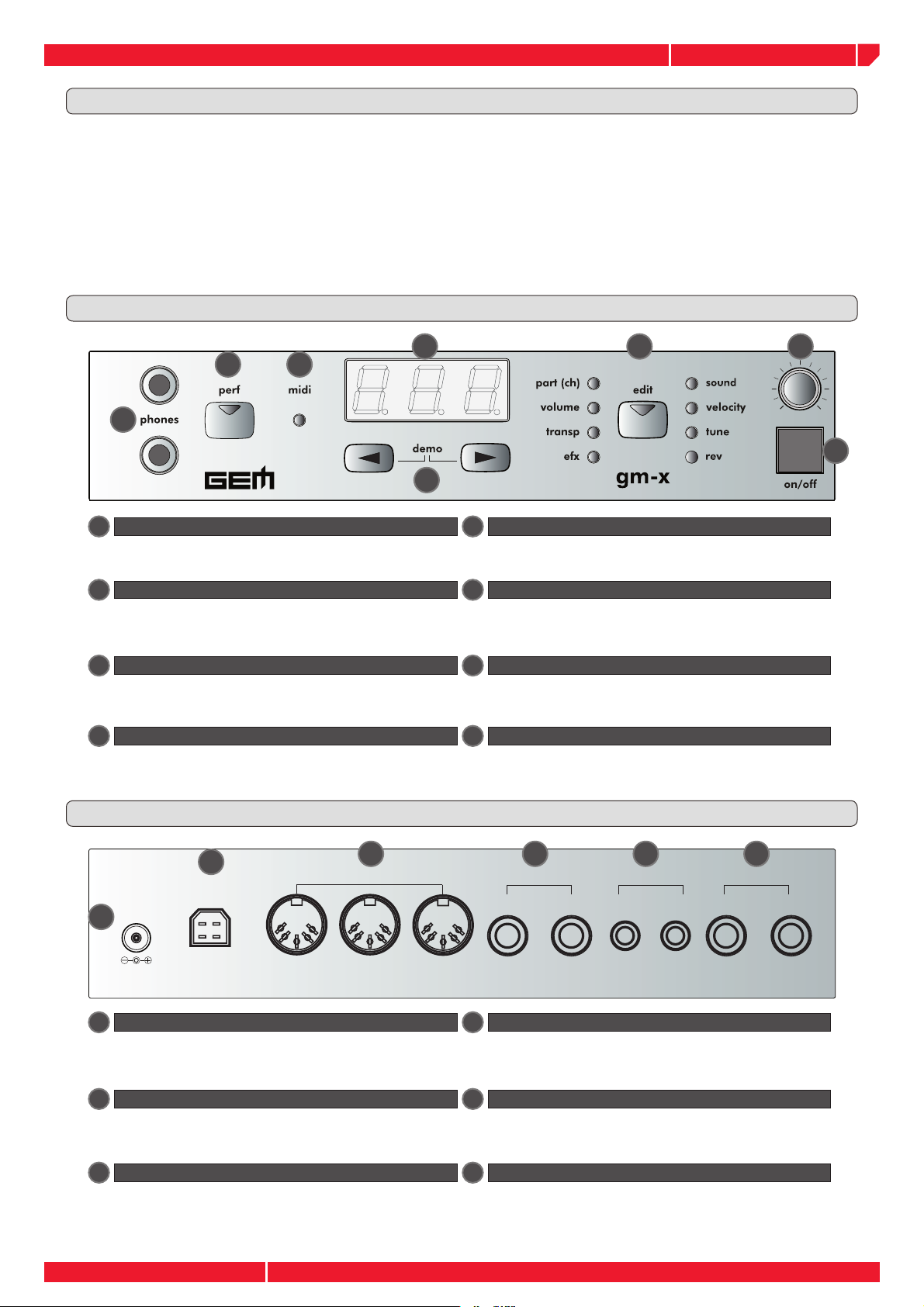
FRONT PANEL
4 5 6
2 3
1
7
8
1
phones edit
Two headphones may be connected to the module.
2
perf
The perf button (PERFORMANCE), select the
performance mode. See the relative chapter, in this
manual.
3
midi
This led monitors the midi data received at the midi
input of the module.
4
display
The 3 digit display visualizes the values and the
parameters of the various editing levels.
REAR PANEL AND CONNECTIONS
3
-)$)
1
$#
2
53"
). /544(25
5
This is used for entering the edit mode and select the
editing parameters.
6
volume
the Volume knob, sets the output level of the
instrument.
7
data entry/demo
These buttons allow you to modify the parameter
values. Both pressed at the same time will start the
demo sequence.
8
on/off
Turns the module on or off.
4
0%$!,3
,2
5
).054
-
2
6
/54054
,
1
12 D.C. in
AC adapter input. In order to avoid possible damage
to the instrument, please only use the adaptor supplied
or specifi ed for this instrument.
2
USB
USB connection to the PC. Use this connection with a
proper USB cable to connect the module to a PC. See
the relative chapter in this manual.
3
MIDI IN-THRU-OUT
The three standard MIDI ports allows the connection of
the instrument to a MIDI controller, such as a Master
keyboard a Midi Accordion or a PC (equipped with
MIDI interface).
4
PEDALS
You may connect two types of pedals to the expander.
An expression pedal to Input #2 and a Gem Multipedal
unit to Input #1.
5
INPUT
The INPUT RCA connectors allows you to plug an
external (Line) source to the instrument. Consult the
relative chapter of this user manual.
6
OUTPUT
Connect the instrument to an external speaker system
or a Mixer.
Page 1
Page 6

owners manual
1
2
3
MIDI fi les Player
Software
GETTING STARTED
The Gem Gm-x expander is a top quality sound generator, designed to be used in the following ways :
1
Connected to desktop or laptop PC via MIDI to play standard midifi les
Connected to desktop or laptop PC via USB to play standard midifi les
2
Played via MIDI from a MIDI master controller such as a digital piano, a master keyboard,
3
a MIDI guitar, a MIDI Accordion.
In this chapter we will cover all the basic steps necessary to properly connect and use the instrument.
POWER THE EXPANDER
gm-x
Connect the adapter to a proper voltage A.C. wall
1
plug.
$# 53"
CONNECT A SPEAKER SYSTEM
Connect audio output of the expander to your live or
2
studio speaker system.
The gm-x expander is a professional sound generator with a
top quality pcm / physical modelling sound library. Always use
an adequate stereo external speaker system in order to get the
maximum performance from this instrument.
Set the
global
Start the
volume
gm-x
NOTE: always turn on the amplifi er of your system after all the others devices.
$# 53"
-)$)
). /544(25
). /544(25
0%$!,3
-)$)
0%$!,3
).054
,2
).054
,2
/54054
2
-
,
/54054
2
-
,
Page 2
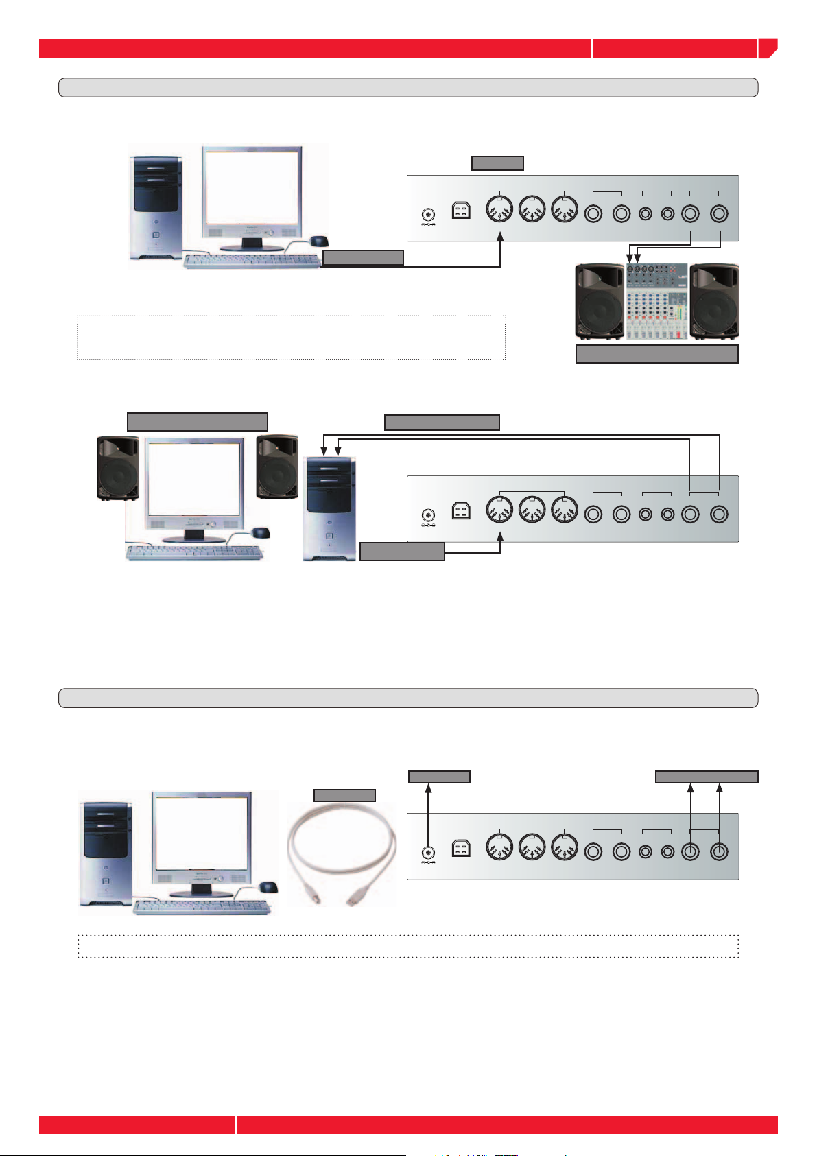
CONNECT TO A PC
The Gm-x expander can be connected to a PC in two different ways: using the MIDI or the USB (Universal Serial
Bus) interface. Using the MIDI the PC has to be equipped with a proper MIDI interface (see the note below), in
case of USB it's possible to use directly the PC USB built-in connection. In both case, MIDI or USB, the transfer
rate and the features of the protocol comply with the standard MIDI specifi cations, the only difference is the
connections type.
After successfully installing suitable player software in your PC, you will be able to play standard MIDI fi les.
MIDI fi les Player
Software
NOTE: Normally a desktop PC offers MIDI connection from an installed audio card. The type of the connection is
dependant from the model of the audio card. In relation to this, please refer to the owners manual of your PC &
or audio card.
Page 7
owners manual
SPEAKER SYSTEM
to the speaker system
D.C. adapter
USB cable
MULTIMEDIA SPEAKER
PC MIDI OUT
AUDIO CARD - LINE IN -
PC MIDI OUT
MIDI IN
gm-x
CONNECT TO A PC VIA MIDI
We will assume that a MIDI interface along with software to play MIDI fi les is correctly installed in your PC. Please refer to the
operating instructions of these devices to properly confi gure the PC to transmit standard MIDI fi les via the MIDI OUT socket.
MIDI IN
0%$!,3
PC MIDI OUT
$# 53"
-)$)
). /544(25
With this confi guration, selecting and playing a standard MIDI fi le from the player
software installed in your computer the expander will play the sequence.
REMEMBER! The MIDI interface does not transmit AUDIO signals, just control
data only. You must always connect the audio output of the MIDI instrument
(such as the gm-x) you are controlling, to an external speaker system
SPEAKER SYSTEM
If your computer is equipped with a multimedia speaker system, it's possible to connect the gm-x to directly the
computer speaker in the following way:
).054
,2
/54054
2
-
,
MULTIMEDIA SPEAKER
Using this type of connection it's possible to listen to the gm-x sounds from the computer speakers, meanwhile the
overall instrument level will be set from the Windows
AUDIO CARD - LINE IN -
$# 53"
PC MIDI OUT
®
multimedia mixer, or from the control drive of other Operat-
-)$)
). /544(25
0%$!,3
).054
,2
/54054
2
-
,
ing System you might have installed in your PC.
CONNECT TO A PC VIA USB
As previously noted, the only difference in MIDI or USB is only the type of connections, the data transfer rate and the
features are the same in both cases.
to the speaker system
USB cable
D.C. adapter
$#
53"
-)$)
). /544(25
0%$!,3
).054
,2
Not included
For instruction on this feature, please refer to the CD ROM included with the expander.
/54054
2
-
,
Page 3
Page 8
owners manual
SPEAKER SYSTEM
MIDI IN
MIDI OUT
AUDIO OUT
EXPRESSION pedal
Perfor-
mance
UP
Perfor-
mance
DOWN
Sound
LONG/
SHORT
Track
MUTE
FX
Bypass
Note
Trigger
MULTIPEDAL
SUSTAIN pedal
SUSTAIN pedal
PIANO TYPE
MIDI IN
MIDI OUT
MIDI MASTER KEYBOARD
MIDI OUT
MIDI ACCORDION
MIDI IN
MIDI IN
MIDI OUT
MIDI THRU
AUDIO
OUTPUT TO
SPEAKER
MIDI IN
INPUT
OUTPUT
Rear Panel
gm-x
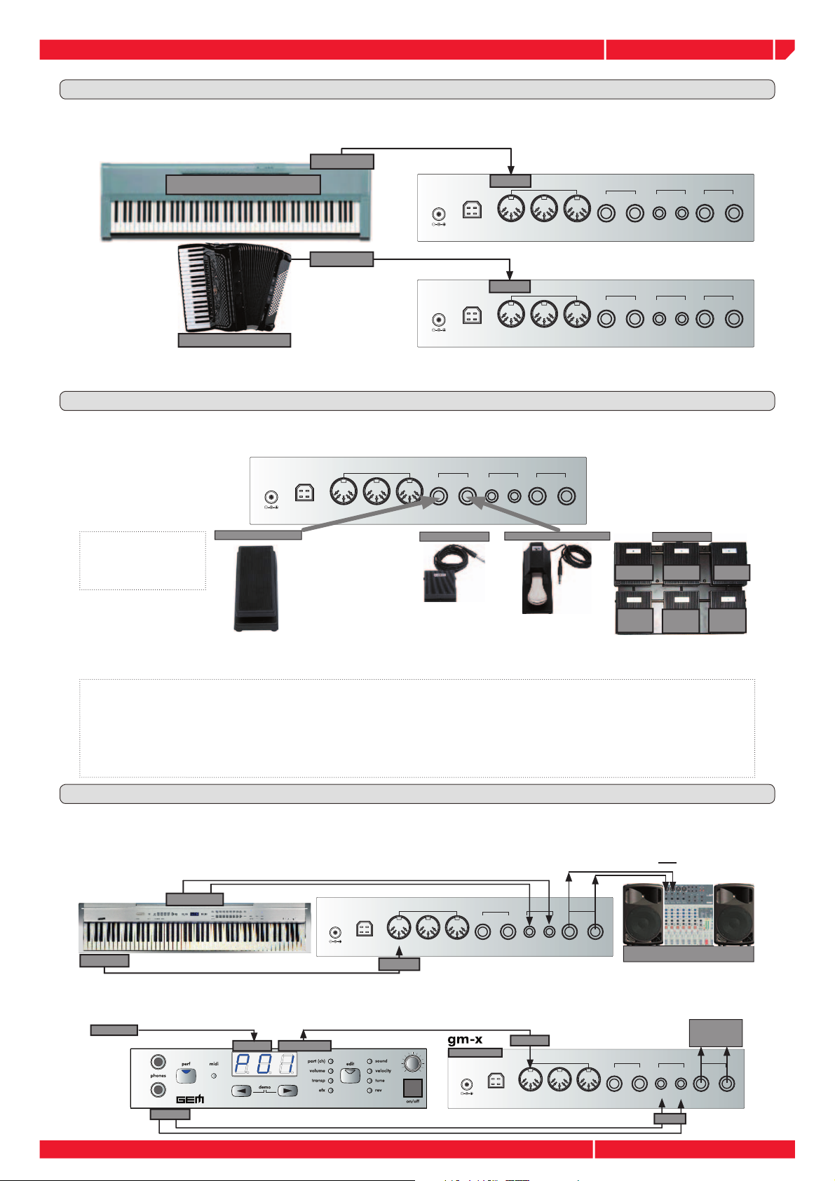
CONNECT A MIDI MASTER CONTROLLER
The gm-x module can be used as a powerful sound expansion for any type of MIDI controller, digital piano,
master keyboard, MIDI guitar and accordion.
MIDI OUT
MIDI IN
MIDI MASTER KEYBOARD
MIDI ACCORDION
MIDI OUT
$# 53"
$#
MIDI IN
53"
-)$)
). /544(25
-)$)
). /544(25
0%$!,3
0%$!,3
).054
,2
).054
,2
In order to achieve the maximum control of the gm-x, please refer to this next chapter where the different parts of the
instrument will be fully explained.
CONNECT PEDALS
Independently of the MIDI or USB controller you're using with the gm-x, it's possible to connect directly to
the module various type of pedals: single switch, multi switch, continuos control.
/54054
2
-
,
/54054
2
-
,
The EXPRESSION
$# 53"
EXPRESSION pedal
-)$)
). /544(25
0%$!,3
,2
SUSTAIN pedal
).054
/54054
2
-
SUSTAIN pedal
,
PIANO TYPE
MULTIPEDAL
pedal can be connected to the Pedal
Input #2 only
code #970013
prod. code
#970116
prod. code
#970134
Track
MUTE
Perfor-
mance
UP
prod. code #970464
FX
Bypass
Perfor-
mance
DOWN
Note
Trigger
Sound
LONG/
SHORT
It is not possible to change these parameters set from the gm-x internal edit menu. However using the advanced PC editor
supplied with the module, it’s possible to edit some of these parameters in a very detailed way.
Note: In the Sound list (page 15/16) you will fi nd Sounds with the (PED) Sign. These are “Special Sound” properly designed to be realtime
switched for example, from a Soft Sax to a Growl Sax, from slow rotary Organ to fast and so on, only by pressing a pedal, with a very
impressive results. For this purpose you can use:
•The GM-X PEDAL input (1 or 2), using a Multipedal unit with the default GM-X confi guration and pressing the PED #3 LONG/SHORT
corresponding to the standard MIDI CC # 67 (SOFT).
•The GM-X PEDAL Input 2 using a single switch pedal. This Pedal input it’s already set on the MIDI CC# 67 (SOFT)
•An external MIDI controller using a pedal properly connected and programmed to transmit the CC# 67 (SOFT).”
USING THE INPUT CONNECTION
The gm-x is equipped with RCA stereo input connections. These jacks allow you to connect another instrument (or external LINE audio source) and mix the signal into the audio OUTPUT of the module.
Please note that the external mixed signal will be not processed in any way from the gm-x, this is a dry input only.
AUDIO OUT
MIDI OUT
$# 53"
). /544(25
MIDI IN
-)$)
0%$!,3
,2
).054
/54054
-
2
,
SPEAKER SYSTEM
This connection allows you to use two mixer inputs to connect a digital piano and the gm-x at the same time.
In the same way, using the input connection it's possible to connect a rp-x (piano sound module), to a gm-x.
MIDI OUT
Page 4
OUTPUT
MIDI IN
MIDI THRU
rp-x
Rear Panel
$# 53"
MIDI IN
). /544(25
-)$)
0%$!,3
,2
).054
INPUT
AUDIO
OUTPUT TO
SPEAKER
/54054
2
-
,
Page 9

owners manual
1
2
START THE gm-x
Once the gm-x module is connected to your controller (via MIDI or USB), it's possible to use it, in the way you prefer.
Use the ON/OFF button on the front panel to switch on the module.
THE DEFAULT MODE (GM2)
After a small period of loading & checking, the display will show the message
“GM2”. The module is ready to perform. .
This is the main status of the instrument, in this default GM2 mode, the gm-x is ready to
respond to any MIDI message over 16 MIDI channels adhering to the features and specifi cation of the General MIDI 2 standard. This is the instrument mode normally used to play
standard MIDI fi les.
LISTEN TO THE DEMO SEQUENCE
The gm-x has an internal DEMO sequence demonstrating the musical quality
& power of the instrument. Press the two DATA ENTRY buttons on the panel at
the same time in order to start the DEMO. The display show the message “DE1”
(Demo 1).
Playing the DEMO. Adjust the instrument output VOLUME, by rotating the VOLUME
knob on the panel.
gm-x
The DEMO sequence contains various MIDI fi les from different musical styles. During playback it’s possible to select each MIDI fi les
or demo song, by simply pressing the DATA button. The display
will indicate the number of the selected MIDI fi le. In the normal
DEMO mode, all the MIDI fi les will be played in chain.
You can exit The DEMO mode by pressing the PERF button on the panel. The
module will return the default mode (GM2).
EDIT THE DEFAULT MODE (GM2)
The default GM2 mode is designed to be connected to a PC playing standard MIDI fi les. In this way, all the
data contained in the MIDI fi les will properly control all of the gm-x track parameters. Should you wish, it’s
temporarily possible to edit the parameters contained in the EDIT menu.
Please note that incoming MIDI messages, such as Program Change or control change will change the modifi ed parameters according to the data contained in the MIDI fi le.
It is not possible to store the edited data in the GM2 mode. These have to be properly changed in your MIDI fi le.
Press the EDIT button to enter the edit
1
menu.
Once the EDIT button is pressed you enter the edit menu starting with the PART (CH). The PART (CH)
parameter allows you to select any of the 16 available multi-timbral parts and their relative MIDI channel. The PART (CH) led, light up in the panel, the currently selected part is showed in the display.
Number of the selected part
Press the DATA button to select the PART
2
(CH) you want to edit
Page 5
Page 10

owners manual
SELECTING THE PARTS (CH) IN GM2 MODE
SELECTING THE PARAMETERS TO EDIT IN THE SELECTED PARTS (CH): SOUND
SELECTING THE PARAMETERS TO EDIT IN THE SELECTED PARTS (CH): VOLUME
SELECTING THE PARTS (CH) IN GM2 MODE
It is possible to select 16 different parts, corresponding
to the 16 standard MIDI channel.
Press repeatedly the DATA button, the display will
show the PART (CH) number you wish to edit
Once all the 16 MIDI channel have been selected, the
display will show the message "ALL". This condition allows
you to modify some parameters values at the same time,
speeding up the editing operation. See on Page N.8, for
further details.
SELECTING THE PARAMETERS TO EDIT IN THE SELECTED PARTS (CH): SOUND
Once you have selected the PART you wish to modify
(#01 in this example), the EDIT menu parameter are
selected by pressing the EDIT button. Each time you
press the button a different parameter is selected.
The current default value of the selected parameter, is shown in the
display. In the part # the sound is: GRAND PIANO, the DOT closest
to the fi rst digit indicates the sound BANK (#01). Please refer to the
included sound list at the end of the manual.
Pressing the DATA button you select the next sound
in the sound database.
In order to ease and speed up the sound selection, the sounds
are mapped according to GM mapping. For each sound it’s
possible immediately to select its VARIATION, (an alternative sound belonging to the same timbrel family, located in
a subsequent bank.)
Each time you press the DATA button a next sound
is selected.
gm-x
The second or third dot lighting on in the display,
indicates the selection of a sound variation located
in a subsequent sound bank.
The GM-X has 4 sound banks in total. From bank 0 (no dot light up
in the display), to bank 3 (three dot ligh up in the display).
SELECTING THE PARAMETERS TO EDIT IN THE SELECTED PARTS (CH): VOLUME
To select the VOLUME parameters of the selected PART
(CH) sound, press the EDIT button once more time. The
current default value of the parameter is indicated in
the display. Volume = 100 in this example.
You can increase or decrease the volume level, by
pressing the DATA buttons. The display show
you in realtime the value changing.
NOTE
Once you have reached the VOLUME = 000, (minimum sound
level), by pressing once more again the DATA button you'll set
the selected part OFF, then the part is disabled.
Page 6
The LED #2 lighting on indicates the selection of the sound bank #2
Volume - Volume +
Part disabled
Page 11

owners manual
SELECTING THE PARAMETERS TO EDIT IN THE SELECTED PARTS (CH): VELOCITY
SELECTING THE PARAMETERS TO EDIT IN THE SELECTED PARTS (CH): TRANSPOSE
SELECTING THE PARAMETERS TO EDIT IN THE SELECTED PARTS (CH): TUNE
SELECTING THE PARAMETERS TO EDIT IN THE SELECTED PARTS (CH): EFX
SELECTING THE PARAMETERS TO EDIT IN THE SELECTED PARTS (CH): VELOCITY
gm-x
It is not possible to access the VELOCITY parameter in GM2 mode. To edit this parameter please consult
the NOTE #2 on next page.
This parameter works in PERF MODE only, after the Mode ALL enabling.
This parameter is GLOBAL, then its setting will affect ALL the 16 parts at the same time.
SELECTING THE PARAMETERS TO EDIT IN THE SELECTED PARTS (CH): TRANSPOSE
TRANSPOSE allows to shift the PART (CH) pitch in a range of +/- 24 semitones.
Press the EDIT button to select TRANSPOSE. The
display indicates the current default value
(TRANSPOSE= 00), in this example.
Pressing the DATA buttons to increase or decrease the PART transpose. The display show you in
realtime the value changing. Each single step (+/- 24)
correspond to a semitone.
Transpose - Transpose +
SELECTING THE PARAMETERS TO EDIT IN THE SELECTED PARTS (CH): TUNE
TUNE allows you to shift the PART (CH) pitch fi ne tuning in a range of : -64/00/+63
Press the EDIT button to select TUNE. The display
indicates the current default value (TUNE= 00), in
this example.
Pressing the DATA buttons to increase or decrease the PART TUNE. The display show you in
realtime the value changing.
Tune -
SELECTING THE PARAMETERS TO EDIT IN THE SELECTED PARTS (CH): EFX
Set the EFX send level (chorus, tremolo, phaser, delay etc.) in the selected PART.
Press the EDIT button to select the EFX. The display
indicates the current default value (EFX=000), in this
example.
Pressing the DATA buttons to increase or decrease the EFX send in the selected part. The display
shows you in realtime the value changing. The parameter range is from 0 to 127.
EFX - EFX +
Tune +
NOTE
It is possible to restore the TRANSPOSE, TUNE and VELOCITY default value , by pressing the two DATA buttons at the same time.
Page 7
Page 12

owners manual
SELECTING THE PARAMETERS TO EDIT IN THE SELECTED PARTS (CH): REV
THE MODE "ALL" IN EDIT MENU
1
2
3
4
SELECTING THE PARAMETERS TO EDIT IN THE SELECTED PARTS (CH): REV
gm-x
Set the REVERB (REV) level in the selected PART.
Press the EDIT button to select the REV. The display
indicates the current default value (REV=080), in this
example.
Pressing the DATA buttons to increase or decrease the REV send in the selected part. The display
shows you in realtime the value changing. The parameter range is from 0 to 127.
REV -
THE MODE "ALL" IN EDIT MENU
REV +
As already described in the previous page, the ALL
mode is a way offer by the gm-x system to speed up
the editing operation for some parameters.
In fact setting the ALL mode in PART (CH) edit and selecting one of the edit parameters (*), the value you
insert affects all the parts at the same time.
VOLUME
VELOCITY
(PERF mode)
TRANSPOSE
TUNE
EFX
REV
(*) The SOUND selection is excluded from the ALL mode.
In ALL MODE sets the GENERAL volume of the instrument.
Set a programmable VELOCITY offset, in order to increase (or decrease) the velocity of incoming MIDI notes transmitted by a MIDI controller. Value range: -64/00/+63. Value= 00 does not affects the original velocity values.
Sets the GLOBAL transpose of the module +/- 12 semitones. This value is added to the PART value. The total
transpose value is: +/- 36 semitones (+/- 24 semitones in PART, plus +/- 12 semitone in ALL mode).
Control the GLOBAL tune of the module, from A = 427 to A= 452 Hz.
Control the effect (EFX) general level.
Control the reverb (REV) general level.
NOTE #1
Selecting the ALL mode the TUNE becomes a GLOBAL parameter.
Editing this parameter the display indicates the detune values in steps
of HERTZ. Range: from A = 427 to A= 452 Hz., A=440 standard
default value.
Tune - Tune +
NOTE #2
The VELOCITY parameter allows you to set a programmable VELOCITY offset, in order to increase (or decrease) the
velocity of incoming MIDI notes transmitted by a MIDI controller. Value range: -64/00/+63. Value= 00 does not affects
the original velocity values.
1
Select the "ALL" mode as explained in the above chapter.
2
Press the PERF button on the panel to enter the PERFORMANCE mode. (See the chapter on the next page)
Press repeatedly the EDIT button to select the
3
VELOCITY parameter. The display indicates the
current default value, in this example.
If you need it, You can set the VELOCITY value, by
4
pressing the DATA buttons. The display show
you in realtime the value changing.
Value range: -64/00/+63
This parameter is GLOBAL, then its setting will affect ALL the 16 parts at the same time and its setting is automatically memorized also
turning off the instrument.
Velocity - Velocity +
NOTE #3
REMEMBER in GM2 mode any PARTS (CH) parameter edit is temporary, in fact the Standard MIDI fi les contains the proper set of parameter for
each tracks and they have priority over the edit you have made.
It can happen that some Standard MIDI fi les may not have a complete set of instructions for tracks parameters recalling. In this case the gm-x
will replace these missing data with the Standard instrument and Parameters default (see the Table).
The PARTS and GLOBAL (ALL mode) data editing such as SOUND, TUNE, TRANSPOSE, etc. will be lost switching off the instrument.The Factory
GM2 default will be automatically restored once the module will be started on again.
Page 8
Page 13

owners manual
MIDI MASTER KEYBOARD
MIDI IN
MIDI OUT
MIDI MASTER KEYBOARD
MIDI IN
MIDI OUT
1
4
7
--0
8
5
2
+
9
6
3
MIDI MASTER KEYBOARD
MIDI IN
MIDI OUT
1
4
7
--0
8
5
2
+
9
6
3
ENTER THE PERFORMANCE MODE
SELECT THE PERFORMANCES
MANUAL RECALLING
MIDI RECALLING
gm-x
THE PERFORMANCE MODE
The PERFORMANCE (PERF) mode is a very important gm-x operating level for live performance. This mode
allows you to program and recall up to 99 different set ups of the instrument in real time; a very useful
function controlling the gm-x from a MIDI master control (keyboard, accordion, guitar etc.).
The data set up stored in the PERF mode are memorized after switching off the instrument.
ENTER THE PERFORMANCE MODE
Press the PERF button to enter the PERFORMANCE selection menu.
The gm-x comes with a complete sets of live performances, programmed by the factory. These performances
allows you to feel the real sound power of this impressive instrument.
Some of these performance are programmed with multi split and layer, please set on ch. 01 the transmission
channel of your MIDI master controller in order to control all the PARTS used on the performance using a
unique MIDI transmission channel. See ahead for further details the chapter MIDI COMMON channel.
SELECT THE PERFORMANCES
Once the PERFORMANCE (PERF) mode is selected, it's possible to recall the internal performance in two
different ways.
MANUAL RECALLING
Press the DATA buttons to select the internal
performances
Please consult the PERF list at the end of the manual to see the performance names and structure (single, layer, Split, etc.)
Performance - Performance +
MIDI RECALLING
MIDI IN
MIDI OUT
MIDI MASTER KEYBOARD
From your MIDI controller send the MIDI Program Change corresponding to the PERFOMANCE you wish to
recall. (Program. Change from 01 to 99).
The way to transmit the MIDI Program Change can differ from one MIDI controller to another, please refer
to the owners manual of your MIDI controller in regards to this purpose.
Please note the MIDI transmission channel of the MIDI controller has to be set to the MIDI ch. # 01
MIDI OUT
MIDI IN
MIDI MASTER KEYBOARD
MIDI OUT
MIDI MASTER KEYBOARD
1
4
7
1
4
7
2
3
5
6
8
9
0
+
MIDI IN
2
3
5
6
8
9
0
+
Page 9
Page 14

owners manual
STORE THE EDIT IN THE SAME PERFORMANCE LOCATION
STORE THE EDIT IN A DIFFERENT PERFORMANCE LOCATION
gm-x
EDIT THE PERFORMANCE
The method to edit the PERFORMANCE is the same process already explained for the GM2 default mode. The
PERFORMANCE mode possesses a very important feature, it’s possible to store (and recall), in the instrument
memory 99 different settings, which are retained in the modules memory after turning off the instrument.
To enter the PERF edit mode press the EDIT button
on the panel
The PART (CH) parameter is automatically selected, meanwhile its current value it's visualized in the display
Modifying any parameters value, the PERF LED on
the panel will start blinking, visualizing the edit
status.
NOTES
The available parameters in PERFORMANCE mode are the same already explained in the GM2 mode. Please refer to the pages 6-8 of this
manual, for the complete editing procedure.
The parameter set directly available from the panel of the gm-x module, both in GM2 or PERF mode is a reduced set than available in the
instrument, (this is due to the simplifi ed navigation system used in the module). The best way to fully edit the gm-x performance is to use the
PC EDITOR software included in the package. This software allows you to easily create or edit all kinds of performances!
MEMORIZE THE PERFORMANCE
STORE THE EDIT IN THE SAME PERFORMANCE LOCATION
Once your PERFORMANCE edit it's complete, press
1
the blinking PERF button on the display.
At this point both the PERF button and the digit
2
"P01" in the display (indicating the number of the
edited performance in this example), blink at the
same time.
Keep the PERF button pressed for at least for 2 sec-
3
onds to store in the current location. The display show
the blinking message "STR" (STORE).
Once the procedure is complete the "STR" display mes-
4
sage will stop blinking. Releasing the PERF button the
number of the current PERFORMANCE is showed again
in the display, to confi rm the STORE operation.
STORE THE EDIT IN A DIFFERENT PERFORMANCE LOCATION
Once your PERFORMANCE edit it's complete, press
1
the blinking PERF button on the display.
At this point both the PERF button and the digit
2
"P01" in the display (indicating the number of the
edited performance in this example), blink at the
same time.
Page 10
It's now possible to select another PERF location using
3
the DATA buttons. It's possible to select any of
the 99 available memory locations.
Once the desired memory location is reached, keep
4
pressed the PERF button at least for 2 seconds to store
data. The display show the message "STR" (STORE).
Once the procedure is complete the "STR" display message
will stop blinking. Releasing the PERF button the number of
the current PERFORMANCE is showed again in the display,
to confi rm the STORE operation.
Page 15

owners manual
gm-x
EXIT THE PERFORMANCE STORE
Once your PERFORMANCE edit is complete, press the
1
blinking PERF button on the display.
At this point both the PERF button and the digit
2
"P01" in the display (indicating the number of the
edited performance in this example), blink at the
same time.
At this stage it's possible to exit the STORE procedure
3
by simply pressing the EDIT button. The LED will stop
blinking and the edited data will be deleted. The
display show again the PERF number you start to
edit, while the EDIT button LED goes OFF.
COPY THE PERFORMANCE
To help the edit operation the module allows you to copy the PERFORMANCE data to any other available location. In
this way it's easier to create, for example, different versions of the same split or layer PERFORMANCE.
Select a performance to be copied.
1
Use the DATA buttons to select a PERFORMANCE
location. It's possible to select any of the 99 available
memory locations.
The selected PERFORMANCE is the SOURCE performance,
the data contained in this location will be copied in a destination memory location you'll select in the next stage #4
Press the EDIT button
2
Press the PERF button in the display, the selected
3
performance number start blinking on the display.
Select a destination memory PERFORMANCE location
4
using the DATA buttons.
Keep the PERF button pressed at least 2 sec. to STORE
5
the PERFORMANCE in the new location
Once the "STR" message stop blinking in the display the
data are now memorized.
Once the procedure is complete the "STR" display mes-
6
sage will stop blinking. Releasing the PERF button the
number of the current PERFORMANCE is showed again
in the display, to confi rm the STORE operation.
The EDIT button LED goes OFF.
Page 11
Page 16

owners manual
MEMORY MANAGEMENT SYSTEM
This menu contains some important function for the global instrument setting:
•COMMON CHANNEL SETTING
•MIDI IDENTIFICATION NUMBER
•SYSTEM RESET
•MIDI DATA BULK
These setting are automatically stored in the expander memory and also saved switching ON/OFF the instrument.
COMMON CHANNEL SETTING
The MIDI COMMON channel is a very useful function allowing a high grade of versatility in MIDI programming.
In the default assign the COMMON channel allows you to control the performances playing and selection using
the MIDI ch.#01 only. Many of the internal gm-x performance are programmed using different parts (and different MIDI channel) in layer or split mode. The MIDI COMMON allows to fully play and select these performances
using a master MIDI controller transmitting in a single MIDI channel.
To enter the MIDI COMMON channel setting mode keep
pressed al least for 2 seconds the PERF and the EDIT buttons at the same time.
Both the pressed button and the PART (CH) LED will blink
in the instrument.
Set the new COMMON using the DATA buttons
gm-x
It is possible to select as COMMON channel any of the 16 available
MIDI channel. As you can see the default of the MIDI COMMON
is set on ch. #01 (see the note below about the MIDI channel).
Press the PERF button to exit the COMMON CHANNEL
setting mode. The LED on the display stop blinking and
the instrument select the default GM2 mode.
-
+
MIDI IDENTIFICATION NUMBER
This function allows to use more than one expander in a MIDI network, assigning an identifi cation number of the
expander. This function is really useful using the gm-x PC editor, where even the software allows to fi x an identifi cation number, in this case it's possible to work with a MIDI sistem composed from two or more module and the relative
editors without confl ict.
Enter the MEMORY MANAGEMENT SYSTEM mode keeping pressed al least for 2 seconds the PERF and the EDIT
buttons at the same time. As already seen, the fi rst menu
is the MIDI COMMON channel setting.
Page 12
Press the EDIT buttons to select the MIDI ID menu, the
display show the default ID set on #01 (ALL MODE).
Select a different MIDI ID according with your needs using the DATA
Press the PERF button to exit the COMMON CHANNEL
setting mode. The LED on the display stop blinking and
the instrument select the default mode.
buttons. Value Range 0-15.
Page 17

owners manual
This function restores the original programmed factory set up of the entire instrument.
Enter the MEMORY MANAGEMENT SYSTEM mode keeping pressed al least for 2 seconds the PERF and the EDIT
buttons at the same time. As already seen the fi rst menu
is the MIDI COMMON channel setting.
Both the pressed button and the PART (CH) LED will blink in
the instrument.
Press the EDIT buttons again and the MIDI ID menu is
selected.
Press the EDIT button again, the display show the fl ashing message "RST", RESET. The RESET menu it's now
selected.
gm-x
SYSTEM RESET
Keep the DATA
the instrument. In this way the factory data set up is fully
restored.
The LED and the display stop blinking and the instrument
select the default GM2 mode.
button pressed (at least 2 sec.) to reset
Page 13
Page 18

owners manual
gm-x
MIDI DATA BULK DUMP
This function transmits the user data contained in the PERFORMANCE to an external MIDI device, such as a PC or a
MIDI recorder to create an archive.
To transmit the data BULK to an external device the gm-x MIDI OUT has to be connected to the MIDI IN of the receiving
data recorder MIDI IN.
Enter the MEMORY MANAGEMENT SYSTEM mode keeping pressed at least for 2 seconds the PERF and the EDIT
buttons at the same time. As already seen the fi rst menu
is the MIDI COMMON channel setting.
Both the pressed button and the PART (CH) LED will blink in
the instrument.
Pressing three time the EDIT button in the panel, in
this way the previous function are selected (MIDI ID,
RESET).
Once the BULK function is reached in the menu, the display show the fl ashing message "BUL", (BULK).
1
2
3
Press the DATA button to start the data transmission.
The data transmission in progress is visualized in the
display with a progressive number, from 0 to 100 (in
percentage).
The data transmission can be interrupted at any time, by pressing
the DATA button. In this case the message “ABT” (aborted)
appears in the display.
Once the data transmission it's completed the message
"EOT" (End of transmission) appears in the display.
At this point it's possible to start a new BULK data transmission (useful in case of error), by simply pressing the
DATA button.
The process starts from the beginning again.
Ecc.
It is possible to exit from the BULK menu by pressing the
EDIT button in the panel.
Or it's also possible to exit the MEMORY MANAGEMENT
SYSTEM mode by pressing the PERF button.
The LED on the display stop blinking and the instrument
return to the default GM2 mode.
Page 14
Page 19

owners manual
A
A
A
Sound Name Bnk MSB Bnk LSB PrgChg Sound Name Bnk MSB Bnk LSB PrgChg
Grand Piano 0 0 0 Sax Soprano 0 0 64
Bright Piano 0 0 1 Sax Alto 0 0 65
CP Grand 0 0 2 Sax Tenor 0 0 66
Honky Tonk 0 0 3 Sax Baritone 0 0 67
Rhodex 0 0 4 Oboe 0 0 68
Dx Piano 0 0 5 Eng Horn 0 0 69
Harpsy 0 0 6 Bassoon 0 0 70
Clavinet 0 0 7 Clarinet 0 0 71
Celesta 0 0 8 Ottavino 0 0 72
Glockenspiel 0 0 9 Flute 0 0 73
Music Box 0 0 10 Recorder 0 0 74
Vibe 0 0 11 Indio Flute 0 0 75
Marimba 0 0 12 Bottle 0 0 76
Xilo 0 0 13 Shakuhachi 0 0 77
TubBel 0 0 14 Whistle 0 0 78
Santur 0 0 15 Ocarina 0 0 79
Drawbar Org 0 0 16 Square 0 0 80
Jazz Perc Org 0 0 17 Saw 0 0 81
B3 Fast Org 0 0 18 Calliope 0 0 82
Church Org 0 0 19 Chiff Lead 0 0 83
Reed Org 0 0 20 Charang 0 0 84
Musette 0 0 21 Solo Vox 0 0 85
Harmonica 0 0 22 Saws 5th 0 0 86
Bandoneon 0 0 23 Bass Lead 0 0 87
Gtr Flamenco 0 0 24 Fantasia 0 0 88
Gtr Steel 0 0 25 Warm Pad 0 0 89
Gtr Jazz Lite 0 0 26 Poly Synth 0 0 90
Gtr Strato 0 0 27 Space Voice 0 0 91
Gtr Mute 0 0 28 Bowed Glass 0 0 92
Gtr Overdrive 0 0 29 Metal Pad 0 0 93
Gtr Distorted 0 0 30 Halo Pad 0 0 94
Gtr Harmonics 0 0 31 Sweep Pad 0 0 95
Bass Acoustic 0 0 32 Ice Rain 0 0 96
Bass Fingered 0 0 33 Sound Track 0 0 97
Bass Picked 0 0 34 Crystal 0 0 98
Bass Fretless 0 0 35
Bass Slap 1 0 0 36 Brightness 0 0 100
Bass Slap 2 0 0 37 Goblin 0 0 101
Bass Synth 1 0 0 38 Echo Drops 0 0 102
Bass Synth 2 0 0 39 Star Theme 0 0 103
Violin 0 0 40 Sitar 0 0 104
Viola 0 0 41 Banjo 0 0 105
Cello 0 0 42 Shamisen 0 0 106
Contrabass 0 0 43 Koto 0 0 107
Tremolo Strings 0 0 44 Kali 0 0 108
Pizzicato 0 0 45 Bag Pipe 0 0 109
Harp 0 0 46 Fiddle 0 0 110
Timpani 0 0 47 Shanai 0 0 111
Strings Ensemble 0 0 48 Tinkle Bell 0 0 112
Strings Ensemble Slow 0 0 49
Syn Strings 1 0 0 50 Steel Drum 0 0 114
Syn Strings 2 0 0 51 WoodBlock 0 0 115
Choir Aahs 0 0 52 Taiko 0 0 116
Vox Ooh 0 0 53 MeloTom 0 0 117
Syn Vox 0 0 54 SynthTom 0 0 118
Orch Hit 0 0 55 Reverse Cymbal 0 0 119
Trumpet Gold (Ped) 0 0 56 Gtr Fret Noise 0 0 120
Trombone 0 0 57 Breath Noise 0 0 121
Bariton 0 0 58 Sea Shore 0 0 122
Trumpet Muted 0 0 59 Bird Tweet 0 0 123
Horns 0 0 60 Telephone 0 0 124
Brass Pop 0 0 61 Helicopter 0 0 125
Syn Brass 1 0 0 62
Syn Brass 2 0 0 63 Gun Shot 0 0 127
gm-x
SOUND LIST
tmosphere 0 0 99
gogo 0 0 113
pplause 0 0 126
Page 15
Page 20

owners manual
Sound Name Bnk MSB Bnk LSB PrgChg Sound Name Bnk MSB Bnk LSB PrgChg
Rhodex Tine 11 0 4 Bass Fing Switch 12 0 33
El Piano 11 0 5 Bass Deep 12 0 38
Coupled Harpsi 11 0 6 Bass Sinus 12 0 39
Bar Chimes 11 0 15 Violin Orch 12 0 40
Theater Organ 11 0 16 Strings Ens Marcato 12 0 48
Rock Organ Slow (Ped) 11 0 18 Flugel Horn 12 0 56
Pipe Church Org 11 0 19 Toto Horns 12 0 60
Accordion Italian 11 0 21 Synt Horn 12 0 62
Bandoneon 2 11 0 23 Sax Alto Vib 12 0 65
Ukulele 11 0 24 Sax Tenor Growl 12 0 66
12 Strings Gtr 11 0 25 Pulse 2 12 0 80
Hawaiian Gtr 11 0 26 Lyle 12 0 81
Clean Gtr 11 0 27 Syn Lead 12 0 82
Gtr Distorted 2 11 0 30 Digital 12 0 83
Bass Fingered Vintage 11 0 33 Sound Track 12 0 84
Strings Chamber 11 0 48 Filt Res 2 12 0 85
Strings Chamber Slow 11 0 49 Decay Lead 2 12 0 86
Choir Aahs 2 11 0 52 Obx 2 12 0 87
Orch Hit Glide 11 0 55 Prophet 2 12 0 92
Trumpet Tjuana 11 0 56 PhatSweep 12 0 95
Horn Solo 11 0 60 Ethnic Gtr 12 0 105
Brass Oct 11 0 61 DrumKit_STD2 12 0 112
Sax Alto 2 11 0 65 DrumKit_ROOM2 12 0 113
Sax Tenor (Ped) 11 0 66 DrumKit_POWER2 12 0 114
Clarinet Liscio 11 0 71 DrumKit_ELECT2 12 0 115
Flute Orchestral 11 0 73 DrumKit_ANALOG2 12 0 116
Pulse 11 0 80 DrumKit_JAZZ2 12 0 117
Phat Synth 11 0 81 DrumKit_BRUSH2 12 0 118
Azimut 11 0 82 DrumKit_SFX 12 0 119
Chopper 11 0 83 String Slap 12 0 120
Jump 11 0 84 Scratch 12 0 121
Filt Res 11 0 85 Thunder 12 0 122
Decay Lead 11 0 86 Horse 12 0 123
Obx 11 0 87 Door Creaking 12 0 124
Prophet 11 0 92 Car Stop 12 0 125
SynBrSweep 11 0 95 Screaming 12 0 126
Wind 11 0 98 Laser Gun 12 0 127
Mandolin 11 0 105 B3 Org Press 13 0 18
DrumKit_STD1 11 0 112 Accordion Italian Touch 13 0 21
DrumKit_ROOM1 11 0 113 Bandoneon Touch 13 0 23
DrumKit_POWER1 11 0 114 Gtr Dist Pwr Soldano 13 0 30
DrumKit_ELECT1 11 0 115 Strings Ens Marcato 13 0 48
DrumKit_ANALOG1 11 0 116 Sax Alto Circus 13 0 65
DrumKit_JAZZ1 11 0 117 Gtr Ovation 13 0 25
DrumKit_BRUSH1 11 0 118 OB8seq 13 0 80
DrumKit_ORCH1 11 0 119 Moog Bass 13 0 81
Gtr Cut Noise 11 0 120 Moog Lead 13 0 82
Flute Key Clk 11 0 121 Analog Synth 13 0 83
Rain 11 0 122 Syn Anlg Brass 13 0 84
Dog 11 0 123 Phat Pad 13 0 85
Telephone 2 11 0 124 Percus Synth 13 0 88
Car Engine 11 0 125 Glass Pad 13 0 89
Laughing 11 0 126 Mondolin Tremolo 13 0 105
Siren 11 0 127 RevrsTexture 13 0 124
Wurlye 12 0 4 TamTam 13 0 125
Fm Piano 12 0 5 TamTam Fx 13 0 126
Musette Touch 12 0 21 Booom 13 0 127
Organ LFO 12 0 23
Nylon Gtr Espana 12 0 24
Gtr Steel 2 12 0 25
Gtr Jazz Standard 12 0 26
Gtr Distorted 3 12 0 30
gm-x
SOUND LIST
Page 16
Page 21

owners manual
gm-x
PERFORMANCE LIST
Prg.Chng #
1 Grand Piano+Strings
2 DX- Piano+Strings
3 Rhodex
4 Thin Rhodex
5 Rhodex Strings
6 Real Wurlixer
7 Wurlyxer Tremolo
8 CP- Grand
9 Clavinet
10 Vibe Split
11 Slow Organ
12 B 3 PRESS
13 Theater Organ
14 Church Organ
15 Musette
16 Harmonica Split
17 Bandoneon
18 Nylon Guit.
19 Steel Guit
20 Steel Guit 2
21 12 String
22 Stratocaster
23 Power Lead Split
24 Real Strings
25 Syn Strings
26 Choir AAH
27 Syn Vox
28 Orchester HIT
29 Trumpet
30 Trombone
31 Mute Trumpet
32 Horns
33 Brass Sect.
34 Syn Brass
35 Syn Horns
36 Alto Sax
37 Tenor Sax
38 Bariton Sax
39 Growl Sax
40 Oboe Strings
41 Clarinet
42 Flute
43 Indio Flute
44 Fantasie
45 Bright Voice
Name
Type Note
Layer
Layer
Single
Single
Layer
Single
Single
Single
Single
Split
Single
Single
Single
Single
Single
Split
Split
Single
Layer
Single
Single
Single
Split
Layer
Single
Layer
Layer
Single
Single
Single
Single
Single
Single
Single
Layer
Single
Single
Single
Single
Split
Split
Split
Split
Layer
Multi
Prg.Chng #
46 Atmosphere
47 Star Theme
48 Sweep Pad
49 Lead solo
50 Saxes
51 Sax+Mute
52 Brass 1
53 Phat Synth
54 Mandoline
55 Mando Tremolo
(PED) 56 Italy Accordeon
57 Recorder/ Split
58 Fantasie
59 Cristal-Strings
60 Barockoco
61 Trumpet Choir
62 Big Choir
63 Orchester Horns
64 Brass Sect 2
65 OB- Brass
66 Syn Lead
67 Syn Lead 2
68 Phat Sweep
69 Lead Split
70 E-Piano Mix
71 Bell Pad
72 Tremolo Strings
73 Pizzicato
(PED) 74 Viola Set
75 Orch Hit Split
76 Nylon Split
77 Jazz Guit. Split
78 Mute delay
79 Stratocaster 2
80 Distortion Split
81 Prophet Vox
82 Phat+Strings
83 Phat Pad delay
(PED) 84 Trumpet+Clarinet
85 Horns+Trumpet
86 Ober Duett
87 Church´n Chor
88 Bright´n Voice
89 Applause
90 Drum SET
Name
Type Note
Multi
Multi
Multi
Single
Multi
Multi
Multi
Single
Split
Multi
Split
Split
Split
Split
Multi
Multi
Multi
Multi
Multi
Layer
Layer
Layer
Layer
Split
Multi
Multi
Single
Single
Layer
Multi
Split
Split
Split
Split
Split
Split
Split
Layer
Layer
Layer
Layer
Layer
Multi
Single
DrumSet
91 Musette Accordeon
92 Oberkrein Duett
93 Accordeon
94 Saxophone
95 Trumpet MIX
96 Accordeon+Trumpet
97 Trumpet + Strings
98 Chor + Sax
99 Mandolin+Strings
Beware!
The Performance #91-99 are programmed to be used with a MIDI accordion. To properly control these performances please
select the Common Channel 15 (or 16).
Page 17
Page 22

owners manual
g
t
g
A
r
y
f
g
,
t
,
y
t
t
A
f
pht
y
,
,
r
t
t
k
A
A
r
A
t
Y
gm-x
MIDI IMPLEMENTATION CHART
Gem
Model GM-X
Function Transmitted Recognized NOTE
Basic Default x 1-16
Channel Changed x 1-16
Mode Messa
Note numbe
Velocit
Channel Aftertouch x o
Pitch Bend x o
Control Chan
Program Change x o
e0
32 x o Bank Selec
1 x o Modulation
5 x o Portamento time
6
38 x o Data Entr
7 x o Volume
10 x o Pan Po
11 x o Expression
64 x o Sustain
65 x o Portamento
66 x o Sostenuto
67 x o Sof
71 x o Filter Resonance
72 x o Release time
73 x o
74 x o Filter Cut Of
75 x o Decay Time
76 x o Vibrato Rate
77 x o Vibrato De
78 x o Vibrato Dela
84 x o Portamento control
91 x o Reverb send level
93 x o Chorus send level
98
99 x o NRPN LSB, MSB
100
101 x o RPN LSB, MSB
MIDI Implementation Chart
Defaul
es x Mode 3, 4
ltered **********
Note On x o
Note Of
True Numbe
x Mode 3
x 0-127
xo
********* 0-127
These data are memorized also
switchin
ttack Time
Date:
ott-06
Version: 1.00
the module OFF
System exclusive o o
System Common Song Position x x
Song Selec
Tune Reques
System Real-Time Cloc
Commands x x
uxiliary Messages
Mode 3: OMNI OFF, POL
Mode 4: OMNI OFF, MONO x: NO
ll sound OFF x o
Resel ALL Controlle
LOCAL ON/OFF x x
ctive Sensing x x
System Rese
xx
xx
xx
xo
xx
o: Yes
Page 18
Page 23

owners manual
gm-x
TECHNICAL SPECIFICATIONS
Type
Polyphony
Sounds
Display
Performance Mode
GM- Mode
Multi Mode
Output
Input
Midi
Pedals
Headphones
Mastervolume
Edit-Mode
Effects
DSP technology
memory size
Extra info
USB
PC- Software
Manuals
Weight
Dimensions
GM- Standard expander + Special Sounds
64- Notes max.
248 pcm/physical modelling sounds (GM Standard compatible)
3 digit LED Display
99 Performances
16 Parts / 16 Channel
16 - Parts
1 x Stereo out (Left + Right Jack)
1 x Stereo in (Left + Right RCA)
In/ Out / Thru
1 x Continuos control (optional Expression)
1 x Single switch or multipedal (optional)
2 x headphones
Master Volume knob
Part (ch), Sound, Volume, Velocity, Transpose, Reverb, EFX, Tune
6 Reverb (Room: small, medium, large; Hall: Large, Medium; Stage)
4 Effects: Chorus, Phaser, Tremolo, Stereo Delay)
D.R.A.K.E. by Generalmusic
Flash Ram 64 MB
Midi Velocity Fix IN / PC editor, "easy to use" interface
USB
Gm-x PC editor
English, Italiano, Deutsch, Français
2,5 Kg./5,5 lbs
218 x 44 x 198 mm/ 8,5 x 1,7 x 7,8 inch
Page 19
Page 24

Generalmusic S.p.A. Via delle Rose, 12
47842 S.Giovanni in Marignano (RN) - Italy
Tel. +39 0541 959511Fax +39 0541 957404 www.generalmusic.com
 Loading...