

Page 1
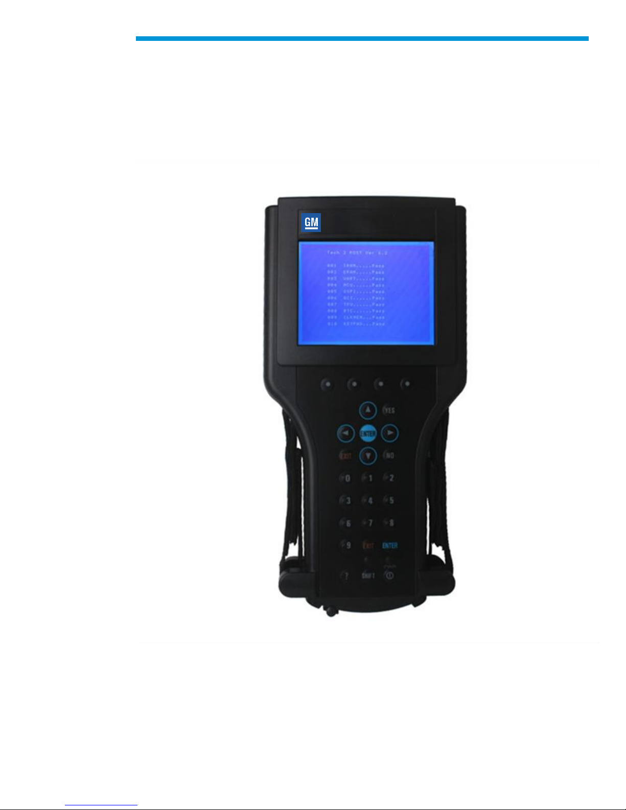
General Motors Tech2 User Guide
GM Tech2 User Guide
1
Page 2

General Motors Tech2 User Guide
GM Tech2 User Guide
The Tech2 User’s Guide provides a comprehensive overview of the Tech2 scan tool.
Everything contained in this manual is based on the latest product information available at
the time of publication. The right is reserved to make changes at any time without notice.
No part of this publication may be reproduced, stored in any retrieval system, or
transmitted in any form by any means, including but not limited to electronic, mechanical,
photocopying, recording, or otherwise, without the prior written permission of GM Service
and Parts Operations. This includes all text, tables, illustrations, and charts.
© 2014 GM Service and Parts Operations. Made in the U.S.A. All rights reserved.
® Tech2 is a registered trademark of General Motors Corporation.
2
Page 3

General Motors Tech2 User Guide
Table of Contents
GM Tech2 User Guide.............................................................................................................2
Table of Contents ....................................................................................................................3
Customer Support Overview ...................................................................................................4
Declaration of Conformity ........................................................................................................5
Important PC Hardware Guidelines ........................................................................................6
Limited Warranty .....................................................................................................................7
Using This Manual ...................................................................................................................8
Tech2 Overview .....................................................................................................................11
Care & Cleaning ....................................................................................................................15
Getting Started.......................................................................................................................16
Initial Hardware Installation ..............................................................................................16
PCMCIA Card Removal ....................................................................................................23
PCMCIA Card Insertion ....................................................................................................23
Vehicle Communications Interface Module Removal ......................................................25
Tech2 Keypad ...................................................................................................................28
Tech2 Connection to Vehicle............................................................................................31
Tech2 Connection to TIS2Web Computer .......................................................................33
Power Supplies ......................................................................................................................35
Adapters.................................................................................................................................38
Software .................................................................................................................................84
Tech2 Main Menu .............................................................................................................84
TIS2Web .........................................................................................................................108
The Service Programming System (SPS) ......................................................................118
CANdi Module .................................................................................................................140
3
Page 4

General Motors Tech2 User Guide
Customer Support Overview
Independent Repair Customers can obtain assistance with a question or problem
concerning the operation of the Tech2 and its attached products, telephone the ACDelco
Aftermarket Support Center.
Before Calling
Before making a call to the ACDelco Aftermarket Support Center, be sure to have the
following information ready:
• Business name, address and ACDelco TIS2Web login
• Telephone number where the technician may be reached
Prepare a brief description of the problem:
• Tell when the problem occurred
• List any error codes displayed
• Tell what accessories were being used when the problem occurred, and vehicle
information
Making the Call
Independent automotive customers with an authorized purchase of TIS2Web may contact
the ACDelco Aftermarket Support Center for assistance with the TIS2Web application.
The ACDelco Aftermarket Support Center telephone lines operate from 8:00 a.m. to 8:00
p.m. (Eastern Standard Time) Monday through Friday. In the United States and Canada to
contact Customer Support, dial:
1.888.212.8959
4
Page 5

General Motors Tech2 User Guide
Declaration of Conformity
Tester: Tech2 Assembly, VTX
Tech2 Tester
F-00K-1040892
Type of product: Automotive Diagnostic Tester
Compliance with the harmonized Norms and Standards listed below proves the conformity
of the Tester: Tech2 Assembly, VTX with the provisions of the EC directives, in particular;
DIN EN 61326:1997, with attachment 1:1998 and attachment 2:2001
The declaration certifies the conformity with the indicated directives and norms, but does
not constitute a representation of properties. The safety hints of the product and product
documentation have to be followed in any case.
Relevant Components:
02003214 Tech2 DLC cable
02002994 _001 Tech2 32 MB PCMCIA card
02002955 Tech2 J1962 16/19 pin adapter
02002953 Tech2 DLC loopback adapter
02002961 Tech2 NAO 12/19/pin adapter
Manufacturer’s Name: Bosch Diagnostics
Manufacturer’s Address: 2030 Alameda Padre Serra
Santa Barbara, CA 93103-1716
805 966.2100
5
Page 6

General Motors Tech2 User Guide
Important PC Hardware Guidelines
ACDelco provides IT guidelines to help users have a seamless experience when using
TIS2Web software applications. To avoid unnecessary compliance issues with TIS2Web,
please review and adhere to the stated infrastructure guidelines at the following link:
http://www.gmdesolutions.com/services/standards.php
These guidelines for GM Dealers also apply to independent users, Professional Service
Centers and Key Fleets using ACDelco Aftermarket subscriptions. For questions on these
guidelines, contact 888-212-8959, prompt #2.
6
Page 7

General Motors Tech2 User Guide
Limited Warranty
SOFTWARE: Bosch Diagnostics/Vetronix warrants for a period of ninety (90) days from
the date of purchase that the Bosch Diagnostics/Vetronix software product will execute its
programming instructions when properly installed. Bosch Diagnostics/Vetronix does not
warrant that the operations of the Bosch Diagnostics/Vetronix software will be
uninterrupted or error free. In the event that this Bosch Diagnostics/Vetronix software
product fails to execute its programming instructions during the warranty period, the
remedy shall be a replacement of such software product.
LIMITATION OF WARRANTY: Bosch Diagnostics/Vetronix makes no other express
warranty, whether written or oral with respect to this product. Any implied warranty of
merchantability or fitness for or a particular purpose is limited to the 90-day duration of this
written warranty. Some states or provinces do not allow limitations on how long an implied
warranty lasts, so the above limitations or exclusion may not apply to you.
EXCLUSIVE REMEDIES: The remedies provided above are Customer’s sole and
exclusive remedies. In no event shall Bosch Diagnostics/Vetronix be liable for any direct,
indirect, special, incidental or consequential damages (including lost profit) whether based
on warranty, contract, tort or any other legal theory.
7
Page 8

General Motors Tech2 User Guide
Using This Manual
To increase their effectiveness with the Tech2, users should familiarize themselves with
the format and information contained in this guide.
Vehicle System Familiarity
While the Tech2 is a powerful tool, it cannot replace knowledge and skill. To obtain
maximum benefit from the Tech2, service technicians must have a complete
understanding of vehicle systems.
When using the Tech2 to diagnose a vehicle, it is recommended that service technicians
also refer to the service manual and the latest service bulletins.
Disclaimer
The Tech2 is designed for use by trained service personnel only. It has been developed for
the sole purpose of diagnosing and repairing automotive systems with electronic controls
and interfaces.
Every attempt has been made to provide complete and accurate technical information
based on factory service information available at the time of publication. However, the right
is reserved to make changes at any time without notice.
8
Page 9

General Motors Tech2 User Guide
Things You Should Know
CAUTION: EXHAUST GAS
When performing any checks with the engine running in an enclosed space such as a
garage, ensure proper ventilation. Never inhale exhaust gases; they contain carbon
monoxide—a colorless, odorless, extremely dangerous gas that can cause
unconsciousness or death.
CAUTION: PARKING BRAKE
To help avoid personal injury, always set the parking brake securely and block the drive
wheels before performing any checks or repairs on the vehicle.
CAUTION: SPARKS
The Tech2 uses parts that can produce arcs or sparks. When used in a garage
environment, the Tech2 must be located not less than 18 inches (460 mm) above the floor.
NOTICE:
• DO NOT clasp battery clamps together when connected simultaneously to the
vehicle’s 12 volt cigarette lighter or power supply. Reverse polarity in the vehicle’s
cigarette lighter may be present. Damage could occur to the Tech2 or to the vehicle.
• If power is applied to the Tech2 and the display remains blank, reverse polarity in the
cigarette lighter may be present. Damage to the Tech2 could occur. DO NOT connect
the DLC cable to the vehicle. Verify that the center contact of the vehicle’s cigarette
lighter has +12 volts and that the outer contact is grounded.
• Turn off the power before inserting or removing the PCMCIA card. Continual removal
and reinsertion of this card is not recommended.
• Align all cards and components carefully before inserting them into the Tech2
• Do not place the Tech2 so that the tilt stand can make contact with the vehicle
battery terminal as this could short out the battery.
9
Page 10

General Motors Tech2 User Guide
Federal Communications Commission (FCC)
Compliance
This equipment has been tested and found to comply with the limits for a Class A digital
device, pursuant to Part 15 of the FCC rules. These limits are designed to provide
reasonable protection against harmful interference when the equipment is operated in a
commercial environment.
This equipment generates, uses, and can radiate radio frequency energy. If not installed
and used in accordance with the instruction manual, it may cause harmful interference to
radio communications. Operation of this equipment in a residential area is likely to cause
harmful interference’s in which case the user will be required to correct the interference at
his or her own expense.
10
Page 11
General Motors Tech2 User Guide
Product
Number
Product Name
3000094
GM Tech2 Unit
Part Number
Base Kit
Tech2 Overview
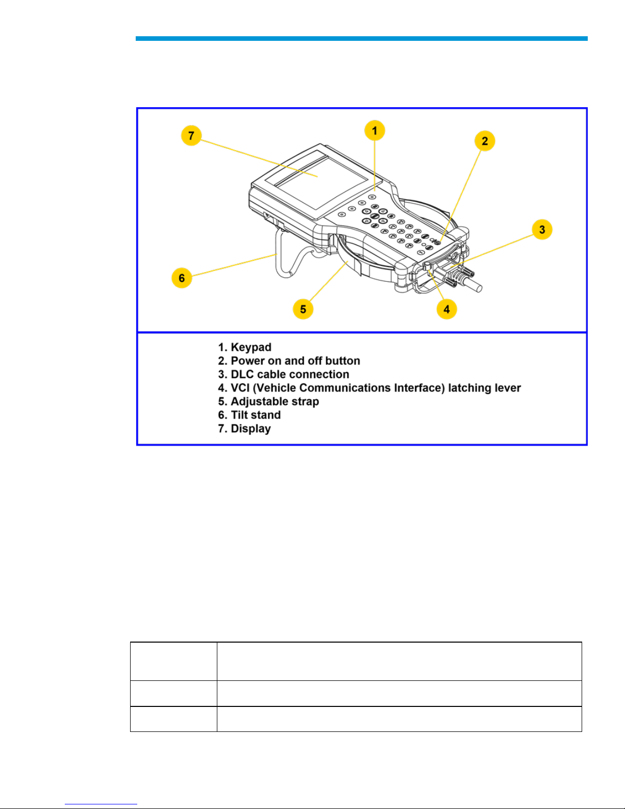
The Tech2 is a hand-held computer designed to aid in diagnosis and repair of automotive
systems with electronic controls and interfaces.
External Features of the Tech2 (front view)
Hardware
The Tech2 has been designed as a rugged, shop-ready tool by having:
• A sturdy case
• A sealed keypad
• Heavy-duty cables and connectors
You can expect years of trouble-free service if you take reasonable care of the Tech2 and
follow the maintenance procedures outlined in Section II.
Your Tech2 will be composed of a base kit and a variety of the following subcomponents:
11
Page 12

General Motors Tech2 User Guide
3000095
3000096
3000097
3000098
3000109
3000110
3000111
3000112
3000116
DLC cable
Cigarette lighter power cable
Battery power cable
SAE 16/19 pin adapter
DLC loopback adapter
RS-232 cable
RS-232 DB9 adapter
RS-232 loopback adapter
Storage case
Part Number
Adapter or Accessory
3000099
3000100
3000101
3000102
3000164
J-45211
J42236-A
J-42598-20
NAO 12/19 adapter
Opel 10/19 adapter
SAAB 10/19
Opel/Isuzu/Geo 3/19 adapter
CANdi* module
Control module stand-alone programming adapter (Cadillac)
Serial data link tester (Corvette Star Tool)
90-degree adapter kit (includes connectors J-42598-21 and J-42598-
22
Table listing Tech2 base kit part numbers and descriptions. See illustrations
Note: Every Tech2 kit does not include every adapter listed.
*Controller Area Network diagnostic interface
Power Supply
The Tech2 can be powered from:
• The automobile battery power cable
• The cigarette lighter power cable
• The Tech2 power supply
• The DLC (Data Link Connector) connection in most vehicles
12
Page 13

Part Number
Power Accessory
3000113
3000115
3000141
3000142
3000143
3000144
3000145
3000146
3000147
3000148
NAO power supply
Universal power supply*
NAO power cable UL 125-127 volts AC/10 amps
Universal power cable IEC 250 volts AC/10 amps*
Universal power cable BS 250 volts AC/5 amps*
Universal power cable AS 250 volts AC/7.5 amps*
Universal power cable SI 250 volts AC/6 amps*
Universal power cable SI 250 volts AC/6 amps*
Universal power cable JIS 125 volts AC/12 amps*
Universal power cable SI 250 volts AC/6 amps*
Part Number
PCMCIA Kit
3000118
32 MB PCMCIA card
User documentation
*European and international use
Table listing part numbers for Tech2 power supplies and cables.
General Motors Tech2 User Guide
Commands
The Tech2 prompts you to enter commands via the membrane keypad for:
• Retrieving and viewing diagnostic information
• Selecting self tests
• Performing vehicle diagnostics
Data Storage
The Tech2 contains electronic components called PCMCIA (Personal Computer Memory
Card Industry Association) cards, which store diagnostic programs. The Tech2 can be
updated as vehicle models change by reprogramming the PCMCIA card via the RS-232
connector.
Table showing the PCMCIA kit part number and description
13
Page 14

CONDITIONS
SPECIFICATIONS
Temperature
Operating: 0 to 40°C (32 to 104°F )
Non-operating: -40 to 70°C (-40 to 158°F )
Relative Humidity
Operating: 15 % to 95% at 40°C (non-condensing )
Non-operating: 90% at 65°C (non-condensing )
Mechanical Dimensions
The dimensions of the Tech2 are as follows:
• Width – 6.1 inches (155 mm)
• Height – 11.8 inches (300 mm)
• Depth – 2.0 inches (55 mm)
• Weight – 2.2 pounds (1.0 kg)
Environmental Specifications
General Motors Tech2 User Guide
Warranty
The Tech2 is warranted against defects in materials and workmanship by the manufacturer
for 24 months beginning five days after the date of shipment to your service center.
If your Tech2 must be sent in for repair, contact Vetronix Corp. 1.800.321.4889, option 7.
Use the package that the replacement arrives in to return the defective unit. You can
contact the ACDelco Aftermarket Support Center at 1.888.212.8959 for the exact
exchange procedure. If notification of defect is received during the warranty period, the
part listed in figures I-2, I-3, I-4, or I-5 that is defective will be replaced. You must return the
defective unit as directed, or you will be charged for the replacement.
Important: This warranty does not cover any part that has been abused, altered, used for
purpose other than which it was intended, or used in a manner inconsistent with
instructions regarding use. This includes, but is not limited to, removal of any Tech2
screws.
14
Page 15

General Motors Tech2 User Guide
Care & Cleaning
After using the Tech2, a few simple steps will insure that you get the most life out of this
diagnostic tool.
NOTICE: Do not spray or pour cleaner anywhere on the Tech2. If the Tech2 should
become dirty, clean it with a mild detergent or hand soap. Avoid using harsh solvents such
as petroleum-based cleaning agents: acetone, benzene, trichlorethylene, etc. Harsh
solvents can etch Tech2 plastic surfaces.
Although the Tech2 is water resistant it is not waterproof, so be sure to thoroughly dry off
the Tech2 prior to usage and/or storage.
Maintenance of the Tech2 requires periodic inspection and cleaning of:
• The display window
• The keypad
• The cable assemblies and connectors
Make sure the Tech2 is not connected to a vehicle or other power source and follow the
cleaning procedures detailed below.
Cleaning the Display
The display collects dust and grime during normal use. Occasionally wipe the screen with
a clean, soft, static-free cloth. Remove stubborn stains by applying a non-abrasive glass
cleaner to a soft cloth and wipe cloth across display area.
Cleaning the Keypad
Clean the keypad with a non-abrasive cleaner. Apply a small amount of cleaner on a soft
cloth and wipe cloth across keypad area.
Maintaining the Cable Assemblies and Connectors
Inspect cable assemblies during connection and disconnection to components. Watch for
any cuts or abrasions along the cables. Check the connectors and connector pins for
grease, dirt and corrosion. If contaminants are present, remove them with a mild soap
solution.
Storing the Tech2
• Store the Tech2 away from solvents and other liquids. It is NOT moisture proof.
• Store the Tech2 away from direct sunlight. Ultraviolet and infrared light will darken
the display.
• Store the Tech2 in its plastic case. Otherwise, the high-impact plastic cover could
become scratched.
15
Page 16
General Motors Tech2 User Guide
Getting Started
This section covers all Tech2 vehicle applications. Therefore, some of the information
provided may not be required for individual applications.
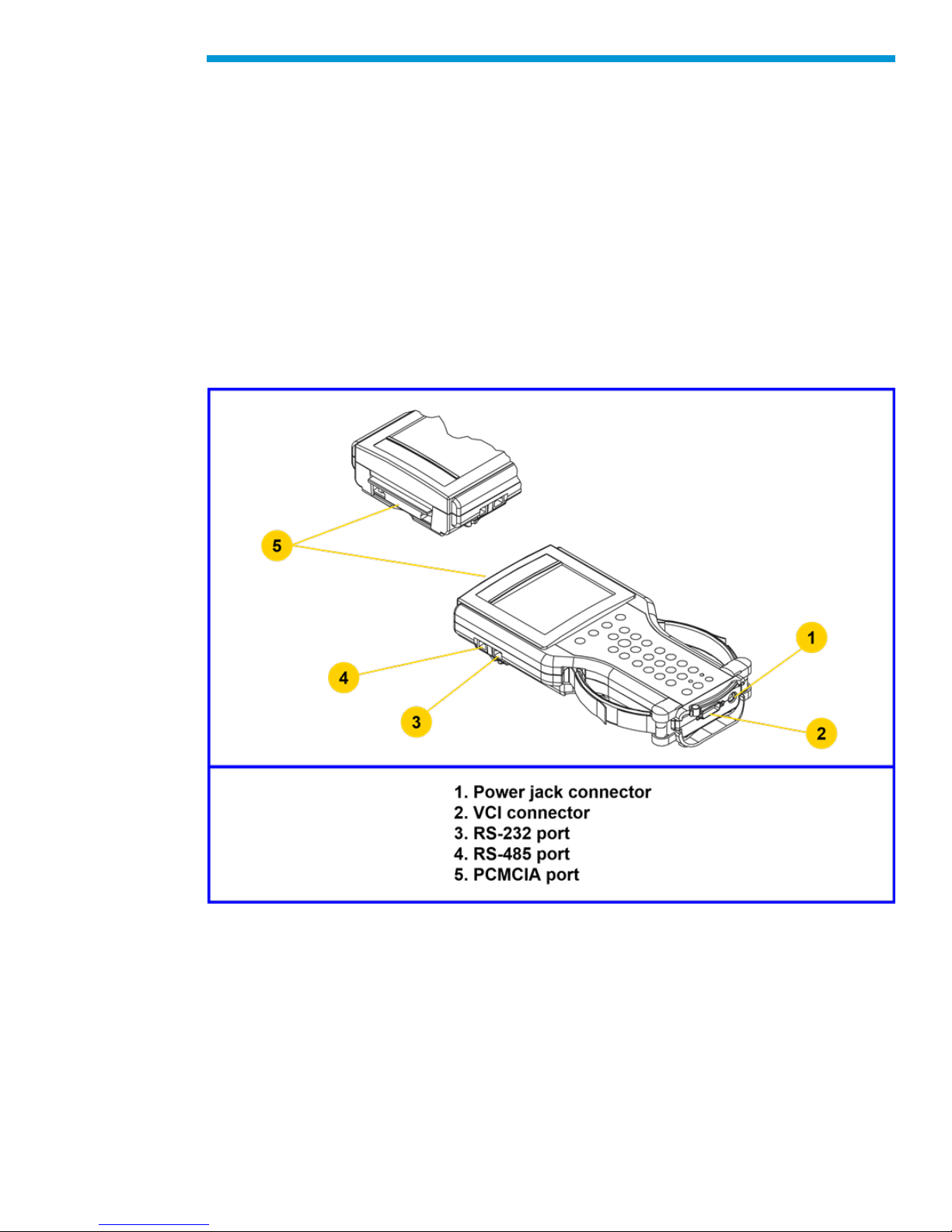
The Tech2 contains two serial communication ports: the RS-232 and the RS-485. Use the
RS-232 port for downloading data from another computer to the Tech2. The RS-485 port is
currently not used.
The Tech2 also contains two PCMCIA ports, a power jack connector, and a Vehicle
Communications Interface (VCI) connector. One of the PCMCIA slots contains a memory
card with diagnostic information. The power jack accepts power from the AC/DC power
supply, battery, or cigarette lighter power cable. The VCI connector accepts the DLC cable
or DLC loopback adapter.
Notice: When using the Tech2 for vehicle communications, the power jack must be
connected to the Tech2 DLC loopback adapter
Identification of the Tech2’s external ports
Initial Hardware Installation
The Tech2 hardware initial installation requires the following seven tasks:
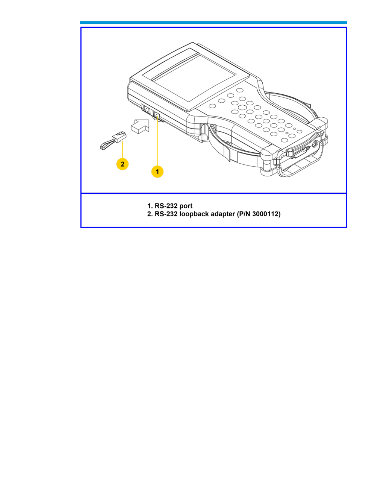
1. Remove the RS-232 loopback adapter (P/N 3000112) from the storage case (P/N
3000116). Plug it into the RS-232 port
16
Page 17
General Motors Tech2 User Guide
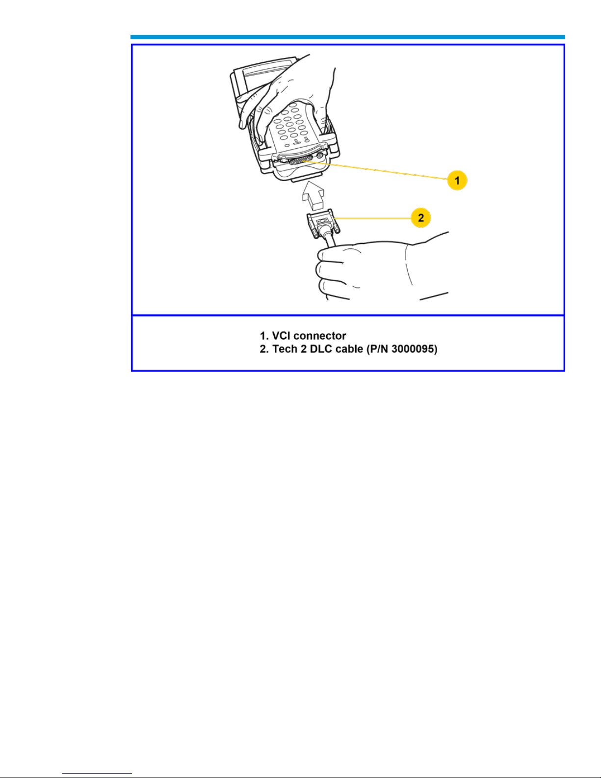
2. Attach the Tech2 DLC cable (P/N 3000095) to the VCI connector
17
Page 18
General Motors Tech2 User Guide
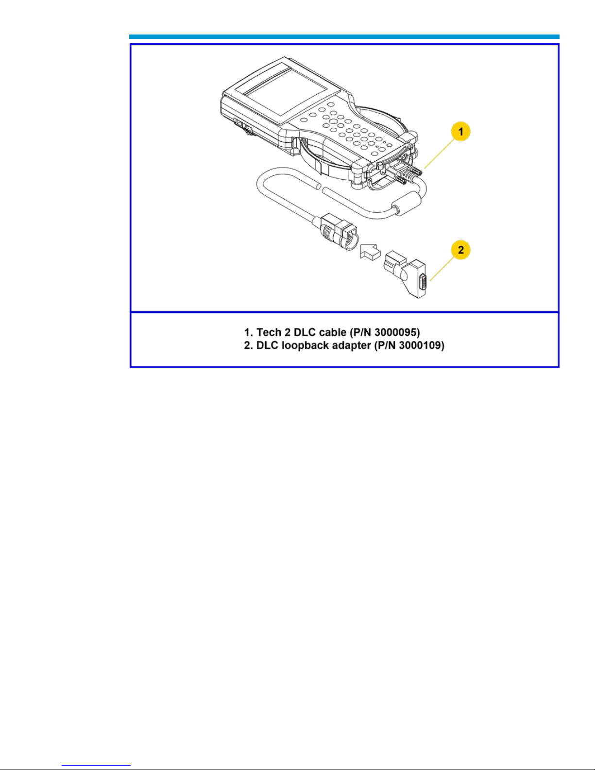
3. Locate the DLC loopback adapter (P/N 3000109) in the storage case. Attach it to the
DLC cable
18
Page 19
General Motors Tech2 User Guide
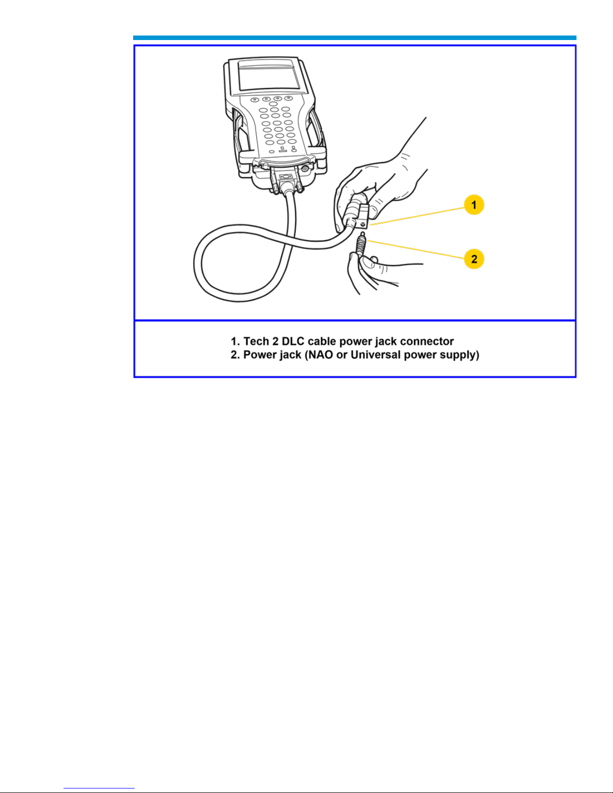
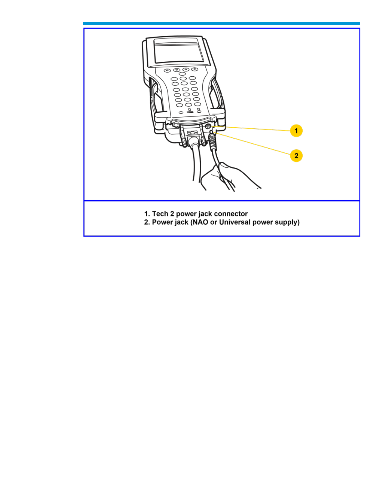
4. Locate the NAO (P/N 3000113) or Universal (P/N 3000115) power supply and
appropriate power cord in the storage case. Insert the power jack into the Tech2 DLC
cable or into the bottom of the Tech2 next to DLC cable connector.
19
Page 20
General Motors Tech2 User Guide
Connection of the power jack to the DLC cable
20
Page 21
General Motors Tech2 User Guide
5. Turn on power by pressing the PWR button located on the Tech2 keypad.
6. Tech2 hardware will be verified automatically by the POST test. (For information on
this program, Troubleshooting.)
7. Disconnect the RS-232 loopback adapter, the power supply, and the DLC loopback
adapter and return to the Tech2 storage case.
21
Page 22

General Motors Tech2 User Guide
22
Page 23
General Motors Tech2 User Guide
PCMCIA Card Removal
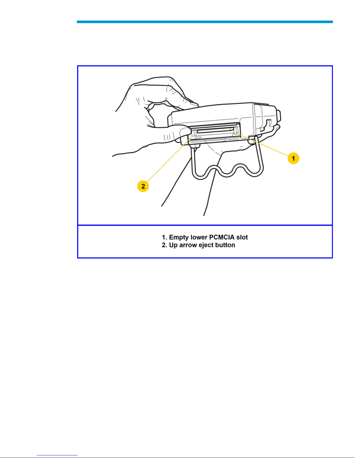
The PCMCIA Card is accessed by opening the hinged door located at the top of the
Tech2. The card is found in the upper slot. The lower slot will be used for future
enhancements. Press the arrow button (located beside the slot) to eject the card.
Ejection of PCMCIA card
PCMCIA Card Insertion
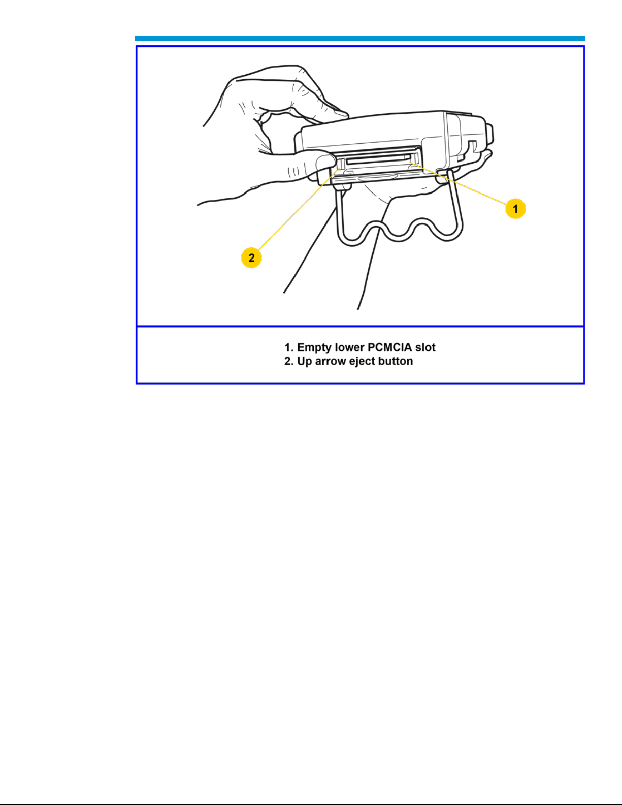
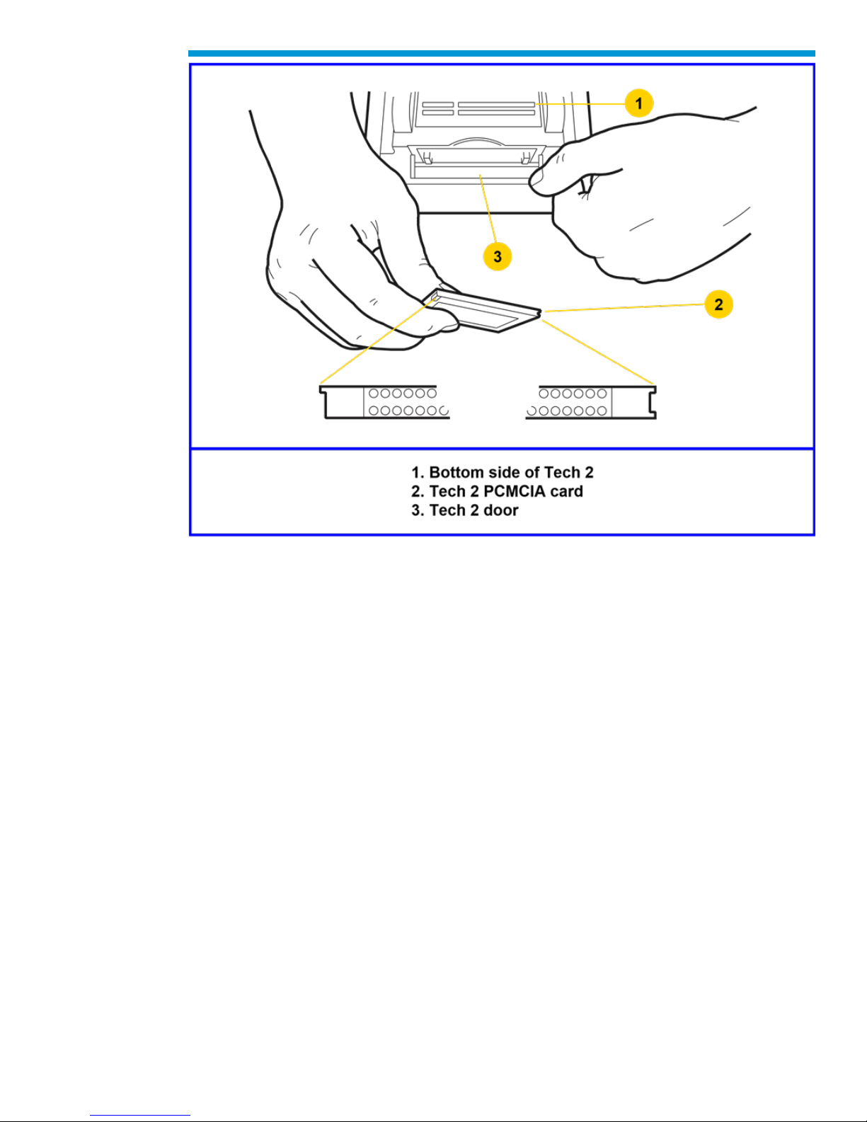
The PCMCIA Card is keyed with two notches on one side and one notch on the other side.
Make sure that the notches are in the correct position before inserting the card. Slowly
insert the card until it clicks into place.
23
Page 24
General Motors Tech2 User Guide
PCMCIA card keying
24
Page 25
General Motors Tech2 User Guide
PCMCIA card insertion
Notice: Use only GM Service and Parts Operations supplied PCMCIA cards. The
PCMCIA slots are designed to interface with 5-volts cards. Permanent damage to Tech2
could occur if a 3.3-volt card is inserted into the Tech2 PCMCIA connector.
Vehicle Communications Interface Module Removal
The Vehicle Communications Interface (VCI) module is located at the lower end of the
Tech2. Removal of this module is required only if the VCI needs to be updated or replaced.
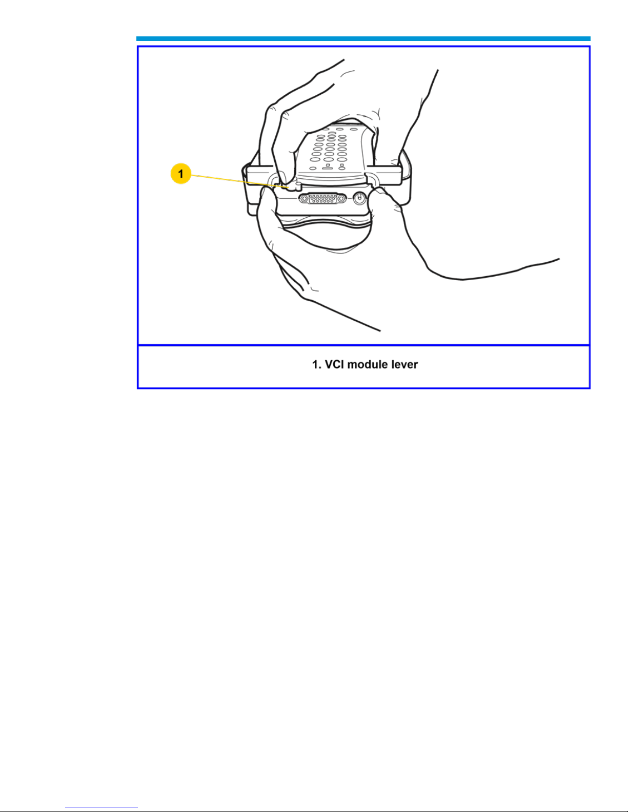
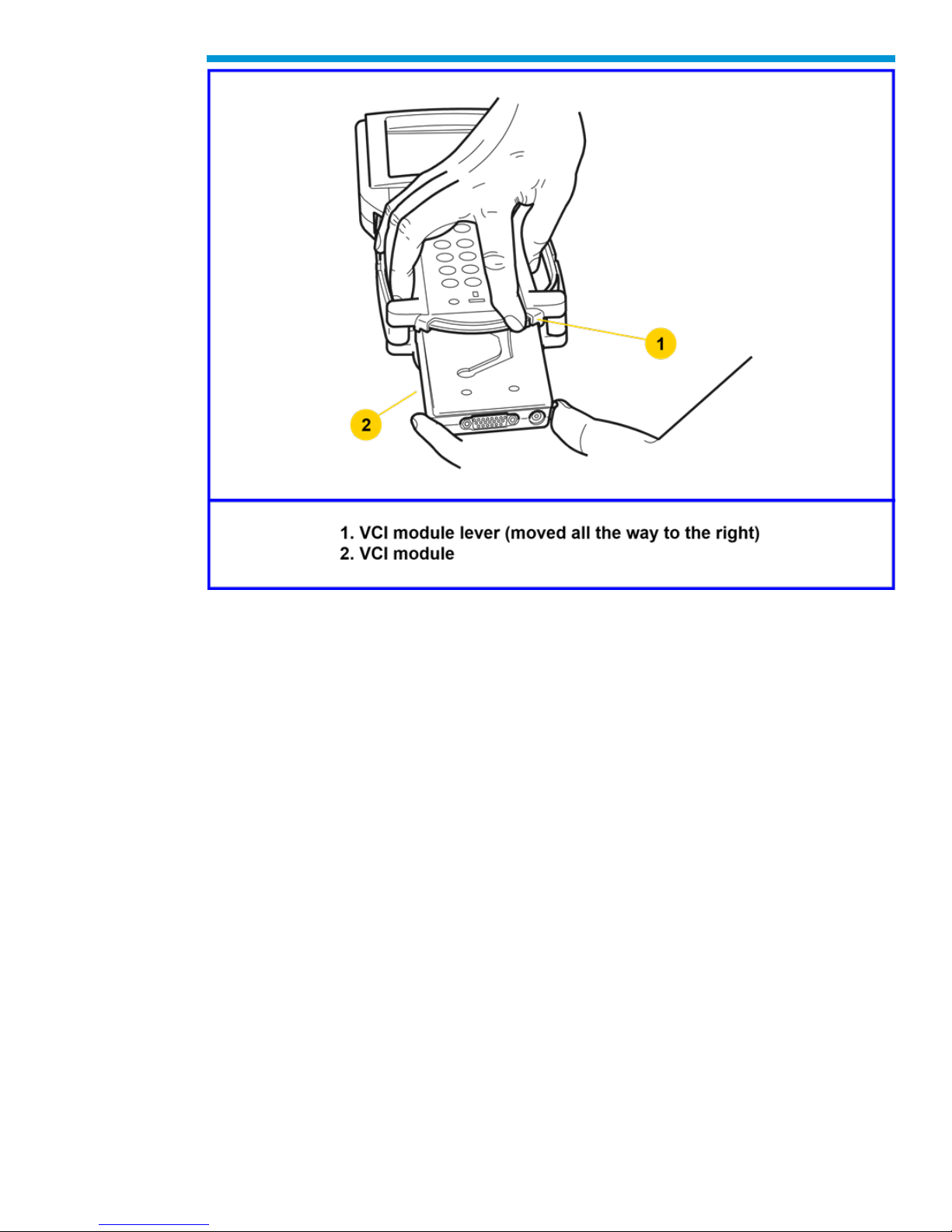
To remove the module disconnect Tech2 DLC cable if attached, move the lever all the way
toward the right side of the Tech2. The VCI module can now be removed.
25
Page 26
General Motors Tech2 User Guide
VCI module removal
26
Page 27
General Motors Tech2 User Guide
VCI module removed
Hand Strap Adjustment
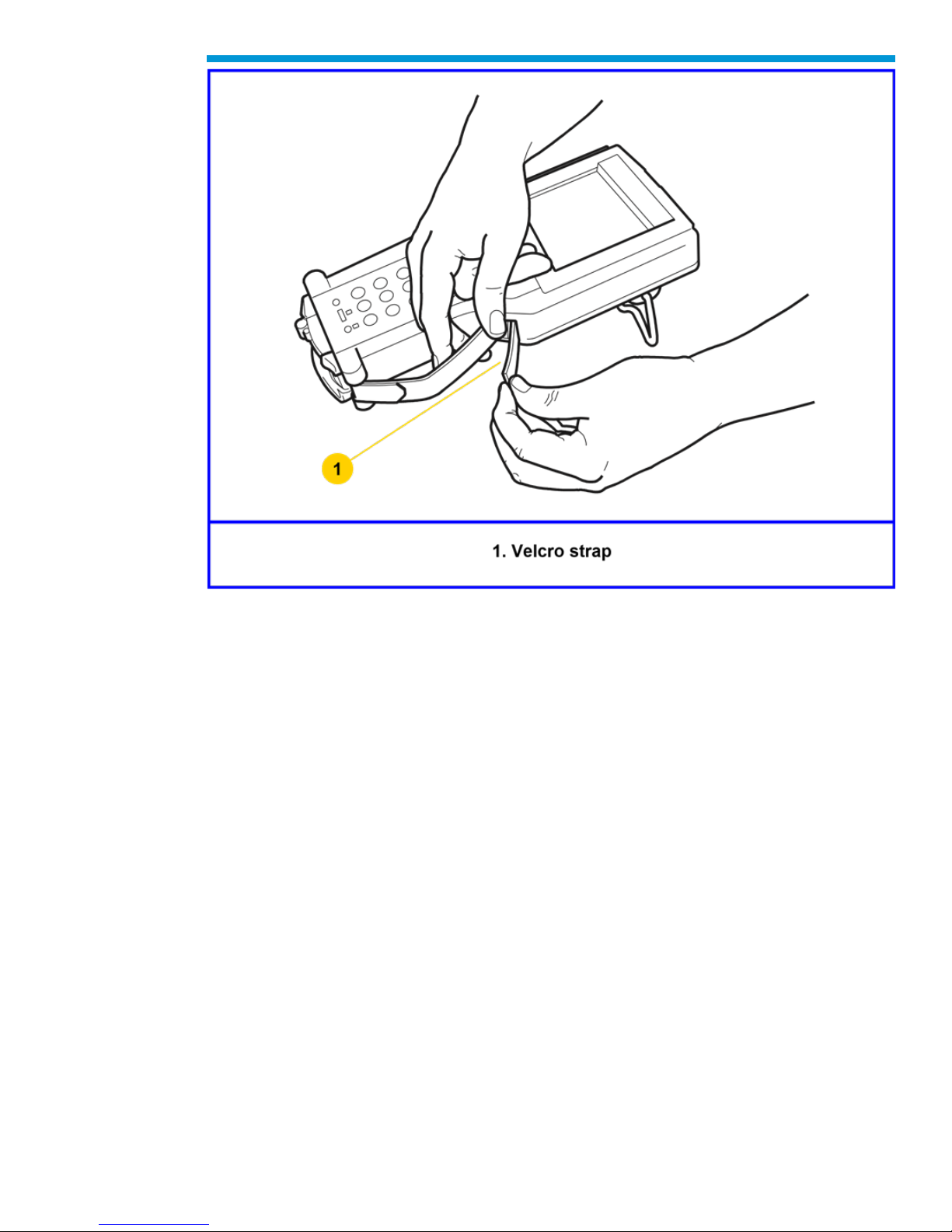
The Tech2 velcro hand straps may be adjusted for individual needs as shown in the
illustration below.
27
Page 28
General Motors Tech2 User Guide
Tech2 hand strap adjustment
Tech2 Keypad
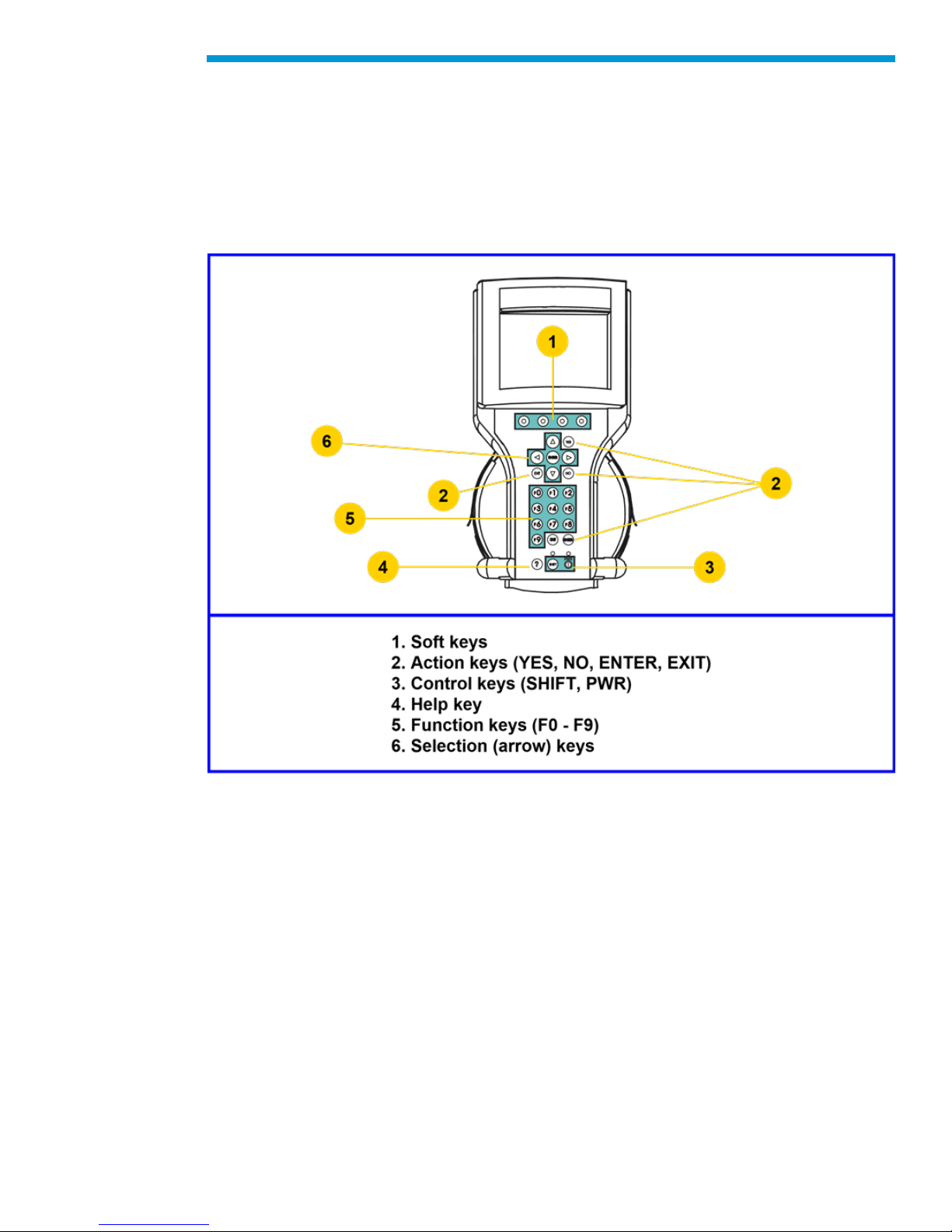
The Tech2 keypad consists of six major keypad operation areas:
1. Control keys (SHIFT, PWR)
2. Soft keys
3. Selection (arrow) keys
4. Action keys (YES, NO, ENTER, EXIT)
5. Function keys (F0 to F9)
6. Help (?) key
Control Keys
The [PWR] key is used to turn the Tech2 on or off. The status indicator light above this key
will be illuminated green when the Tech2 is operational.
The [SHIFT] key is used with the up and down arrow keys to change screen brightness
and contrast. To adjust screen brightness and contrast, perform the following:
• Press the [SHIFT] key once (amber status indicator light above [SHIFT] should light
up).
28
Page 29
General Motors Tech2 User Guide
• Use up and down arrows to adjust screen brightness and contrast: Press up arrow
key to increase screen brightness and contrast.
Press down arrow key to decrease screen brightness and contrast.
• Press [SHIFT] key again when desired brightness is reached (status indicator light
above [SHIFT] should now be off).
The Tech2 should return to normal operation after following the above steps.
Tech2 keypad Location of control keys
Soft Keys
Four soft keys are located directly below the Tech2 screen. The soft keys correspond
directly to the four possible selection boxes found at the bottom region of the Tech2
screen. These selections may change from screen to screen and are under the control of
the application software. To make a screen selection, press the corresponding soft key. In
the example shown, the first soft key was pressed to select [Display Time].
Selection Keys
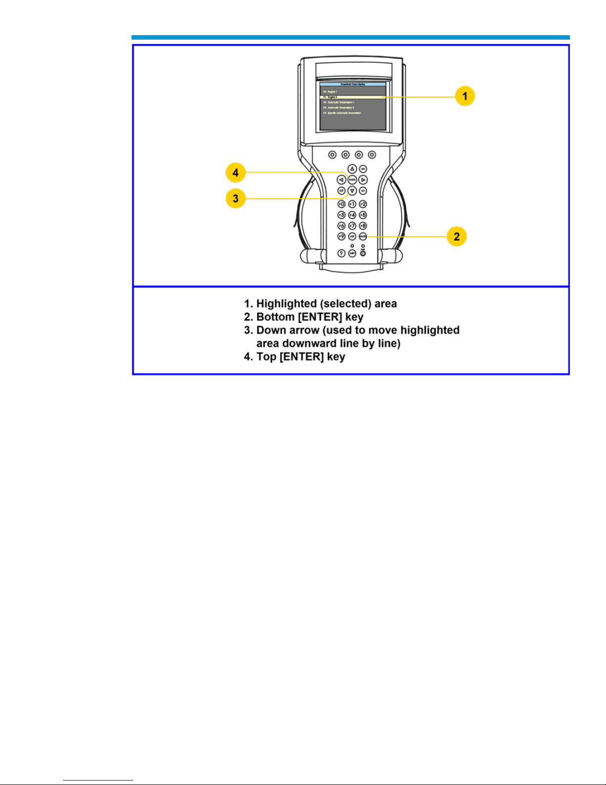
The Tech2 selection keys are four directional arrow keys. Press the arrow keys to move
the highlighted area to a selection on the screen or to scroll the screens if more than one.
Once the desired selection is highlighted, press [ENTER] to activate the selection.
29
Page 30
General Motors Tech2 User Guide
Action Keys
Action keys are used to respond to a specific question, initiate an action, or to exit from the
Tech2 program. Specific “yes or no” questions will often appear on the Tech2 screen. The
[YES] and [NO] keys are used to respond to these questions. Either of the two [ENTER]
keys may be pressed to activate a menu selection. Either of the two [EXIT] keys may be
pressed to leave the current Tech2 screen and return to a previous screen.
Function Keys
Ten function keys (F0 to F9) are located on the Tech2 keypad. A function key may be
pressed to initiate a specific Tech2 function. In some cases the function keys are used for
numeric data entry. The arrow keys and [ENTER] may also be used to initiate a function
selection, but this will require multiple keystrokes as opposed to only one.
Help Key
The help key [?] may be pressed at any time to obtain a help screen. The help screen will
provide specific information relating to the operation of the Tech2.
30
Page 31
General Motors Tech2 User Guide
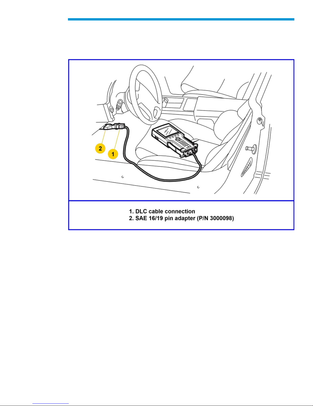
Tech2 Connection to Vehicle
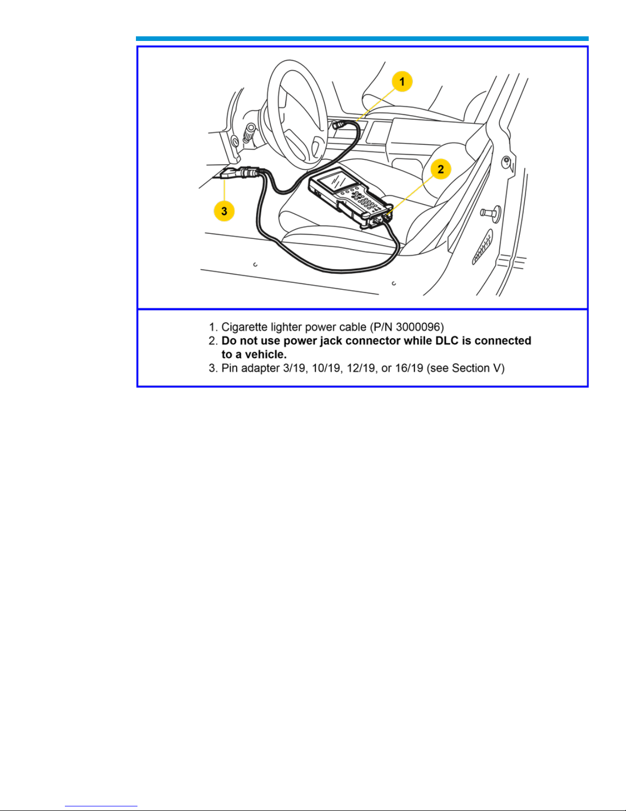
The Tech2 receives power through the DLC cable connection to vehicles equipped with
On-Board Diagnostics (OBD II). In the case of vehicles not equipped with OBD II, an
external power source such as a vehicle cigarette lighter must be used.
Attaching the Tech2 to OBD II equipped vehicles
31
Page 32
General Motors Tech2 User Guide
Attaching the Tech2 to non-OBD II equipped vehicles
32
Page 33
General Motors Tech2 User Guide
Tech2 Connection to TIS2Web Computer
At times the Tech2 will need to be connected to a computer. Reasons for connection to a
computer include the following:
• Transfer of vehicle data (calibration information, “snapshot,” etc.) from the Tech2 to
the computer
• Transfer of vehicle calibration data from the computer to the Tech2
• Transfer of data (software update, etc.) from the computer to the Tech2
Before connecting Tech2 to the computer, the following steps should be taken:
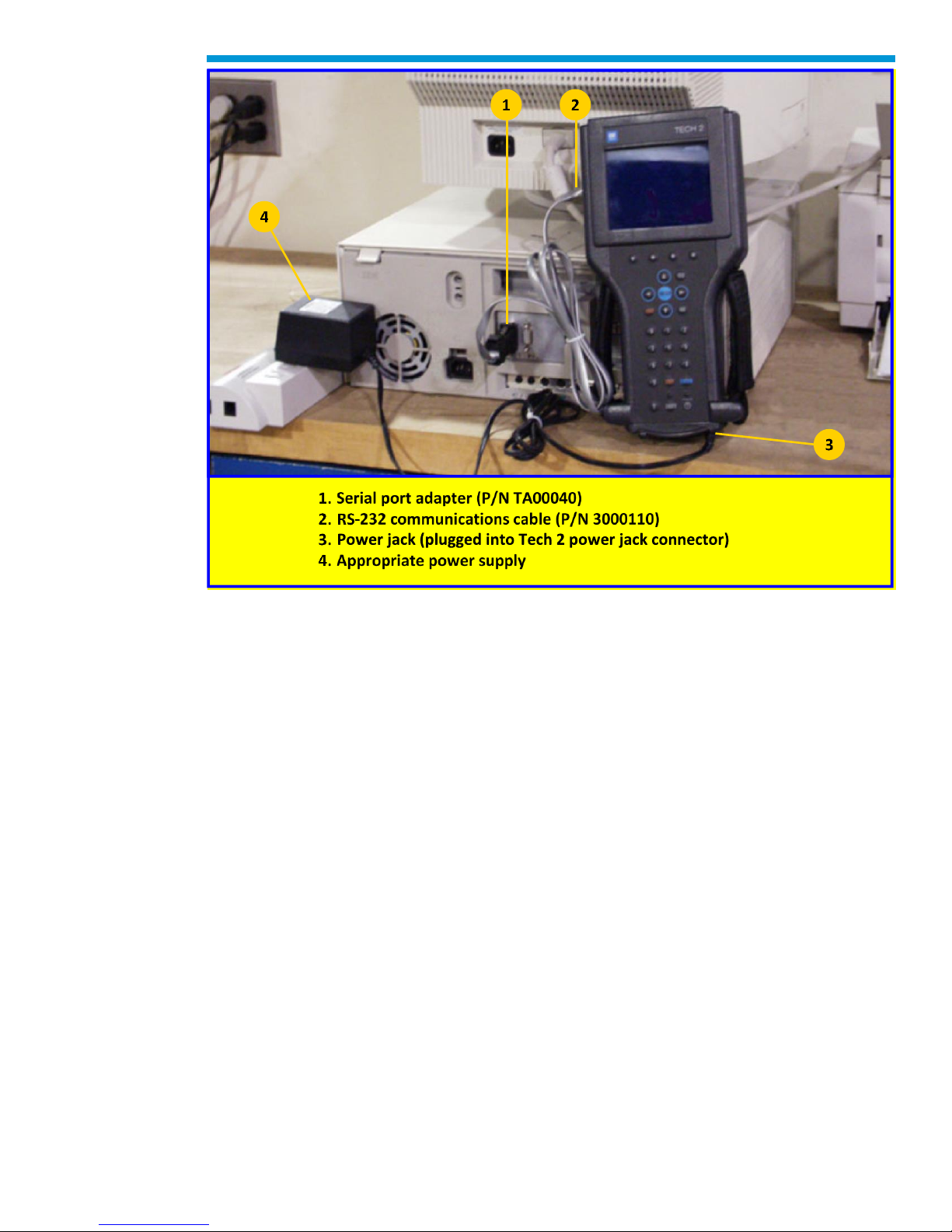
• Make sure the RS-232 cable (P/N 3000110) is attached to the Tech2 RS-232 port
located on the left side of the Tech2.
• Make sure the appropriate power supply is connected to the DLC cable power jack
connector, or to the power jack connector at the bottom of the Tech2.
• Make sure the PCMCIA card is fully inserted into the upper slot at the top of the
Tech2.
• Make sure the CANdi module is not connected to the Tech2.
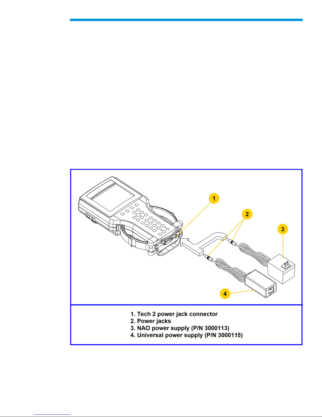
Power supply connections for communication with the computer.
33
Page 34
General Motors Tech2 User Guide
Notice: Always use the Tech2 NAO power supply (P/N 300113) when connecting the
Tech2 to a computer. It is also acceptable to connect the power cable to the vehicle
cigarette lighter.
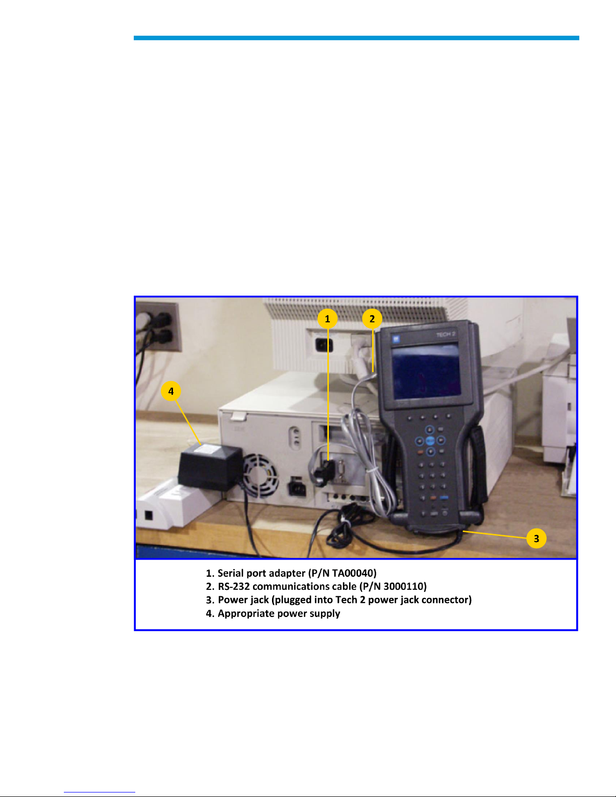
How to Connect the Tech2 to a Computer
Follow the steps below for the typical Tech2 connection to a computer.
1. Plug the serial port adapter (P/N TA00040) into the serial port marked “A” or “1” on the
back of the computer or to the USB port using the USB serial adapter.
2. Plug the Tech2’s RS-232 cable into the serial port / USB port adapter and connect the
appropriate power supply.
3. After power is supplied to the Tech2 and the [PWR] button is pressed, the Tech2 startup display should appear on the Tech2 screen.
Note: Not all USB to serial port adapters are compatible with the Tech2. ACDelco
recommends using the Keyspan brand USB to serial port adapter.
Typical Tech2 connection to a computer (rear view)
34
Page 35
General Motors Tech2 User Guide
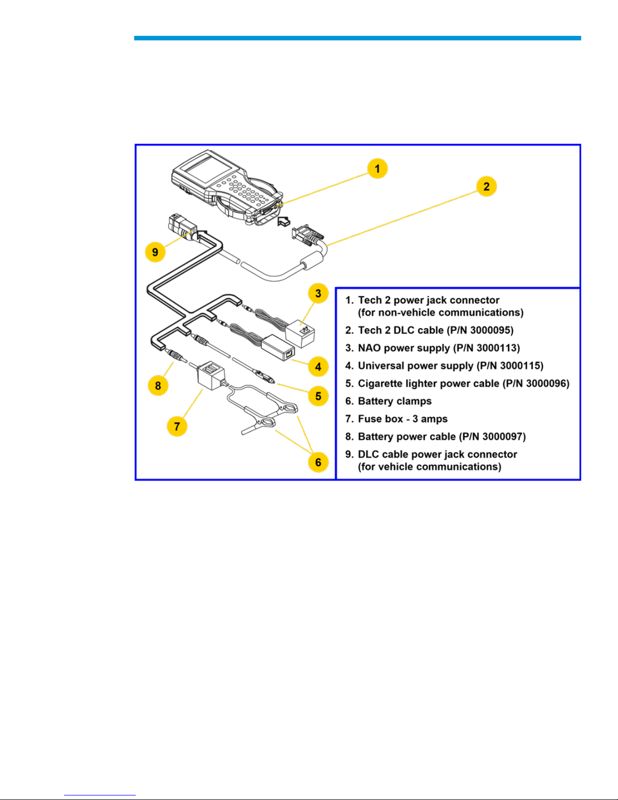
Power Supplies
Power up the Tech2 using either:
• The power jack connector at the bottom of the Tech2 unit, or
• The DLC cable power jack connector behind the area where various DLC adapters are
connected.
For non-vehicle communications, connect power source to either location.
For vehicle communications, connect the power source to the DLC cable power jack
connector only. Proper grounding may not be present if power source is connected directly
to Tech2.
When the Tech2 is connected to the DLC of an appropriate vehicle, the vehicle battery
supplies power. When the Tech2 is not connected to the vehicle’s DLC, the DLC cable
power jack connector accepts power from the following:
• Cigarette lighter power cable
• Battery power cable
• NAO or Universal power supply
If the DLC and external power source are both connected, the power jack connection
supplies current to the Tech2. In this instance, power from the vehicle’s DLC connector is
automatically disconnected from the Tech2 internal power supply.
35
Page 36

General Motors Tech2 User Guide
Cigarette Lighter Power Cable
This cable contains one fuse and two connectors. It has a cigarette lighter plug at one end
and a power jack at the other. The power jack connects to the Tech2 DLC cable and
carries power to the Tech2 when the selected vehicle adapter does not provide power.
Battery Power Cable
This cable has red and black battery clamps attached to one end and a power jack
attached to the other. The power jack connects to the Tech2 DLC cable and carries current
to the Tech2 when the selected vehicle adapter does not provide power and there is no
cigarette lighter adapter available.
Important: This cable contains two 3-amp fuses. If you need to replace them, use identical
3-amp fuses.
For information on fuse replacement, see Troubleshooting.
NAO Power Supply
North American electrical supply is normally 110 volts. The Tech2 base kit includes an
external AC to DC power supply with 110 V AC/60 Hz input. Output is 12 volts at 1.5 amps.
Universal Power Supply
Wherever 220 current is required, use the 110/220 V AC/50 Hz external AC to DC power
supply. A specific power cord is provided to permit connection to your area’s power cord
receptacle.
CAUTION: To avoid personal injury due to electric shock, use grounded outlet only. The
NAO power supply is for North American use only. The Universal power supply is for use
outside North America. These devices are intended for indoor use only.
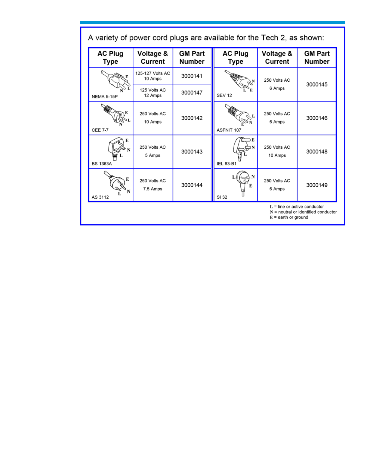
Power Cord Plugs
Various types of power cord plugs are available for the Tech2, depending your geographic
location.
36
Page 37
General Motors Tech2 User Guide
Table showing various types of power cord plugs for the Tech2
37
Page 38
General Motors Tech2 User Guide
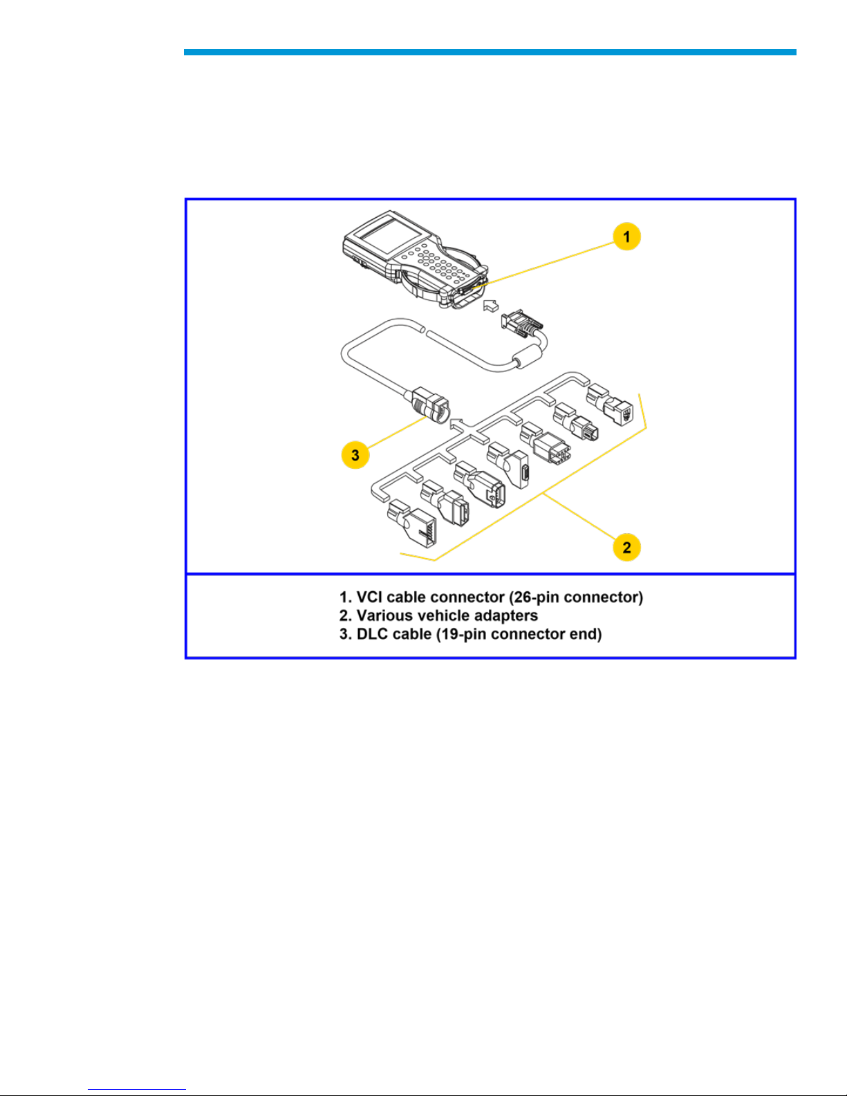
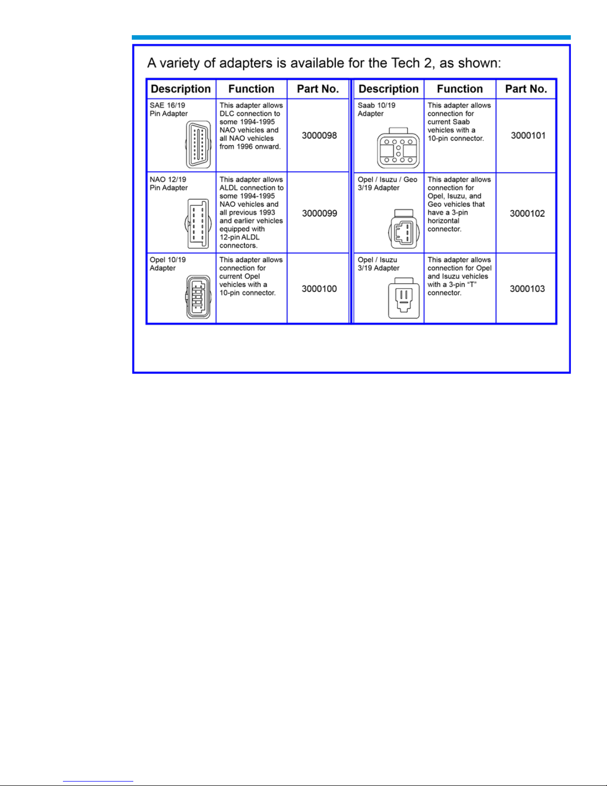
Adapters
A number of adapters are available for the Tech2 which allow connection to many different
vehicles. Specific adapters are included in the Tech2 base kit depending upon Tech2
configuration—NAO, International, Saab, Opel, Vauxhall, etc. Adapters not included in the
base kit may be purchased separately from your tool distributor.
DLC Cable
The DLC cable (P/N 3000095) has a 26-pin connector with thumb screws at one end that
connects to the Tech2’s VCI cable connector. At the other end is a 19-pin connector that
connects to a variety of adapters.
38
Page 39
General Motors Tech2 User Guide
RS-232 Cable
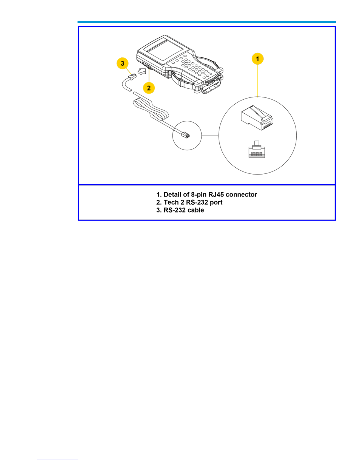
The RS-232 cable (P/N 3000110) has an 8-pin RJ45 plug connector at each end. This
cable attaches to the Tech2 RS-232 port and is used to communicate with the TIS2Web
computer.
39
Page 40
General Motors Tech2 User Guide
RS-232 cable connections
40
Page 41

General Motors Tech2 User Guide
RS-232 DB9 Adapter
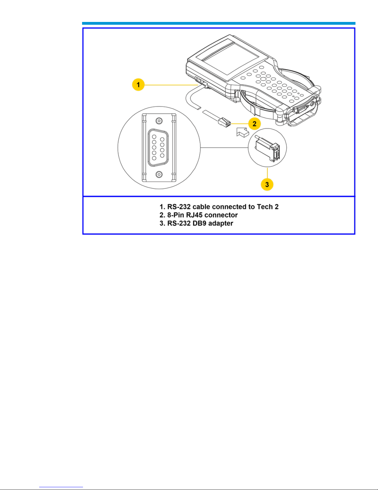
The RS-232 DB9 adapter (P/N 3000111) has an RJ45 connector at one end and a DB9
connector at the other. This adapter allows the connection of the Tech2 to some
computers.
41
Page 42
General Motors Tech2 User Guide
RS-232 DB9 adapter connections
RS-232 Loopback Adapter
The loopback adapter (P/N 3000112) has an 8-pin RJ45 connector that attaches to the
Tech2 RS-232 port. It is used to perform the Tech2 self test.
DLC Loopback Adapter
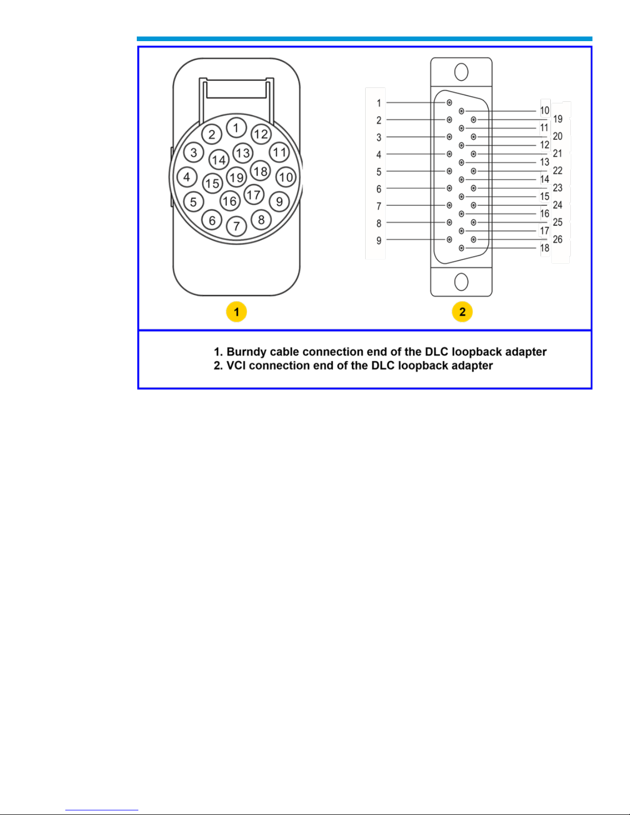
Various Tech2 applications require the DLC loopback adapter (P/N 3000109), which has a
Burndy cable connection end and a VCI DB-26 connection end.
42
Page 43
General Motors Tech2 User Guide
End views of the DLC loopback adapter
USB to Serial Port Adapter
Not all USB to serial port adapters are compatible with the Tech2. ACDelco recommends
using the Keyspan brand USB to serial port adapter.
43
Page 44
General Motors Tech2 User Guide
Typical Tech2 connection to a computer (rear view)
Troubleshooting
This is a general troubleshooting guide for all vehicle applications of the Tech2 scan tool.
Some of the information may differ for your particular vehicle application.
If the Tech2 appears to be operating abnormally, refer to this section—particularly the
diagnostic charts and troubleshooting tables—for probable causes and solutions.
The following two types of self tests are available on the Tech2:
• Power On Self Test (POST) checks the major functions of the Tech2 at power-up.
• Self Tests check the major and minor functions of the Tech2.
If errors are detected, a Tech2 malfunction is present which may result in vehicle
misdiagnosis.
For customer support, refer to the Customer Support Overview on pages ii and iii of this
user’s guide.
Notice: The CANdi module should not be connected while running Tech2 and VCI self
tests.
44
Page 45

General Motors Tech2 User Guide
Power On Self Test (POST)
Power On Self Tests run automatically each time the power [PWR] button on the Tech2
keypad is pressed on. The screen displays pass or fail results for each area tested. POST
automatically checks the following:
• MC68332 processor
• External RAM (Random Access Memory)
• Flash memory
• Display controller and display
• Sound transducer
• MC68332 RAM
• Real-time clock
• Keypad controller and keypad
• Main UART (Universal Asynchronous Receiver/Transmitter)
Results of POST may include fatal errors that do not allow you to continue, or non-fatal
errors that allow you to continue without full Tech2 operation. If normal Tech2 functions are
stopped or limited, contact Customer Support to determine if service is required.
At completion of POST, the following audible signals indicate a pass or fail condition:
• One beep - No problem. Your Tech2 is operating normally.
• No beep - Sound transducer has failed. Contact Customer Support.
• Three short beeps - Tech2 has failed POST. Contact Customer Support.
In the United States and Canada to contact the ACDelco Aftermarket Support Center, dial
1.888.212.8959.
Tech2 Self Tests
Tech2 self tests verify that the Tech2 is functioning normally. The self tests evaluate all
critical areas of the Tech2 and display pass or fail messages for each subsystem tested.
Self tests isolate user error from system hardware failures. The self tests should be
performed periodically to insure that the Tech2 is operating properly.
The Tech2 must meet the following requirements in order to do a self test:
• Screen display must be fully readable
• Keypad must be operational
Begin the Tech2 self-testing program by following these steps:
1. Press [ENTER] while viewing the Tech2 start-up screen.
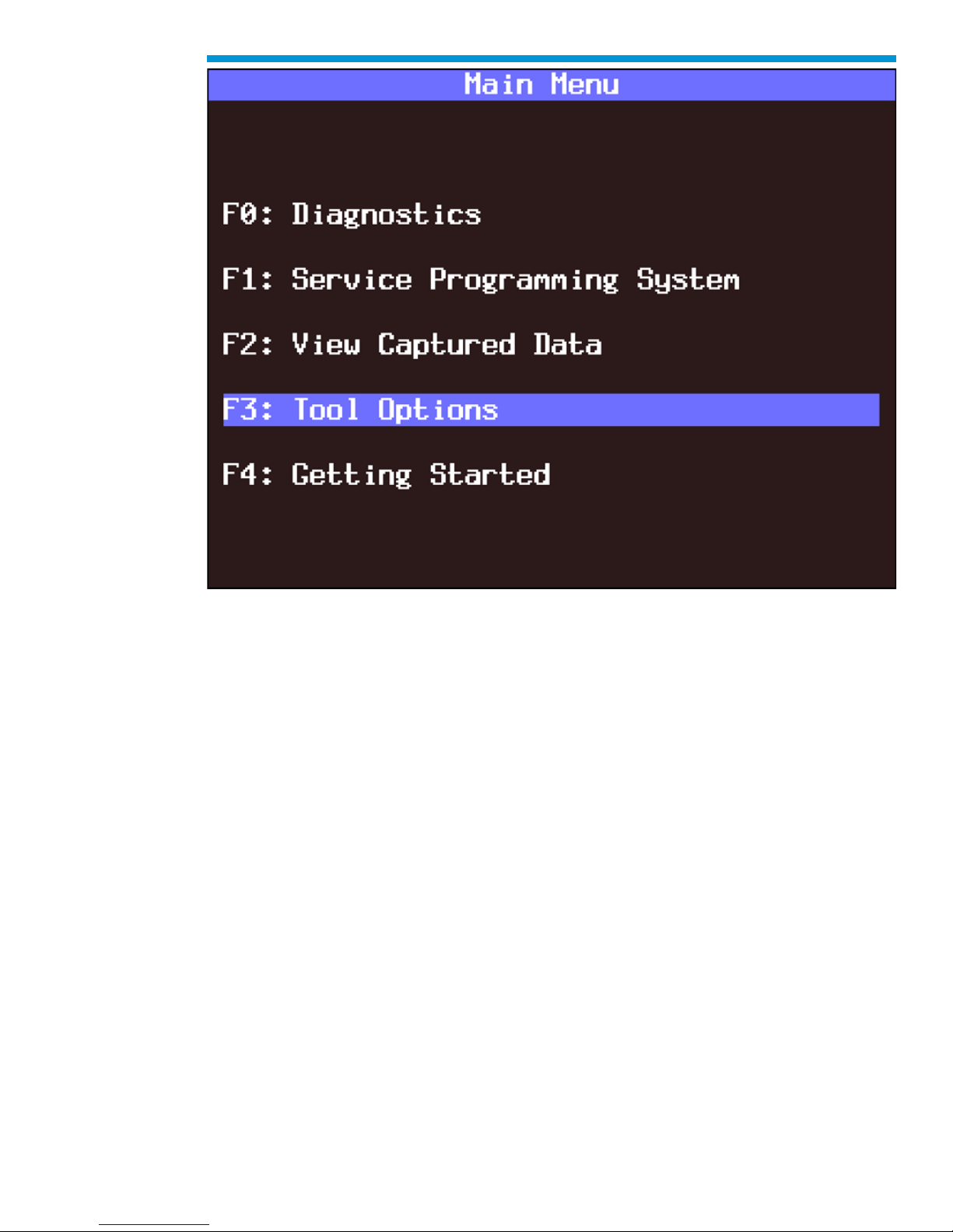
2. Select F3: Tool Options from the Tech2 Main Menu.
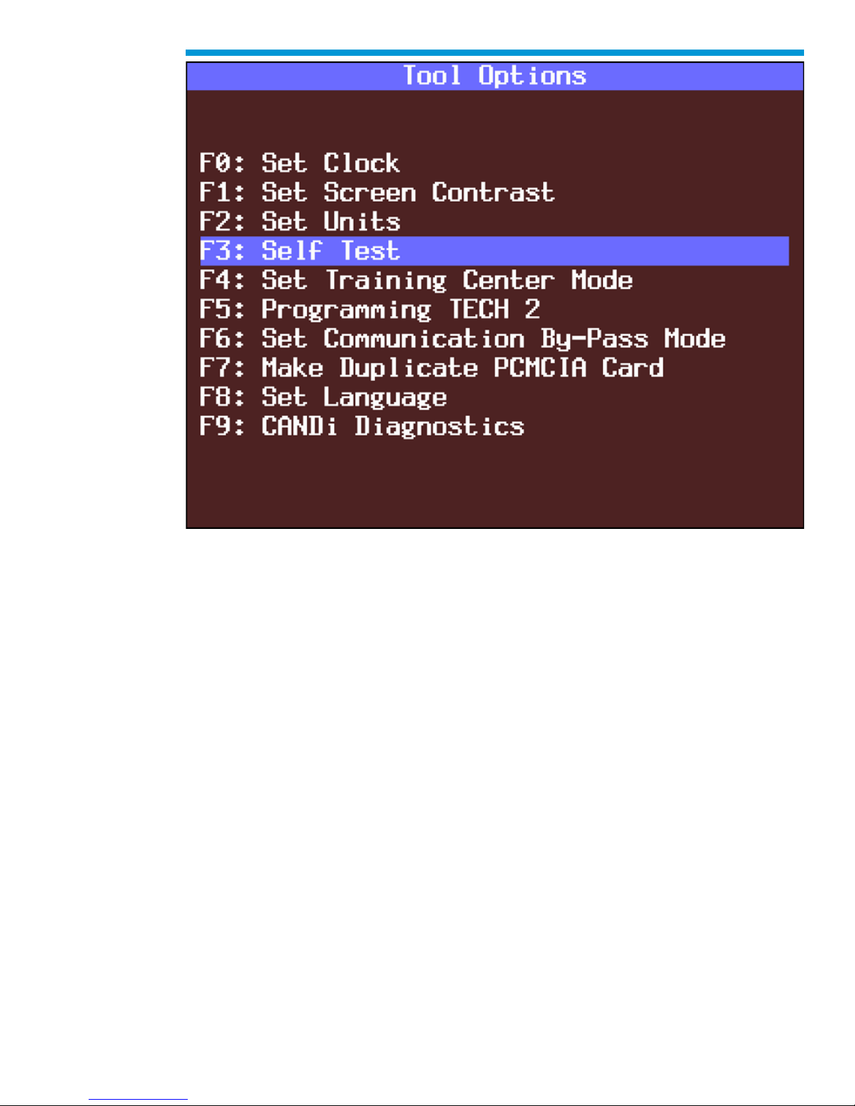
3. Select F3: Self Test from the Tool Options menu.
45
Page 46

General Motors Tech2 User Guide
Tech2 startup screen
46
Page 47
General Motors Tech2 User Guide
Tools Options selected on Main Menu
47
Page 48
General Motors Tech2 User Guide
Self Test selected on Tool Options menu
Tech2 Self Test Main Menu
Each Tech2 Self Test main menu selection is explained in detail on the following pages. All
users have access to all the options listed.
48
Page 49
General Motors Tech2 User Guide
Read all screen instructions and connect or disconnect the appropriate cables and
loopback adapters. Screen messages will be displayed when ex ternal loopback connectors
are connected.
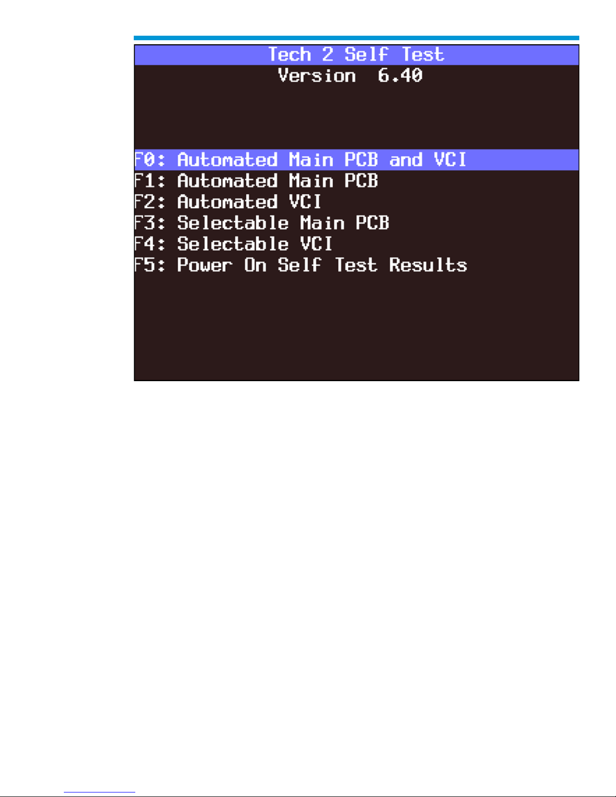
F0: Automated Main PCB and VCI Test
Selecting Automated Main PCB and VCI is a quick way to test the performance of the main
Printed Circuit Board (main PCB—the Tech2 main circuit board) and the Vehicle
Communications Interface (VCI). The Tech2 displays a test-in-progress screen while
performing all the PCB and VCI tests in sequential order.
49
Page 50
General Motors Tech2 User Guide
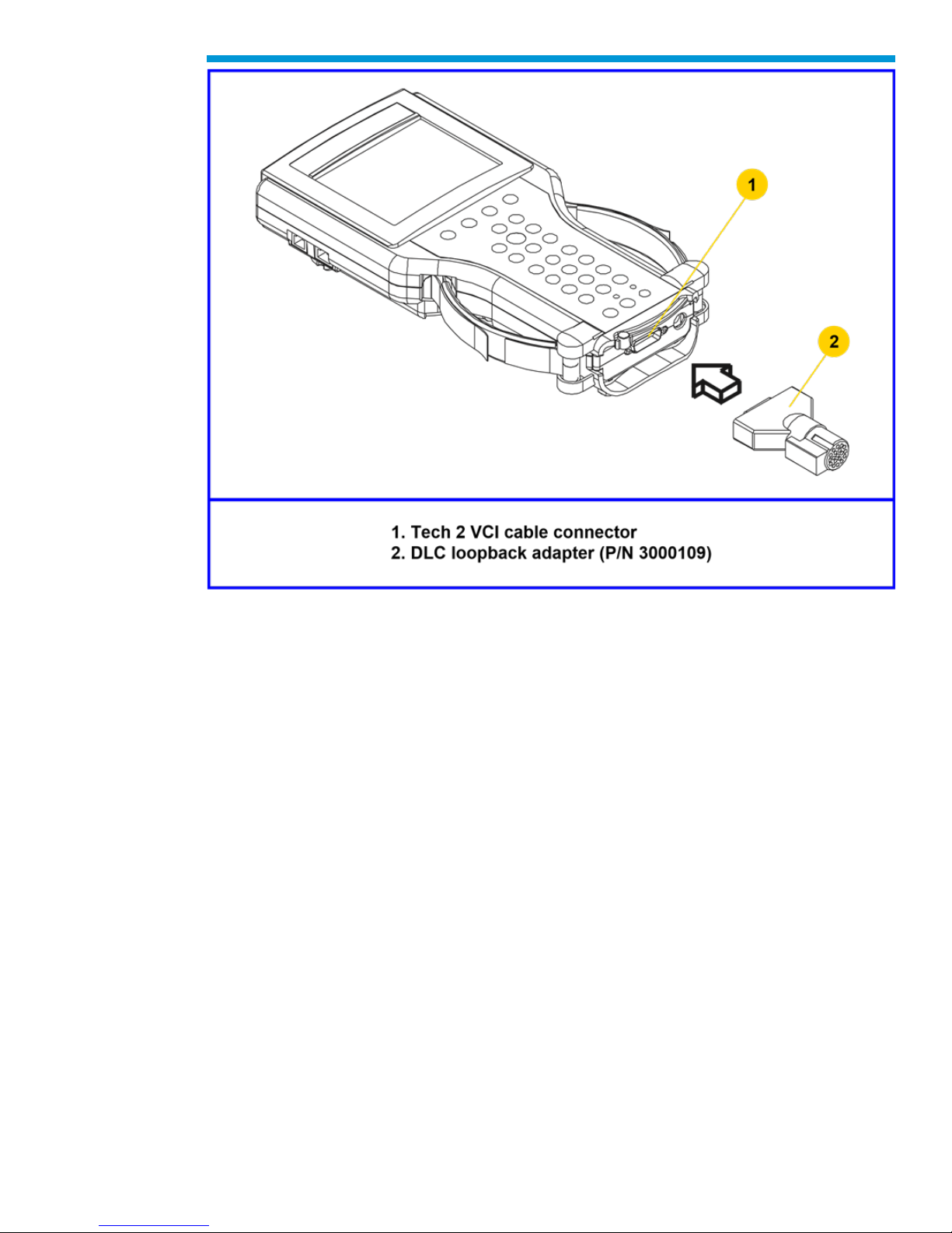
Connection of DLC loopback adapter to the Tech2 VCI connector
50
Page 51
General Motors Tech2 User Guide
Automated Main PCB and VCI test selected on Tech2 Self Test main menu
51
Page 52
General Motors Tech2 User Guide
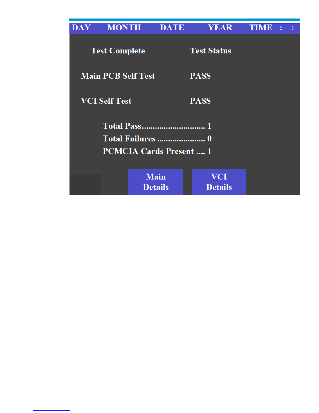
Test Status
52
Page 53
General Motors Tech2 User Guide
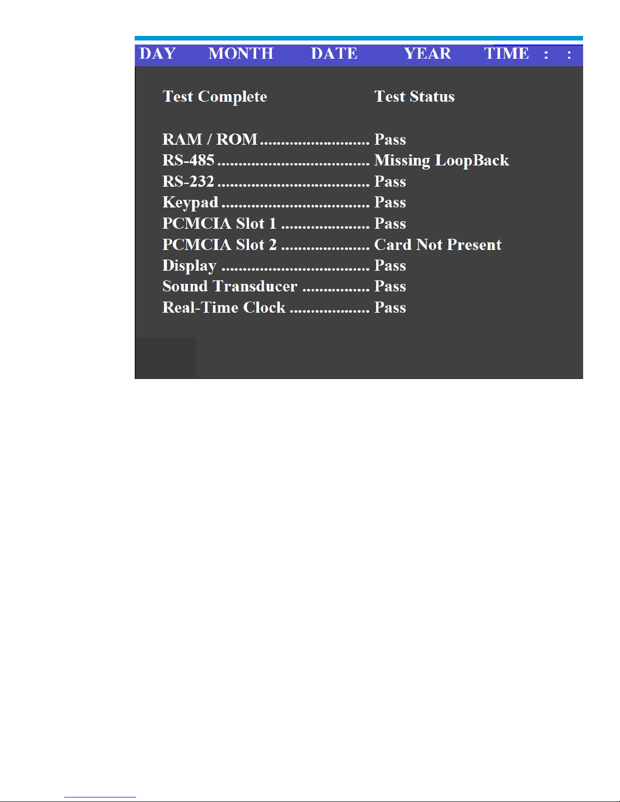
Test Pass
53
Page 54
General Motors Tech2 User Guide
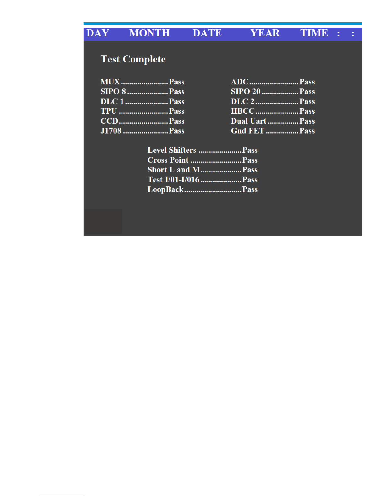
Test Complete
The Automated Main PCB portion tests the following components:
• RAM / ROM
• RS-485 loopback (This test requires the connection of a loopback adapter to the
Tech2.)
• RS-232 loopback (This test requires the connection of a loopback adapter to the
Tech2.)
• Keypad
• PCMCIA slot 1
• PCMCIA slot 2
• Display controller
• Sound transducer
• Real-time clock
If the Tech2 passes all Automated Main PCB and VCI tests, you will not need to run any
more tests to verify that the Tech2 is working properly.
The following test results will be displayed:
Total Pass................................ 1 - indicates that Tech2 passed test
0 - indicates a test failure
54
Page 55
General Motors Tech2 User Guide
Total Failures...........................0 - indicates that Tech2 passed test
1 - indicates a test failure
PCMCIA Cards Present...........1 or 2 indicates how many cards present in Tech2
Once tests are complete, select the soft keys Main Details or VCI Details to review the
results of the main PCB or VCI tests.
If any failures occur, select F3: Selectable Main PCB or F4: Selectable VCI from the Self
Test main menu to further isolate the failure. Report failure information to Customer
Support.
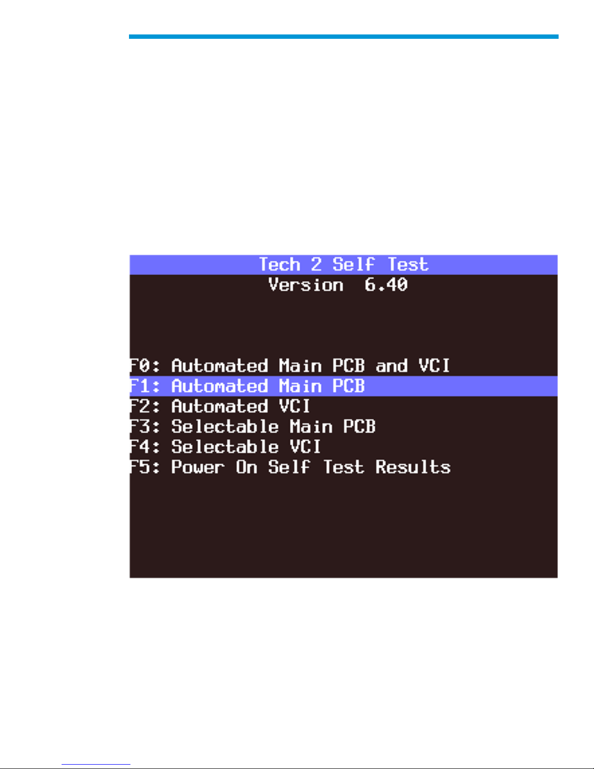
F1: Automated Main PCB Test
This test works the same as the Automated Main PCB and VCI test, except the VCI portion
of the test is not included.
F1: Automated Main PCB Test
55
Page 56
General Motors Tech2 User Guide
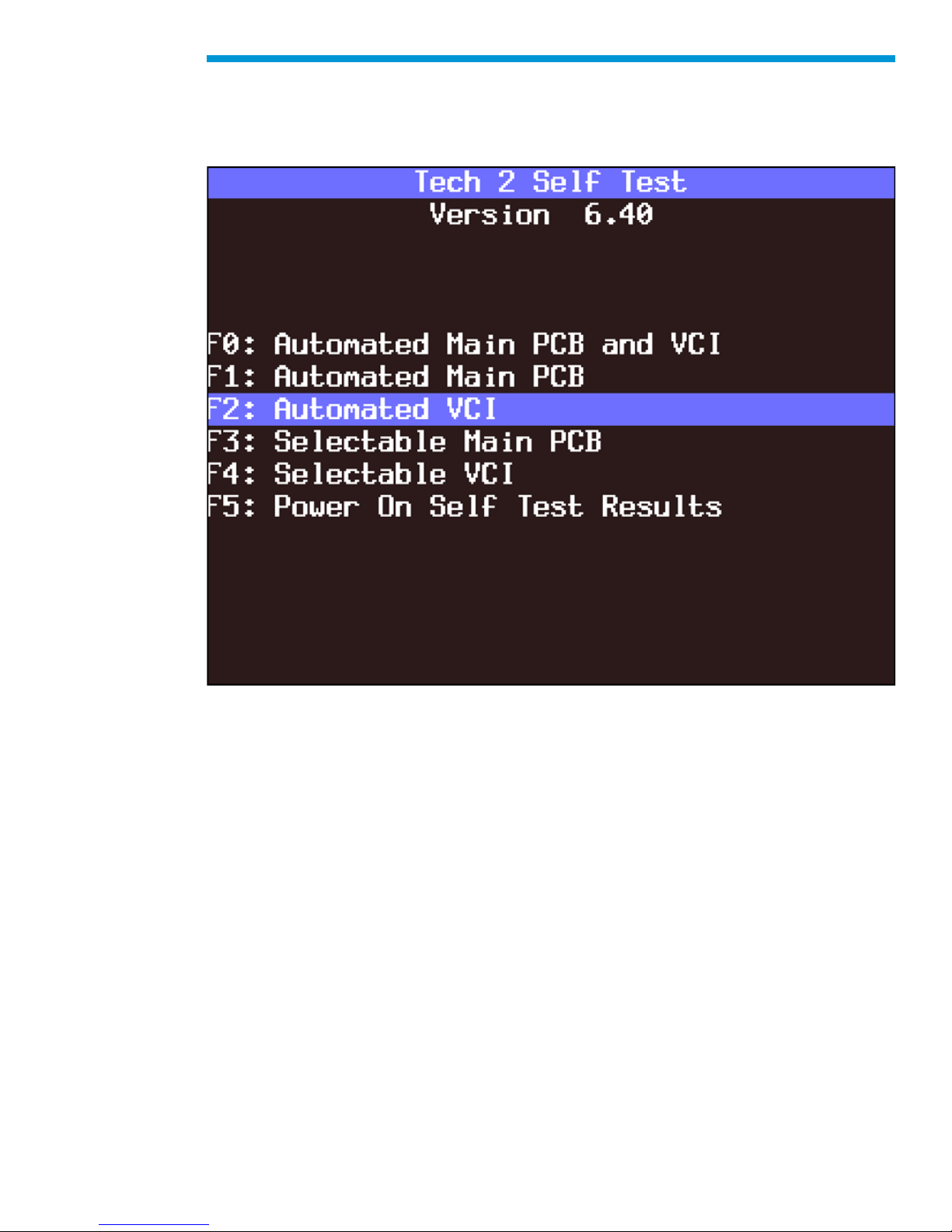
F2: Automated VCI Test
This test works the same as the Automated Main PCB and VCI test, except the PCB
portion of the test is not included.
F2: Automated VCI Test
56
Page 57

General Motors Tech2 User Guide
PCB Diagnostic Chart
Test
Results
Solution
RAM/ROM
0 – Pass
1 – ROM read fail
2 – RAM read fail
3 – RAM write and read do
not compare
Record type of failure.
Cycle Tech2 power (press
[PWR] and retest.
If problem persists, contact
Customer Support
RS-485
loopback
Pass
Fail – Loopback may not be
connected
Check loopback connection.
If problem persists, contact
Customer Support
RS-232
loopback
Pass
Fail – Loopback may not be
connected
Check loopback connection.
If problem persists, contact
Customer Support
Keypad
Test successful
Keypad failed
Exiting the test before all
keys are pressed results in a
failed keypad test.
Cycle Tech2 power and retest
If problem persists, contact
Customer Support
PCMCIA
(Tests both
card slots)
Card detected
Card not present
Fail
Check that card is inserted
properly.
Cycle Tech2 power and retest
If problem persists, contact
Customer Support
Display
controller
(Contrast and
Characters)
User determines if display is
correct.
If the display shows a noticeable
failure during tests, contact
Customer Support
Sound
transducer
User determines if
transducer is working
If no sound is emitted by
repeatedly selecting Automated
Test or Sound On, contact
Customer Support
Real-time
clock
Time is displayed correctly.
Invalid values are displayed
for date, year, hour, minute,
or second
Reset clock. Cycle Tech2
power and retest. If time is not
retained, contact Customer
Support
Diagnostic chart for Tech2 Main Printed Circuit Board (PCB)
57
Page 58

General Motors Tech2 User Guide
VCI MODULE DIAGNOSTIC CHART
Test
Results
Solution
MUX
(Multiplexer)
MUX A: S5 & S14
pass/fail
MUX B: S1 & S3
pass/fail
If MUX A or B fails, cycle
Tech2 power and retest. If
problem persists, contact
Customer Support.
VCI adapter ID
(performed only
during selectable
VCI test)
Recognized adapter
Cannot identify adapter
If adapter fails second
test, contact Customer
Support.
VCI ADC
(Analog to digital
converter)
Channel A - pass/fail
Channel B - pass/fail
If channel A or channel B
fail, cycle Tech2 and
retest. If problem persists,
contact Customer
Support.
Cross point
Pull up - pass/fail
TPU5, TPU1, and TPU0 -
pass/fail (results from selectable
VCI test)
If a failure occurs, cycle
Tech2 and retest.
If problem persists,
contact Customer
Support.
SIPO
(Serial In Parallel
Out)
Pass/fail for each area tested
If a failure occurs, cycle
Tech2 and retest. If
problem persists, contact
Customer Support
DLC
(Data Link
Connector)
DLC1 - DLC2
pass/fail count
DLC2 - DLC1
pass/fail count
If a failure occurs, cycle
Tech2 and retest.
If problem persists,
contact Customer
Support.
CCD
(Chrysler
Collision
Detection)
CCD - pass/fail
CCD - loopback not connected
Connect loopback and
retest if loopback not
connected. If test fails,
disregard results. Test is
not for GM vehicles (other
than Saab) at this time.
58
Page 59

General Motors Tech2 User Guide
VCI MODULE DIAGNOSTIC CHART (continued)
Test
Results
Solution
GND FET
(Ground Field
Effect Transistor)
GND FET – pass/fail
Check loopback adapter
to make sure it is
connected, cycle Tech2
and retest. If problem
persists, contact Customer
Support
VCI HBCC
(Hosted Bus
Control Chip)
HPCC – pass/fail
If HBCC chip fails, cycle
Tech2 and retest.
If problem persists,
contact Customer
Support.
VCI DUART
(Dual Universal
Asynchronous
Receiver
Transmitter
Channel A – pass/fail
Channel B – pass/fail
If channel A or channel B
fail, cycle Tech2 and
retest.
If problem persists,
contact Customer
Support.
VCI I/O 1 – I/O
16 Test
Pass/fail messages will be
displayed for each of the I/O
lines (results from selectable
VCI test).
If test fails, was loopback
installed?
Once an error has been
detected on one of the I/O
lines, you can test the
specific line by selecting
F3 or F4 tests. If the test
fails continuously or
intermittently, contact
Customer Support.
VCI loopback
Pass/fail message for each I/O
loopback test.
For any failure, make sure
the loopback is connected.
Use F1: Check ID to verify
that the loopback is found.
Cycle Tech2 and retest. If
problem persistes, contact
Customer Support
VCI short L&M
Open I/O 7 – pass/fail
Open I/O 9 – pass/fail
Hi I/O 7 – pass/fail
Hi I/O 9 – pass/fail
Lo I/O 7 – pass/fail
Lo I/O 9 – pass/fail
For any failure, cycle
Tech2 and retest. If
problem persists, contact
Customer Support.
59
Page 60

General Motors Tech2 User Guide
VCI MODULE DIAGNOSTIC CHART (continued)
Test
Results
Solution
VCI J1708
Internal transceiver – pass/fail
Differential – pass/fail
Differential – pass/fail (results
from selectable VCI test)
For any failure, cycle
Tech2 and retest.
If problem persists,
contact Customer
Support.
VCI TPU
(Time Processor
Unit)
TPU0 - pass/fail
TPU1 - pass/fail
TPU5 - pass/fail
TPU12 & TPU15 - pass/fail (or
not tested if
no loopback)
TPU13 & TPU14 - pass/fail (or
not tested if
no loopback)
For any failure, cycle
Tech2 and retest.
If problem persists,
contact Customer
Support.
VCI level shifters
MUX A 2.5 V Hi - pass/fail
MUX A 2.5 V Lo - pass/fail
MUX A 5.0 V Hi - pass/fail
MUX A 5.0 V Lo - pass/fail
(results from
selectable VCI test)
For any failure, cycle
Tech2 and retest.
If problem persists,
contact Customer
Support.
Diagnostic chart for Tech2 Vehicle Communications Interface (VCI) module
60
Page 61
General Motors Tech2 User Guide
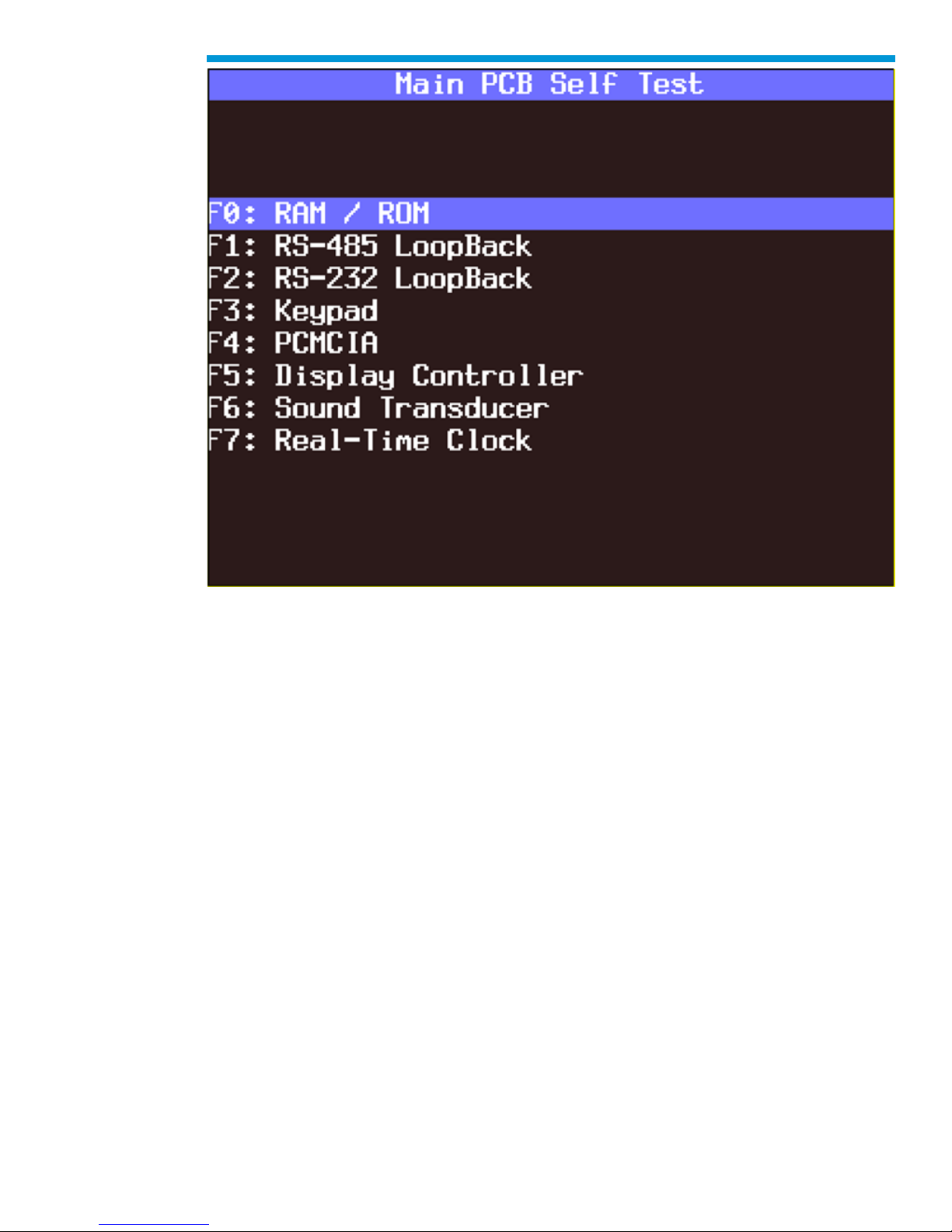
Automated Main PCB test selected on Tech2 Self Test main menu
61
Page 62
General Motors Tech2 User Guide
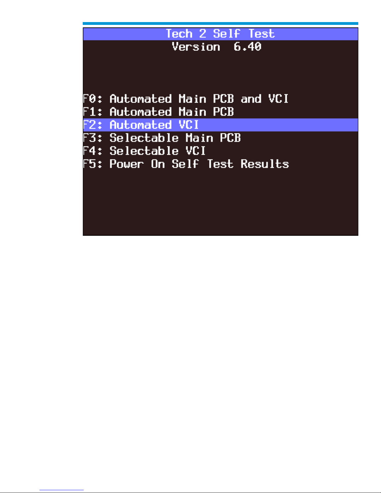
Automated VCI test selected on Tech2 Self Test main menu
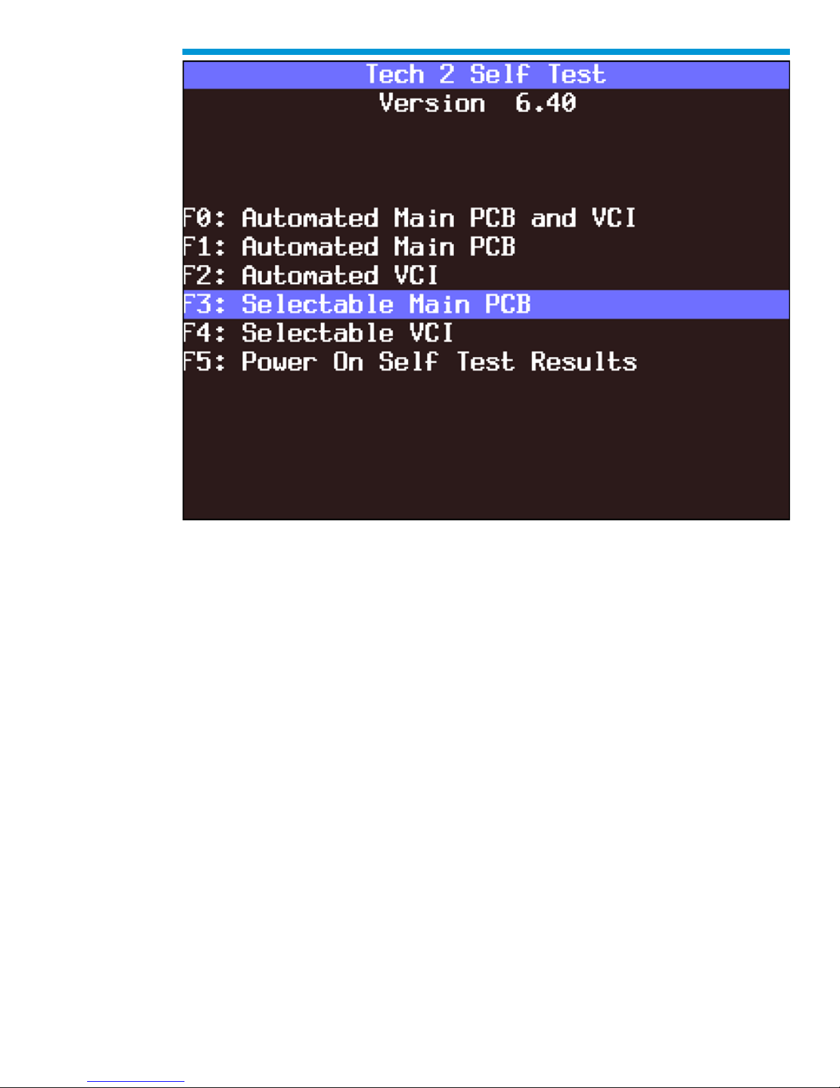
F3: Selectable Main PCB Test
Choose F3: Selectable Main PCB after a fail message has been displayed during the
Automated Main PCB and VCI or Automated Main PCB tests. When you choose F3:
Selectable Main PCB, a screen like the one shown in is displayed. You may then select
individual tests for failed components. For specific information on failed components, refer
to the Main Printed Circuit Board (PCB) Diagnostic Chart.
62
Page 63
General Motors Tech2 User Guide
Selectable Main PCB test selected on Tech2 Self Test main menu
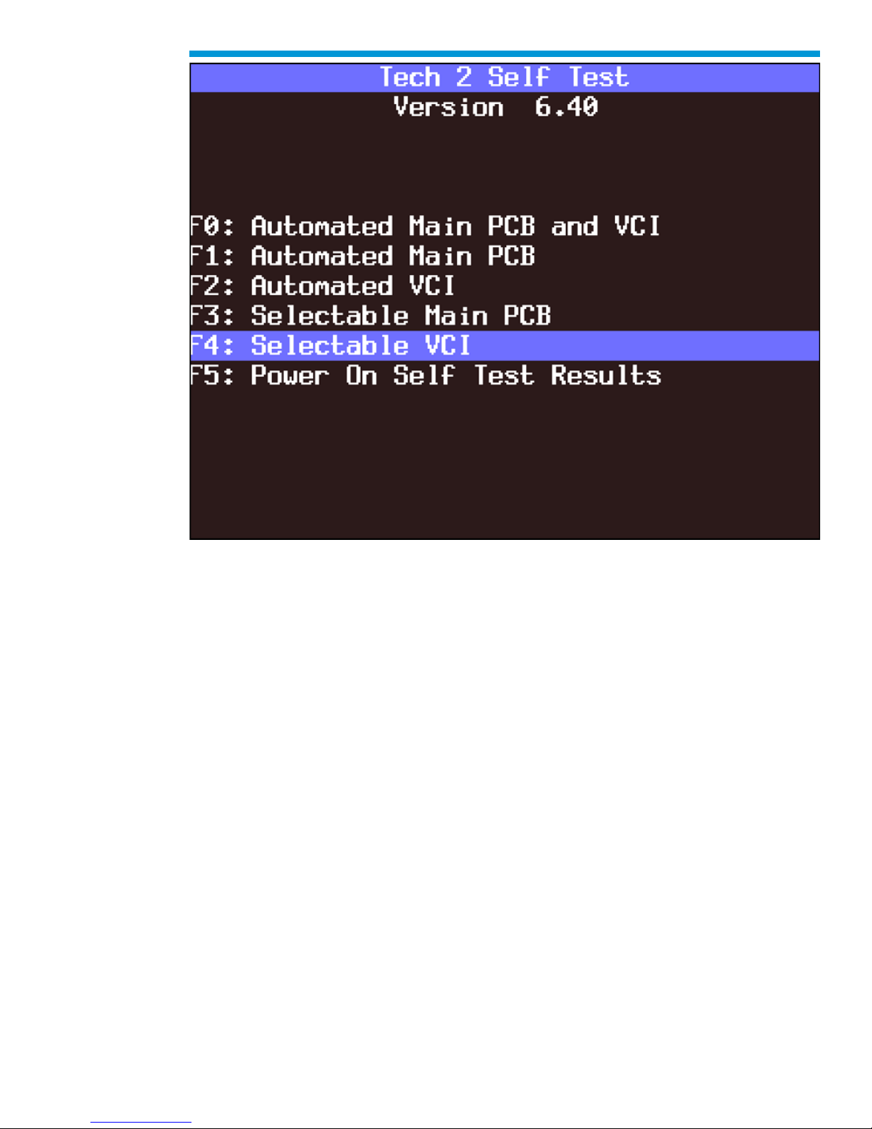
F4: Selectable VCI Test
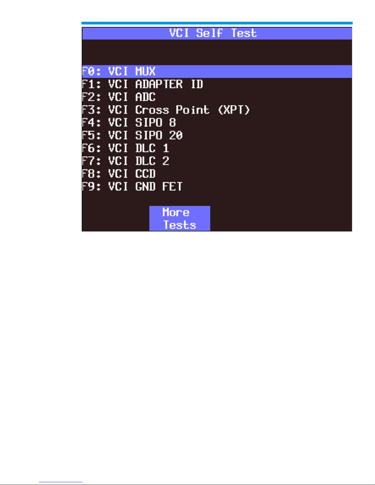
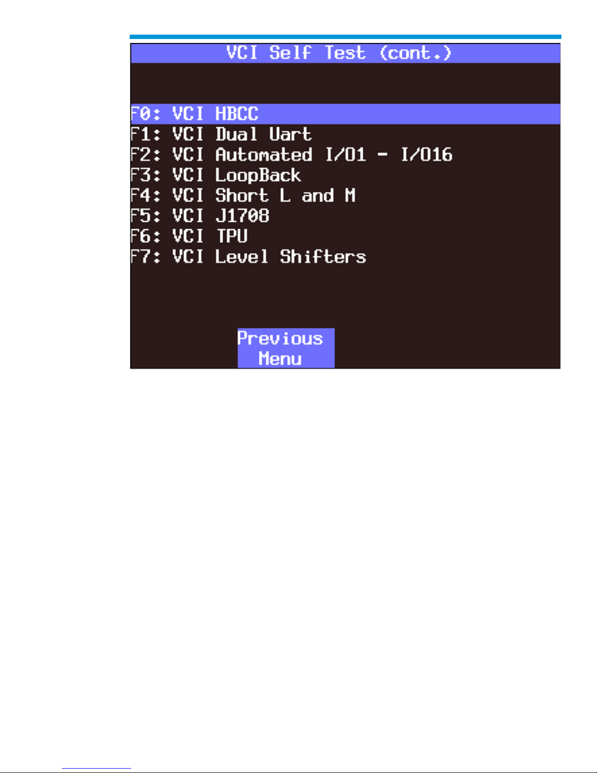
Choose F4: Selectable VCI after a fail message has been displayed during the Automated
Main PCB and VCI or Automated VCI tests. When you choose F4: Selectable VCI, a
screen is displayed where you may select individual tests for failed components. For
specific information on failed components, refer to the Vehicle Communications Interface
(VCI) Module Diagnostic Chart.
63
Page 64
General Motors Tech2 User Guide
Selectable VCI test selected on Tech2 Self Test main menu
64
Page 65
General Motors Tech2 User Guide
First selectable VCI Self Test screen
65
Page 66
General Motors Tech2 User Guide
Second selectable VCI Self Test screen
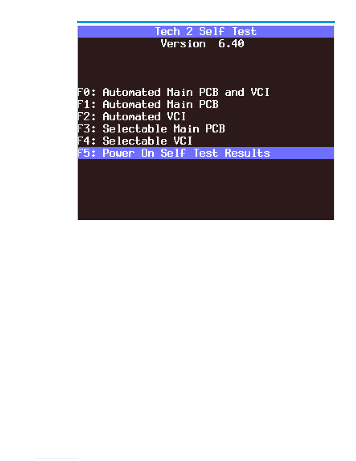
F5: Power On Self Test Results
Choose F5: Power On Self Test Results after a fail message has been displayed during
the Power On Self Test (POST). Specific information on the failure will be displayed on the
screen. Select F0, F1, F2, F3, or F4 to further isolate the specific fault.
66
Page 67
General Motors Tech2 User Guide
Power On Self Test Results selected on Tech2 Self Test main menu
67
Page 68

General Motors Tech2 User Guide
Power Source: DLC Cable
Step
Action
Yes
No
1
Does vehicle support power through
DLC cable connection exclusively?
(If you are not sure, consult your
service manual.)
Go to Step 2
Use alternate power
2
Using a digital multi-meter (DMM),
verify vehicle battery voltage.
Is battery fully charged?
Go to Step 3
Charge battery
3
Verify connection at vehicle DLC
connector for loose or damaged
pin(s).
Did you find a problem?
Repair
connector.
(Consult
vehicle service
manual.)
Go to Step 4
4
1. Disconnect DLC cable from
vehicle.
2. Power on Tech2 using alternate
power source at DLC cable power
jack connection.
Did your Tech2 power on?
Problem with
vehicle.
(Consult
vehicle service
manual)
Go to Step 5
5
Remove DLC cable from Tech2 and
attach alternate power supply at VCI
power jack connection located at
bottom of Tech2.
Does Tech2 power on?
Replace DLC
cable.
Problem with Tech2.
Contact Customer
Support.
No Power to Tech2 Troubleshooting Tables
Use the following tables to diagnose, isolate, and correct power source problems that may
cause a No Power condition to your Tech2 scan tool. To help determine power supply
source, see Power Supplies section.
Troubleshooting table for DLC cable “No Power”
68
Page 69

General Motors Tech2 User Guide
Power Source: DLC Cable
Step
Action
Yes
No
1
1. Unplug cigarette lighter power
cable from DLC cable.
2. Using a digital multi-meter
(DMM), verify voltage output at
cigarette lighter power cable power
jack.
Do you have battery voltage
output?
Go to Step 2
Go to Step 3
2
1. Remove DLC cable from Tech2.
2. Plug in cigarette lighter power
jack to the VCI power jack
connector located at bottom of
Tech2.
Does the Tech2 power on?
Replace DLC
cable.
Problem with Tech2.
Contact Customer
Support.
3
Using a DMM, verify voltage output
at battery.
Do you have battery voltage
output?
Go to Step 4
Charge battery.
4
Disconnect cigarette lighter power
cable from vehicle and verify
voltage output at vehicle cigarette
lighter socket.
Do you have battery voltage
output?
Go to Step 5
Problem with vehicle.
Consult vehicle
service manual.
5
Check fuse in cigarette lighter
power cable
Does fuse need replacing?
Replace fuse.
Replace cigarette
lighter power cable.
Troubleshooting table for cigarette lighter power cable “No Power”
69
Page 70

General Motors Tech2 User Guide
Power Source: Battery Power Cable
Step
Action
Yes
No
1
1. Unplug battery power cable
power jack from DLC cable.
2. Using a digital multi-meter
(DMM), verify voltage output at
battery power cable power jack.
Do you have battery voltage
output?
Go to Step 2
Go to Step 3
2
1. Remove DLC cable from
Tech2.
2. Plug in battery power cable
power jack to the VCI power
jack connector located at
bottom of Tech2.
Does the Tech2 power on?
Replace DLC
cable.
Problem with Tech2.
Contact Customer
Support.
3
Using a DMM, verify voltage
output at battery.
Do you have battery voltage
output?
Go to Step 4
Charge battery.
4
Check fuse(s) in battery power
cable.
Does fuse(s) need replacing?
Replace
fuse(s)
Replace battery power
cable
Troubleshooting table for battery power cable “No Power”
70
Page 71

General Motors Tech2 User Guide
Power Source: NAO or Universal Power Supply
Step
Action
Yes
No
1
1. Unplug NAO (or Universal)
power supply jack from DLC
cable.
2. Using a digital multi-meter
(DMM), verify voltage output at
power jack.
Do you have battery voltage
output?
Go to Step 2
Replace NAO or
Universal power
supply.
2
1. Remove DLC cable from
Tech2.
2. Plug in NAO (or Universal)
power supply power jack to the
VCI power jack connector
located at bottom of Tech2.
Does the Tech2 power on?
Replace DLC
cable.
Problem with Tech2.
Contact Customer
Support.
Troubleshooting table for NAO or universal power supply “No Power”
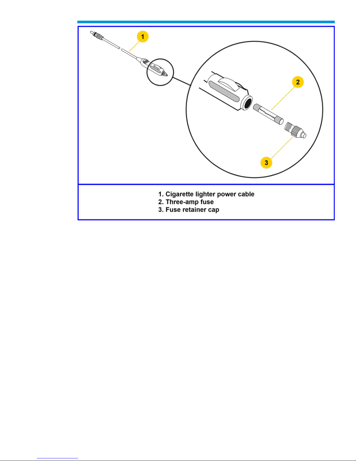
Cigarette Lighter Power Cable 3-Amp Fuse Replacement
A three-amp removable fuse is located in the cigarette lighter power cable (P/N 3000096)
connector. When required, check or replace the fuse by performing the following steps:
1. Ensure cigarette lighter power cable is not connected to vehicle or Tech2.
2. Unscrew fuse retainer cap and remove three-amp fuse.
3. Inspect fuse for damage and replace with identical three-amp fuse if required.
4. Verify by connecting cigarette lighter power cable to Tech2 and vehicle.
71
Page 72
General Motors Tech2 User Guide
Cigarette lighter power cable three-amp fuse replacement
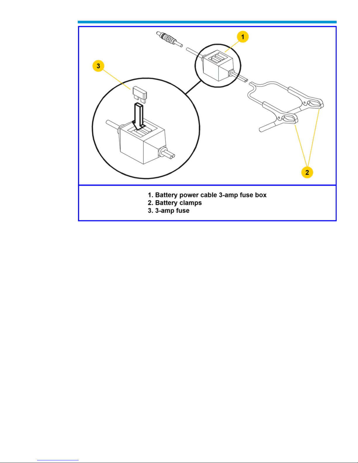
Battery Power Cable 3-Amp Fuse Replacement
Two three-amp fuses are located in the battery power cable (P/N 3000097) three-amp fuse
box. When required, check or replace the fuse(s) by performing the following steps:
1. Ensure battery power cable is not connected to vehicle battery or Tech2.
2. Use a standard fuse puller to remove the fuse(s) from the fuse box.
3. Inspect fuse(s) for damage and replace with identical 3-amp fuse(s) if required.
4. Verify by connecting battery power cable to Tech2 and vehicle battery.
72
Page 73
General Motors Tech2 User Guide
Battery power cable three-amp fuse replacement
CAUTION: To help avoid personal injury by electric shock, make sure the battery power
cable is not connected to the vehicle’s battery before removing the fuse(s).
73
Page 74
General Motors Tech2 User Guide
CANdi Module Troubleshooting
The following troubleshooting information applies only to the CANdi module. This
application is unavailable for most vehicles at the time of writing.
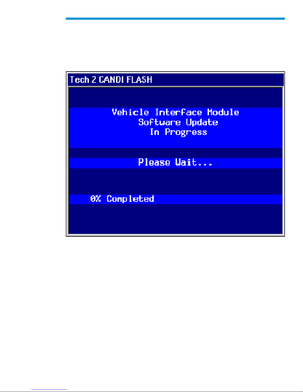
If the Tech2 loses power during programming, the CANdi module will not be properly
programmed. The CANdi module will be automatically reprogrammed when power is
available.
CANdi module programming screen
If a fault occurs during reprogramming, a fault screen may appear. If this occurs, power off
the Tech2 and attempt to reprogram the CANdi module again. If the problem persists,
incorrect CANdi software may be present on the Tech2 PCMCIA card. Connect the Tech2
to the TIS2Web computer and download a new version of the software.
74
Page 75
General Motors Tech2 User Guide
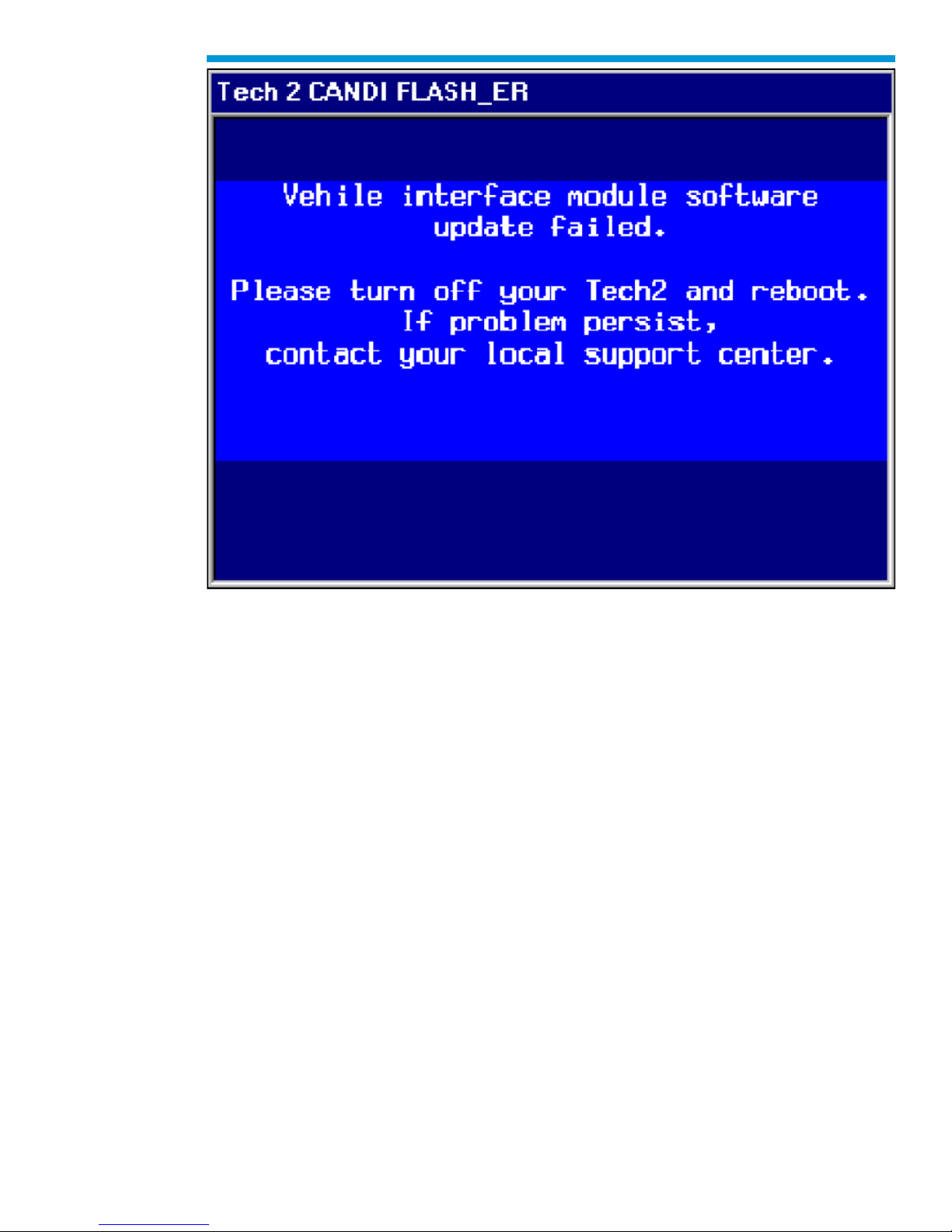
CANdi Fault Screen
NOTE: Do not perform a VCI self-test while the CANdi module is connected. If the CANdi
module is connected and an error screen occurs, disconnect the CANdi module from the
Tech2 and perform the test again.
The screen shown below is displayed when the Tech2 does not detect the CANdi module.
This can occur under the following conditions:
• The CANdi module is not connected to the Tech2, or
• A problem occurred during start-up that prevented the Tech2 from configuring the
CANdi module.
If this occurs, power the Tech2 off and start again. If the problem persists, follow the
troubleshooting tests.
It is also possible to connect a CANdi module after the Tech2 has been powered up via the
VCI. If this occurs, the Tech2 will not detect CANdi module and will not properly
communicate, even if the LED is flashing on the CANdi module. Power off the Tech2 and
start again.
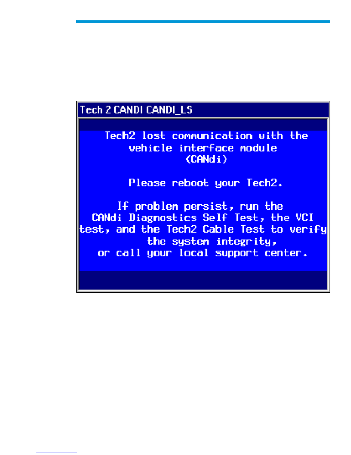
The screen displayed in occurs when the Tech2 loses communication with the CANdi
module. This could be a result of the following:
• VCI not properly seated in the Tech2 slot
75
Page 76
General Motors Tech2 User Guide
• DLC cable not properly connected
• Poor Burndy cable connection to the CANdi module
• Worn or damaged cable that results in a poor connection between the CANdi
module and the VCI If this occurs, check all Tech2 and CANdi module connections,
power off the Tech2 and start again.
If problem persists perform the troubleshooting tests at the F4 Option - on the self-test
menu.
Tech2 lost communication with the CANdi module screen
76
Page 77

General Motors Tech2 User Guide
CANdi Module Diagnostics
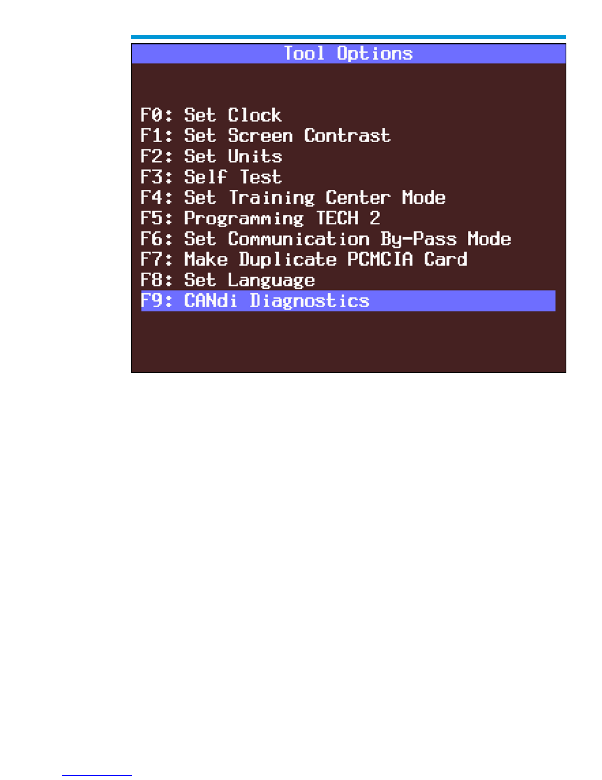
Select “CANdi Diagnostics” from the Tech2’s Tools Options menu. If the CANdi module is
not connected a screen will appear.
CANdi module not detected screen
77
Page 78
General Motors Tech2 User Guide
CANdi Diagnostics selected on Tool Options menu
78
Page 79
General Motors Tech2 User Guide
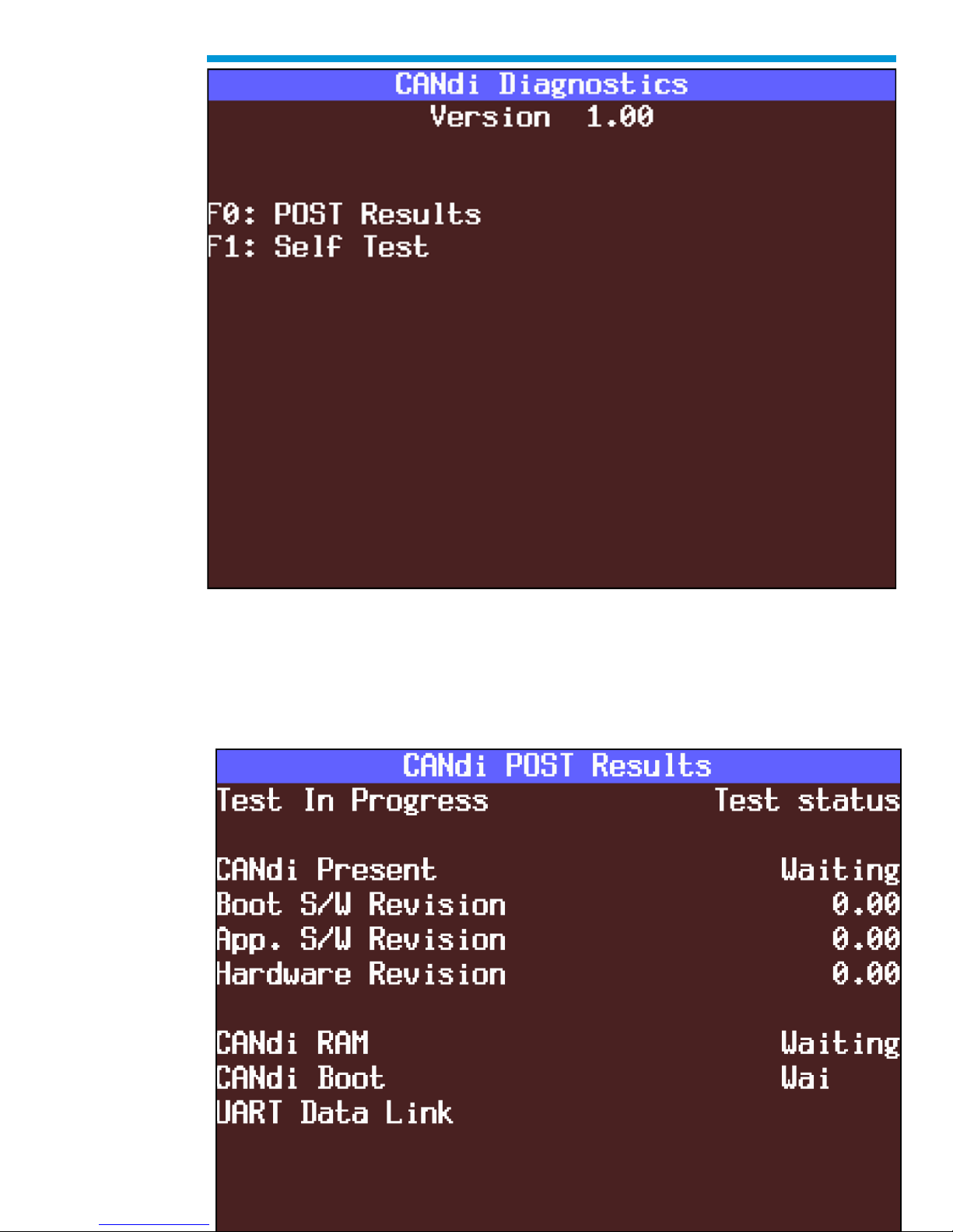
CANdi Diagnostics menu: “POST Results” or “Self Test”
When you select “POST Results” from the CANdi Diagnostics menu, a results screen
appears. You can use the information to determine if the CANdi module had any problems
during its start-up sequence. Software and hardware revision numbers are identified and
displayed.
CANdi POST Results screen
79
Page 80
General Motors Tech2 User Guide
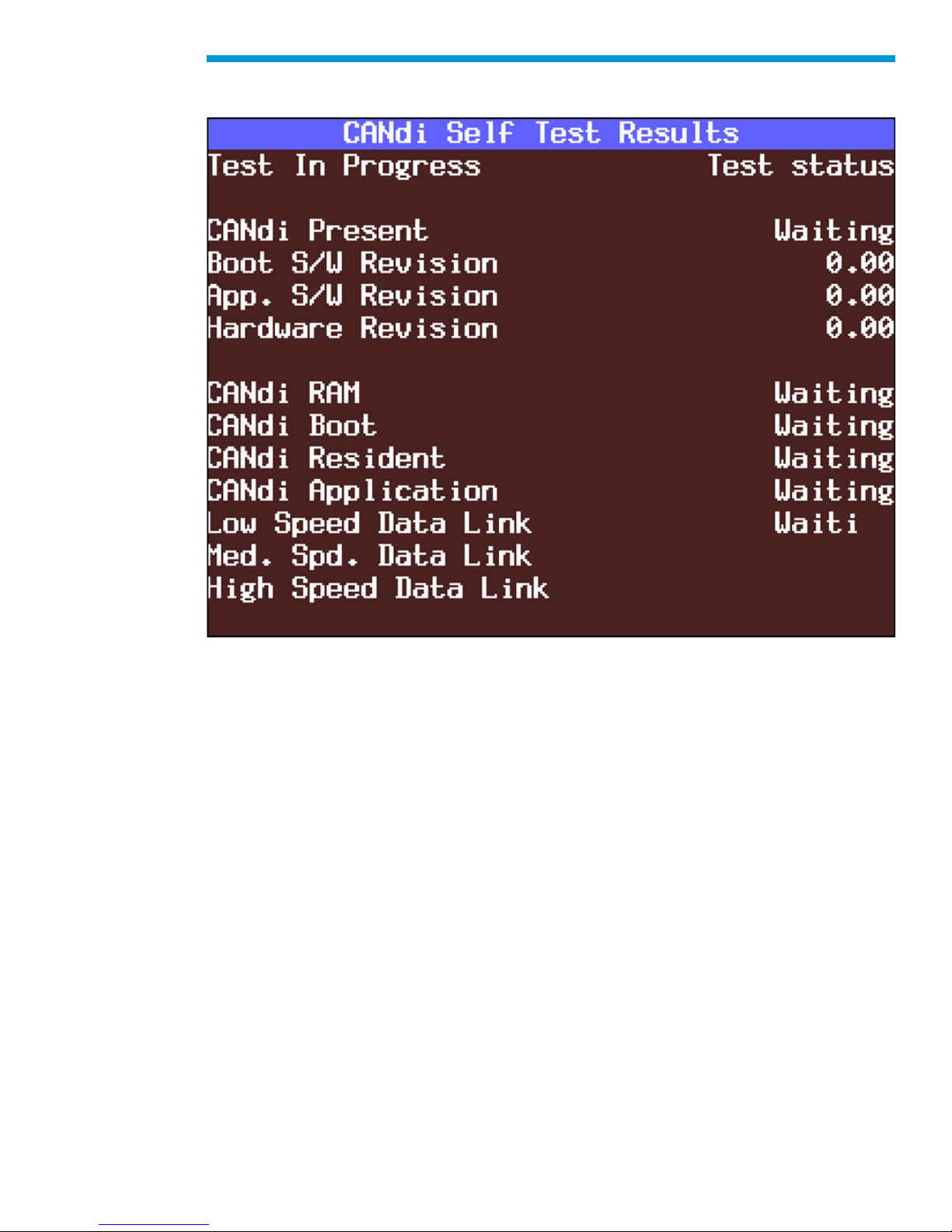
Selecting “Self Test” from the CANdi Diagnostics menu initiates a complete test of the
CANdi module. When testing is complete, all results are displayed.
CANdi Self Test Results screen
CANdi Module Troubleshooting Guide
If a CANdi module is not functioning properly, please perform the following tests:
1. Make sure the CANdi module is properly grounded by connecting to a vehicle or by
using the 12-pin ALDL connector, which has the signal and chassis ground shorted.
IMPORTANT: If not properly grounded, the CANdi module will appear to be defective
when it is not. The CANdi module will fail due to improper grounding if you use the 16-pin
DLC (J-1962) connector and power the Tech2 from an AC/DC power supply. The adapter
you use must have a GM part number. Although PVI adapters are similar to GM adapters,
they will not work with the CANdi module.
2. Verify that the Tech2 passes all stand-alone self-tests. Replace the Tech2 if it fails. If
the Tech2 passes, proceed to step three. The CANdi module must be disconnected to
run self-tests. If the CANdi module is connected, a message will appear instructing you
to disconnect the module.
3. Verify that the VCI passes self-tests. Replace the VCI if it fails. If the VCI passes,
proceed to step four. The CANdi module must be disconnected to run self-tests. If the
CANdi module is connected, a message will appear instructing you to disconnect the
module.
80
Page 81

General Motors Tech2 User Guide
When performing this test, you must also perform the Selectable VCI test (option F4 on the
self-test menu). First install the Burndy loopback adapter into the VCI 26-pin connector,
which does not require the cable. Once you select “Selectable VCI,” select the “More
Tests” soft key. In the new submenu, select “F6: VCI TPU”. If the VCI passes the test, all
the TPU channels will display a Pass indicator as shown in the example at the top of the
next page.
Testing Status
TPU0 Pass
TPU1 Pass
TPU5 Pass
TPU12 and 15 Pass
TPU13 and 14 Pass
The two TPU inputs that the CANdi module requires are TPU12 and TPU15, which enable
the module and detect its presence. If TPU12 and 15 do not appear on the screen, then
they are defective in the VCI module and the VCI is failing to properly enable the CANdi
module. If the above test passes, you must repeat the same test with the Burndy loopback
adapter at the end of the cable. The setup is the same as if you were plugging into a
vehicle without the CANdi module connected and with the loopback adapter at the end of
the cable. Then you must run the VCI TPU test. If the example above appears (TPU13 and
14 are missing in this test because these I/Os don’t go through the cable), then the cable is
also fine. However, if TPU12 and 15 are missing, then the cable is defective.
4. Verify that the DLC cable (also known as the ALDL, J-1962, or OBDII interface cable) is
functioning properly and then proceed to step five. Replace the DLC cable if it does not
function properly. Call the ACDelco Aftermarket Support Center at 1-888-212-8959 for
more information if you have trouble with this test.
5. Connect the CANdi module to the Tech2. Connect the system (Tech2 and CANdi
module) to a vehicle and power on the Tech2. Verify that the LED on the CANdi
module is flashing.
• If the LED does not flash or light up at all, it may be defective and you should
proceed to step six.
• If the LED is not flashing but illuminated, a bad ground may exist somewhere. The
grounding problem could be due to a defective ALDL (J-1962) female interface on
the vehicle. Power the Tech2 through an AC/DC power supply and connect the 12pin ALDL connector. If this fixes the problem with the CANdi (the LED is flashing),
then the vehicle has a grounding problem and the CANdi module is OK.
• If the LED is flashing while connected to the vehicle, but the CANdi module still has
a problem, proceed to step six.
6. If problems persist with the CANdi module, and the Tech2 recognizes the interface,
perform self-test diagnostics on the CANdi module. Select CANdi Diagnostics from the
Tool Options menu to see the CANdi Diagnostics menu. This menu allows you to
display POST results, or request the CANdi module to perform a self-test. Refer to the
main PCB self test for more information.
If a diagnostic test fails, contact the ACDelco Aftermarket Support Center at 1-888-2128959 before returning the CANdi module. If a known problem with a software version is
identified, ACDelco Support will inform you to update Tech2 software with the correct
81
Page 82

General Motors Tech2 User Guide
software version number. If there is no known problem with the Tech2 software, you will
be directed to contact the hardware manufacturer.
CANdi Module Repair
If CANdi fails and the ACDelco Aftermarket Support Center (888-212-8959) has verified
that it needs repair, you may contact a Bosch Diagnostics/Vetronix repair center to discuss
the options available to you.
Bosch Diagnostics/Vetronix Warranty Repair Centers:
1-855-267-2483 prompt #1
United States and Latin America
Bosch Diagnostics/Vetronix
153 Castilian Drive
Goleta, CA 93117
U.S.A.
Canada
Custone Electromotive Inc.
1150 Champlain Court
Whitby, ON L2N 6A8 Canada
Part numbers - CANdi module: J-45289 (SPX), 3000164 (GM), 02003039 (Bosch
Diagnostics/Vetronix) Connectors: 12-pin #3000099 and loop back #3000109
Additional CANdi Troubleshooting Tips
Transformer voltage output test using DVOM:
• Set DVOM to Volt setting.
• Probe cable end inside and outside the computer.
• Twelve volts is the minimum.
82
Page 83

General Motors Tech2 User Guide
Updating the CANdi module:
IMPORTANT: You must use a 32-megabyte (32-MB) PCMCIA card in the Tech2, not a 10megabyte (10-MB) card.
You must update the 32-MB PCMCIA card before connecting the CANdi module to the
Tech2. Always disconnect the CANdi module from the Tech2 before downloading software
updates to the PCMCIA card.
The CANdi module is capable of storing up to three different software versions.
Will the CANdi module require updates?
Possibly. The CANdi module ships complete with software, but possibly not the most
current version.
• Be sure to update the Tech2 with the latest software before using the CANdi
module. The CANdi module will compare software and look for a possible update
from the Tech2. When you update the Tech2, any software updates for the CANdi
module will download to the PCMCIA card. The CANdi module will automatically
receive updates each time it is connected to the DLC and Tech2 at power-up.
Therefore, it is very important that you always run the latest available software
version when using the CANdi module.
83
Page 84
General Motors Tech2 User Guide
Software
Software related to the Tech2 is described in four subsections:
A) Tech2 Main Menu and Live Plot
B) TIS2Web – Web-based Technical Information System (TIS)
C) Service Programming System (SPS)
D) Controller Area Network Diagnostic Interface (CANdi)
IMPORTANT: Proper PCMCIA updates are required and are essential for successful
vehicle diagnoses. Refer to the Programming Tech2 function under Tool Options, and the
Tech2 PCMCIA Card in the TIS2Web subsection
Tech2 Main Menu
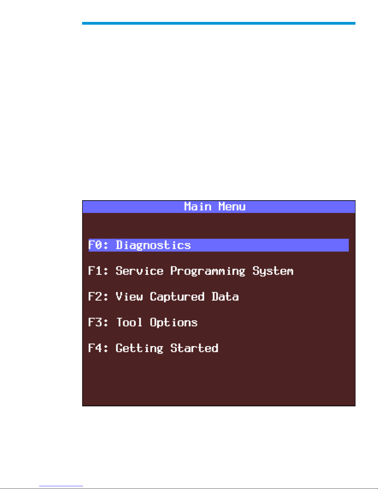
Five primary functions or “paths” are available on the Tech2’s Main Menu:
Diagnostics, Service Programming System, View Captured Data, Tool Options, and
Getting Started are all described in more detail on the following pages.
Tech2 Main Menu
84
Page 85

General Motors Tech2 User Guide
Diagnostics
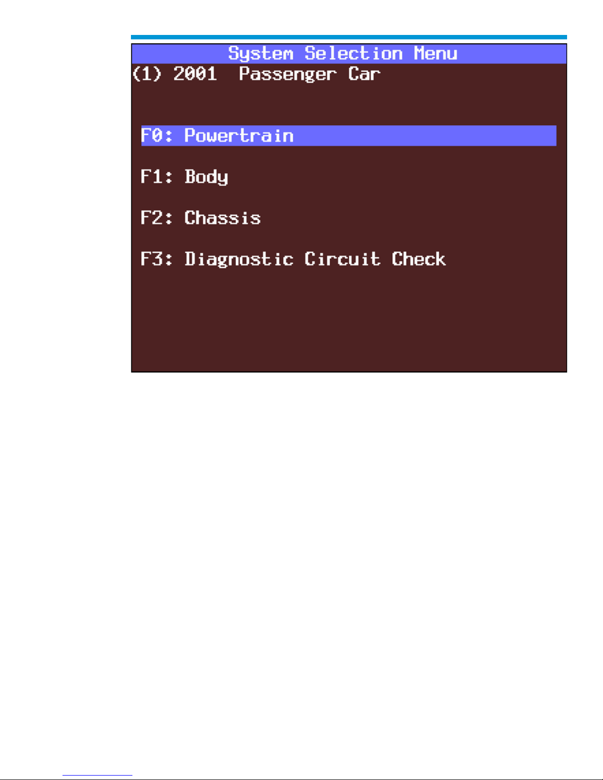
Selecting Diagnostics from the Tech2 Main Menu and identifying the vehicle as shown
below gives you access to four major systems: Powertrain, Body, Chassis, and Diagnostic
Circuit Check.
F0: DIAGNOSTICS
↓
Vehicle Identification:
Select Model Year
↓
Select Vehicle Type
Passenger Car
LD Trk, MPV, Incomplete
Medium Duty Truck, Saturn
↓
Select System
↓ ↓ ↓ ↓
F0: F1: F2: F3:
Powertrain Body Chassis Diagnostic Circuit Check
85
Page 86
General Motors Tech2 User Guide
System Selection Menu
86
Page 87

General Motors Tech2 User Guide
Service Programming System
Selecting Service Programming System from the Tech2 Main Menu leads to selections
shown below.
F1: SERVICE PROGRAMMING
(for remote programming only)
↓
Request Info.
↓
Continue (soft key) with Instructions
↓
Vehicle Identification:
Salesmake(s)
↓
Continue (soft key) with Instructions
Model Year(s)
↓
Vehicle Type(s)
↓
Model (body, style)
↓
↓
VIN Verification (Y/N)
↓
Procedural Instructions Screen
87
Page 88

General Motors Tech2 User Guide
View Captured Data
Selecting View Captured Data from the Tech2 Main Menu results in the selections shown
below.
F2: VIEW CAPTURED DATA
↓ ↓
Capture Info Snapshot
↓ Select Items, Plot, Select Frame, AutoReverse, Stop, Auto Forward
F0: DTC Information First Frame, Trigger Frame, Last Frame, Units, Previous Frame,
F1: Freeze Frame / Failure Records Next Frame DTC, Previous DTC-Chg, Next DTC-Chg
Live Plot - Change Min/Max, Zoom In-Out
Tool Options
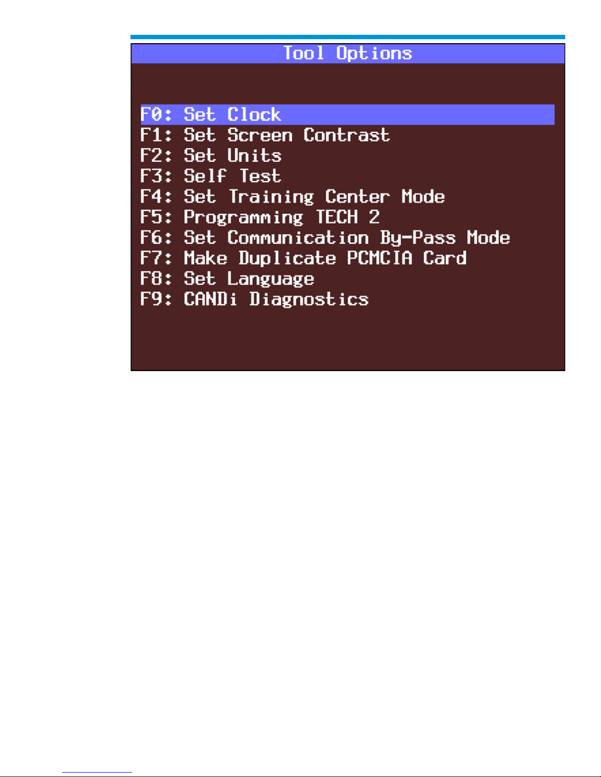
Selecting Tool Options from the Tech2 Main Menu gives you the Tool Options menu,
leading to 10 major selections, as follows:
F3: TOOL OPTIONS
↓
F0: Set Clock
F1: Set Screen Contrast
F2: Set Units
( Metric or English )
F3: Self Test
F4: Set Training Center Mode
( Instructor or Student )
F5: Programming Tech2
F6: Set Communication By-Pass Mode
F7: Make Duplicate PCMCIA Card
These features—described in more detail on the following pages—are useful for controlling
various Tech2 settings including the self tests and CANdi diagnostics.
F8: Set Language
F9: CANdi Diagnostics
88
Page 89
General Motors Tech2 User Guide
Tool Options menu
F0: Set Clock
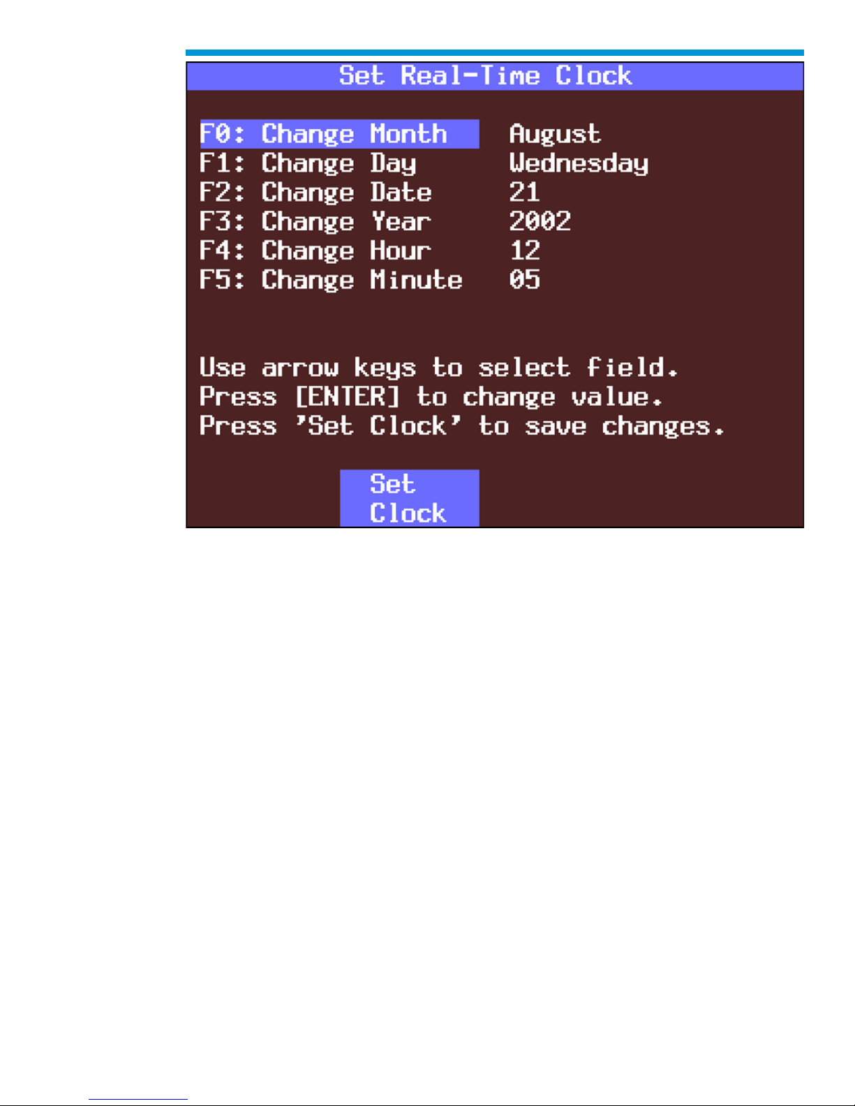
After you select F0: Set Clock from the Tool Options menu and the Set Real-Time Clock
menu appears, you can set the internal Tech2 real-time clock in two ways:
1. Use the up and down arrow keys to move the cursor to desired selection. Press
[ENTER] to change the value. Each time [ENTER] is pressed the value will be
increased by one unit until a preset maximum unit is reached. Once all correct
values are entered, press the Set Clock soft key to save all changes.
2. Use the function key of the desired selection to change an incorrect value. Each
time the function key is pressed the value will be increased by one unit until a
preset maximum is reached. Once all correct values are entered, press the Set
Clock soft key to save all changes.
89
Page 90
General Motors Tech2 User Guide
Set Real-Time Clock menu
F1: Set Screen Contrast
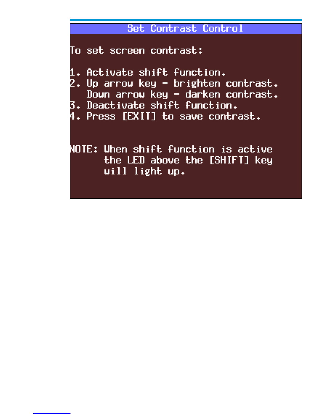
Selecting F1: Set Screen Contrast reveals a Set Contrast Control screen that instructs you
on how to set and save the screen contrast to optimize the tool’s visibility in your lighting
conditions.
Important: The Set Contrast Control tool option adjusts the permanent default contrast
setting of Tech2 display
Because of the nature of the LCD (Liquid Crystal Display), you will experience some
contrast variance.
When the temperature of the Tech2 increases the display will brighten slightly. As the
temperature of the Tech2 decreases, the display will darken. This variance is a
characteristic of an LCD screen and should be considered normal operation.
The screen contrast control setting described above may not account for the entire
variance of operating temperatures. Set a default setting which is mid-range between the
operating temperatures. Screen contrast may be adjusted during any function by pressing
the SHIFT key and using the up and down arrows for adjustment. Periodic adjustments
may be necessary, but settings outside of this application are only retained during the
current power-up session.
90
Page 91
General Motors Tech2 User Guide
Set Contrast Control screen
F2: Set Units
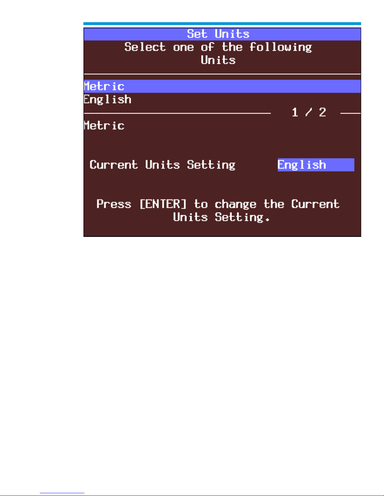
When you select the F2: Set Units option, a Set Units screen will appear. Use the up and
down arrow keys to change the Current Units Setting from English to Metric or vice versa,
if desired. Press [ENTER] to save your setting as the default.
91
Page 92
General Motors Tech2 User Guide
Set Units screen
F3: Self Test
Selecting F3: Self Test gives you access to the Tech2 Self Test menu screen, which will
help you to verify that the Tech2 is functioning normally. Refer to Section VI Troubleshooting for more information on this area.
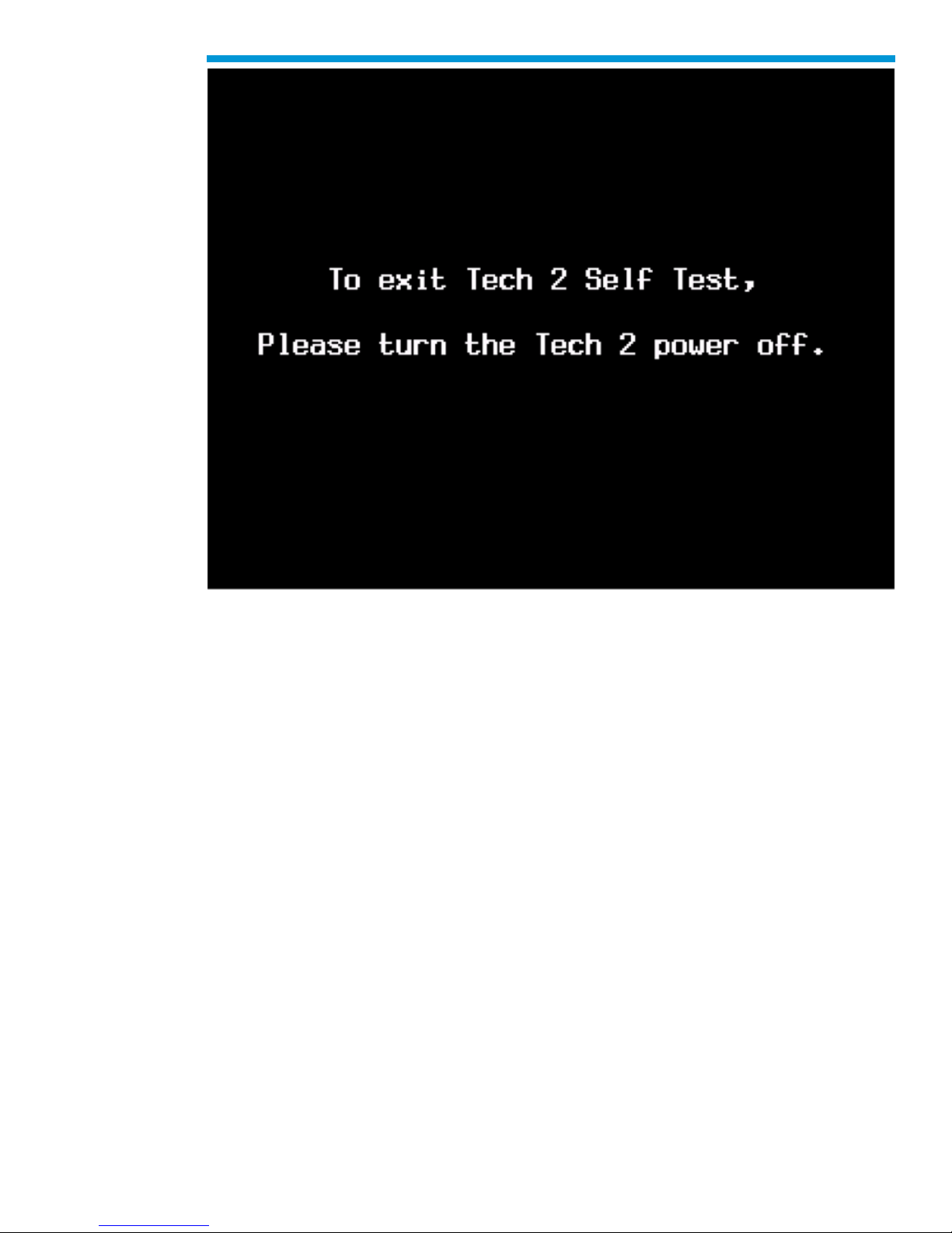
Power Down Screen. After completion of any Self Test, return to the Tech2 Self Test menu
screen. After pressing [EXIT], a screen will appear instructing you to turn the Tech2 power
off. Turn off the Tech2 and turn back on to continue.
92
Page 93
General Motors Tech2 User Guide
Tech2 power down screen
F4: Note: This function is for Training Centers with an instructor only.
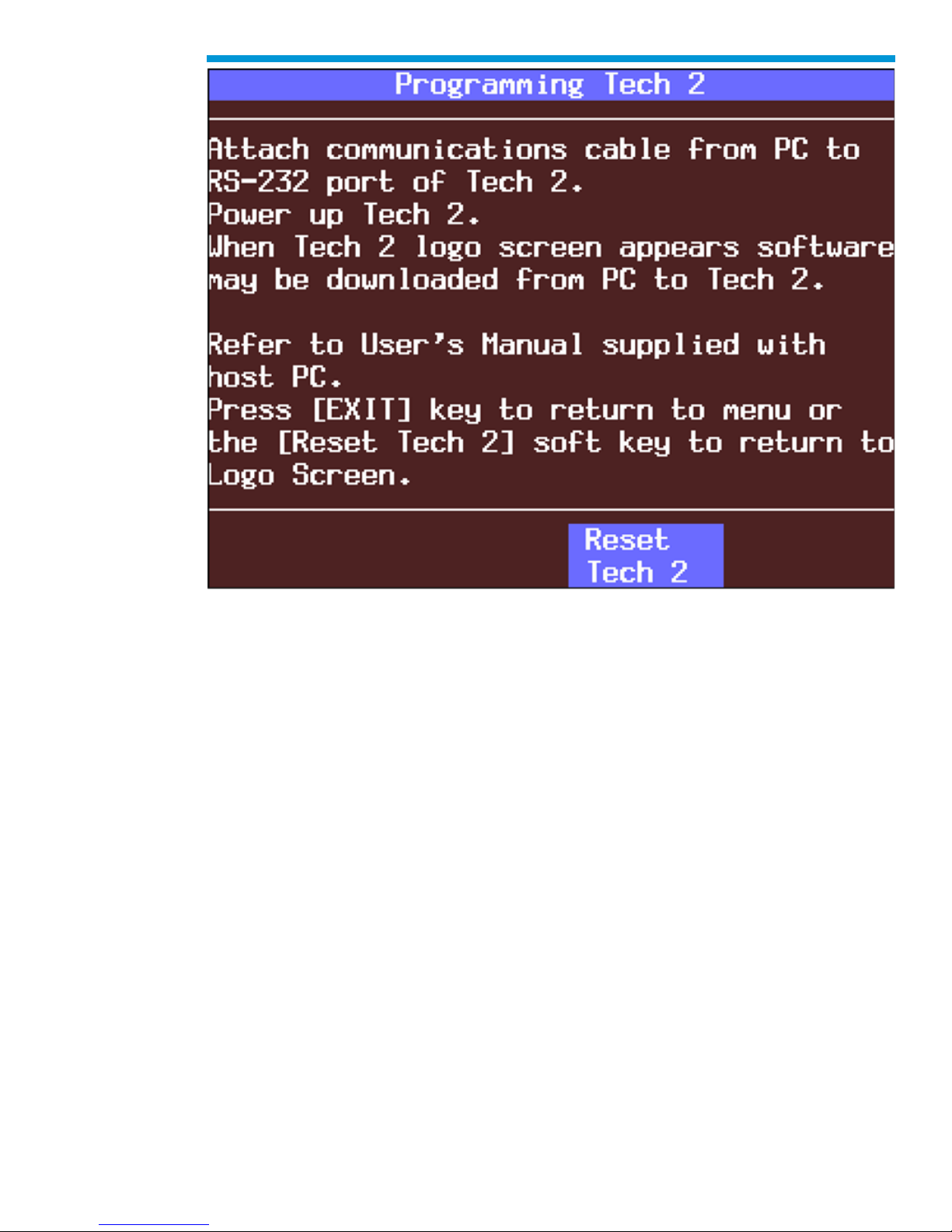
F5: Programming Tech2
After you select F4: Programming Tech2, you can follow the on-screen instructions for
downloading from a PC to the Tech2 scan tool via the RS-232 cable. Refer also to
Software Download, Tech2 PCMCIA Card, and Tech2 Update Procedure later in this
section.
93
Page 94
General Motors Tech2 User Guide
Programming Tech2 screen
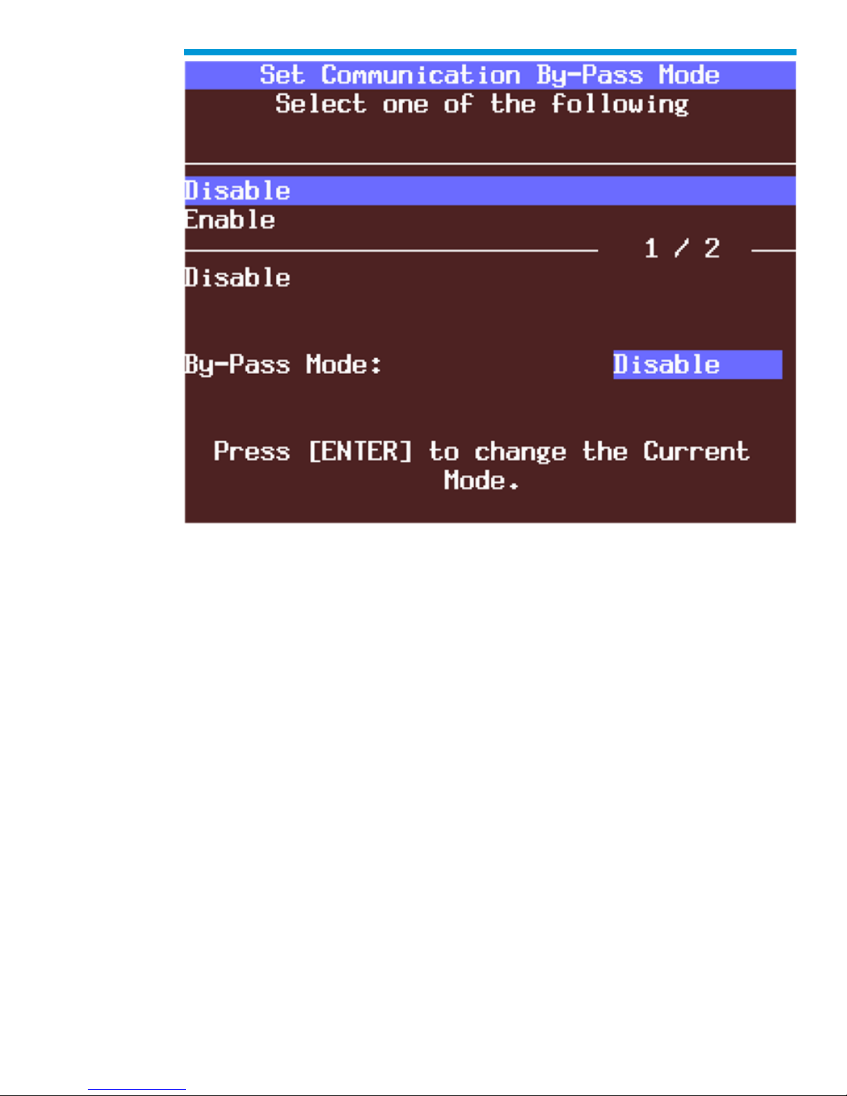
F6: Set Communication By-Pass Mode
When you select F5: Set Communication By-Pass Mode, the upcoming screen offers
Disable and Enable options. By enabling the by-pass mode, the Tech2 bypasses error
handling and allows the user to view data display information without being connected to a
vehicle. Highlight the desired setting using the up or down arrow keys, then press [ENTER]
to change the current mode. The Tech2 will default to the Disable mode after it has been
powered off.
94
Page 95
General Motors Tech2 User Guide
Set Communication By-Pass Mode screen
F7: Set Language
The F6: Set Language option enables you to set your language preference.
F8: CANdi Diagnostics
When you select F7: CANdi Diagnostics (a function limited to certain vehicles), the CANdi
Diagnostics screen appears and you may perform a complete diagnosis of the CANdi
module.
Refer back to CANdi diagnostics section for more information.
95
Page 96
General Motors Tech2 User Guide
Getting Started
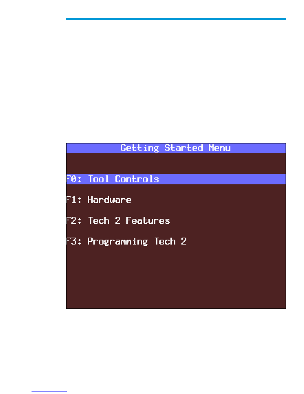
Selecting Getting Started - from the Tech2 Main Menu there is an on-line overview of the
Tech2 and useful operation information.
The following options are available from the Getting Started Menu.
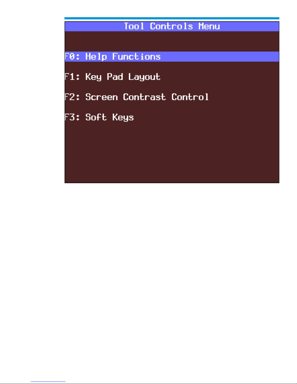
F0: Tool Controls - Selecting an option from the Tool Controls Menu will give you
information on Tech2 help functions, key pad layout, screen contrast control, and soft keys.
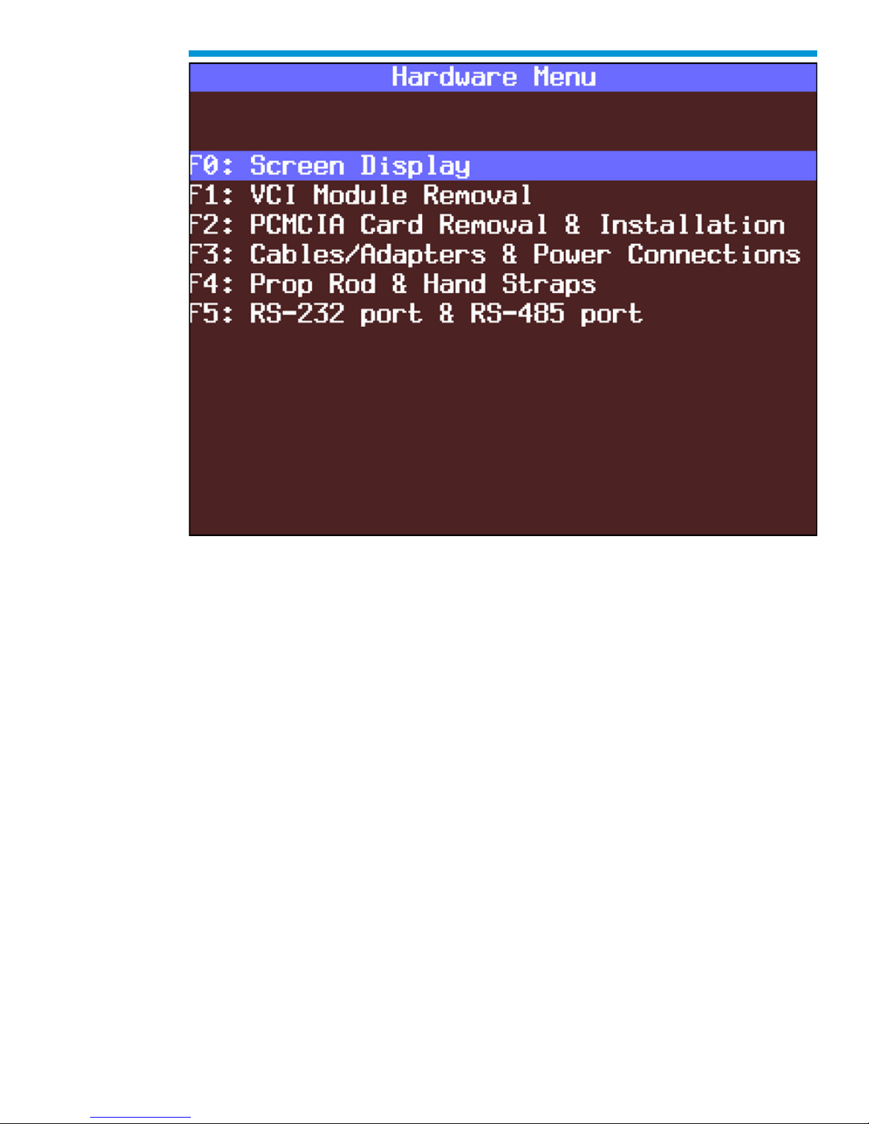
F1: Hardware - The Hardware Menu offers information on screen display, VCI module
removal, PCMCIA card removal and installation, cables/adapters and power connections,
prop rod and hand straps, and RS-232 and RS-485 ports.
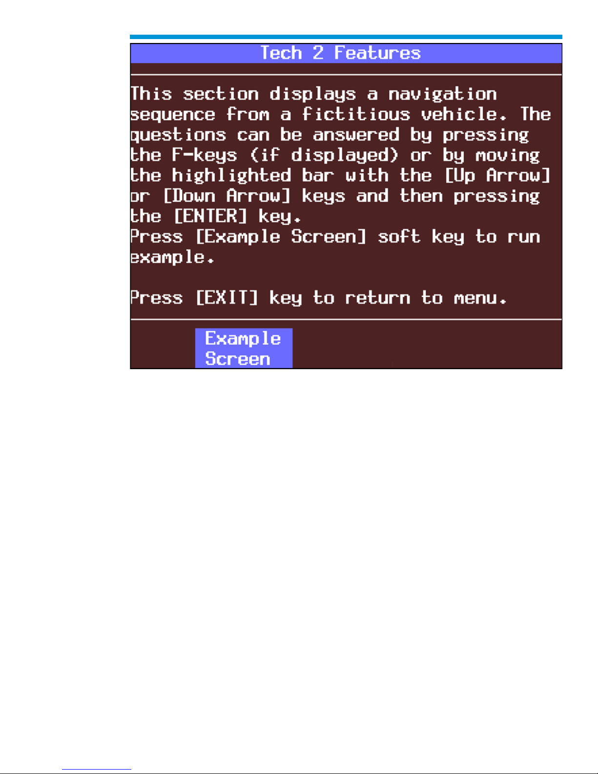
F2: Tech2 Features - This selection displays a vehicle information entry sequence for a
fictitious vehicle.
F3: Programming Tech2 - This option provides instructions for downloading from a PC to
the Tech2 scan tool. Due to a specific sequence of events in the evolution of the Tech2,
this option duplicates the Programming Tech2 function of the Tool Options Menu.
Getting Started Menu
96
Page 97
General Motors Tech2 User Guide
Tool Controls Menu
97
Page 98
General Motors Tech2 User Guide
Hardware Menu
98
Page 99
General Motors Tech2 User Guide
Tech2 Features screen
1. Select F0: Diagnostics from the Tech2 Main Menu, “build” the vehicle, and select a
system—powertrain, body, or chassis.
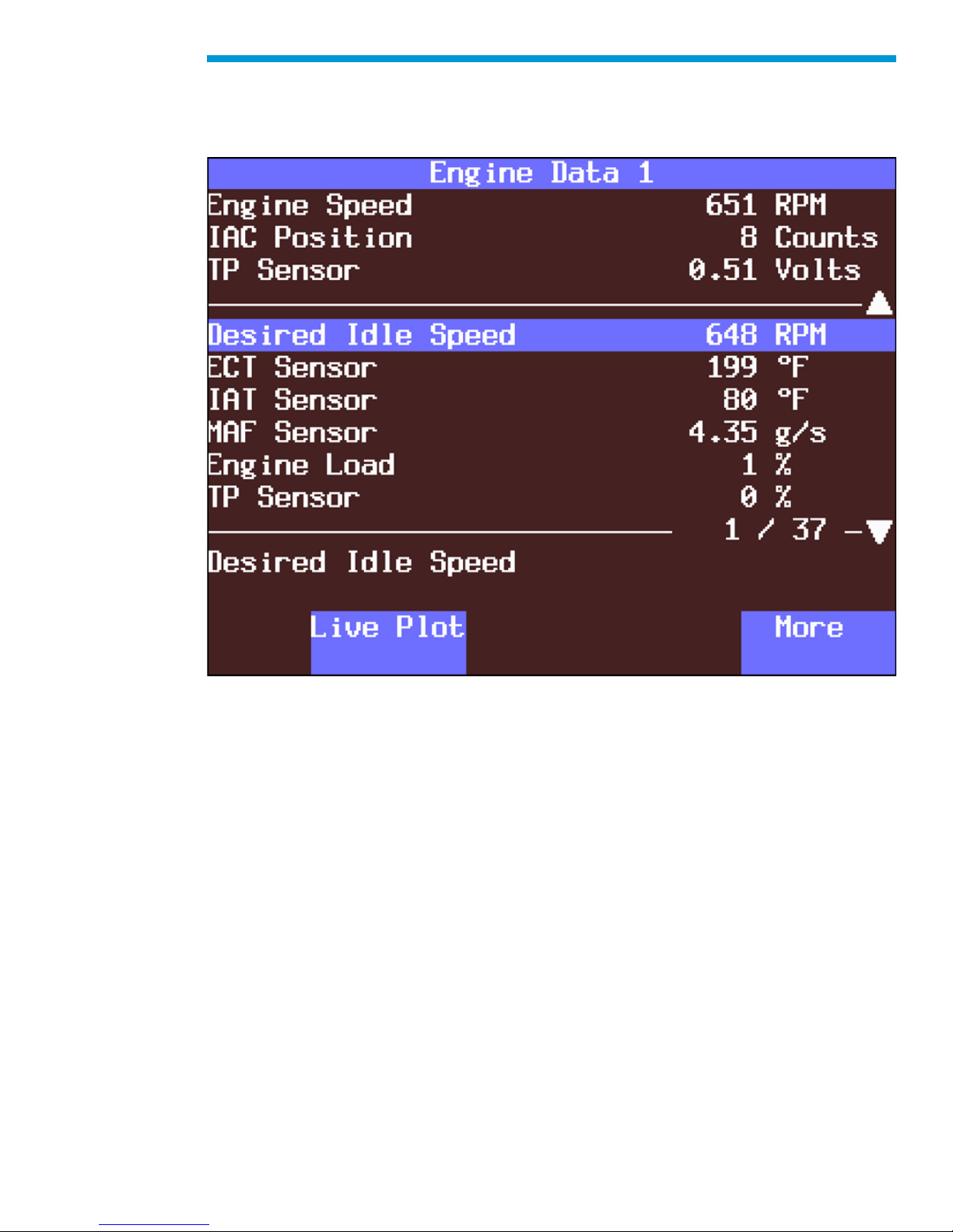
2. From Data Display, select the ‘More’ soft key twice to bring up the Live Plot soft key.
3. Once up to three parameters are selected, select Accept to see a graph of the data.
Live Plot
Live Plot is a Tech2 feature that allows data display parameters to be graphed in real time
as it happens. The Live Plot function will allow up to three parameters to be plotted on a
graph at one time. The data of these parameters will be plotted as the information is
received on the Tech2 from the vehicle. This may aid in the diagnosis of an intermittent
vehicle condition by enabling the user to view data from the vehicle graphically. Any spikes
or drops on the graph can be analyzed immediately. Previously, data had to be captured
before it could be plotted. The Live Plot application is available from the Data Display,
Quick Snapshot, and Snapshot applications on the Tech2.
Screen Display Samples:
1. Select F0: Diagnostics from the Tech2 Main Menu, “build” the vehicle, and select a
system—powertrain, body, or chassis.
2. From Data Display, select the ‘More’ soft key twice to bring up the Live Plot soft key.
3. Once up to three parameters are selected, select Accept to see a graph of the data.
99
Page 100
General Motors Tech2 User Guide
4. All of the features on the resulting graph are available while Live Plot is functioning.
Pressing the More soft key leads to options that allow the user to zoom in and out on
the plotted graph 50 frames at a time and change the min/max values of a highlighted
data parameter.
“Live Plot” soft key on data screen
100
 Loading...