

Page 1

Model no.: M02
Use r ’s Man u a l
M02-00150101
48011201231000
110609010008
Page 2

©2015, Shenzhen General Measure Technology Stock Co., Ltd reserves all copyright.
Without permission from Shenzhen General Measure Technology Stock Co., Ltd.,
Any corporations or person must not copy, spread, record or translate into other
language by any forms.
Our company reserved the right to update user ’s manual without additional
notice to customers by reason of update, so please visit our website or contact
with our service person to get update information.
Website: http://www.szgmt.com.cn
Page 3

CONTENTS
1 General Description....................................................................................... 1
1.1 Functions and Characteristics ....................................................... 1
1.2 Front Panel......................................................................................... 2
1.3 Technical Specifications
...................................................................
3
1.3.1 Common
.................................................................................
3
1.3.2 Analog.....................................................................................4
1.3.3 Digital...................................................................................... 4
2 Installation and Wiring................................................................................... 5
2.1 Connection of Power Supply........................................................... 5
2.2 Connection of Load Cell
...................................................................
5
2.2.1 6-wired Connection
..............................................................
6
2.3 I/O terminals....................................................................................... 7
2.4 Optional Expansion Board Output.................................................. 8
2.4.1 Analog Output (Optional))................................................. 8
2.4.2 Serial Interface RS485 Output..........................................11
2.4.3 Serial Interface RS232 Output
.........................................
12
Page 4

3 Calibration
.....................................................................................................
13
3.1 Instruction
.........................................................................................
13
3.2 Flow Chart of Calibration
...............................................................
14
3.3 Millivolt Value Display..................................................................... 20
3.4 Calibration with Weights.................................................................20
3.5 Millivolt Calibration.......................................................................... 20
3.6 Calibration Switch for Communication Interface
........................
22
3.7 Explanation for Calibration Parameters
.......................................
23
4 Working Parameters Setting
......................................................................
25
4.1 Flow Chart of Working Parameters Setting.................................25
4.2 Parameter Setting Method.............................................................27
4.3 Descriptions of Operation Parameters........................................ 28
4.4 Set point parameters
......................................................................
31
5 I/O Definition
.................................................................................................
33
5.1 I/O Definition
....................................................................................
33
5.2 I/O testing......................................................................................... 35
6 Serial Communication................................................................................. 36
Page 5

6.1 r-Cont
................................................................................................
37
6.2 r-SP1
.................................................................................................
37
6.2.1 Parameters Code Chart
....................................................
37
6.2.2 Error Code Explanation..................................................... 40
6.2.3 Command............................................................................ 40
6.3 tt TOLEDO........................................................................................48
6.7.1 Modbus Communication Address
....................................
53
7 Password Input and Setting, Reset
..........................................................
60
7.1 Password Input
................................................................................
60
7.2 Password Setting............................................................................ 60
7.3 Factory Reset.................................................................................. 62
8 Display Testing............................................................................................. 64
9 Errors and Alarm Messages
.......................................................................
65
10 Dimension of Indicator
..............................................................................
66
6.4 Cb920................................................................................................49
6.5 rECont............................................................................................... 50
6.6 rEREAD
6.7 Modbus............................................................................................. 52
............................................................................................
51
Page 6

M02 Digital Indicator
1
Small volume, unique design, easy operation
Applicable to all kinds of resistance strain gauge bridge load cell
Front panel numerical calibration
Multilevel of digital filter
Automatic zero -tracking
Automatically zero when powered on
4 set points
1 input and 2 outputs
Serial communication interface:RS232 or RS485
Calibration via serial interface
Optional interfaces: Analog output, serial interface
1 General Description
M02 weighing indicator is specially designed for weight transmitting in industrial
fields.
This indicator has the features of small volume, plenty communicating commands,
stable performance, easy operation and practicability. It can be widely applied to
concrete and bitumen mixing equipment, metallurgy furnace and converter, chemical
industry and feed, etc. .
1.1 Functions and Characteristics
Page 7
M02 Digital Indicator
2
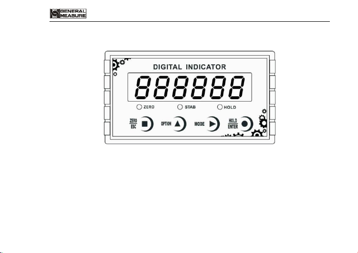
ZERO: Light on when present weight is within 0±1/4d.
STAB: Light on when changes of weight values are within the range of motion
HOLD: Light on when indicator displays the value of D/A output.
1.2 Front Panel
M02 Front panel
Main Display:6 digits, for displaying weight and the information of parameters.
Status Indicator Lamp:
detecting during motion detecting time.
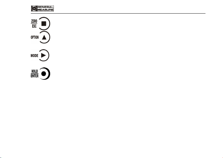
Keypad:
Page 8
3
: Zero/Esc, Used to exit from current operation or go previous.
1.3.1 Common:
: Used to scroll optional values of parameter and to make flashing digit
increase 1 while data inputting.
: Function Selecting Key, To make flashing position move to the right digit
when data inputting.
: Confirming Key. Used to confirm present operation.
1.3 Technical Specifications
Power supply: DC24V±5%
Working temperature: -10~40℃
Max humidity: 90%R.H without dew
Power consumption: About 10W
Dimension: 105×89×57(mm)
M02 Digital Indicator
Page 9

4
1.3.2 Analog:
Load cell power: DC5V 200mA(MAX)
Input impedance: 10MΩ
Zero steady range: 0.00~12mV(Load cell 3mV/V)
Input sensitivity: 0.1uV/d
Input range: 0.00~15mV(Load cell 3mV/V)
Transfer mode: Sigma - Delta
A/D conversion speed: 15, 30, 60, 120, 480, 960 times/sec
Non-linearity: 0.01% F.S
Gain drift: 10PPM/℃
Display Precision: 1/100,000
1.3.3 Digital:
Weight display: 6 digits red high-brightness LED
Minus display: “-”
Overload display: “OFL”
Decimal point: 5 kinds (optional)
Function keys: 4 keys soniferous keypad
M02 Digital Indicator
Page 10
M02 Digital Indicator
5
2 Installation and Wiring
2.1 Connection of Power Supply
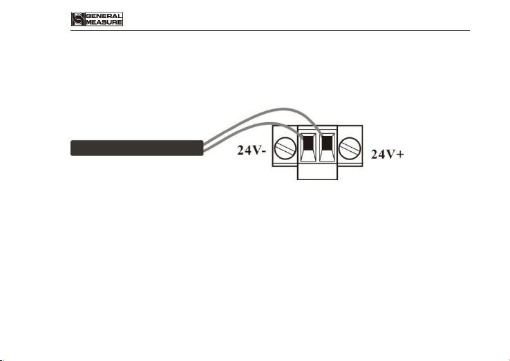
M02 weighing indicator connects DC24V power supply as follows:
Power supply connection
2.2 Connection of Load Cell
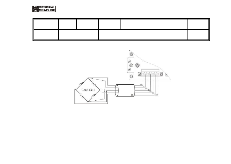
M02 weighing indicator connects bridge type resistance strain gauge load
cells by 6 wires or 4 wires as follows. When you use 4-wired load cells, you must
bridge the SN+ with EX+ and bridge the SN- with EX-.
The signal definition of each port of the load cell connector is as follows:
EX+: Excitation+ EX-: Excitation- SN+: Sense+ SN-: Sense- SIG+: Signal+ SIG-: Signal-
Page 11
6
6 wires
EX+
SN+
EX-
SN-
SIG+
SIG-
Shield
4 wires
EX+
EX-
SIG+
SIG-
Shield
2.2.1 6 wires connection
Note:
1. As load cell output sensitive analog signal, please use shield cable to separate
with other cables, especially AC power.
2. 4 wires connection is suitable for short distance and stable temperature or low
precision field, otherwise use 6 wires connection.
3. For more load cells parallel connection, their sensitivity (mV/V) should be same.
M02 Digital Indicator
Page 12
7
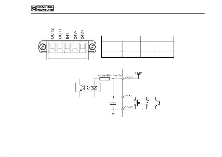
2.3 I/O terminals
I/O tolerant definition as follows:
Output
Input
OUT1
Stable
IN1
Reset
all
OUT2
OFL
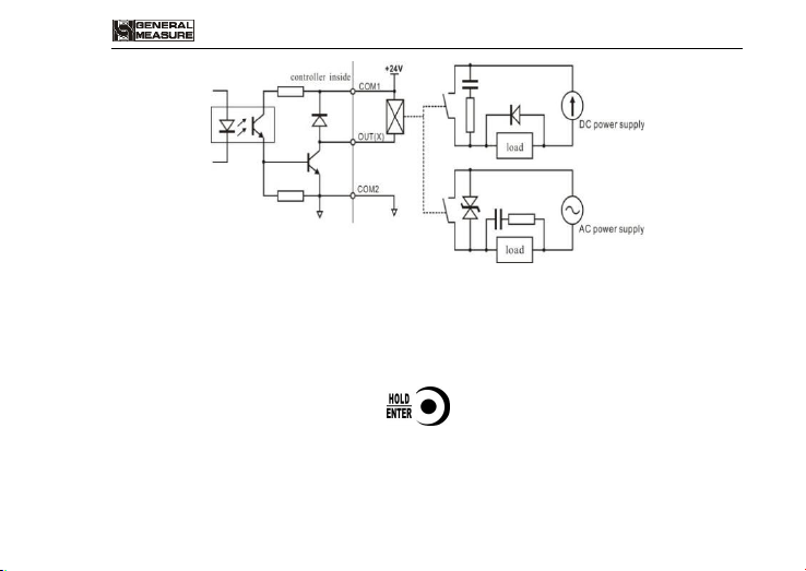
Indicator input terminal connection:
Indicator input terminal connection:
M02 Digital Indicator
Page 13
M02 Digital Indicator
8
2.4 Optional Expansion Board Output
M02 weighing indicator supports analog output, RS232 or RS485 as optional
output function, please confirm it when place orders.
2.4.1 Analog Output (Optional)
At normal displaying status, press to check the analog output.
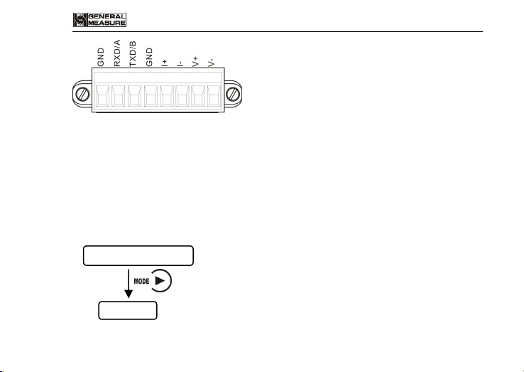
The definition of analog output as below:
Page 14
9
Analog output two types:
The definition of analog output:
V+: voltage-output+, V-: voltage-output-
I+: current-output +, I-: current-output -
Note: only support calibration under current
mode. 4 points must be finished for current
calibration.
SET UP
Normal display status
1) Voltage output: 0-5V/0-10V is optional .
2) Electric current output: 4-20mA/0-20mA/0-24mA is optional.
3) User-define function, users can define analog output type and output range.
The analog output has been calibrated before the delivery of the indicators, so
users do not need to make calibration. If analog output is abnormal, users can
calibrate by themselves as follows:(Suggestion: please calibrate under the
instruction of professionals)
M02 Digital Indicator
Page 15
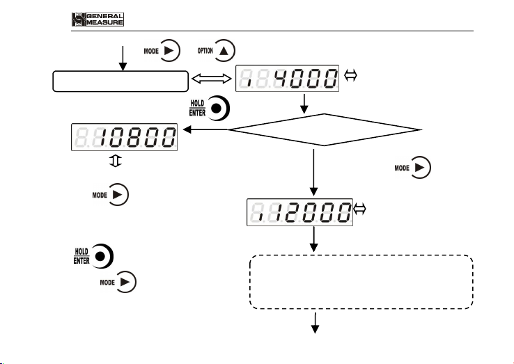
10
Current calibration interface
In this interface,the
multimeter measured
should be 4.000mA.
Measured 4.000mA
If not,press
If yes,press
In this interface,the
multimeter measured
should be 4.000mA.
This interface is current DA
D/A,press to adjust the value,
and the current value measured will
vary accordingly.To adjust it when the
measured value to be 4.000mA, then
press to save and exit.
Then press to calibrate
12.000mA.
Finish the calibration referring to the process of
4.000mA calibration, and the same for the
calibrationof 20mA.
M02 Digital Indicator
and
Page 16
11
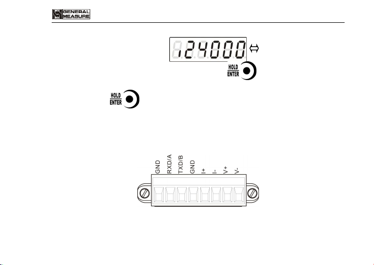
In the interface of highest point calibration,press to enter into analog
This interface is the highest
point calibration of analog
output.
display value interface, the display will be 5 digits (initial value is 24000, means
24.000mA),press to input the value measured by the multimeter.
Note: Analog output calibration, highest point must be calibrated.
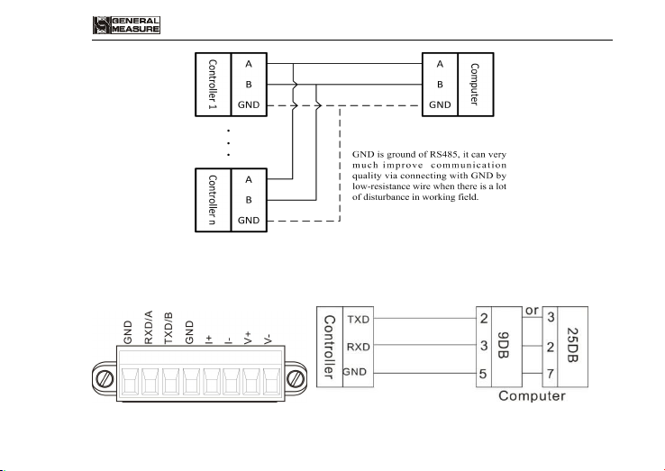
2.4.2 Serial Interface RS485 Output
Serial Interface RS485 output is optional, please refer to chapter 6.0 for
communication protocol.
RS485 serial interface connection:
M02 Digital Indicator
Page 17
12
M02 Digital Indicator
2.4.3 Serial Interface RS232 output (Optional)
RS232 serial interface connection:
Page 18
13
M02 Digital Indicator
3 Calibration
3.1 Instruction
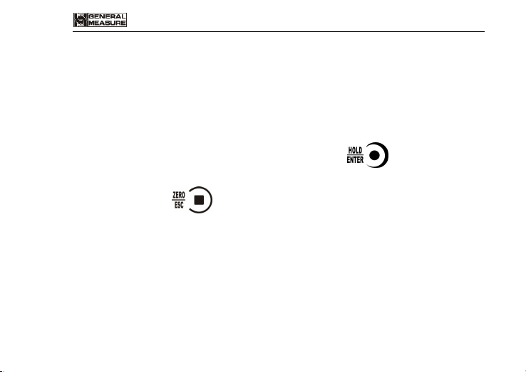
(1)Calibration procedure must be executed when a M02 indicator is put in use at the
first time, the preset parameters may no longer meet the user’s needs, and any part of
the weighing system was changed. Position of decimal point, minimum division,
maximum capacity, zero, and gain can be set and confirmed through calibration.
(2)If you want to set only one parameter, please press to save parameter’s
value and then press to exit.
(3)Please see section 3.7 for parameters’ instruction.
(4)Please record each value in the blank table in section 3.4 during calibration for the
emergency use in future.
(5)See chapter 9 for error alarm message that may be displayed during calibration.
Page 19
14
3.2 Flow Chart of Calibration
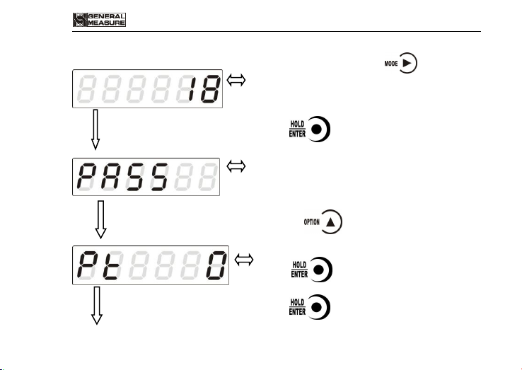
Normal Status
Password input
Decimal point
2. After password is input, the indicator will
display CALON for one second, then go to
next step.
3. Press to select a desired value for
decimal point among 0,
0.0, 0.00, 0.000 and 0.0000, and then
press to save it and enter next step.
If there’s no need to change the value,
press directly to enter next step.
1. Under this status, press (twice),
indicator will display CAL, then
press to enter password input.
M02 Digital Indicator
Page 20
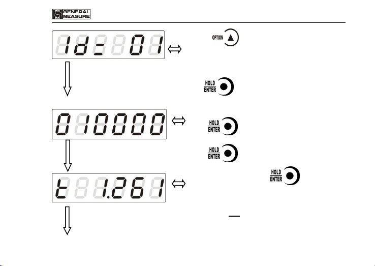
15
Min. divistion
4. Press to select a desired value for min.
division among 1,2,
5,10,20 and 50, and then to save it and enter next
step.
If there’s no need to change the value, then
press directly to enter next step.
Max. capacity
5. Input max. capacity(≤min. division×100000),
press to save it and enter next step.
If there’s no need to change the value, then
press directly to enter next step.
Millivolt value display
6. Under this status, press to enter zero
calibration.
Display value near the output value in millivolt
between SIG+/SIG- of load cell.
See section 3.3 for details about this function.
M02 Digital Indicator
Page 21
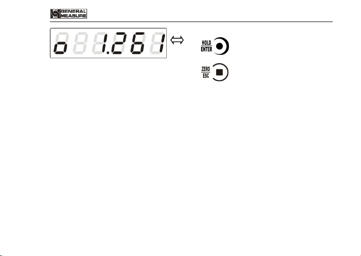
16
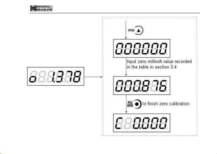
7.Unloaded scale first, when STAB lamp is on,
press to finish zero calibration.
If there’s no need to calibrate zero,
press directly to enter gain calibration.
Zero calibration
M02 Digital Indicator
Page 22
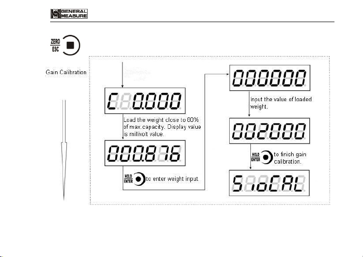
17
M02 Digital Indicator
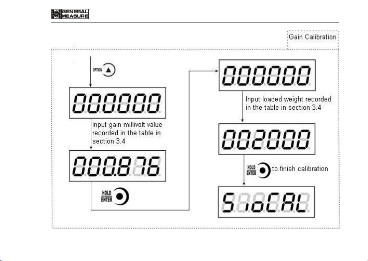
8. The process of gain calibration is as follows. If there’s no need to do gain calibration, press
directly to enter serial ports calibration switch setting.
Page 23
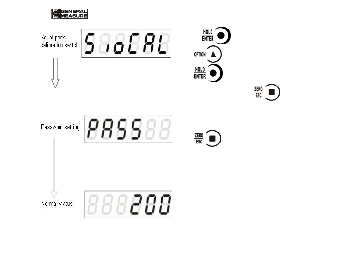
18
9. Press to enter setting interface,
press to choose the switch position,
press to set password。If don’t need to set
switch position, then press to enter password
setting.
10. See section 7.2 for reference to set password.
If there’s no need to set password,
press directly to go back to normal
status.
M02 Digital Indicator
Page 24

M02 Digital Indicator
19
the linearity of load cell is
bad.
*NOTE: You must use
to zero display data before weight is
loaded for each time.
3.3 Millivolt Value Display
This function is mainly used for system test, position-error test for weighing
mechanism and linearity test for load cell.
1. System Test
(1) If display data changes with loaded weight changes, it shows that connection
of load cell is correct and weighing mechanism works well.
(2)If display value is OFL (or –OFL), it means that loaded weight on load cells is
too large (or too small). Please unload the weight (or load more), if display value is still
OFL (or –OFL), the possible reasons are as follows:
a. There is something wrong with weighing mechanism, please check and clear.
b. The connection of load cell is incorrect, please check and clear.
c. Load cells may be damaged, please replace.
2. Position-error Test for Weighing Mechanism
Load a same weight on each corner of weighing mechanism and record
displayed millivolt value respectively. If differences among these values are obvious,
please adjust weighing mechanism.
3. Linearity Test for Load Cell
Load same weight for several times, and record displayed value every time. If
one or two values are obviously much larger or smaller than any others, it means that
Page 25
20
Zero millivolt
value(mV)
Gain millivolt
value(mV)
Loaded
Weight
Date
Remarks
1
2
3
4
5
M02 Digital Indicator
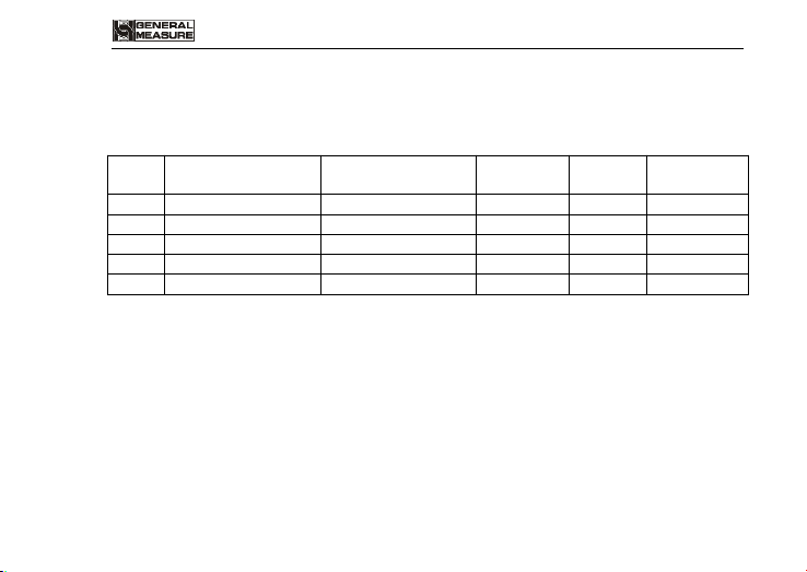
3.4 Calibration with Weights
During calibration with weight ,please record the zero millivolt value, gain millivolt
value and the loaded weight value in the blank table below. If it is not convenient to load
a weight to calibrate, these values can be used for calibration without weights.
3.5 Millivolt Calibration
When it is not convenient to load a weight to calibrate ,alibration can be done without
weights using recorded data in the table in section 3.4.
However, this method is just used for some emergencies, it will make calibration
result incorrect if load cells, or indicator has been replaced.
Page 26
21
M02 Digital Indicator
Page 27
22
M02 Digital Indicator
Page 28
23
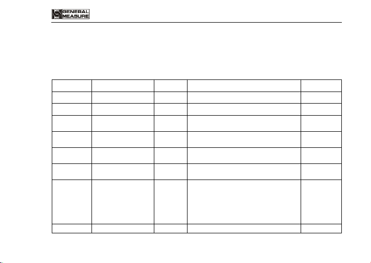
3.6 Calibration Switch for Communication Interface
Symbol
Parameter
Types
Value of parameter
Default
Pt
Decimal Point
5
0 0.0 0.00 0.000 0.0000
0
1d
Min. Division
6
1 2 5 10 20 50
1
CP
Max. Capacity
≤Min. Division×100000
10000
t
Millivolt Value
o
Zero
C
Gain
SIOCAL
Switch for
Calibration
via serial
interface
OFF
PASS
Password Setting
000000
When calibrate the transmitter through serial port( Rs、SP1 or Modbus), must set to
“ON” status for the calibration switch for communication interface.
3.7 Explanation for Calibration Parameters
M02 Digital Indicator
Page 29
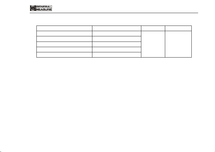
24
Log Table for Calibration Parameters
Parameter
Calibrated Value
Date
Remarks
Decimal Point
Min. Division
Max. Capacity
Load cell sensitivity
Password
M02 Digital Indicator
Page 30
25
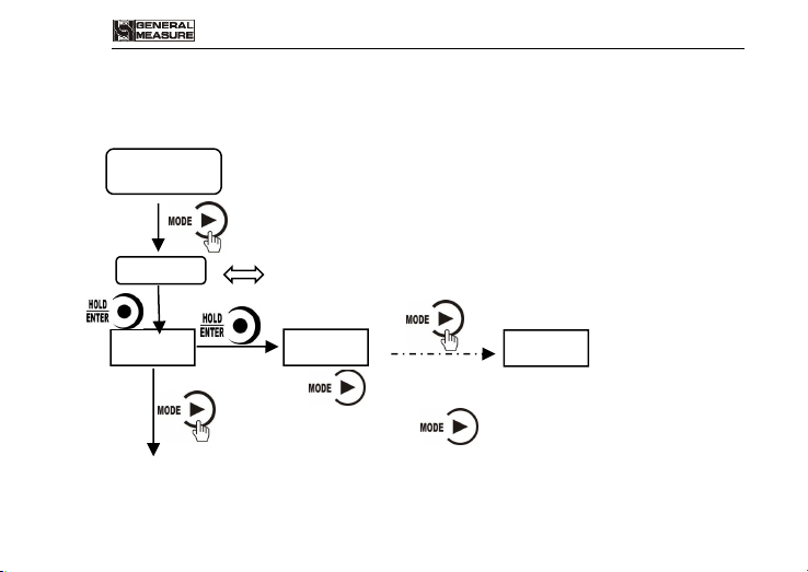
4 Working Parameters Setting
Normal Status
SET UP
F1
F1.1
F1.7
If F4.1(Password Switch) is ON, you
should input password first.
1 .Use to select between the same level. Switch from
display F1 to F2, press .
4.1 Flow Chart of Working Parameters Setting
M02 Digital Indicator
Page 31
26
F2
F3
F2.1
F2.7
F3.1
F3.2
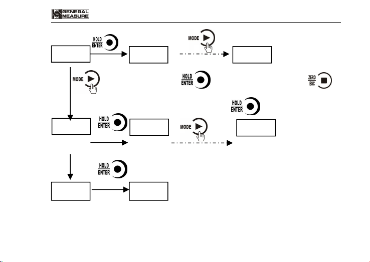
2 .Press to enter into sub-selection, press to
return back to previous menu.
When it displays F2,press to enter into F2.1.
F4
F4.1
M02 Digital Indicator
Page 32
27
Confirm change
OFF
F1.1
ON
F1.1
50
F1.4
50
60
F1.4
M02 Digital Indicator
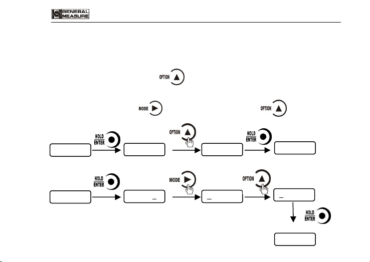
4.2 Parameter Setting Method
M02 has 2 kinds of working parameters: Selection type and data type. For
selection type parameters, press to choose. For data type parameter in
parameter interface, press to choose digit position, pressto choose value.
Selection:
Enter setting status Change OFF to ON Confirm the change
Data:
Enter setting status Move the flashing from 0 to 5 Adjust value
Page 33
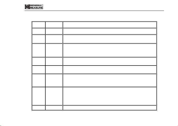
28
4.3 Descriptions of Operation Parameters
Code
Default
Description
F1
Null
The first major term of working parameter.
F1.1
OFF
Switch for Auto-Zeroing when power-on,
OFF: disabled ON: enabled
F1.2
0
Zero-tracking Range(0~9d optional).
This parameter is for automatic calibration, disabled
when is set ”0”.
F1.3
1
Motion Detecting Range(1~9d optional)
F1.4
50
Zeroing Range(00%~99% of Maximum capacity)
F1.55Digital filtering parameter: (1-9 as optional)
0: without filtering
9: strongest digital filtering
F1.6
0
Stable filter parameter (the second filter based on the
first filter): (1-9 as optional)
0: without filtering
9: strongest digital filtering
F1.70A/D conversion rate: 120,480,960,15,30,60 as optional
M02 Digital Indicator
Page 34
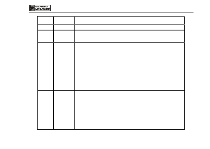
29
F2
Null
The second major term of working parameter.
F2.101Scale no., indicator no.
F2.2
9600
Baud rate of serial port:1200 / 2400 / 4800 / 9600 /
19200 / 38400 / 57600
F2.3
Cb920
Serial ports communication mode:
Modbus-RTU:MODBUS RTU mode;
r-Cont:SP1 continuous mode;
r-SP1: SP1 command mode;
tt:TOLEDOcontinuous mode;
Cb920:Cb920 continuous mode。
rE-Cont:rE continuous mode;
rE- rEAd:rEcommand mode;
F2.4
7-E-1
Data format:
7-E-1:7 data bits,even parity check,1 stop bit;
7-O-1:7data bits,odd parity check,1 stop bit;
8-E-1:8 data bits,even parity check,1 stop bit;
8-O-1:8 data bits,odd parity check,1 stop bit;
8-n-1:8 data bits,no parity check,1 stop bit;
8-n-2:8 data bits,no parity check,2 stop bit;
M02 Digital Indicator
Page 35
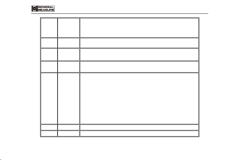
30
F2.5
HiLo
MODBUS dual-byte register storage turn , Hi Lo :
High byte in the front, low byte at the back;Lo Hi:Low
byte in the front, high byte at the back
F2.6
nonE
Cont mode automatic sending time interval
F2.7
0
tt(TOLEDOcontinuous mode)If send the checksum。
0:not send, 1:send.
F3
Null
The third major term of working parameter.
(For analog output only)
F3.1
0-5
Analog output:
4-20:4-20mA
0-20:0-20mA
0-24:0-24mA
0-5: 0-5V
0-10: 0-10V
I_out:Current customized
V_out:Voltage customized
In customized mode,F3.2-F3.5 parameters available
F3.2
3920
Minimum output
F3.3
4000
Zero point output
M02 Digital Indicator
Page 36
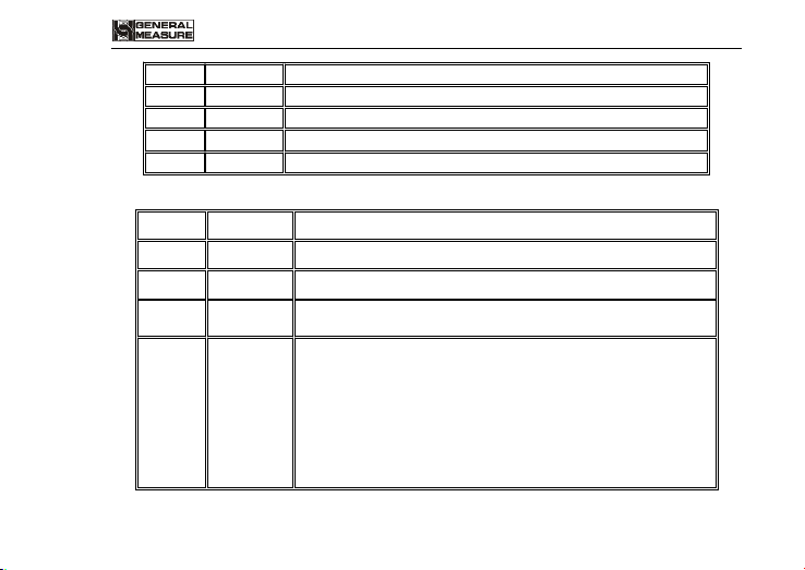
31
F3.4
20000
Maximum capacity output
F3.5
20020
Maximum output
F4
Null
The fourth major term of working parameter.
F4.1
OFF
Parameters password setting switch.
F4.2
000000
Parameters password setting:Valid when F4.1 is ON
4.4 Set point parameters
Code
Default
Description
P1-P4
Null
The first term of working parameters
PX.1
OFF
Change of state if need stable
PX.2
0.0
Change of state minimum duration
PX.3
P1.3=1
P2.3=5
P3.3=0
P4.3=0
Condition of validity:
0:forbid;
1:<;
2:<=;
3:==;
4:>=;
5:>;
M02 Digital Indicator
Page 37
32
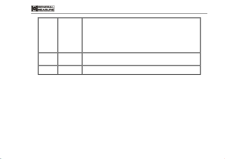
6:!=;compare to minimum value
7:_<>_outside the range, need to set 2 edge value
8:=<__>=inside the range, need to set 2 edge value
9:external trigger. If it’s IO,do 1 state change for 1
trigger, if it’s command, then decide according to
valid or invalid command.
PX.4
0
Set value 1( Set value 1 and set value 2, choose the
minimum to compare)
PX.50Set value 2
Set point has 4 major terms which are user defined.
M02 Digital Indicator
Page 38
33
5 I/O Definition
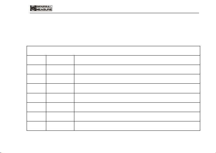
Output
Code
Definition
Description
O0
None
No definition
O1
Stable
Effective output in stable status.
O2
Overflow
Effective output when overflow.
O3
Sp1
Effective output when set point 1 status output.
O4
Sp2
Effective output when set point 2 status output.
O5
Sp3
Effective output when set point 3 status output.
O6
Sp4
Effective output when set point 4 status output.
5.1 I/O Definition
Output/Input code table:
M02 Digital Indicator
Page 39
34
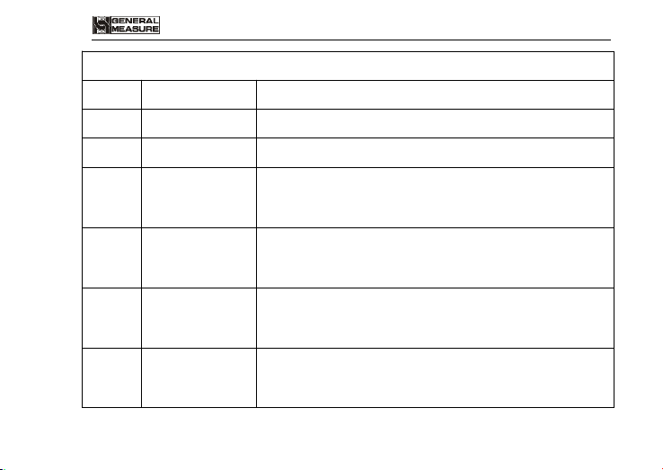
Input
Code
Definition
Description
I0
None
No definition
I1
Zeroing
Effective input for zeroing, pulse input signals
I2
Sp1
If this signal is valid, Sp1 status will be regarded as
invalid. Output valid state when comparision condition
turns to invalid, and be effective again.
I3
Sp2
If this signal is valid, Sp2 status will be regarded as
invalid. Output valid state when comparision condition
turns to invalid, and be effective again.
I4
Sp3
If this signal is valid, Sp3 status will be regarded as
invalid. Output valid state when comparision condition
turns to invalid, and be effective again.
I5
Sp4
If this signal is valid, Sp4 status will be regarded as
invalid. Output valid state when comparision condition
turns to invalid, and be effective again.
M02 Digital Indicator
Page 40
35
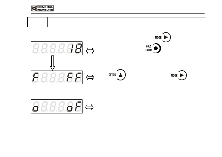
I6
Reset all
Reset all paramater value when this signal is valid.
5.2 I/O testing
Under weighing status,press (5 times),then
display TESTio, press enter into I/O testing
interface.
Normal Status
Press OUT1 status flash, press OUT2
status flash.
This interface shows:IN1 input valid, OUT1 output valid.
M02 Digital Indicator
Page 41
36
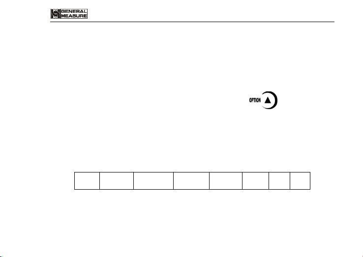
※Under main display(display weight value), long press to enter into serial
communication checking interface, it will display ‘------’ if no communication, and ‘------’
will flash if there’s communication.
STX
Scale
no.
Channel
no.
Status
Value
CRCCRLF
M02 Digital Indicator
6 Serial Communication
M02 has RS232 or RS485 as optional to realize communication with upper
computer。Support r-Cont、r-SP1、Modbus(bus)、tt TOLEDO、Cb920、rECont
protocols and rErEAD protocol.
Serial communication terminal please refer to chapter 2.4.2、2.4.3. Baud rate and
communication format setting please refer to F2.2、F2.3 and F2.4.
6.1 r-Cont
Indicator will send weighing data to host computer without command.
Data Format:
Here:
STX —— 1bit,start character 02H
Scale no. —— 2bits,00~99
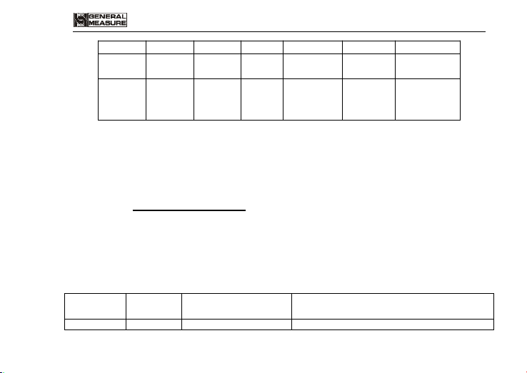
Status —— 2bits,high byte:40H;low byte definition as follows:
Page 42
37
D6D5D4D3D2D1D0
Null
Null
G./N.
weight
+/-
Zero
point
OFL
Stable
100
0:+
1:-
0:
non/zero
1:zero
0:
normal
1:OFL
0:not
stable
1:stable
Operation
code
Para. code
Para. Name
number of character
RWTRead current status
8
Weight Value —— 6 bits;when weight is+(-)overflow,return to“space space OFL
space”
CRC —— 2 bits,check sum
CR —— 1 bit,0DH
LF —— 1 bit,0AH
For example:
02 30 31 31 40 4120 20 20 37 30 30 32 34 0D 0A
Means: stable,positive data,present weight 700
6.2 r-SP1
Code : ASCII
Operation code supported: W,write;R, read;C,calibrate;O, zero
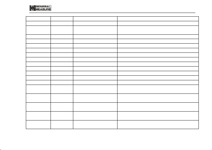
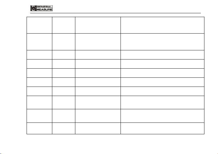
6.2.1 Parameters Code Chart
M02 Digital Indicator
Page 43
38
and weight
RSPRead set point status
4
W
DC
Write mini. Divistion and
max. capacity
8
R/WPTDecimal point digit
1
RDDMinimum division
2
RCPMaximum capacity
6
R/WACAuto. Zeroing switch
1
R/WTRZero tracking range
1
R/WMRStable range
1
R/WZRZeroing range
2
R/WFLdigital filtering para.
1
R/WVCsteady filtering
1
R/WADAD sample rate
1
RPOSet point output status
4
R/W
P1M~P4M
Set point to judge if
need stability
1
R/W
P1T~P4T
Set point minimum
duration time
3
R/W
P1F~P4F
Set point comparison
condition to judge
1
R/W
P1L~P4L
Set point lower edge
value to judge
6
R/W
P1H~P4H
Set point upper edge
value to judge
6
M02 Digital Indicator
Page 44
39
RAMAbsolute millivolt
7: D6D5D4D3D2D1D0;
D6:+;D5-D0: corresponding ASCII for 6 digits
millivolt,Decimal point is fixed to 3 digits
RRMRelative zero point on
millivolt
7:D6D5D4D3D2D1D0
D6 : +/-;D5-D0:corresponding ASCII for 6
digits,Decimal point is fixed to 3 digits
CZYZero calibration with
weight
CZNZero calibration
without weight
6
CGYGain calibration with
weight
6
CGNGain calibration
without weight
12
OCZZero clearing
command
O
P1S~
P4S
Setting the
corresponding set
point
Valid when 9,command valid when external
trigger and 1 status change for 1 external
Trigger
O
P1C~P4CClear the
corresponding set
point
R
ID
Read ID No.
6
M02 Digital Indicator
Page 45
40
1:CRC check error
2:Operation code error
3:Parameters code error
4:Write data error
5:Operation invalid
6:Channel no. error
Note:Default channel no. of this indicator : 1(31H)
STX
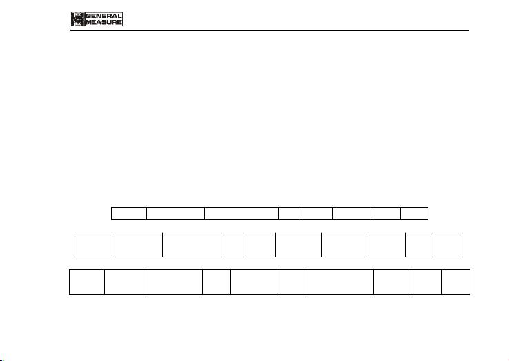
Scale no.
Channel No.
RWTCRCCRLF
STX
Scale
no.
Channel
No.
RWTStatus
Value
CRCCRLF
STX
Scale
no.
Channel
No.
RWTE
Error code
CRCCRLF
Here:
M02 Digital Indicator
6.2.2 Error Code Explanation
6.2.3 Command
Indicator will send weighing data to host computer after received command.
6.2.3.1 Host computer read present status
Send command:
Correct response:
Wrong response:
Page 46
41
D6D5D4D3D2D1D0
Null
Null
G./N.
weight
+/-
Zero point
OFL
Stable
100
0:+
1:-
0:non/zero
1:zero
0:normal
1:OFL
0:not stable
1:stable
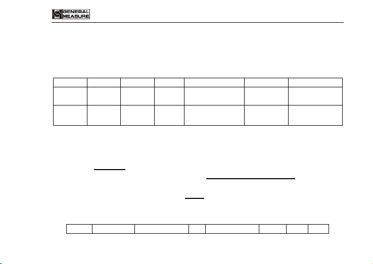
STX
Scale no.
Channel No.
R
Para. code
CRCCRLF
M02 Digital Indicator
STX —— 1bit,start character,02H
R——1 bit,52H
WT——2 bit,57H 54H
E——1 bit,45H
Status —— 2bits,high byte: 40H;low byte definition as follows:
Weight Value —— 6 bits ; when weight is+ ( - )overflow,return to“space space OFL
space”
For example:
02 30 31 31 52 57 54 30 31 0D 0A
Correct response : 02 30 31 31 52 57 54 40 4130 30 33 37 35 33 33 36 0D 0A
(stablepresent value 3753)
Wrong response: 02 30 31 31 52 57 54 45 31 31 39 0D 0A(CRC check error)
6.2.3.2 Read other parameters
Send command:
Page 47
42
STX
Scale no.
Channel No.
R
Para. code
Value
CRCCRLF
STX
Scale
no.
Channel
No.
R
Para.
code
E
Error code
CRCCRLF
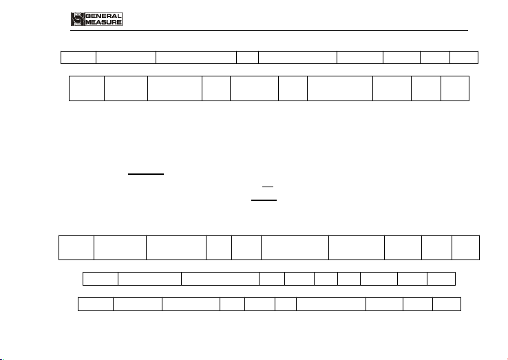
Here:
STX
Scale
no.
Channel
No.
WDCDivision
value
Max.
capacity
CRCCRLF
STX
Scale no.
Channel No.
WDCOKCRCCRLF
STX
Scale
Channel
WDCE
Error code
CRCCRLF
M02 Digital Indicator
Correct response:
Wrong response:
Para. Value—— 1bit
Para. code——2 bits,
For example:
02 30 31 31 524D52 3839 0D 0A
Correct response:02 30 31 31 52 4D 52 36 34 33 0D 0A(stable range:6)
Wrong response:02 30 31 31 53 4D 52 45 32 30 39 0D 0A(Operation code error)
6.2.3.3 Write max. Capacity and min. Division
Send command:
Correct response:
Wrong response:
Page 48
43
no.
No.
STX
Scale
no.
Channel
No.
W
Para.
code
Para.
value
CRCCRLF
STX
Scale
no.
Channel
No.
W
Para.
code
OKCRCCRLF
STX
Scale
Channel
W
Para.EError
CRCCRLF
M02 Digital Indicator
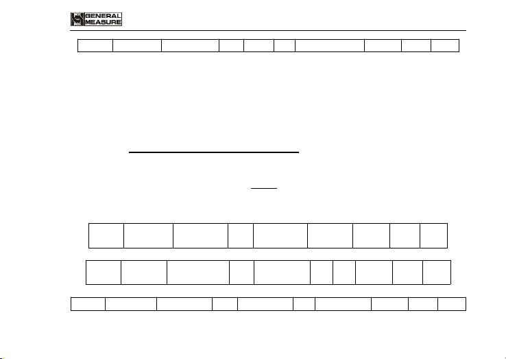
Here:
DC——2 bits,44H 43H
O——1 bit,4FH
K——1 bit,4BH
Division value——2 bits,1/2/5/10/20/50
Max. capacity——6 bits
For example:
02 30 31 3157 44 43 30 35 30 31 30 30 30 30 36 30 0D 0A(division value 5, Max
capacity 10000)
Correct response: 02 30 31 31 57 44 43 4F 4B 32 34 0D 0A
Wrong response: 02 30 31 31 57 44 43 45 35 39 32 0D 0A(Operation can’t execute)
6.2.3.4 Write other parameters
Send command:
Correct response:
Wrong response:
Page 49
44
no.
No.
code
code
STX
Scale no.
Channel No.
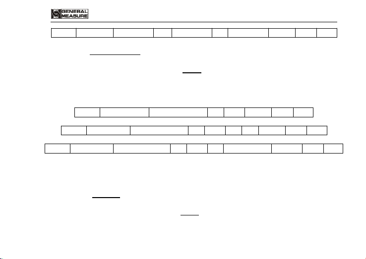
CZYCRCCRLF
STX
Scale no.
Channel No.
CZYOKCRCCRLF
STX
Scale no.
Channel No.
CZYE
Error code
CRCCRLF
M02 Digital Indicator
For example:
02 30 31 3157 5A 52 35 30 30 38 0D 0A(Write zeroing range to 50)
Correct response: 02 30 31 31 57 5A 52 4F 4B 36 31 0D 0A
Wrong response: 02 30 31 31 57 5A 53 45 33 32 38 0D 0A(Para. Code error)
6.2.3.5 Calibration Zero
1)Calibrate zero as per current weight(with weight)
Send command:
Correct response:
Wrong response:
Here:
Z——1 bit,5AH
Y——1 bit,59H
For example:
02 30 31 31 435A 59 39 34 0D 0A
Correct response:02 30 31 31 43 5A 59 4F 4B 34 38 0D 0A
Wrong response:02 30 31 34 43 5A 59 45 36 32 30 0D 0A(channel no. error)
2)Input millivolt calibration zero in the chart(without weight)
Page 50
45
STX
Scale no.
Channel No.
CZNZero millivolt value
CRCCRLF
STX
Scale no.
Channel No.
CZNOKCRCCRLF
STX
Scale no.
Channel No.
CZNE
Error code
CRCCRLF
STX
Scale no.
Channel No.
CGYWeight value
CRCCRLF
STX
Scale no.
Channel No.
CGYOKCRCCRLF
STX
Scale no.
Channel No.
CGYE
Error code
CRCCRLF
M02 Digital Indicator
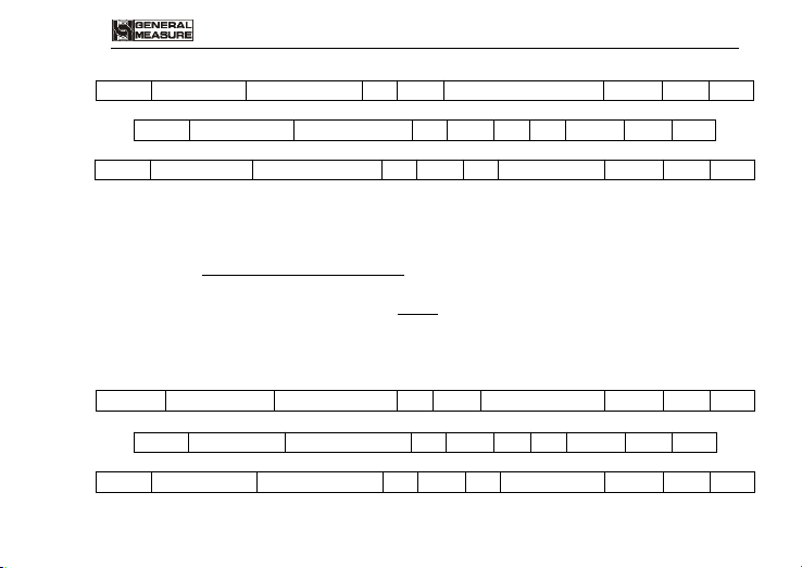
Send command:
Correct response:
Wrong response:
Here:
ZN——2 bits,5AH4EH
Zero millivolt value——6 bits
For example:
02 30 31 31 43 5A 4E 30 31 32 36 31 30 38 31 0D 0A
Correct response:02 30 31 31 43 5A 4E 4F 4B 33 37 0D 0A
Wrong response:02 30 31 31 43 5A 4E 45 34 30 34 0D 0A(Write data error)
6.2.3.6 Gain calibration
1)With weights
Send command:
Correct response:
Wrong response:
Page 51
46
STX
Scale no.
Channel No.
CGNGain millivolt
Weight value
CRCCRLF
STX
Scale no.
Channel No.
CGNOKCRCCRLF
STX
Scale no.
Channel No.
CGNE
Error code
CRCCRLF
M02 Digital Indicator
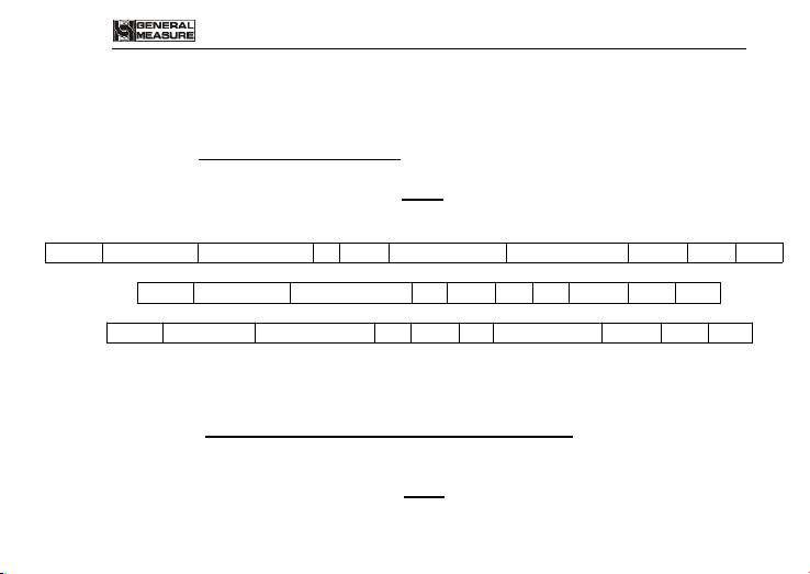
Here:
GY——2 bits,47H 59H
Weight value——6 bits: Write in weight value
For example:
02 30 31 3143 47 59 30 30 30 32 30 30 36 35 0D 0A(Write in: weight value 200)
Correct response: 02 30 31 31 43 47 59 4F 4B 32 39 0D 0A
Wrong response: 02 30 31 35 43 47 59 45 36 30 32 0D 0A(Channel no. error)
2)Without weights
Send command:
Correct response:
Wrong response:
Here:
Gain millivolt——6 bits
Weight value——6bits
For example:
02 30 31 3143 47 4E 30 30 31 39 34 30 30 30 30 32 30 30 35 36 0D 0A (Write in:
weight value 200,corresponding gain millivolt 0.194)
Correct response: 02 30 31 31 43 47 4E 4F 4B 31 38 0D 0A
Wrong response: 02 30 31 31 43 48 4E 45 33 38 35 0D 0A(Para. Code error)
Page 52
47
STX
Scale no.
Channel No.
OCZCRCCRLF
STX
Scale no.
Channel No.
OCZOKCRCCRLF
STX
Scale no.
Channel No.
OCZE
Error code
CRCCRLF
023031314F435A38340D0
A
M02 Digital Indicator
6.2.3.7 Zeroing
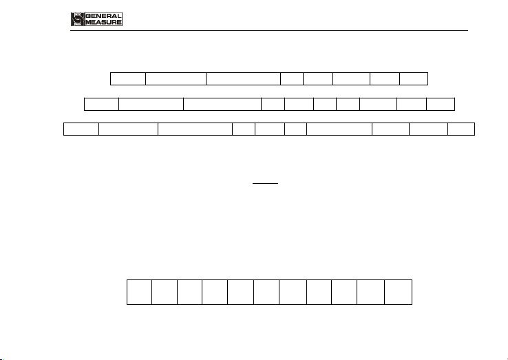
Send command:
Correct response:
Wrong response:
For example:
02 30 31 31 4F 43 5A 38 34 0D 0A
Correct response: 02 30 31 31 4F 43 5A 4F 4B 33 38 0D 0A
Wrong response: 02 30 31 31 4F 43 5A 45 35 30 36 0D 0A(Operation can’t execuate)
6.2.3.8 CRC computation
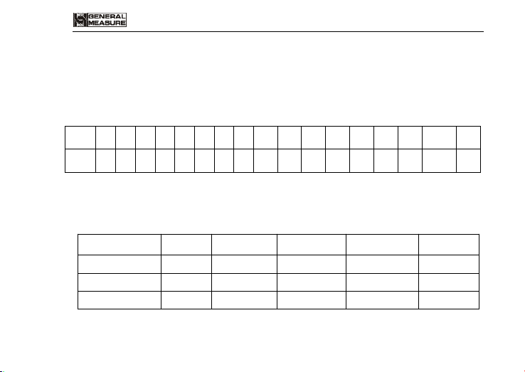
All the values in front of the parity bit add together and convert to decimal data,
then convert the last 2 bits to ASCII code (decade in front and the unit at the back).
For example
The following is a frame of data:
Add 02~5A: 180(Hex),convert to decimal data: 384. We can calculate from this
Page 53
48
When choose “tt” protocol in working parameter F2.3, indicator will send datas in
continuous mode with TOLEDO protocol.
Continuous sending mode format as below:
1234567891011121314151617
18
STX
0D
Here:start character is standard ASII start character 02(STX)
D00101
0
D11100
1
D20011
0
Decimal point
x.x.xx
.xxx
.xxxx
M02 Digital Indicator
that the check code is 38,34 for the data frame.
6.3 tt TOLEDO Protocol
︸ A B C display weight(6 bits) 6 个 30H Checksum
status byte A definition as below:
D3 D4 D6 为 0(not change) D5 is 1(not change)
Page 54
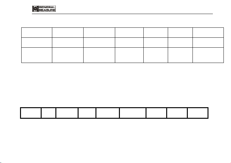
49
D6D5D4D3D2D1D0
Status
Stable
Overflow
symbol
G.W.
Is 0
(not change)
Is 1
(not change)
Is 1
(not change)
1-unstable
0-stable
1-overflow
0-normal
1-negative
0-positive
Is 0
(not change)
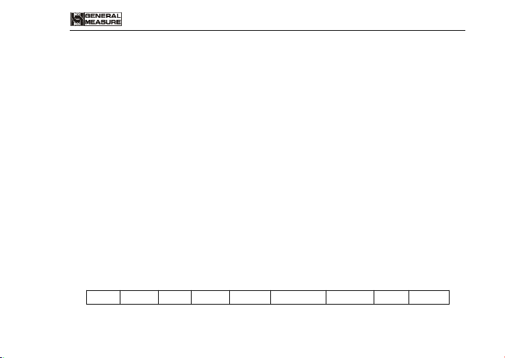
When F2.3=Cb920 in working parameter, indicator will send weighing data
continuously without command under Cb920 protocol.
Status,G.W.
0/1
Symbol
Display
UnitCRLF
Here:
Status —— 2 bits,OL:( 4FH 4CH ) OFL;ST:( 53H 54H )Stable;US:( 55H
53H )unstable
M02 Digital Indicator
status byte B definition as below:
status byte C is reserved, output 20H.
6.4 Cb920
Data format:
Page 55
50
,—— 1 bit,separator 2CH
G.W. —— 2 bits, GS: gross weight 47H 53H
0/1 —— 1 bit,(30H/31H) interleaved transmission
Symbol —— 1 bit, 2BH(+), 2DH(-)
Display —— 7 bits,including decimal point
Unit —— 2 bits,blank space(20H 20H)
CR —— 1 bit,0DH
LF —— 1 bit,0AH
For example: When indicator send the following automatically:
53 54 2C 47 53 31 2B 20 20 31 39 30 2E 31 20 20 0D 0A
Means: Stable、G.W.、Data value is positive、current weight is 190.1
Indicator will send weighing data to the upper computer continuously without any
command.
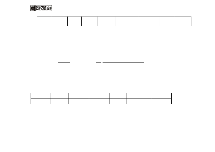
Return data frame format specification:
Status,GS,+/-
Display
UnitCRLF
M02 Digital Indicator
6.5 rECont
Page 56
51
2bits
2C
47 53
2C
2B/2D
7bits
6B 67
0D
0A
Status —— 2 bits,OL(OFL):4FH 4CH; ST(stable):53H 54H; US(unstable):55H 53H
Display value —— 7bits, including decimal point, high bit is blank if no decimal point.
For example: When indicator send the following automatically:
53 54 2C 47 53 2C 2B 30 31 31 2E 31 32 30 6B 67 0D 0A
Means:Stable,Data value is positive,display value is 11.120kg
Indicator will send weighing data to the upper computer under command.
Data format:
DataREADCRLF
explain
52H
45H
41H
44H
0DH
0AH
The return data frame is the same with that of rECont protocol, please refer to rECont.
M02 Digital Indicator
Here:
6.6 rEREAD
1) Zero clearing command: ZERO ON<CR><LF> : 5A 45 52 4F 20 4F 4E 0D 0A
Return YES<CR><LF> or NO? <CR><LF>
Page 57
52
2) Calibration zeroing command: TARE ON<CR><LF> : 54 41 52 45 20 4F 4E 0D 0A
Function code
Definition
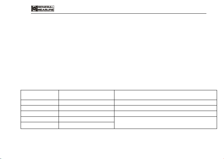
Description
03
read the register
06
preset single register
16
preset several registers
Command only support preset double registers.
01
read coil
The length unit is bit.
05
write coil
Return YES<CR><LF> or NO? <CR><LF>
3) Read ID no.: GET ID<CR><LF> : 47 45 54 20 49 44 0D 0A
Return ASCII code with 6 digits ID no.
6.7 Modbus
Indicator uses RTU mode to communicate, every 8-bit byte of the message are
divided into 2pcs of 4-bit hexadecimal characters to transmit at binary code.
Code: Binary
Function code:
Exception code response
M02 Digital Indicator
Page 58
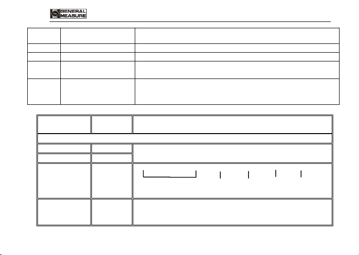
53
Code
Definition
Description
02
Illegal data address
Data address received from error code is not allowed
03
Illegal data value
Data wrote in is not in permissible range
04
machine fault
When indicator is trying to execuate operation required,
unrecoverable error is produced.
07
Unsuccessful
programming
request
Command received can’t be execuated under current
condition.
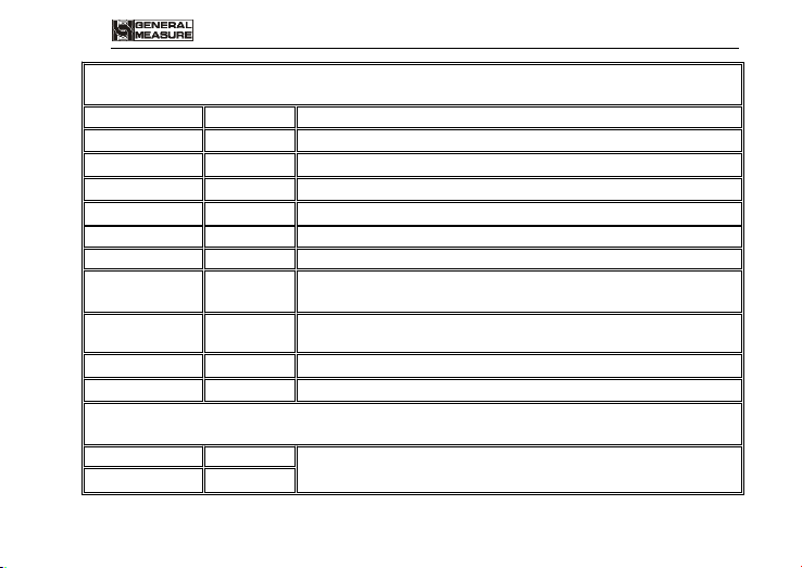
6.7.1 Modbus communication address
PLC addr.
Display
addr.
Description
The following items are only-read register(code 0x03)
40001
0000
Present weight value(4bits including sign characters, the
high bit is in the front)
40002
0001
40003
0002
D15—D14..D5—D4 — D3—— D2 ——D1——D0
All is 0 0:+ 0:non-zero 0:normal 0:unstable
1:- 1: zero 1:OFL 1:stable
40004
……
40006
0003
……
0005
Reserve(permit to read, reading value is 0 )
M02 Digital Indicator
Page 59
54
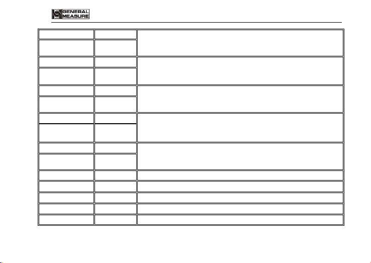
The following items are two bytes and are available to read and write
(write code 0x06,read code 0x03)
40007
0006
Zeroing(zeroing when write in non-zero value)
40008
0007
Automatically zeroing when power on(0:OFF;1:ON)
40009
0008
Zero tracking range(0-9d)
40010
0009
Stable range(1-9d)
40011
0010
Zeroing range(0%-99%)
40012
0011
Digit filter parameters(0-9)
40013
0012
Stability filter series(0-9)
40014
0013
AD sample rate:0:15/s 1:30/s 2:60/s 3:120 /s
4:480/s 5:960/s
40015~
40018
0014~
0017
Reserved
40019
0018
Decimal point place(0:0bit,1:1bit,2:2bits,3:3bits,4:4bits)
40020
0019
Minimum division(1/ 2/ 5/ 10/ 20/ 50)
The following items are available to read and write
(writing code 0x10,read code 0x03)
40021
0020
Maximum capacity(max.capacity≤mini.division×100000)
40022
0021
M02 Digital Indicator
Page 60
55
40023
0022
Zero calibration with weights: write in 1 and calibrate zero
with the current weight.
Read: Absolute millivolt of current load cell
40024
0023
40025
0024
Zero calibration without weights: Write millivolt value at
zero;Write in range(load cell 3mV/V:millivolt value range
within 0.02-12.000mV) millivolt value at zero when read.
40026
0025
40027
0026
Gain calibration with weights. Write weight value(≤max.
capacity). Return millvolt at present weight value when
read
40028
0027
40029
0028
Gain calibration without weights ; input gain millivolt(load
cell 3mV/V:0.000 < millivolt<15.000mV - zero
millivolt).Read: millivolt value for gain calibration.
40030
0029
40031
0030
Gain calibration weight without weights. input gain
millivolt(≤max. capacity) Read: weight value for gain
calibration.
40032
0031
40033~40040
0032~0039
reserved
40041
0040
Set point 1 stable or not(0:no;1:yes)
40042
0041
Set point 1 min. duration time(0-999 : 0-99.9sec.)
40043
0042
Set point 1 valid condition
40044~40045
0043~0044
Set point 1 set value 1
M02 Digital Indicator
Page 61
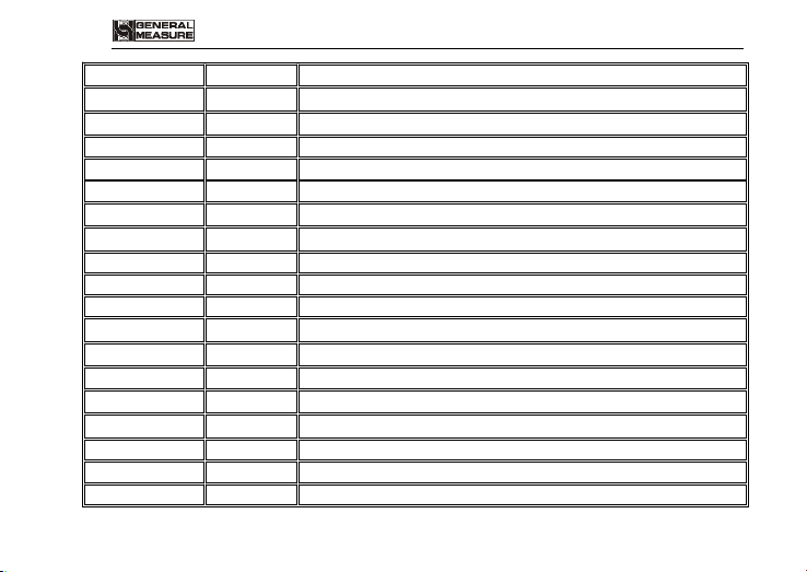
56
40046~40047
0045~0046
Set point 1 set value2
40048
0047
Set point 2 stable or not(0:no;1:yes)
40049
0048
Set point 2 min. duration time(0-999 : 0-99.9sec.)
40050
0049
Set point 2 valid condition
40051~40052
0050~0051
Set point 2 set value1
40053~40054
0052~0053
Set point 2 set value2
40055
0054
Set point 3 stable or not(0:no;1:yes)
40056
0055
Set point 3 min. duration time(0-999 : 0-99.9sec.)
40057
0056
Set point 3 valid condition
40058~40059
0057~0058
Set point 3 set value 1
40060~40061
0059~0060
Set point 3 set value 2
40062
0061
Set point 4 stable or not(0:no;1:yes)
40063
0062
Set point 4 min. duration time(0-999 : 0-99.9sec.)
40064
0063
Set point 4 valid condition
40065~40066
0064~0065
Set point 4 set value 1
40067~40068
0066~0067
Set point 4 set value 2
40069
0068
Output 1 user-defined
40070
0069
Output 2 user-defined
40071
0070
Input 1 user-defined
M02 Digital Indicator
Page 62
57
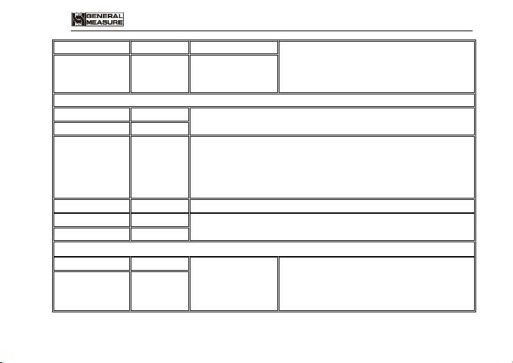
40072
0071
I/O output value
Note: available only when coil address
00016 is valid.
Input write 1 valid,0 invalid.
Read 1 valid,0 invalid
40073
0072
I/O input value
Reserved
40401
0400
Current weight value( 4 bytes with symbolic number,
high digit in front)
40402
0401
40403
0402
D15—D14……D4 0
D3 0:+ 1:D2 0:non-zero 1:zero
D1 0:normal 1:OFL
D0 0:Stable 1:Unstable
40404
0403
0
40405
0404
6 digits without symbolic number, user ID no.
40406
0405
The following items are bit read only. (read code: 0x03)
49001
9000
Version no.
If display10024 ,formatXX XXXX,main
version no., hardware no., software
no..So main version no.01 , hardware
no. 00,software no. 24
49002
9001
M02 Digital Indicator
Page 63
58
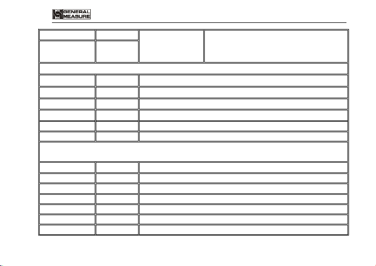
49003
9002
Develop time
If display 141024, means 24thOct.,
2014
49004
9003
The following items are bit read only. (read code:0 x 0 1)
00001
0000
0:unstable; 1:stable
00002
0001
0:normal;1:OFL
00003
0002
0:non-zero;1:zero
00004
0003
0:+;1:-
00005
0004
Reserved
00006
0005
Reserved
The following item are available to read and write
(read code:0x01,writing code: 0x05)
00007
0006
Automatically zeroing when power on(0:OFF; 1:ON)
00008
0007
Reserved
00009
0008
Reserved
00010
0009
Reset all
00011
0010
Reset calibration
00012
0011
Reset paramaters
00013
0012
Reset I/O
M02 Digital Indicator
Page 64
59
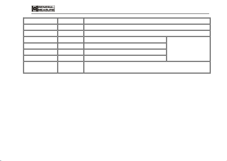
00014
0013
Reserved
00015
0014
Reserved
00016
0015
I/O testing switch
00017
0016
Set point 1 status
Only read:
0:invalid,1:valid
00018
0017
Set point 2 status
00019
0018
Set point 3 status
00020
0019
Set point 4 status
00021~
00032
0020~
0031
Reserved
M02 Digital Indicator
Page 65
60
M02 Digital Indicator
7 Password Input and Setting, Reset
7.1 Password Input
(1)Indicator calibration and working paraters setting default password: 000000.
(2)User can set password in parameters when F4.1 is“ON”.
(3)When display is “PASS”, need to input correct password to enter parameters.
Note:
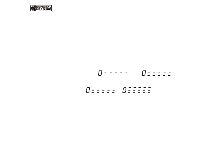
(1)When input password, if first time wrong, it will go to the second chance for
password input(display from turn to ).
(2)If second input wrong, it will enter into interface for inputting password the third
time
(Display change from to ).
(3 ) If Input wrong for three times, main display show “Error4” and self-lock, but user
can operate when power on again.
7.2 Password Setting
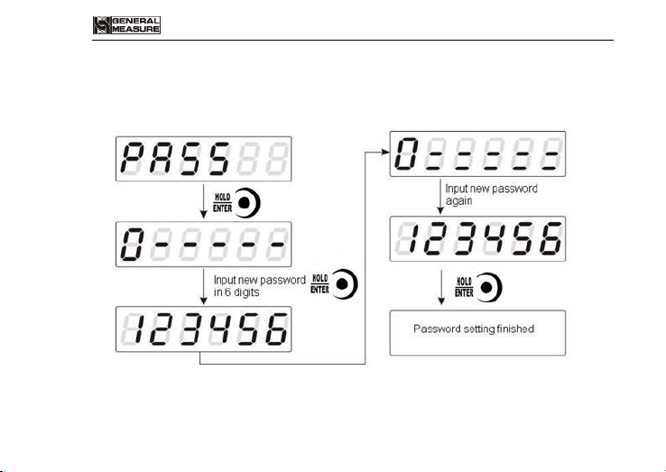
(1)User can set password in parameters when F4.1 is“ON”.
Page 66
61
M02 Digital Indicator
(2) User must input same new password twice in setting password,If not same, main
display show“Error”one second and return to PASS again.
Page 67
62
7.3 Factory Reset
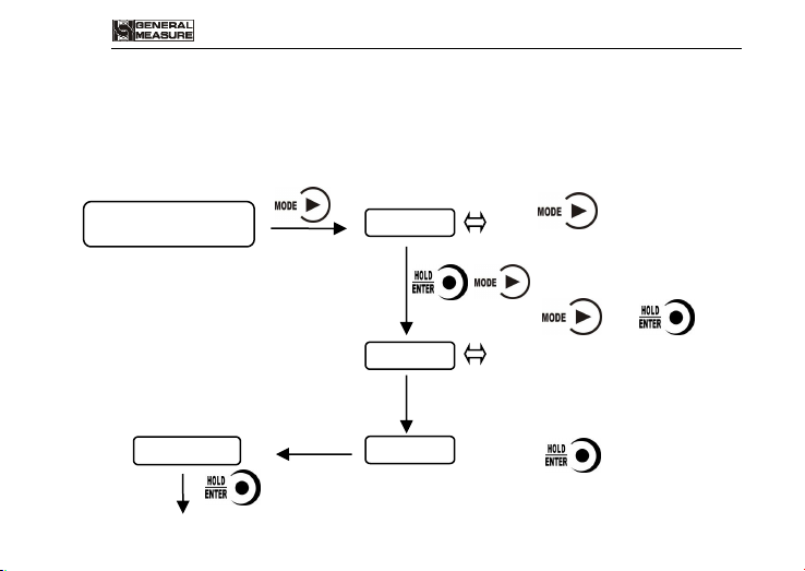
In working status,
press 1 time to display
SET UP.
Normal working status
SET UP
Press and the
same time to display‘PASS’,
then password input.
PASS
0----
Password input interface, input
fixed password 880202, then
press save password
and enter parameter reset.
880202
Note: Factory reset is only for special technicists, which will reset all of
parameters and will maybe cause not working.
Take reset all for example:
M02 Digital Indicator
Page 68
63
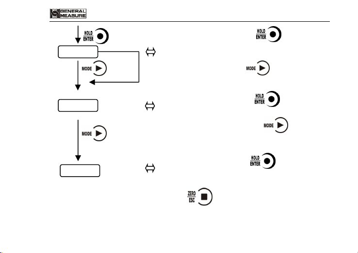
1 ) In F SEt interface, press to reset working
parameters, enter into reset calibration paramters
interface.
2)In F SEt interface, press ,not to make working
parameter reset, enter into calibration para. Reset
interface.
F SEt
F
F
1) In F CAL interface, press to reset calibration
para., enter into reset all interface.
2 ) In F CAL interface, press , not to make
calibration para. reset, enter into reset all interface.
1)In F ALL interface, press to make reset all of
the paramters ( including working para., calibration
para., I/O etc..
Note: In all reset interfaces, press to exit and return to weighing
interface.
M02 Digital Indicator
Page 69
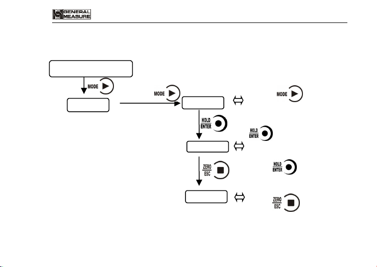
64
8 Display Testing
The following flow chart is to test lights on main-display and status lights.
Normal weighing status
SEtUP
tESt
Press 5 times
8.8.8.8
Under parameter interface,
press to switch
to“tESt”interface.
Under“tESt”interface,press
to make display testing,
Nixie tube display and indicator
lights all shine. Now if
press , display will
sparkle.
After testing is finished,
press to return
to“tESt”interface.
tESt
M02 Digital Indicator
Page 70

65
M02 Digital Indicator
9 Errors and Alarm Messages
Error ①Input error.
②wrong data beyond parameter range.
Error 2 The present weight value is out of zeroing range.
Error 3 Scale platform is not stable when zeroing.
Error 4 Input wrong password more than 3 times.
OFL Weighing value is positive overflow.
-OFL Weighing value is negative overflow.
Page 71
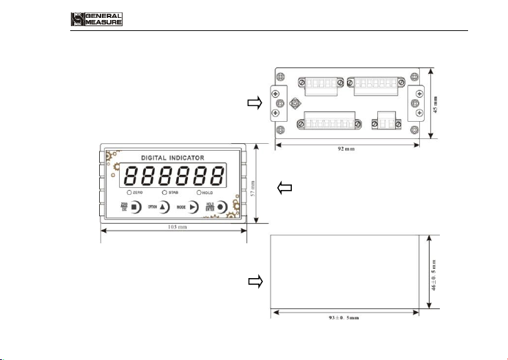
66
10 Dimension of Indicator
Dimension of rear panel:92×45(mm)
Dimension of front panel:105×57(mm)
Panel cutout dimension:93×46(mm)
M02 Digital Indicator
 Loading...