


Powerful 2 HP motor with thermal overload
protection.
Front and rear fold-down extension tables
(12 L x 15 1/4 W) with end rollers for
smooth easy stock feeding.
Top mounted return rollers for smooth
stock handling for consecutive
planning/multiple passes.
Convenient power cord storage brackets
and inset lifting handles.
Dual position depth of cut adjustment
handle mounts left or right – one full
rotation equals 1/16”.
Dual feed speeds for smooth planning
with either soft or hard wood.
Adjustable pre-set depth gauge for
accurate repeat cuts.
Easy to read graduated scale in both
inches and metric indicates workpiece
thickness.
Safety On/Off switch with key. Unit cannot
be started when key is removed from
switch.
Snipe eliminating head lock.
Depth of cut indicator.
Includes magnetic knife setting guide.
TABLE AREA WITH EXTENSIONS (L X W)
36 5/8” X 15 1⁄4” (930 x 387 mm)
MAXIMUM PLANING
WIDTH
13” (330 mm)
MAXIMUM
THICKNESS OF STOCK
6” (152 mm)
MINIMUM
THICKNESS OF STOCK
1⁄8” (3 mm)
MINIMUM LENGTH OF ST
OCK
5” (127 mm)
MAXIMUM DEPTH OF CUT (FULL
WIDTH)
1⁄16” (1.5 mm)
KNIVES
2 - DOUBLE EDGED
CUTTERHEAD SPEED
9500 RPM
FEED SPEEDS (2)
18 & 26 FPM
CUTS PER INCH
88 / 61
MO
TOR
2 HP, 120 V, 1 Ph, 15 A
REVISION 1 - JUNE 7/07
© COPYRIGHT GENERAL INTERNATIONAL 06/2007

THANK YOU
for choosing this General® International model 30-010 M1
13” single surface planer.This planer has been carefully tested and inspected before shipment
and if properly used and maintained, will provide you with years of reliable service. To ensure
optimum performance and trouble-free operation, and to get the most from your investment,
please take the time to read this manual before assembling, installing and operating the unit.
The manual’s purpose is to familiarize you with the safe operation, basic function, and features
of this planer as well as the set-up, maintenance and identification of its parts and components. This manual is not intended as a substitute for formal woodworking instruction, nor to
offer the user instruction in the craft of woodworking. If you are not sure about the safety of
performing a certain operation or procedure, do not proceed until you can confirm, from
knowledgeable and qualified sources, that it is safe to do so.
Once you’ve read through these instructions, keep this manual handy for future reference.
All component parts of General® International machinery are carefully tested and inspected during all stages of
production, and each machine is thoroughly inspected upon completion of assembly. Because of our commitment to quality and customer satisfaction, General® International agrees to repair or replace, within a period of 24
months from date of purchase, any genuine part or parts which, upon examination, prove to be defective in workmanship or material. In order to obtain this warranty, all defective parts must be returned freight pre-paid to
General® International Mfg. Co., Ltd. Repairs attempted without our written authorization will void this warranty.
GENERAL ® INTERNATIONAL WARRANTY
Disclaimer:
The information and specifications in this manual pertain to
the unit as it was supplied from the factory at the time of printing.
Because we are committed to making constant improvements, General
International reserves the right to make changes to components, parts
or features of this unit as deemed necessary, without prior notice and
without obligation to install any such changes on previously delivered
units. Reasonable care is taken at the factory to ensure that the specifications and information in this manual corresponds with that of the unit
with which it was supplied. However, special orders and “after factory”
modifications may render some or all information in this manual
inapplicable to your machine. Further, as several generations of this
model of planer and several versions of this manual may be in circulation, if you own an earlier or later version of this unit, this manual may not
depict your machine exactly. If you have any doubts or questions
contact your retailer or our support line with the model and serial number of your unit for clarification.
GENERAL® INTERNATIONAL
8360 Champ-d’Eau, Montreal (Quebec) Canada H1P 1Y3
Telephone (514) 326-1161 • Fax (514) 326-5555 • www.general.ca

1. Read, understand and follow all safety warnings and
instructions in the supplied Operator’s Manual.
2. Do not operate the planer when tired, distracted, or
under the effects of drugs, alcohol or any medication
that impairs reflexes or alertness.
3. The working area should be well lit, clean and free of
debris.
4. Keep children and shop visitors at a safe distance
when the planer is in operation; do not permit them to
operate the planer.
5. Childproof and tamper proof your shop and all machinery with locks, master electrical switches and
switch keys, to prevent unauthorized or unsupervised
use.
6. Stay alert! Give your work your undivided attention.
Even a momentary distraction can lead to serious
injury.
7. Wear approved safety glasses, dust mask and hearing
protection, and do not wear loose clothing, gloves,
bracelets, necklaces or jewelry while operating the
planer. Wear protective hair covering to contain long
hair and wear non-slip footwear.
8. Fine particulate dust is a carcinogen that can be hazardous to health. Work in a well-ventilated area and
whenever possible use a dust collector.
9. Keep hands well away from the cutterhead and all
moving parts. Do not clear chips and sawdust away
with hands, use a brush.
10. Be sure that wrenches, tools, drinks and other clutter
are removed from the machine and/or the table surfaces before operation.
11. Kickback is when the workpiece is ejected at high
speeds by the force of the cutterhead.To minimize the
risk of injury from kickback, use proper feeding technique and stand to one side, out of the path of a potential kickback.
12. Be sure the blades are securely installed in the cutterhead and in proper cutting direction before operation.
13. Make sure the cutterhead has gained full operating
speed before feeding stock into the planer.
14. Always use clean, properly sharpened knives in the
cutterhead. Dirty or dull knives are unsafe and can
lead to accidents.
15. Inspect stock and remove all foreign objects before
planing. Make sure that any stock you plane is clean
and free of dirt, nails, staples, tiny rocks or any other
foreign objects that may damage the blades. Only
process natural solid wood boards. Never plane MDF,
particle board, plywood, laminates or other synthetic
materials.
16. Do not push or force stock into the cutterhead. The
planer will perform better and safer when working at
the rate for which it was designed.
17. The maximum depth of cut for one pass is 1/8” for a
board of 5 -1/2" or less In width and 1/16" for a board
wider than 5 -1/2". Never attempt to remove more material than the maximum in any single pass.
18. Select appropriate feed speed for the stock being planed: high speed for softwood and slow for hardwoods.
19. Place stock firmly against the table and use suitable
in-feed and out-feed support if stock is too long.
20. Keep guards in place and in working order. If a guard
must be removed for maintenance or cleaning make
sure it is properly attached before using the machine
again.
21. Never leave the machine unattended while running
or with the power “ON”.
22. Always turn off and disconnect from power source
before servicing or changing accessories, blades, or
before performing any maintenance or adjustments.
23. Make sure the switch is in the "off" position before plugging in the power cord.
24. Make sure planer is properly grounded. If equipped
with a 3-prong plug it should be used with a three-pole
receptacle. Never remove the third prong.
25. Use only parts and accessories that are designed for
use with this planer. The use of parts or accessories
NOT recommended by General International may result in equipment malfunction and an increased risk
of injury.
26. Do not use this planer fro anything other than its intended use. If used for other, General International
disclaims any real or implied warranty and holds itself
harmless for any injury which may result from that use.
Rules for Safe Operation
To help ensure safe operation, please take a moment to learn the machine’s applications and limitations, as well as potential hazards. General® International disclaims any real or implied warranty and
holds itself harmless for any injury that may result from improper use of its equipment.

ELECTRICAL REQUIREMENTS
Before connecting the machine to the power source, verify that the voltage of your power supply corresponds
with the voltage specified on the motor I.D. nameplate. A power source with greater voltage than needed can
result in serious injury to the user as well as damage to the machine. If in doubt, contact a qualified electrician
before connecting to the power source.
This tool is for indoor use only. Do not expose to rain or use in wet or damp locations.
GROUNDING INSTRUCTIONS
In the event of an electrical malfunction or short circuit, grounding
reduces the risk of electric shock. The motor of this machine is wired for
110V single phase operation and is equipped with a 3-conductor cord
and a 3-prong grounded plug to fit a grounded type receptacle, . Do
not remove the 3rd prong (grounding pin) to make it fit into an old 2hole wall socket. If an adaptor plug is used, , it must be attached to
the metal screw of the receptacle.
Note: The use of an adaptor plug is illegal in some areas. Check your
local codes.
DO NOT MODIFY THE PLUG PROVIDED.
If it will not fit your receptacle, have the proper receptacle installed by a qualified electrician.
CHECK with a qualified electrician or service person if you do not completely understand these grounding instruc-
tions, or if you are not sure the tool is properly grounded.
EXTENSION CORDS
USE ONLY 3-WIRE EXTENSION CORDS THAT HAVE 3-PRONG GROUNDING PLUGS AND 3-POLE RECEPTACLES THAT ACCEPT
THE TOOLS’ PLUG. REPAIR OR REPLACE A DAMAGED OR WORN POWER CORD OR PLUG IMMEDIATELY.
If you find it necessary to use an extension cord with your machine make sure the cord rating is suitable for the
amperage listed on the motor I.D. plate. An undersized cord will cause a drop in line voltage resulting in loss of
power and overheating. The accompanying chart shows the correct size extension cord to be used based on cord
length and motor I.D. plate amp rating. If in doubt, use the next heavier gauge. The smaller the number the heavier
the gauge.
AMPERES
(AMPS)
EXTENSION CORD LENGTH
25 FEET 50 FEET 100 FEET 150 FEET
< 5
18 16 16 14
6 TO 10 18 16 14 12
10 TO 12 16 16 14 14
12 TO 16 14 12
* NR * NR
* NR = Not Recommended
4
13” SINGLE SURFACE PLANER
30-010
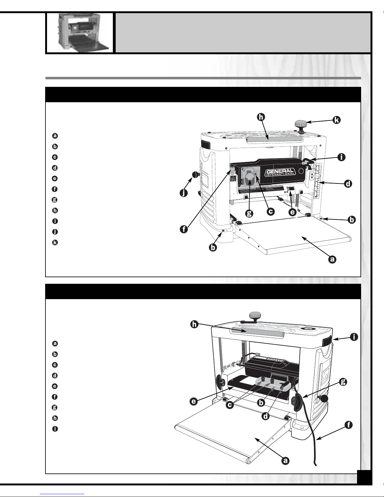
IDENTIFICATION OF MAIN PARTS AND COMPONENTS
IN-FEED TABLE
MOUNTING HOLES
CIRCUIT BREAKER
STOCK THICKNESS SCALE
DEPTH OF CUT INDICATOR
PRESET DEPTH GAUGE
ON/OFF SWITCH
RETURN ROLLER
CUTTERHEAD LOCKING HANDLE
SPEED SELECTION HANDLE
HEIGHT ADJUSTMENT HANDLE
FRONT VIEW
OUT-FEED TABLE
TOOL TRAY
KNIFE SETTING MAGNETS
T-HANDLE WRENCH
CHIP DEFLECTOR
POWER CORD
POWER CORD STORAGE HOOKS
RETURN ROLLER
LIFTING HANDLE
REAR VIEW
5

Carefully unpack and remove the planer and its components from the box and check for damaged or missing
items as per the list of contents below.
NOTE: Please report any damaged or missing items to your
General International distributor immediately.
LIST OF CONTENTS
QTY
PLANER . . . . . . . . . . . . . . . . . . . . . . . . . . . . . . . . . . . . .1
ADJUSTMENT HANDLE . . . . . . . . . . . . . . . . . . . . . . . . .1
FLAT WASHER . . . . . . . . . . . . . . . . . . . . . . . . . . . . . . . .1
PAN HEAD BOLT . . . . . . . . . . . . . . . . . . . . . . . . . . . . . .1
KNIFE SETTING MAGNETS . . . . . . . . . . . . . . . . . . . . . .2
T-HANDLE WRENCH . . . . . . . . . . . . . . . . . . . . . . . . . . .1
POINTER . . . . . . . . . . . . . . . . . . . . . . . . . . . . . . . . . . . .1
6
The unit should be installed on a flat, level, sturdy and
stable surface, able to support the weight of the
machine and the workpiece with ease.
ASSEMBLY INSTRUCTIONS
BEFORE STARTING THE INSTALLATION AND ASSEMBLY, MAKE SURE THAT THE POWER SWITCH IS IN THE “OFF” POSITION
AND THAT THE POWER CORD IS UNPLUGGED. DO NOT PLUG IN OR TURN ON THE PLANER UNTIL YOU HAVE COMPLETED THE INSTALLATION AND ASSEMBLY STEPS DESCRIBED IN THIS SECTION OF THE MANUAL.
For your convenience this planer is shipped from the factory partially assembled and requires only minimal assembly and set up before being put into service.
Never install or operate the planer over the edge of a
table, workbench or other mounting surface.
UNPACKING & SET UP

To accommodate the users personal preference or
work habits the adjustment handle can be installed on
either side of the top of the planer.
ATTACH THE DEPTH OF CUT ADJUSTMENT HANDLE
With the T-Handle wrench,use the supplied washer and
pan head screw to attach the depth of cut adjustment
handle as shown.
Fold down the in-feed and out-feed tables, , and stow the knife setting magnets and T-handle wrench in the holder at the rear of the machine as shown, .
STOW THE KNIFE SETTING MAGNETS AND T-HANDLE WRENCH
7
HEX. HEAD BOLT
FLAT WASHER
PLANER
WORKBENCH OR STAND
FLAT WASHER
LOCK WASHER
HEX. NUT
If a permanent shop placement or installation is practical, consider using the mounting holes and drilling
matching through holes in your workbench or mounting surface to bolt the planer in place (hardware not
included) on your workbench.
If you prefer an optional steel stand (item #30-015)
is available from your local General International
dealer.

The unit is equipped with a circuit breaker located to the right of the power switch,,to protect the motor from
power surges or spikes in line voltage. In the event of a power surge,the circuit breaker will be automatically tripped
thereby cutting off the power to the motor.
To reset the circuit breaker after it has been tripped; set the power switch to the “off”position and depress the reset
button on the circuit breaker as shown,,then restart the machine.
SURGE PROTECTION/CIRCUIT BREAKER
The planer is equipped with a rocker style ON/OFF switch located on the front left hand side of the cutter head, .
To prevent unwanted or unauthorized start-up or usage, remove the lock-out key and store it in a safe place,
,
whenever the planer is not in use. To start the planer, insert the lock-out key and pull up on the lower portion of the
switch as shown, . To stop the planer, push down on the switch,
.
ON/OFF POWER SWITCH
SAFETY KEY
(PREVENTS START-UP
WHEN REMOVED)
POWER ON POWER OFF
TO AVOID UNEXPECTED OR UNINTENTIONAL START-UP BE CERTAIN THAT THE POWER SWITCH HAS BEEN SET TO THE OFF
POSITION BEFORE RE-SETTING THE CIRCUIT BREAKER.
8
BASIC ADJUSTMENTS AND CONTROLS
CONNECTING TO A POWER SOURCE
Once the assembly steps have been completed and the unit is safely secured or installed on a work surface such
as a bench, stand or worktable, uncoil the power cord from the storage brackets, . With the switch in the off position, plug the power cord into an appropriate outlet. Refer back to the section entitled Electr
ical Requirements
and make sure all requirements and grounding instructions are followed. When planing operations have been
completed unplug the unit from the power source and wrap the power cord back onto the storage brackets for
safe storage, .
SWITCH OFF
SWITCH OFF
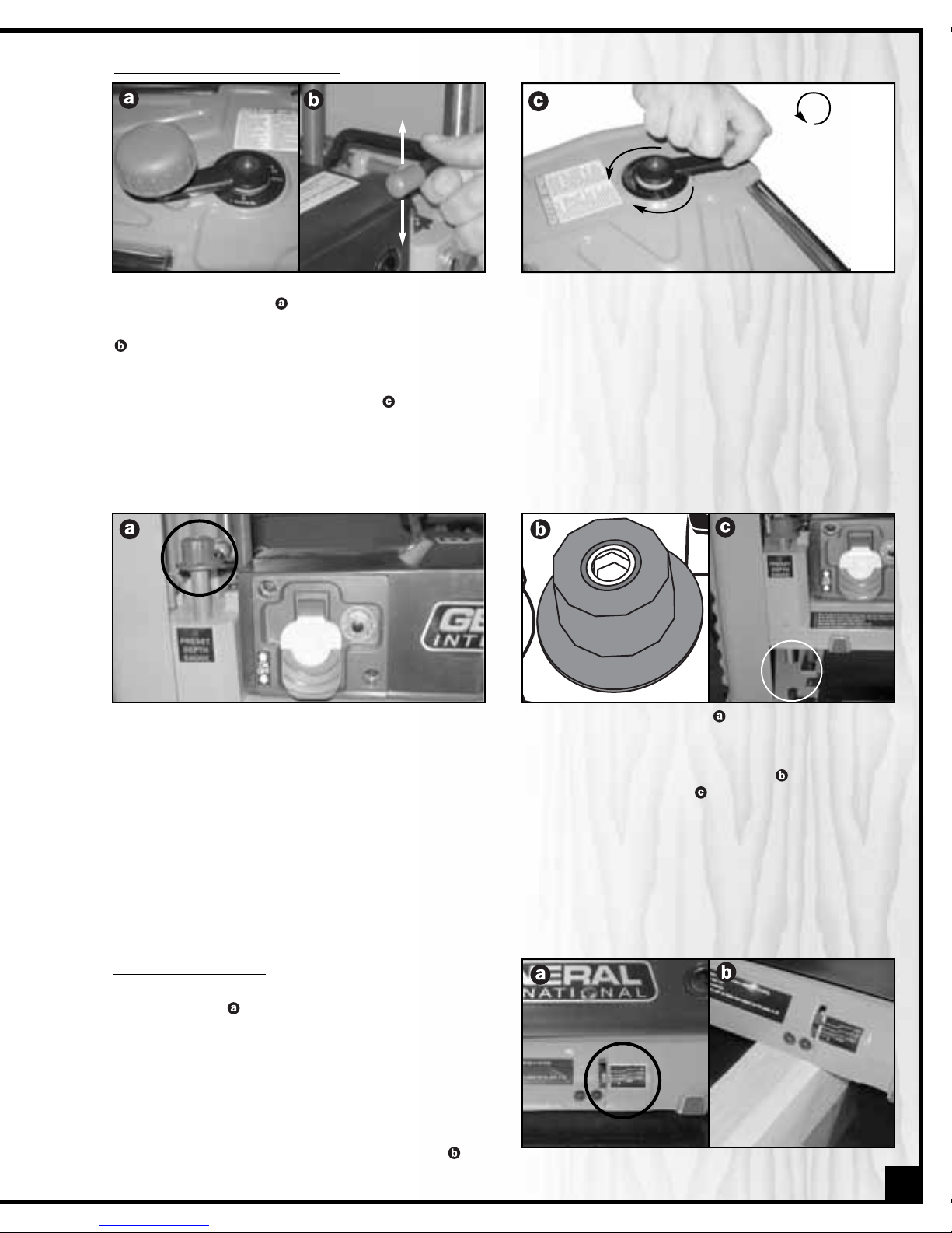
To adjust the depth of cut, the cutterhead assembly can be raised or lowered as needed by rotating the depth of
cut adjustment handle,
.
Before adjusting the height of the cutterhead, make sure the cutterhead locking lever is unlocked (raised position),
. Attempting to adjust the height of the cutterhead with the locking lever engaged will cause premature wear of
the locking mechanism.
NOTE: Each full clockwise rotation of the handle will lower the cutterhead by 1/16”. Each full counterclockwise rotation will raise the cutterhead by 1/16”
,.
RAISING/L
OWERING THE CUTTERHEAD
UNLOCK
LOCK
DOWN
UP
9
1 x = 1/16”
The adjustable pre-set depth gauge located on the top left of the cutterhead assembly,,allows the user to select
one of six commonly used workpiece final thickness settings.
With the cutterhead set slightly above the height of the workpiece press down and rotate the spring loaded adjustment knob to select the desired final thickness setting from either 1/8”, 3/8”, 1/2”, 3/4”, 1”& 1 1/4”, . This will set the
stop pin to prevent the cutterhead from going any lower than the selected thickness, .
NOTE: Once you have planed the workpiece down to the selected thickness, do not attempt to lower the cutterhead
further. Forcing the depth of cut handle when the cutterhead has bottomed out on the preset stop pin will damage
the raising mechanism.
1/8”
1 1/4”
1“
3/8”
1/2”
PRE-SE
T THICKNESS STOP GAUGE
DEPTH OF CUT INDICATOR
The depth of cut indicator on the lower right hand side of
the cutterhead,,will indicate how much material the
cutterhead is set to remove from the workpiece for a
given pass.
The pointer will read zero until the workpiece engages the
front of the cutterhead. Place the workpiece under the
front of the cutterhead and turn the height adjustment
handle clockwise until the cutterhead makes contact
with the workpiece & until the depth of cut indicator
shows the reading that matches the desired cut,
.

CHANGING FEED SPEEDS
The unit is equipped with a two feed speed transmission.
The feed speed adjustment knob is located on the left
hand side of the machine,
.
With the knob pushed all the way in the feed speed is set
for 18 feet per minute (FPM). With the knob pulled out to
the first stop the transmission will be in the neutral position
- stock will not feed. With the knob pulled out to its maximum the feed rate is set for 26 FPM,
.
Experiment with feed speeds based on the workpiece
material and its width as well as the depth of cut, to find
which setting work best for your needs. As a general
guideline however, for best results more aggressive cuts
or wider materials should be planed at slower speeds
and lighter cuts or narrow materials can be planed at
higher speeds.
TO AVOID DAMAGE TO THE GEARBOX, SPEED CHANGES SHOULD ONLY BE MADE WHILE THE MACHINE IS
RUNNING.
10
Failure to follow these recommendations will lead to premature blade wear and may cause premature motor
failure.
It is recommended that for both hard and soft wood:
For stock up to 5 1/2” in width never remove more that
1/8” per pass,
.
For stock of 5 1/2”-13” in width never remove more than
1/16” per pass,
.
Removing less material per pass and taking multiple
passes is always preferred to more aggressive planing.
Advantages include longer blade life, better finish quality (resulting in less time sanding later) and less likelihood of
removing too much material causing the workpiece to be too thin for its intended use.
OPERATING INSTRUCTIONS
BASIC PRINCIPLES OF PLANING
This thickness planer is designed to remove material from
the top face of a board in order to bring the board (or a
series of boards) down to a specific desired thickness.
To obtain even, uniform thickness across the length of a
board, the stock being planed must have one face that
has already been machined perfectly flat (usually on a
jointer) and the stock should be fed with this flat face
against the table,
.
If it is not possible to machine one face perfectly flat before planing, take shallow passes all on the same face of
the board until this face has been machined level. Then the board should be flipped over and the leveled face
should be fed face down against the table to allow you to dimension the board to final thickness.
1/8”
1/16”
1/32”
1/64”
0
1/8”
or less
1/16”
or less
1/8”
1/16”
1/32”
1/64”
0
1/8”
1/16”
1/32”
1/64”
0
1/8”
1/16”
1/32”
1/64”
0
5 1/2”
(or less)
5 1/2”- 13”
FLAT SIDE DOWN

This planer is not intended (and should not be used) to
plane any material other than solid wood.
The workpiece should always be fed through the planer
in the general direction of the grain in the wood,
.
Before being fed through the planer all lumber should be
inspected for debris and foreign objects such as staples
or nails. Foreign objects stuck to, or embedded in your
workpiece can be ejected from the machine at high
speed and cause serious injury or damage cutter knives.
Make sure to remove all such foreign objects from the
wood before running it through the planer.
Select lumber carefully and avoid workpieces with loose or protruding knots. Workpieces that are twisted, severely
deformed or warped should also be avoided. Warped, twisted, damaged or fragile stock runs an increased risk of
jamming in or damaging the machine or cutters. There is also a much greater risk of injury to the operator or
bystanders from kickback, where the workpiece is forcefully or violently ejected from the machine due to a jam,
whenever working with such damaged or warped wood.
THE MAXIMUM PLANING
WIDTH OF THIS UNIT IS 13”.
THE MAXIMUM WORKPIECE
THICKNESS OF THIS UNIT IS 6”
THE MINIMUM THICKNESS TO WHICH A WORKPIECE
CAN BE SAFELY PLANED WITH THIS
UNIT IS 1/8” .
THE MINIMUM WORKPIECE LENGTH THAT CAN BE
SAFELY PLANED WITH THIS UNIT IS 5”.
RESPECT THE RATED LIMITS OF THIS MACHINE IGNORING THESE LIMITS AND FEEDING NON COMPATIBLE STOCK INTO
THIS PLANER CAN LEAD TO SERIOUS INJURY TO THE USER OR SHOP BYSTANDERS, AND CAUSE DAMAGE TO THE WORKPIECE AND/OR THE MACHINE. IF THE STOCK YOU WISH TO PLANE DOES NOT MEET OR COMPLY WITH THE LIMITATIONS
LISTED ABOVE, FIND ANOTHER SAFER WAY TO PERFORM THE REQUIRED TASK.
11
CHECKLIST BEFORE STARTING
Make sure the workpiece has been inspected and is suitable for planing as explained in the previous section
“Basic Principles of Planing”.
If multiple boards are to be planed, collect all workpieces together and set them nearby on a table or bench
within easy reach. To limit the potential for injury in the
event of a kickback,avoid having to step or reach in front
of the machine to pick up the next workpiece, .
Make sure to have on safety glasses as well as hearing
and respiratory protection at all times when using the
planer.
Make sure you and any assistants are wearing safe appropriate workshop attire. Roll up long sleeves, secure long
hair and remove any jewelry: watches, rings, bracelets or anything that could become caught in the feed rollers or
other moving parts, potentially causing serious injury.
If working with longer workpieces, make sure to have adequate outfeed support safely set-up and ready before
planing.
AVOID HAVING TO STEP OR REACH IN
FRONT OF THE MACHINE.
GRAIN DIRECTION
GRAIN DIRECTION
Max. 13”
Min. 1/8”
Max. 6”
Min. 5”

1/8”
1 1/4”
1“
3/8”
1/2”
With the planer turned off position the workpiece on
the infeed table with the flat face down and the face
to be planed facing up.
RAISING/L
OWERING THE CUTTERHEAD
If a specific pre-set thickness is required, set the depth
stop to the desired final workpiece thickness.
Slide the workpiece up to the cutterhead and using
the depth of cut adjustment handle, raise or lower the
cutterhead as needed to obtain the desired depth of
cut.
Set the board aside, pull down on the cutterhead locking lever, , and turn on the planer, .
If necessary change the feed speed to select the desired feed rate: 18 or 26 FPM.
Stand to one side of the machine and set the board
back on the infeed table with the face to be planed
facing up.
TO LIMIT THE POTENTIAL FOR INJURY IN THE EVENT OF A
KICKBACK, AVOID STANDING DIRECTLY IN LINE WITH
THE FRONT OR BACK OF THE PLANER WHENEVER A
BOARD IS ENGAGED IN THE CUTTERHEAD.
12
LOCK
Align the board laterally so that it will be fed through
the planer in the general direction of the grain, and
allow the workpiece enough clearance to feed properly without rubbing or catching on either side of the
machine.
18FPM
26FPM
0

13
The return rollers on the top of the planer can be used
to pass the workpiece back to the front of the machine
for repeat passes.
Repeat these steps as needed for all boards that need
to be planed to the same thickness.
Step to the rear of the machine and recover the planed board on the outfeed table once it has cleared
the outfeed roller and has stopped advancing.
REPEA
T/MULTIPLE PASSES
In most cases several passes through the planer will be required to bring the workpiece(s) down to final thickness
dimension. In fact, it is generally preferable to remove less material per pass and achieve final thickness dimension
by taking multiple passes. This can extend blade life, place less strain on the motor and provide better workpiece
finish quality that will require less time spent sanding later.
Once all the boards have been passed through the planer once, set them aside and turn off the machine.
Inspect and measure the workpiece(s) thickness (not necessary if using the pre-set stop) and if more material
needs to be removed to reach the desired stock thickness, repeat the steps listed in the previous section “Planing”.
Take as many passes as needed to achieve final workpiece thickness, stopping the machine after each pass to
reset the cutterhead height.
NEVER PUSH, PULL OR OTHERWISE TRY TO MOVE OR REPOSITION THE WORKPIECE ONCE IT IS IN THE CONTROL
OF THE AUTOMATIC FEED ROLLERS.
Slowly slide the workpiece forward until the infeed roller “grips” the board. Release the board allowing the
feed roller to automatically feed the board through
the planer.

14
MAINTENANCE AND ADJUSTMENTS
PERIODIC MAINTENANCE
• Inspect/test the ON/OFF switch before each use. Do not operate the planer with a damaged switch; replace a
damaged switch immediately.
• Keep the machine as well as the in-feed out-feed tables clean and free of saw dust, woodchips, pitch or glue.
Vacuum or brush off any loose debris and wipe down the machine and the tables occasionally with a damp
rag.
• An occasional light coating of paste wax can help protect the tables’ surface and reduce workpiece friction.
Ask your local distributor for suggestions on aftermarket surface cleaners, protectant and dry lubricants based
on what is readily available in your area.
• Avoid using silicon based products that may affect wood finishing products such as oil, solvent or water-based
stains, varnishes and lacquers.
• Periodically inspect the power cord and plug for damage. To minimize the risk of electric shock or fire, never
operate the planer with a damaged power cord or plug. Replace a damaged power cord or plug at the first
visible signs of damage.
• The motor and cutterhead bearings are sealed and permanently lubricated – no further lubrication is required.
• The drive gears, chain and elevation screws should be cleaned of woodchips, dust, debris and old grease after
every 10-15 hours of use. After cleaning, re-apply a generous coating of any common automotive bearing
grease.
• Regularly inspect planed workpieces for signs of knife damage or wear and replace damaged or worn knives
immediately.
MAKE SURE THE PLANER HAS BEEN TURNED OFF AND UNPLUGGED FROM THE POWER SOURCE BEFORE PERFORMING
ANY MAINTENANCE.
There are 2 reversible cutterhead knives (blades) installed in the planer at the factory, . With usage and normal
wear over time, it will eventually become necessary to reverse and/or replace the knives.
When needed, replacement knives (sold in sets of 2), , can be ordered through your local General International
distributor under part #30-013.
Tip/Hint: To avoid potentially costly downtime, consider having a spare set of replacement knives on hand and
ready for use when needed.
Observing planed workpieces as they come out of the machine and looking for signs of knife damage or wear is
the best method to help you to determine when knives are due to be changed.
MAKE SURE THE PLANER HAS BEEN TURNED OFF AND UNPLUGGED FROM THE POWER SOURCE BEFORE PERFORMING
ANY MAINTENANCE.
INSPECTING/REPL
ACING CUTTERHEAD KNIVES
DOUBLE EDGE

1. A raised ridgeline in the workpiece that runs a straight line from beginning to end of the board , . This is ge-
nerally an indication that one or both of the knives has been nicked or damaged by a foreign object such as
a nail, staple or other hard object hidden or embedded in the workpiece.
2. A slight washboard or chatter effect, , which can be an indication of uneven knife wear causing one knife to
cut slightly deeper than the other.
3. Rough, irregular, torn or fuzzy grain on a freshly planed surface may be a sign of worn or dull blades
causing the wood to tear out. Sharp blades cut crisply and leave a relatively smooth finish.
Note: Fuzzy grain can also be a sign of high moisture content in the workpiece. If knives have recently been changed or if you suspect that moisture content and not dull knives is the cause, set the workpiece aside and test by
planing other boards with known or acceptable moisture content. If the planed results using a different workpiece
are smooth, then moisture content in your wood is the problem - no adjustments can be made to the machine for
this. Set the “wet” stock aside and simply work with drier wood.
15
Signs to look for include:
To maintain even knife wear always reverse or replace both knives each time knife reversal or replacement is
required.
T
o replace the knives:
1. Turn off and unplug the machine from the power source.
2. Using the t-handle allen wrench, remove the screws holding the chip deflector to the rear of the planer
and remove the chip deflector from the machine, .
3. Rotate the cutterhead towards you by hand until the spring-loaded stop latch engages and prevents the
cutterhead from turning. This will expose the knife retaining plate screws, .
4. Unscrew and set aside the 6 screws, .
5. Using the supplied magnets, , remove the knife retaining plate as shown, , and set it aside.
EFFECT EXAGGERATED
FOR CLARITY

16
NEVER RUN A FINGER OR OTHER BODY PART ALONG THE CUTTING EDGE OF THE KNIFE TO TEST FOR SHARPNESS
OR TO DETERMINE IF THE EDGE IS WORN OR HAS ALREADY BEEN USED. FAILURE TO HEED THIS WARNING CAN
LEAD TO SERIOUS INJURY.
CUTTERHEAD KNIVES HAVE SHARP EDGES AND CAN CAUSE DEEP CUTS TO FINGERS OR OTHER BODY PARTS. EXERCISE
EXTREME CAUTION WHEN HANDLING THE KNIVES. TO LIMIT THE POTENTIAL FOR INJURY, USE THE SUPPLIED MAGNETS
TO REMOVE, INSTALL OR OTHERWISE HANDLE CUTTERHEAD KNIVES.
Tip/Hint: To disengage the magnets from the knives after removal or installation, simply tilt the magnets slightly until
their “grip” on the metal surface is broken
,.
6. Using the supplied magnets remove the knife from the cutterhead, . If the reverse edge of the knife
has not already been used, simply rotate the knife 180° and re-install it. If both edges of the knife have been
used, discard the old knife and replace with a new one.
Tip/Hint: For the next future blade change and to eliminate guesswork and avoid having to remember if a knife
edge has already been used, using a marker, simply make a line or an “X” next to the edge that has already been
used
,.
Once you have marked an edge as having already been used, you will know that it cannot be used again.
Tip/Hint: To disengage the magnets from the knives after removal or installation, simply tilt the magnets slightly until
their “grip” on the metal surface is broken
,.
7. Note the knife alignment pins in the cutterhead, . These alignment pins take the guesswork out of aligning
both knives to the same height in the cutterhead. Using the magnets, install the knife, making sure the pins
are properly seated inside the alignment slots in the knife. The knife will be automatically set to the correct
height with no further adjustment required.
8. Using the supplied magnets, re-install the knife retaining plate and all 6 six screws that hold it in place.
Tip/Hint: Tighten the screws just slightly beyond hand tight. Over tightening the screws will make them very difficult
to remove for the next blade change.
9. Release the spring-loaded stop latch and rotate the cutterhead to expose the second knife retaining plate.
10. To reverse or replace the second knife, repeat steps 4-8.
11. After the second knife has been replaced and the knife retaining plate re-installed, re-install the chip
deflector.

REPL
ACING THE V-BELT
With use over time, the v-belt can wear and may eventually need to be replaced.
To replace a worn v-belt:
1. Turn off and unplug the machine from the power source.
2. To access the belt, unfasten the screws holding the right side panel in place and remove the side panel, .
3. Slip the belt off the pulleys by carefully pulling on the belt by hand while pulling outwards (away from the
pulley) to gradually rotate the belt off of the pulley, .
4. Install a new belt using the same technique taking care to ensure the the belt is properly seated in the grooves
of both pulleys.
5. Re-install the side panel and tighten down the screws.
17
DRIVE CHAIN/GEAR LUBRICA
TION
Periodically the drive chain and gears will need to be cleaned and greased to help maintain smooth feeding and
contribute to longer machine life and trouble free operation.
To clean and grease the drive chain and gears:
1. Turn off and unplug the machine from the power source.
2. To access the chain and gears, unfasten the screws holding the left side panel in place and remove the side
panel, .
3. Remove old grease and dust deposits by wiping with a dry rag.
4. Apply generous dabs of any common automotive bearing grease to the gears and chain, .
5. Re-install the side panel and tighten down the screws.

Replacement Knife Set
(2 kniv
es per set)
#30-013
13” steel replacement
knives. Double edged
(reversible design) for
longer service life.
Alignment slots for autoaligning; takes the guesswork out of setting knife
height for quick easy knife
changes.
Heavy Duty Open Based
Steel Stand
#30-015
Easy to assemble, wide
based stable design with
mounting slots for permanent planer installation.
Foot print measures 33”
(833) x 24 1/2”. Floor to top
of stand height: 28”
(711mm).
Dust Hood
#30-020
Connects to the chip
deflector at the rear of the
planer includes 4” dia
outlet to connect standard
dust hose for efficient
dust/chip collection (dust
hose and dust collection
systems sold separately).
Roller Stands
#50-150, 50-170 & 50-167S
For added in-feed or
out-feed support when
planing longer stock. Ask
your General International
distributor about our wide
selection of heavy duty
roller stands.
Dust Collector
s
We offer a wide selection
of top quality dust collectors to suit all your shop
needs. Dust collectors
contribute to a cleaner
more healthful workshop
environment.
RECOMMENDED OPTIONAL ACCESSORIES
FOR YOUR PLANER
We offer a large variety of products to
help you increase convenience, productivity, accuracy and safety when using
your planer. Here’s a small sampling of
optional accessories available from your
local General International dealer.
For a complete list of products, please visit
our website at www.general.ca
18
31
137
138
15
44
105
115
121
119
120
138
118
117
107
106
113
114
43
42
103
103
102
104
60
110
101
76
108
4
78
2
1
124
99
101
100
135
25
29
77
125
7
135
3
4
6
64
122
97
47
96
90
85
89
144
17
48
49
47
126
46
15
139
43
40
39
123
45
16
51
47
49
50
19
18
20
22
23
21
13
14
16
57
60
55
54
52
56
63
111
141
53
61
142
76
30
98
24
47
28
28
47
21
47
30
65
29
140
27
26
68
70
69
36
38
71
35
71
33
82
5
32
83
37
38
34
21
72
12
6
7
87
91
92
93
94
95
109
88
86
47
80
75
74
79
41
73
127
136
56
54
57
58
58
59
59
62
16
81
84
66
47
143
8
9
10
11
19
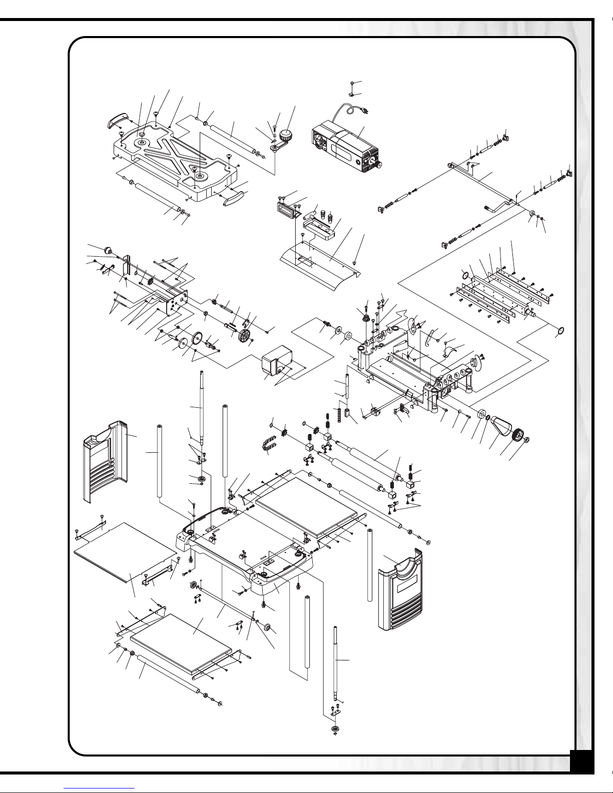
PLANER

20
PARTS LIST
30-010
PART N0. REF. N0. DESCRIPTION SPECIFICATION QTY
30010-01 170387-000 UPPER COVER 1
30010-02 340008-615 BUSHING 1
30010-03 000802-101 ROUND HEAD SCREW M8 X 1.25P X 16 4
30010-04 001102-503 SELF TAPPING SCREW M4 X 1.59P X 10 12
30010-05 130121-000 BUSHING 1
30010-06 250087-615 BUSHING 4
30010-07 190021-906 RETURN ROLLER 2
30010-08 280049-905 POINTER 1
30010-09 006001-035 FLAT WASHER 6.7 X 19 X 1.0 1
30010-10 000801-104 ROUND HEAD SCREW M6 X 1.0P X 20 1
30010-11 920124-000 HANDLE ASSEMBLY 1
30010-12 250098-615 LIFTING HANDLE 2
30010-13* PH05-01 MOTOR ASSEMBLY
30010-14 021102-000 CORD CLAMP ACC-2.5 1
30010-15 001901-101 SET SCREW M5 X 0.8P X 5 3
30010-16 001601-101 PHILLIPS HEAD SCREW W/WASHER M4 X 0.7P X 8/4 X 10 X 0.8t 7
30010-17 920125-000 DUST CHUTE 1
30010-18 170390-904 CHIP DEFLECTOR 1
30010-19 000801-102 ROUND HEAD SCREW M6 X 1.0P X 12 2
30010-20 220031-000 CUTTERHEAD 1
30010-21 360338-000 KNIFE POSITIONING PIN 8
30010-22 210122-000 KNIFE 2
30010-23 170280-904 KNIFE RETAINING PLATE 2
30010-24 250650-000 SIDE PANEL - RIGHT 1
30010-25 250676-000 SIDE PANEL - LEFT 1
30010-26 002402-101 PHILLIPS HEAD SCREW W/WASHER M5 X 0.8P X 12/5 X 10.5 X 1.0t 1
30010-27 280082-000 SPRING 1
30010-28 000102-313 CAP HEAD SCREW M5 X 0.8P X 75 4
30010-29 010006-000 "S" RING STW-15 3
30010-30 380257-901 CHAIN SPROCKET 3
30010-31 250372-615 KNOB 1
30010-32 012002-008 KEY 4 X 4 X 40 1
30010-33 360571-000 SHAFT 1
30010-34 170773-902 GEAR BOX COVER 1
30010-35 160037-000 BUSHING 1
30010-36 320236-000 GEAR 1
30010-37 320238-000 DOUBLE GEAR 1
30010-38 160019-000 BRONZE BUSHING 3
30010-39 000103-103 CAP SCREW M6 X 1.0P X 12 1
30010-40 250143-616 PRE-SET STOP DIAL 1
30010-41 030403-000 BEARING 6202-2NK 1
30010-42 000102-102 CAP SCREW M5 X 0.8P X 8 4
30010-43 170292-901 RETENTION PLATE 4
30010-44 000103-102 CAP SCREW M6 X 1.0P X 10 4
30010-45 250144-615 CORD STORAGE BRACKET 2
30010-46 280038-901 SPRING 1
30010-47 000303-103 PHILLIPS HEAD SCREW M5 X 0.8P X 10 20
30010-48 170316-905 RATCHET PLATE 1
30010-49 001602-101 PHILLIPS HEAD SCREW W/WASHER M5 X 0.8P X 10/5 X 12 X 0.8t 2
30010-50 170396-901 BELT COVER 1
30010-51 090057-000 UPPER FRAME 1
30010-52 920126-000 LOCK LEVER ASSY 1
30010-53 010105-000 "D" RING RTW-40 1
30010-54 360340-902 ROD 4
30010-55 012003-002 KEY 5 X 5 X 10 1
30010-56 280046-901 SPRING 4
PLANER

21
PARTS LIST
30-010
PART N0. REF. N0. DESCRIPTION SPECIFICATION QTY
30010-57 130030-000 PAD 4
30010-58 008004-100 HEX NUT M5 X 0.8P 4
30010-59 000001-104 HEX BOLT M5 X 0.8P X 16 4
30010-60 010205-000 "E" CIRCLIP ETW-8 4
30010-61 010103-000 "D" CIRCLIP RTW-35 1
30010-62 011001-104 SPRING PIN 3 X 12 1
30010-63 130032-000 CAM 1
30010-64 008006-100 NUT M8 X 1.25P-13 1
30010-65 290029-902 SHOULDER BOLT 1
30010-66 920261-000 IDLER ASSEMBLY 1
30010-68 160034-000 BUSHING 2
30010-69 320239-000 GEAR 1
30010-70 320235-000 GEAR SHAFT 1
30010-71 012002-002 KEY 4 X 4 X 7 2
30010-72 090104-000 GEAR BOX 1
30010-73 320229-000 GEAR 1
30010-74 360345-902 DEPTH ROD 1
30010-75 011001-103 SPRING PIN 3 X 10 1
30010-76 008005-100 HEX NUT M6 X 1.0P 5
30010-77 000002-102 HEX BOLT M6 X 1.0P X 15 1
30010-78 016205-000 CHAIN #410 X 32P 1
30010-79 110016-000 BRACKET 1
30010-80 280048-000 SPRING 1
30010-81 920129-000 POINTER ASSEMBLY 1
30010-82 360048-901 SHAFT 1
30010-83 130099-000 CLUTCH 1
30010-84 200019-615 SPACER 1
30010-85 280036-901 SPRING 2
30010-86 250141-620 POINTER 1
30010-87 006303-100 LOCK WASHER 6.1 X 12.3 1
30010-88 000103-108 CAP SCREW M6 X 1.0P X 25 1
30010-89 280035-901 BRACKET SPRING 2
30010-90 130067-000 ROLLER BRACKET 4
30010-91 030404-000 BEARING 6203-2NK 1
30010-92 160020-000 SPACER 1
30010-93 014302-000 V-BELT 135J-6 1
30010-94 110009-000 CUTTERHEAD PULLEY 1
30010-95 008016-200 HEX NUT M16 X 1.5P 1
30010-96 170298-901 BRACKET PLATE 4
30010-97 340030-000 RUBBER ROLLER 2
30010-98 280037-000 BRACKET SPRING 2
30010-99 360307-000 COLUMN 4
30010-100 360343-902 LEFT SCREW 1
30010-101 012002-003 KEY 4 X 4 X 8 4
30010-102 270005-000 RETENTION PLATE 2
30010-103 320183-629 BEVEL GEAR 4
30010-104 010001-000 "C" CIRCLIP STW-10 2
30010-105 170392-000 MAIN TABLE 1
30010-106 000304-102 PHILLIPS HEAD SCREW M6 X 1.0P X 10 4
30010-107 170393-901 GUIDE PLATE 2
30010-108 270014-901 SPRING PLATE 4
30010-109 230238-905 SELF TAPPING SCREW/LOCK WASHER 1
30010-110 360344-902 DRIVE SHAFT 1
30010-111 090061-000 BASE 1
30010-113 000002-111 HEX HEAD BOLT M6 X 1.0P X 20 4
PLANER

PARTS LIST
30-010
PART N0. REF. N0. DESCRIPTION SPECIFICATION QTY
30010-114 011004-103 SPRING PIN 6 X 25 4
30010-115 000302-102 PHILLIPS HEAD SCREW M4 X 0.7P X 8 12
30010-117 170394-906 TABLE EXTENSION 2
30010-118 006001-026 FLAT WASHER 6.4 X 20 X 3.0t 4
30010-119 000103-101 HEX HEAD SCREW M6 X 1.0P X 8 4
30010-120 250084-615 BUSHING 4
30010-121 190022-906 TABLE EXTENSION ROLLER 2
30010-122 360342-902 RIGHT SCREW 1
30010-123 200014-615 TOOL TRAY 1
30010-124 230119-000 "T" HANDLE ALLEN WRENCH 1
30010-125 920130-000 KNIFE SETTING MAGNET 2
30010-126 006502-100 SPROCKET WASHER 5.3 X 10(BW-5) 1
30010-127 002603-101 CAP SCREW M5 X 0.8P X 10 1
30010-135 360305-901 SPRING PIN 4
30010-136 320237-000 GEAR 1
30010-137 001501-101 CAP SCREW W/LOCK WASHER
M8 X 1.25P X 20/8.2 X 15.4/8.5 X 19 X 2t
4
30010-138 170391-906 BRACKET 4
30010-139 000303-102 PHILLIPS HEAD SCREW M5 X 0.8P X 8 4
30010-140 160038-000 BUSHING 1
30010-141 006305-100 LOCK WASHER 8.2 X 15.4 1
30010-142 001102-502 SELF TAPPING SCREW M4 X 1.59P X 8 4
30010-143 170672-902 TRANSMISSION SHAFT GUIDE PLATE 1
30010-144 230215-901 SCREW 12
PLANER
22
NOTES

23
22
15
17
18
16
1
7
10
9
8
12
11
14
13
3
5
4
6
2
19
20
21
PARTS LIST
30-010
PART N0. REF. N0. DESCRIPTION SPECIFICATION QTY
30010-01A 920137-000 TEMPERATURE CONTROL SWITCH 18AMP 1
30010-02A 000303-103 PHILLIPS HEAD SCREW M5 X 0.8P X 10 2
30010-03A 250151-615 MOTOR HOUSING (LEFT) 1
30010-04A 020005-000 STRAIN RELIEF SB8R-3 1
30010-05A 230113-905 SELF TAPPING SCREW 4
30010-06A 090064-000 MOTOR COVER 1
30010-07A 030401-000 BEARING 6200-2NK 1
30010-08A 800011-000 ROTOR ASSEMBLY 110-120V 1
30010-09A 230103-905 SELF TAPPING SCREW 2
30010-10A 030402-000 BEARING 6201-2NK 1
30010-11A 250152-615 BRACKET 1
30010-12A 410007-000 STATOR ASSEMBLY 120V 1
30010-13A 920235-000 MOTOR HOUSING (RIGHT) 1
30010-14A 430003-000 BRUSH BRACKET 2
30010-15A 430012-000 MOTOR BRUSH 120V 2
30010-16A 430006-000 BRUSH COVER 2
30010-17A 230106-000 SELF TAPPING SCREW 2
30010-18A 380047-901 MOTOR PULLEY 1
30010-19A 250153-616 SWITCH MOUNTING PLATE 1
30010-20A 001201-501 SELF TAPPING SCREW M4 X 1.59P X 12 2
30010-21A 937152-000 SWITCH ASSEMBLY 1
30010-22A 453013-006 POWER CORD 14AWG X 3C X 2.8m 1
MOTOR
MOTOR

IMPORTANT: When ordering replacement parts, always give the model number, serial number of
the machine and part number. Also a brief description of each item and quantity
desired.
8360, Champ-d’Eau, Montreal (Quebec)
Canada H1P 1Y3
Tel.: (514) 326-1161
Fax : (514) 326-5565
Parts & Service
Fax : (514) 326-5555 Order Desk
orderdesk@general.ca
www.general.ca
30-010
 Loading...