


FEATURES
SPECIFICATIONS
• Sealed, permanently lubricated bearings.
• Cast-iron wheel guards and dust vents.
• One-piece quick adjusting spark guards.
• Large quick adjust eye shields.
• Easy-adjust cast tool rest.
• Safety key switch.
• Fine and coarse vitrified grinding wheels included.
• Rubber foot mounts reduce vibration and prevent sliding.
• Wheel dresser included.
MODEL MODEL
15-870 M1 15-910 M1
WHEEL SIZE 8” x 1” (203 x 25 mm) 10” x 1” (254 x 25 mm)
ARBOR SPEED 3450 RPM 1720 RPM
5
⁄
ARBOR SIZE
AMPERES 9.6 AMP 13.5 AMP
MOTOR 1 HP, 110 V, 1 Ph 1
WEIGHT 59 LBS (27 kg) 103 LBS (47 kg)
8
” (16 mm) 1” (25 mm)
1
⁄
2
HP, 110 V, 1 Ph

SAFETY RULES
READ CAREFULLY BEFORE OPERATING THE M ACHINE
. Make sure that the operator has been properly
1
trained and has read, and understands, the owners
manual before operating any machinery.
2. Learn the machine’s applications and it’s limita-
tions (what it can and cannot do), as well as the
potential dangers that are particular to the unit.
Carefully follow all operating instructions and safety guidelines.
3. Keep the work area clean and well lit.
4. Do not wear loose-fitting clothing or jewelry that
may become caught in the machine or it’s components, as this can lead to serious injury, including
amputation. Always wear proper face, eye, ear,
respiratory and body protection, suitable to the
operation being performed.
5. Keep hands and other body parts well away from
grinding wheels and all moving parts, or other
cutting tools. Do not clear chips and grinding dust
away with hands, use a brush.
6. Make sure the grinding wheels are running at full
operating speed before grinding.
7. Do not force the grinding wheels or push too hard.
The unit will perform better, safer and more effectively at the speed or rate for which it was designed.
8. Whenever possible use a dust collector to minimize
health hazards.
2. Never stand or lean on the bench grinder. Serious
1
injury could occur if the unit is tipped or if unintentional contact is made with its’ moving parts.
13. Before starting the unit make sure the grinding
wheels are securely installed and tight to the arbor
shaft.
14. Keep all guards and safety devices in place and in
good working order. If a guard must be removed
for maintenance or cleaning make sure it is properly re-installed before using the machine again.
15. Before performing any maintenance, repairs or ad-
justments including wheel changes, make sure the
power is off and the unit is unplugged.
16. Before plugging in and turning on the power, make
sure that any adjustment tools, keys or wrenches
have been removed and safely stored.
17. Always, make sure that switch is in "OFF" position
before plugging in the power cord.
18. Only use accessories that are made or designed
for this machine. The use of parts or accessories that
are not recommended by General International
will void any warranty claims and may result in injury.
19. Make sure the machine is properly grounded. This
unit is supplied with a three-prong electric plug, it
should be plugged into a three-pole electrical
receptacle. Never remove the third prong.
9. Never leave the power on or the machine running
while it is unattended.
10. Keep children away. Make sure that visitors are
kept at a safe distance from the work area.
11. Use recommended speed grinding wheels, acces-
sories, and work piece material.
20. Do not use this bench grinder for any purpose other
than it’s intended use. If used for other purposes,
General International disclaims any real or implied
warranty and holds itself harmless for any injury
which may result from such use.
GENERAL ® INTERN ATIONAL Warranty
All component parts of GENERAL® International machinery are carefully inspected during all stages of production and each unit is
thoroughly inspected upon completion of assembly. Because of our commitment to quality, GENERAL® International agrees to repair or
replace any part or parts which, upon examination, proves to be defective in either workmanship or material for a period of 24 months from
date of purchase. To obtain warranty, all defective parts must be returned prepaid to GENERAL® International. Repairs made without the
written consent of GENERAL® International will void all warranty.
This warranty does not apply to items that would normally be consumed or require replacement due to normal wear such as: blades, grinding wheels, lubricants, belts, electric motors and electric components.

HEAVY DUTY BENCH GRINDER
15-870 / 15-910
Thank you for choosing this GENERAL® INTERNATIONAL heavy duty bench grinder.
This unit has been carefully tested and inspected before shipment and if properly
used and maintained, will provide you with years of reliable service. To ensure
optimum performance and trouble free operation a reasonable amount of care and
attention is required.To get the most from your heavy duty bench grinder,please take
the time to read this manual before assembling,installing and operating the unit.
UNPACKING AND CLEANUP
To ensure maximum performance from your GENERAL ® INTERNATIONAL heavy duty bench grinder, clean and
assemble it carefully before use. As soon as you receive the grinder, we recommend you follow these procedures:
1. Removing all the contents from the box and compare them with the contents list.
2. Report damage or missing items if any, to your local distributor immediately.
3. Clean all rust protected surfaces with a mild solvent or kerosene. Do not use lacquer thinner; paint thinner, or
gasoline as these will damage painted surfaces.
4. To prevent rust, apply a light coating of paste wax to surface.
WARNING!
NEVER CONNECT THIS UNIT TO AN OUTLET WITH A
GREATER VOLTAGE THAN REQUIRED!
TO AVOID ELECTRIC SHOCK TO THE OPERATOR ALWAYS
VERIFY THAT THE MACHINE IS PROPERLY GROUNDED!
ATTENTION!
ELECTRICAL REQUIREMENTS
Before connecting the machine to the power source verify that the voltage supplied corresponds to the required
voltage as specified on I.D. nameplate of the machine. A power source with greater voltage than needed can result
in serious injury to the user as well as damage the machine. If in doubt, contact a qualified electrician before connecting to the power source.
Never attempt to modify or repair the plug provided if it does not correspond with your outlet, contact a qualified
electrician to properly install the proper outlet.
ELECTRICAL GROUNDING
In the event of a malfunction or breakdown, grounding provides a path of least resistance for electric current to
reduce the risk of electric shock to the user. This bench grinder is equipped with an electric cord having an equipment grounding conductor and 3-prong grounding plug. Connect the plug to a matching outlet that is properly
installed and grounded in accordance with all local codes and ordinances.
Never modify the plug, if it does not correspond with your outlet, contact a qualified electrician in order to
install the proper outlet.
Never connect the grounding-conductor to a live terminal, this can result in electric shock to the operator!
The bench grinder is intended for use on a circuit that has an outlet that looks like the one illustrated in Fig.1, A temporary adapter, which looks like Fig.2, 3 may be used to connect this plug into a 2-pole receptacle as in Fig.2.
Note: In Canada, the use of a temporary adaptor is not permitted by the Canadian Electrical Code.
The temporary adapter should only be used until a qualified electrician can install a properly grounded outlet.
3

ROUNDING METHODS
P
U
L
L
O
U
T
T
O
L
O
C
K
P
U
L
L
O
U
T
T
O
L
O
C
K
G
Fig. 1 Fig. 2 Fig. 3
The use of an extension cord is not recommended, if necessary use a three-prong extension cord and outlet, if the extension will be used outside the cord must be suitable for outdoor use (immediately replace the extension cord if worn out,
cut or damaged). If in doubt contact a qualified electrician.
CAUTION!
PROLONGED GRINDING WILL CAUSE MOST MATERIALS
TO HEAT UP AND MAY BURN. USE CARE WHEN
HANDLING MATERIAL!
VERIFY THAT THE MOTOR VOLTAGE CORRESPONDS WITH
WARNING!
YOUR POWER SOURCE OUTLET!
OPERATING THE SAFETY SWITCH
Pull out the switch paddle to turn the grinder “ON”,and push it in to turn the grinder “OFF”. The paddle switch can
also be removed to prevent unauthorized use of the grinder. Make sure the switch is in the “OFF” position before
plugging in the bench grinder.
Fig. 4
INSTALLING THE TOOL REST ATTACHMENTS
• Unplug the grinder from the power source.
• Remove the tool rests from the top portion of the foam liner and
install them to the wheel guard as illustrated in Fig.4. Use the
knoband washers from the hardware bag to secure them in place.
Note: There is a left and a right tool rest, refer to Fig.4 to ensure that you
have installed them properly.
When grinding, the tool rests should be adjusted to within 1/8" of the
grinding wheel or other accessory being used.
INSTALLING SPARK GUARDS & EYE SHIELDS
Unplug the grinder from the power source. The spark guards and eye
shields are included in the hardware bag included with your grinder.
Fig. 5
The bag should contain
1 Eye shield mounting plate – right tilting 1 Eye shield mounting plate – left tilting
2 Spring washers 6 Flat washers
2 Crosshead screws W/Washers 1 Middle eye shield mounting plate – right
1 Middle eye shield mounting plate – left 2 Knobs
4 Hex bolts 4 Crosshead screws
2 Eye shields 2 Small eye shield mounting plate.
Carefully review Fig.4 and assemble one eye shield mounting rod, one
eye shield mounting plate, one eye shield, and two screws.
Follow the same procedure to assemble the second eye shield assembly.
Attach both eye shield assemblies to the wheel guards at opposite ends
of the bench grinder using the two hex bolts and the flat washers. (Fig. 5)
4

REPLACING GRINDING WHEELS
Follow these procedures to remove and replace the grinding
wheels.
1. Unplug the grinder from the power source.
2. Raise the eye shield out of the way.
3. Loosen and pull the tool rest out as far as possible. Do not
remove completely.
4. Remove the five screws from the side of the wheel cover, and
remove the wheel cover.
5. Insert a flat bladed screwdriver into the left-hand slot of the
grinding motor shaft. Hold the screwdriver firmly in order to
keep the shaft from turning as you loosen and remove the
hex nut in the center of the grinding wheel or other accessory.
NOTE: If you are changing only the right side accessory, you do not need to remove the left wheel cover. An
opening in the center of the cover permits the screwdriver to enter into the slotted shaft.
NOTE: The nut on the right side of the grinder has a standard right hand thread, turn counter-clockwise to loosen.
The left-hand nut has a left-hand thread, turn clockwise to loosen.
To release the nut in the center of the grinding wheel, it may be necessary to strike the wrench sharply in the
loosening direction with the heel of your hand.
Fig. 6
6. Remove the wheel washer and wheel.
7. Inspect the wheel for any cracks, chips, or any other damage other than normal wear. If damage is found do
not re-install or re-use the damaged wheel. Discard and replace a damaged wheel immediately. Verify the
blotters, if blotters are damaged replace with thin cardboard or blotter paper of the same shape.
Note: Never grind without blotters on each side of the wheel.
8. Install the new wheel, verify that both wheel washers are positioned correctly (Fig.6).
9. Hold wheel and tighten the nut firmly, do not over-tighten.
10. Re-install the wheel cover and the five screws.
11. Adjust the eye shields and tighten securely.
12. Re-adjust and tighten securely your tool rest to within 1/8" from the grinding wheel or other accessory.
OPERATION INSTRUCTIONS
1. In order to prevent movement of the grinder when pressure is applied against the wheel, mounting the grinder
on a flat stable surface such as a workbench is strongly recommended. If a bench is not available; Install and
bolt your bench grinder to a similar solid and stable work bench or stand .
2. Note the following features: The wheel on the left is a 60 grit (for model 15-870) or 46 grit (for model 15-910)
designed for medium material removal and general grinding.
3. The wheel on the right is a 36 grit (for model 15-870) or 24 grit (for model 15-910) designed for first or initial
material removal.
4. To operate the bench grinder, first put on safety glasses, then switch the "On" button. Allow the bench grinder to
achieve its full speed (1,720 RPM) before pressing a work piece against the grinding wheel.
5. Hold your work piece firmly against the tool rest, small work pieces must be held with pliers or other suitable
clamps.
6. Feed the work smoothly and evenly into the grinding wheel. Move the work piece slowly and try to avoid jam-
ming the work piece against the wheel. As the wheel tends to slow down you should occasionally release the
pressure to let the wheel return to full speed.
7. Grinding can only be done on the face of the grinding wheel, grinding should never be done on the side of
the grinding wheel unless you are equipped with a special wheel specifically made to side grind.
5

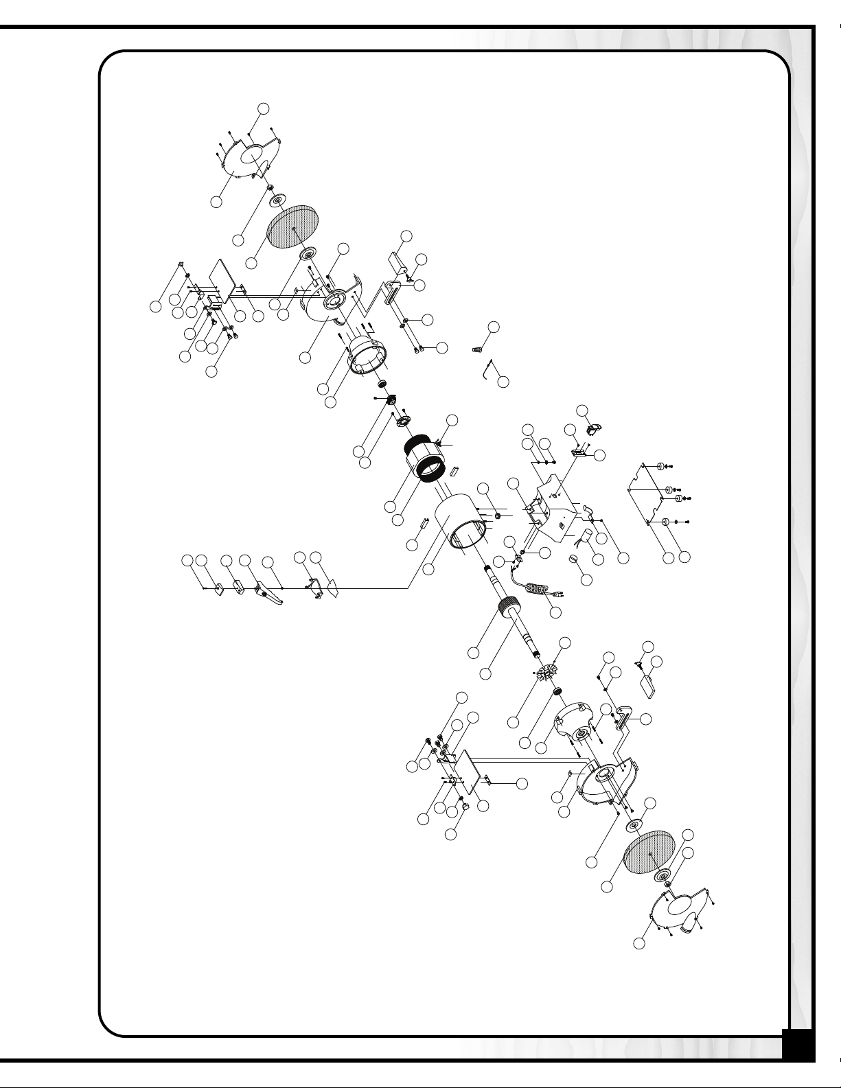
PARTS LIST
15-870
PART N0. DESCRIPTION SIZE QTY
15870-01 SHAFT 1
15870-02 ROTOR 1
15870-03 STATOR 1
15870-04 COPPER WIRE 1
15870-05 WIRE 4
15870-06 MOTOR HOUSING 1
15870-07 BASE 1
15870-08 STRAIN RELIEF BUSHING 1
15870-09 MOTOR FAN 1
15870-10 BEARING
15870-11 MOTOR COVER-LEFT 2
15870-12
CROSS HEAD SCREW W/WASHER 3/16" x 5/8"
15870-13 INNER WHEEL GUARD-LEFT 1
15870-14
CROSS HEAD SCREW W/WASHER 1/4" x 1/2"
15870-15 WHEEL FLANGE 4
15870-16 GRINDING WHEEL #60
15870-17 HEX. NUT
15870-18 OUTER WHEEL GUARD-LEFT 1
15870-19 CROSS HEAD SCREW
15870-20 INNER WHEEL GUARD-RIGHT 1
15870-21 GRINDING WHEEL #36
15870-22 HEX. NUT
15870-23 OUTER WHEEL GUARD-RIGHT 1
15870-24 STRAIN RELIEF BUSHING 1
15870-25 WIRE PLATE 1
15870-26 CENTRIFUGAL SWITCH 1
15870-27
CROSS HEAD SCREW W/WASHER 3/16” x 3/8”
15870-28 BUSHING 2
15870-29
CROSS HEAD SCREW W/WASHER 3/16" x 1/4"
15870-30 CAPACITOR
15870-31 BUSHING 1
15870-32 FIXTURE CLIP
15870-33
CROSS HEAD SCREW W/WASHER 3/16 x 1/4"
15870-34 POWER CORD W/PLUG 1
15870-35
CROSS HEAD SCREW W/WASHER 3/16" x 1/4"
#6204ZZ
8" x 1" x 5/8"
5/8” x 26”
1/4" x 1/2"
8" x 1" x 5/8"
5/8"
125V /200UF
34MM
2
8
6
1
1
10
1
1
2
2
1
1
1
1
PART N0. DESCRIPTION SIZE QTY
15870-36 COPPER WASHER
15870-37 TOOTH WASHER
15870-38 SWITCH 1
15870-39 SWITCH PLATE 1
15870-40
CROSS HEAD SCREW W/WASHER 3/16" x 1/4"
15870-41 PLATE 1
15870-42 PAD W/WASHER & SCREW 4
15870-43 TOOL REST-RIGHT 1
15870-44 TOOL REST SUPPORT-RIGHT 1
15870-45 KNOB
15870-46 FLAT WASHER
15870-47 HEX. SCREW
15870-48 TOOL REST-LEFT 1
15870-49 TOOL REST SUPPORT-LEFT 1
15870-50
15870-51
LARGE FIXED PLATE OF EYE SHIELD-SLOPE LEFT
LARGE FIXED PLATE OF EYE SHIELD-SLOPE RIGHT
15870-52 SPRING WASHER
15870-53 FLAT WASHER
15870-54
CROSS HEAD SCREW W/WASHER 1/4" x 1/2"
15870-55 HEX BOLT
15870-56 MIDDLE FIXED PLATE OF EYE SHIELD-LEFT 1
15870-57 MIDDLE FIXED PLATE OF EYE SHIELD-RIGHT 1
15870-58 KNOB
15870-59 CROSS HEAD SCREW
15870-60 EYE SHIELD 2
15870-61 SMALL FIXED PLATE OF EYE SHIELD 2
15870-62 WHEEL DRESSER COVER -UPPER 1
15870-63 DRESSING STONE 1
15870-64 DRESS KNOB 1
15870-65 CROSS HEAD SCREW
15870-66 HEX NUT
15870-67 DRESSER FIXED SUPPORT 1
15870-68 ADHESIVE TAPE 1
15870-69 LEAD WIRE 1
15870-70 TERMINAL 2
15870-71 LABEL 1
15870-72 SET SCREW
5MM
M5
5/16" x 1"
5/16" x 1"
5/16" x 3/4"
1/4"
1/4" x 13 x 1T
1/4" x 3/8"
1/4"
3/16" x 3/8"
3/16" x 1-1/4"
3/16"
3/16" x 1/4"
1
1
2
2
4
4
1
1
2
6
2
4
2
4
1
1
2
6
NOTES
18
17
16
14
6
60
13
61
56
54
53
59
58
52
49
12
48
47
46
45
41
42
4
30
33
31
5
32
39
10
11
9
53
50
55
1
34
2
4
24
6
28
8
7
35
37
3
27
26
19
T
T
40
38
36
69
5
70
44
20
11
12
61
60
15
45
43
14
21
22
58
55
59
57
52
51
53
53
54
23
71
71
72
68
67
66
64
63
62
65
15
15
46
47
29
25
R
O
T
A
T
I
O
N
R
O
T
A
T
I
O
N
15-870
7

PARTS LIST
15-910
PART N0. DESCRIPTION SIZE QTY
15910-01 SHAFT 1
15910-02 ROTOR 1
15910-03 STATOR 1
15910-04 COPPER WIRE 1
15910-05 WIRE 6
15910-06 MOTOR HOUSING 1
15910-07 BASE 1
15910-08 STRAIN RELIEF BUSHING 1
15910-09 MOTOR FAN 1
15910-10 BEARING
15910-11 MOTOR COVER 2
15910-12 CROSS HEAD SCREW
15910-13 SPRING WASHER
15910-14 INNER WHEEL GUARD-LEFT 1
15910-15 CROSS HEAD SCREW
15910-16 SPRING WASHER
15910-17 WHEEL FLANGE 4
15910-18 GRINDING WHEEL #46
15910-19 HEX. NUT
15910-20 OUTER WHEEL GUARD-LEFT 1
15910-21 CROSS HEAD SCREW
15910-22 INNER WHEEL GUARD-RIGHT 1
15910-23 GRINDING WHEEL #24
15910-24 HEX. NUT
15910-25 OUTER WHEEL GUARD-RIGHT 1
15910-26 STRAIN RELIEF BUSHING 1
15910-27 WIRE PLATE 1
15910-28 CENTRIFUGAL SWITCH 1
15910-29 CROSS HEAD SCREW W/WASHER
15910-30 BUSHING 2
15910-31 CROSS HEAD SCREW W/WASHER
15910-32 CAPACITOR BUSHING 1
15910-33 CAPACITOR
15910-34 FIXTURE CLIP 1
15910-35 CROSS HEAD SCREW W/WASHER
15910-36 POWER CORD W/PLUG 1
15910-37 CROSS HEAD SCREW W/WASHER
6206ZZ
1/4" x 7/8"
1/4"
5/16" x 3/4"
5/16"
10" x 1" x1"
1/4" x 1/2"
10" x 1" x1"
3/16" x 3/8"
3/16" x 1/4"
125V / 300UF
3/16" x 1/4"
3/16" x 1/4"
2
8
8
6
6
1
1"
1
10
1
1"
1
2
2
1
1
1
PART N0. DESCRIPTION SIZE QTY
15910-38 COPPER WASHER 1
15910-39 TOOTH WASHER
15910-40 SWITCH 1
15910-41 SWITCH PLATE 1
15910-42 CROSS HEAD SCREW W/WASHER
15910-43 PLATE 1
15910-44 PAD W/WASHER & SCREW 4
15910-45 CROSS HEAD SCREW W/WASHER
15910-46 TOOL REST-RIGHT 1
15910-47 TOOL REST SUPPORT-RIGHT 1
15910-48 KNOB
15910-49 FLAT WASHER
15910-50 HEX. SCREW
5/16" x 3/4"
15910-51 TOOL REST-LEFT 1
15910-52 TOOL REST SUPPORT-LEFT 1
15910-53
15910-54
LARGE FIXED PLATE OF EYE SHIELD-SLOPE LEFT
LARGE FIXED PLATE OF EYE SHIELD-SLOPE RIGHT
15910-55 SPRING WASHER
15910-56 FLAT WASHER
1/4" x 13 x 1T
15910-57 CROSS HEAD SCREW W/WASHER
15910-58 HEX BOLT
15910-59 MIDDLE FIXED PLATE OF EYE SHIELD-LEFT 1
15910-60 MIDDLE FIXED PLATE OF EYE SHIELD-RIGHT 1
15910-61 KNOB
15910-62 CROSS HEAD SCREW
3/16" x 3/8"
15910-63 EYE SHIELD 2
15910-64 SMALL FIXED PLATE OF EYE SHIELD 2
15910-65 WHEEL DRESSER COVER -UPPER 1
15910-66 DRESSING STONE 1
15910-67 DRESS KNOB 1
15910-68 CROSS HEAD SCREW
3/16" x 1-1/4"
15910-69 HEX NUT
15910-70 DRESSER FIXED SUPPORT 1
15910-71 ADHESIVE TAPE 1
15910-72 LEAD WIRE 1
15910-73 TERMINAL 2
15910-74 LABEL 1
15910-75 SET SCREW
3/16" x 1/4"
M5
3/16" x 1/4"
1/4" x 1/2"
1/4"
5/16"
1/4"
1/4" x 1/2"
1/4" x 3/8"
1/4"
3/16"
1
2
4
2
4
4
1
1
2
6
2
4
2
4
1
1
2
8
NOTES

20
19
18
15
63
14
64
59
57
56
62
61
55
52
12
51
50
49
48
43
44
4
33
35
32
5
34
41
10
11
9
56
53
58
1
36
2
4
31
26
27
6
30
8
7
37
39
3
29
28
21
P
T
T
42
40
38
72
5
73
47
22
11
12
64
63
17
48
46
15
23
24
61
58
62
60
55
54
56
56
57
25
75
R
O
T
A
T
I
O
N
74
R
O
T
A
T
I
O
N
74
13
16
16
21
17
17
45
49
50
56
13
17
68
65
66
67
69
70
71
15-910
9

15-870 / 15-910
8360, Champ-d’Eau, Montreal (Quebec)
Canada H1P 1Y3
Tel.: (514) 326-1161
Fax: (514) 326-5565
Fax: (514) 326-5555
orderdesk@general.ca
www.general.ca
Parts and Service
Order desk
IMPORTANT: When ordering replacement parts, always give the model number, serial number of
the machine and part number. Also a brief description of each item and quantity
desired.
 Loading...