


FEATURES
Simple design for easy set-up and maintenance.
Efficient collection and separation of large
chips which drop into the collector drum
before reaching the impeller.
High quality motor designed specifically
for heavy duty use and long service life.
Remote control for convenient operation
from virtually anywhere in the shop.
1-15 hours Pre-programmed timer run settings in 1 hour increments.
Equipped with an ultra efficient 1 micron
canister filter with total surface area of 48.4
square feet.
Canister filter equipped with crank handle/internal shaker for easy filter cleaning
without removing bag.
Sturdy steel support frame and collection
drum both equipped with casters for complete mobility within the shop.
30 gallon chip collection drum included.
SPECIFICA
TIONS
AIRFLOW CAPACITY
611 CFM
BLO
WER WHEEL DIAMETER
13”(330 MM)
SOUND RA
TING
80 DB
INLET DIAMETER
(1) 5”(127 MM)
OR (2) 4” (102 MM)
ST
ATIC PRESSURE
10”OF WATER
C
ANISTER FILTER (DIA X H)
15 3⁄4”X 19 3⁄4”(400 X 502 MM)
O
VERALL DIMENSIONS (L X W X H)
52 3⁄4”X 32”X 70”
(1340 X 810 X 1780 MM)
MO
TOR
1 1⁄2 HP, 110 V, 12 A
WEIGHT
198 LBS (90 kg)
SETUP & OPERATION MANUAL
REVISION 1 - JUNE 04/10
© Copyright General® International 06/2010
MODEL
10-800CF M1
PORTABLE 2 STAGE DUST COLLECTOR
– 1 1/2 HP

THANK YOU
for choosing this General®International model 10-800CF M1
1 1/2 HP Portable 2 Stage Dust Collector. This dust collector has been carefully tested and
inspected before shipment and if properly used and maintained, will provide you with year s
of reliable service. For your safety, as well as to ensure optimum performance and trouble-free
operation, and to get the most from your investment, please take the time to read this manual before assembling, ins talling and operating the unit.
The manual’s purpose is to familiarize you with the safe operation,basic function,and features
of this dust collector as well as the set-up,maintenance and identification of its parts and components. This manual is not intended as a substitute for formal woodworking instruction, nor to
offer the user instruction in the craft of woodworking. If you are not sure about the safety of
performing a certain operation or procedure, do not proceed until you can confirm, from
knowledgeable and qualified sources,that it is safe to do so.
Once you’ve read through these instructions, keep this manual handy for future reference.
Disclaimer:
The information and specifications in this
manual pertain to the unit as it was supplied from the
factory at the time of printing. Because we are committed to making constant improvements, General
®
International reserves the right to make changes to
components, parts or features of this unit as deemed
necessary,without prior notice and without obligation to
install any such changes on previously delivered units.
Reasonable care is taken at the factory to ensure that
the specifications and information in this manual corresponds with that of the unit with which it was supplied.
However, special orders and “after factory” modifications may render some or all information in this manual
inapplicable to your machine. Fur ther,as several generations of this model of dust collector and several versions of this manual may be in circulation,if you o wn an
earlier or later version of this unit, this manual may not
depict your machine exactly. If you have any doubts or
questions contact your retailer or our support line with
the model and serial number of your unit for clarification.
GENERAL® INTERNATIONAL
8360 Champ-d’Eau, Montreal (Quebec) Canada H1P 1Y3
Telephone (514) 326-1161 • Fax (514) 326-5555 • www.general.ca

GENERAL®& GENERAL®INTERNATIONAL WARRANTY
All component parts of General®, General® International and Excalibur by General
International ® products are carefully inspected during all stages of production and each unit
is thoroughly inspected upon completion of assembly.
Limited Lifetime
Warranty
Because of our commitment to quality and customer satisfaction, General® and General®
International agree to repair or replace any part or component which upon examination,
proves to be defective in either workmanship or material to the original purchaser for the life
of the tool.
However, the Limited Lifetime Warranty does not cover any product used for professional or commercial production purposes nor for industrial or educational applications.
Such cases are covered by our Standard 2-year Limited Warranty only. The Limited Lifetime
Warranty is also subject to the “Conditions and Exceptions” as listed below.
Standard 2-Year Limited Warranty
All products not covered by our lifetime warranty including products used in commercial,
industrial and educational applications are warranted f or a period of 2 years (24 months) from
the date of purchase. General® and General® Inter national agree to repair or replace any
part or component which upon examination, proves to be defective in either workmanship or
material to the original purchaser during this 2-year warranty period, subject to the “conditions
and exceptions”as listed below.
T
o file a Claim
To file a claim under our Standard 2-year Limited Warranty or under our Limited Lifetime
Warranty, all defective parts , components or machiner y must be returned freight or postage
prepaid to General® International, or to a nearby distributor, repair center or other location
designated by General® International. For further details call our service department at 1-888949-1161 or your local distributor for assistance when filing your claim.
Along with the return of the product being claimed for warranty, a copy of the original proof
of purchase and a “letter of claim”must be included (a warranty claim form can also be used
and can be obtained,upon request, from General® International or an authorized distributor)
clearly stating the model and serial number of the unit (if applicable) and including an explanation of the complaint or presumed defect in material or workmanship.
CONDITIONS AND EXCEPTIONS:
This coverage is extended to the original purchaser only. Prior warranty registration is not
required but documented proof of purchase i.e. a copy of original sales invoice or receipt
showing the date and location of the purchase as well as the purchase price paid, must be
provided at the time of claim.
Warranty does not include f ailures,breakage or defects deemed after inspection by General®
or General® International to have been directly or indirectly caused by or resulting from;
improper use, or lack of or improper maintenance, misuse or abuse, negligence, accidents ,
damage in handling or transport, or nor mal wear and tear of any generally considered consumable parts or components .
Repairs made without the written consent of General® Interna tionallwill void all warranty.

TABLE OF CONTENTS
Rules for safe operation . . . . . . . . . . . . . . .5
Additional safety instructions - specific to
this dust collector . . . . . . . . . . . . . . . . . . .
6
Electrical requirements . . . . . . . . . . . . . . .7
Grounding instructions . . . . . . . . . . . . . . . . . . . . . . .7
Circuit capacity . . . . . . . . . . . . . . . . . . . . . . . . . . . . .7
Extension cords . . . . . . . . . . . . . . . . . . . . . . . . . . . . .7
Identification of main parts and
components . . . . . . . . . . . . . . . . . . . . . . . . . . . . . . . . . . . .
8
Unpacking and preparation for set-up &
assembly . . . . . . . . . . . . . . . . . . . . . . . . . . . . . . . . . . . . . . . .
9
List of contents . . . . . . . . . . . . . . . . . . . . . . . . . . . . . .9
Additional requirements for set up . . . . . . . . . . . . .9
Shop placement / Space considerations . . .10
Layout out a plan for the piping . . . . . . . . . . . . .10
Assembly instructions . . . . . . . . . . . . .11-16
Operating Instructions . . . . . . . . . . . . .17-18
Connecting to a power source . . . . . . . . . . . . . . .17
Operating the control panel . . . . . . . . . . . . . . . . . .17
Circuit breaker . . . . . . . . . . . . . . . . . . . . . . . . . . . . .18
Operating the remote control . . . . . . . . . . . . . . . . .18
Seal air leaks (if needed) . . . . . . . . . . . . . . . . . . . .18
Before starting . . . . . . . . . . . . . . . . . . . . . . . . . . . . . .18
Maintenance & Servicing . . . . . . . . . . .19-20
Cleaning or replacing the canister filter . . . . . . . . . . . .19
Emptying the collector bag & drum . . . . . . . . . . .20
Recommended optional accessories . . . . .20
Parts list & diagrams . . . . . . . . . . . . . .21-23
Wiring diagram . . . . . . . . . . . . . . . . . . . .24

RULES FOR SAFE OPERATION
To help ensure safe operation, please take a moment to learn the machine’s applications and limitations, as well as potential hazards. General® International disclaims any real or implied warranty and holds itself harmless for any injury that
may result from improper use of its equipment.
1. Do not operate the dust collector when tired, distract
ed, or under the effects of drugs, alcohol or any medication that impairs reflexes or alertness.
2. The working area should be well lit, clean and free of
debris.
3. Keep children and visitors at a safe distance when the
dust collector is in operation; do not permit them to
operate the dust collector.
4. Childproof and tamper proof your shop and all
machinery with locks, master electrical switches and
switch keys, to prevent unauthorized or unsupervised
use.
5. Stay alert! Give your work your undivided attention.
Even a momentary distraction can lead to serious
injury.
6. Fine particulate dust is a carcinogen that can be hazardous to health. Work in a well-ventilated area and
wear face, eye, ear, respirator y and body protection
devices.
7. Do not wear loose clothing, gloves, bracelets, necklaces or other jewelry while the dust collector is in
operation. Wear protective hair covering to contain
long hair and wear non-slip footwear.
8. Do not insert hands, fingers or any foreign objects into
ventilation inlet and outlet openings.
9. Do not operate this machine without a canister filter
properly installed on the unit.
10. Clean filter on a regular basis and replace as needed.
11. Do not handle the electrical plug with wet hands.
12. Do not use this unit outdoors, on or near wet surfaces.
13. Always turn on the dust collector before starting the
dust producing machine. Always turn off the dust producing machine before turning off the dust collector.
14. Do not vacuum anything that is burning, smoking or
smoldering such as cigarettes, matches or hot ashes .
15. Do not vacuum or use this dust collector near flammable or combustible liquids, gases, gasoline or other
fuels, lighter fluid,cleaners, oil or solvent based paints,
natural gas, hydrogen or explosive dusts like coal
dust, magnesium dust, grain dust or gun powder.
16. Do not operate the unit until a dust hose is installed
onto the hose inlet.
17. Never leave the machine unattended while it is running or with the power on.
18. To avoid health hazards from vapors or dusts, do not
vacuum toxic material.
19. Use only recommended accessories. Use of accessories NOT recommended by GENERAL® INTERNATIONAL may result in a risk of injury or damage to the
machine.
20. Always disconnect the unit from the power source
before servicing, performing any maintenance or
repairs and when changing bags or hoses, or if the
machine will be left unattended.
21. Make sure that the switch is in the “OFF”position before
plugging in the power cord.
22. Make sure the tool is properly grounded. If equipped
with a 3-prong plug, it should be used with a threepole receptacle. Never remove the third prong.
23. Do not use this dust collector for any purpose other
than its intended use. If used for other purposes , GENERAL® INTERNATIONAL disclaims any real or implied
warranty and holds itself harmless for any injury, which
may result from that use.
5

Additional Safety Instr
uctions
Specific to this Dust Collector
Because each shop situation is unique, no list of safety guidelines can ever be
complete. The most important safety feature in any shop is the knowledge and good
judgement of the user. Use common sense and always keep safety considerations, as they apply
to your individual shop situation first and foremost in mind. If you have any doubts about the
safety of an operation you are about to perform: STOP! Do not perform the operation until
you have validated from qualified individuals if the operation is safe to perfor m and
what is the safest method to perform it.
7. Before connecting the machine to the power
source, verify that the voltage of your power supply corresponds with the voltage specified on the
motor I.D. nameplate. A power source with greater
voltage than needed can result in serious injury to
the user as well as damage to the machine. If in
doubt, contact a qualified electrician before connecting to the power source.
8.
The high speed blower fan inside the blower housing
can amputate fingers, grab loose clothes or neckties.
DO NOT insert fingers or any foreign object into the
blower housing.
9.
The sound level of this machine is rated at approximately 80 db during operation. Make sure that adequate hearing protection is used and that the overall
sound level within the work environment is taken
into consideration.
1. Make sure that the operator has been properly
trained and has read, and understands the owners manual before operating any machinery.
2. This dust collector is intended for indoor use for dry
dust collection only. To limit the risk of electrical
shock, do not use this unit outdoors or on or near
wet surfaces, and do not use this unit to collect or
vacuum liquids, nor wet or damp materials.
3. Always unplug the machine from the power
source before servicing, unclogging or cleaning
the unit.
4.
Fine particulate dust is a carcinogen that can be
hazardous to health. Work in a well-ventilated area
and wear face, eye, ear, respiratory and body protection devices.
5. Do not operate this dust collector with a damaged or malfunctioning switch; replace a damaged
or malfunctioning switch immediately.
6. Protect the power cord from damage. Be mindful
of the location of the power cord particularly when
moving the dust collector. Avoid crushing, rolling
over, s tepping on, cutting or in any way kinking or
damaging the cord or it’s plug.Avoid power cord
contact with oil, grease, hot surfaces or corrosive
chemicals or substances. Do not operate this dus t
collector with a damaged power cord or plug.
Replace a damaged power cord or plug at the
first signs of damage.
6

7
ELECTRICAL REQUIREMENTS
GROUNDING INSTRUCTIONS
In the event of an electrical malfunction or short circuit,
grounding reduces the risk of electric shock. The motor
of this machine is wired for 110V single phase operation
and is equipped with a 3-conductor cord and a 3prong grounding plug A to fit a grounded type receptacle B.Do not remove the 3rd prong (grounding pin) to
make it fit into an old 2-hole wall socket or extension
cord. If an adaptor plug is used C, it must be attached
to the metal screw of the receptacle.
Note: The use of an adaptor plug is illegal in some
areas. Check your local codes. If you have any doubts
or if the supplied plug does not correspond to your electrical outlet, consult a qualified eletrician before proceeding.
CIRCUIT CAPACITY
Make sure that the wires in your circuit are capable of
handling the amperage draw from your machine, as
well as any other machines that could be operating on
the same circuit. If you are unsure, consult a qualified
electrician. If the circuit breaker trips or the fuse blows
regularly, your machine may be operating on a circuit
that is close to its amperage draw capacity.However, if
an unusual amperage draw does not exist and a
power failure still occurs,contact a qualified technician
or our service depar tment.
BEFORE CONNECTING THE MACHINE TO THE POWER SOURCE,VERIFY THAT THE VOLTAGE OF YOUR POWER SUPPLY CORRESPONDS
WITH THE VOLTAGE SPECIFIED ON THE MOTOR I.D. NAMEPLATE. A POWER SOURCE WITH GREATER VOLTAGE THAN NEEDED CAN
RESULT IN SERIOUS INJURY TO THE USER AS WELL AS DAMAGE TO THE MACHINE. IF IN DOUBT, CONTACT A QUALIFIED ELECTRICIAN
BEFORE CONNECTING TO THE POWER SOURCE.
THIS TOOL IS FOR INDOOR USE ONLY. DO NOT EXPOSE TO RAIN OR USE IN WET OR DAMP LOCATIONS.
EXTENSION CORDS
If you find it necessary to use an extension cord with your
machine, use only 3-wire extension cords that have 3prong grounding plug and a matching 3-pole receptacle that accepts the tool’s plug. Repair or replace a
damaged extension cord or plug immediately.
Make sure the cord rating is suitable for the amperage
listed on the motor I.D. plate. An undersized cord will
cause a drop in line voltage resulting in loss of power
and overheating. The accompanying chart shows the
correct size extension cord to be used based on cord
length and motor I.D. plate amp rating. If in doubt, use
the next heavier gauge. The smaller the number, the
heavier the gauge.
A
B
C
TABLE - MINIMUM GAUGE FOR CORD
AMPERE
RATING
TOTAL LENGTH OF CORD IN FEET
110 VOLTS 25 FEET 50 FEET 100 FEET 150 FEET
220 VOLTS 50 FEET 100 FEET 200 FEET 300 FEET
AWG
< 5
------->
18 16 16 14
6 TO 10
------->
18 16 14 12
10 TO 12
------->
16 16 14 12
12 TO 16
------->
14 12 * NR * NR
* NR = Not Recommended

PORTABLE 2 STAGE DUST COLLECTOR – 1 1/2 HP
10-800CF M1
IDENTIFICATION OF MAIN PARTS AND COMPONENTS
8
N
B
C
D
E
H
F
G
I
L
J
K
O
P
Q
R
S
T
M
A
A- CONTROL PANEL
B- FAN HOUSING
C-
HOSE INLET
D- CYCLONE SEPARATOR
E- UPPER LEGS
F- UPPER CROSS BRACES
G- 7”FLEXIBLE HOSE
H- LOWER LEGS
I- CHIP COLLECTION DRUM ASS’Y
J- LEG CASTERS
K- COLLECTION DRUM CASTERS
L- LOWER CROSS BRACES
M- CANISTER FILTER HANGERS
N- MOTOR
O- 6”MAIN OUTLET
P- 6” FLEXIBLE HOSE
Q- CANISTER FILTER HANDLE
R- CANISTER FILTER
S- BAG CLAMP
T- COLLECTOR BAG

UNPACKING AND PREPARATION FOR SET-UP & ASSEMBLY
Use caution and wear gloves when handling metal
parts such as the belt clamps, which can cut if handled carelessly.
This model 10801CF M1 is very heavy. Do not overexert. The help of at least one assistant or a for klift
will be needed for the following steps. To limit the
risk of serious injury or damage to the machine, any
equipment used to lift this machine should have a
rated capacity in excess of 198 lbs - 90 kg.
UNPACKING
Carefully unpack and remove the unit and its components from its shipping container s and check for missing or
damaged items as per the list of contents below.
Note: Please report any damaged or missing items to your General® International distributor immediately.
M
Q
S
Y
R
V
J
N
K
U
l
h
U - PLASTIC COLLECTOR BAG..................................................................2
V - UPPER LEG ...........................................................................................4
W - 7” FLEXIBLE HOSE ...............................................................................1
X - REMOTE CONTROL..............................................................................1
Y - 6”FILTER OUTLET ..................................................................................1
Z - 12 MM HEX HEAD BOLT......................................................................1
a - 14 MM HEX HEAD BOLT......................................................................4
b - 12 MM FLAT WASHER..........................................................................1
c - 14 MM HEX LOCK NUT.......................................................................4
d - 14 MM HEX NUT ..................................................................................4
e - 14 MM LOCK WASHER........................................................................4
f - M4 METAL SCREW ...............................................................................3
g - 12-14 MM OPEN END WRENCH .........................................................1
h - CHIP COLLECTION DRUM ..................................................................1
i - LID LATCH ............................................................................................3
j - PHILLIPS HEAD SCREW (for drum latches) .......................................6
k - HEX NUT (for drum latches)..............................................................6
l - HANGER (LEFT AND RIGHT)................................................................2
m - BLOWER/FAN HOUSING .....................................................................1
n - AIR FLOW PIPE.....................................................................................1
o - CYCLONE SEPARATOR........................................................................1
LIST OF CONTENTS QTY
A - CANISTER FILTER.................................................................................1
B - Y-FITTING / INLET ................................................................................1
C - 6” OUTLET............................................................................................1
D - RUBBER SEAL ......................................................................................1
E - 3 X 6 MM FOAM GASKET ROLL ........................................................1
F - 10 MM FLAT WASHER.......................................................................82
G - 10 MM HEX NUT...............................................................................22
H - 10 MM HEX HEAD BOLT...................................................................64
I - CASTERS (LEGS).................................................................................4
J - CASTERS (DRUM) ...............................................................................4
K - 4” END CAP........................................................................................1
L - 6”HOSE CLAMP ................................................................................2
- 7” HOSE CLAMP.................................................................................2
M - LOWER LEG........................................................................................4
N - COLLECTOR DRUM LID......................................................................1
O - 10 MM FLAT WASHER ........................................................................4
P - 14 MM FLAT WASHER.......................................................................20
Q - LOWER CROSS BRACE.......................................................................3
R - UPPER CROSS BRACE.........................................................................4
S - 6” FLEXIBLE HOSE ...............................................................................1
T - CANISTER FILTER HANDLE....................................................................1
W
n
Z
A
a
b
c
d
e
f
D
F
G
H
L
T
X
ADDITIONAL REQUIREMENTS FOR SET UP
• 1 extra person for help with lifting
• Small & large Phillips Screwdriver
• 10 & 14 mm open end or socket wrenches
• Utility knife
or
g
E
I
9
i
j
m
o
k
O
P
C
B

10
SHOP PLACEMENT / SPACE CONSIDERATIONS
Because each shop situation is unique, the following factors should be taken into consideration when determining
and before deciding on the ideal installation to best suit your shop dust collection needs.
The unit should be installed as close to the dust source(s) as possible. This unit is mounted on caster s and as such
the dust collector can be moved from one location to another within the shop if a permanent installation location
is not practical or desired.
In all cases the unit should be installed on a flat, sturdy and stable surface that is able to suppor t the weight of the
unit (198 lbs - 90 kg) as well as the weight of the operator. The casters should be blocked to prevent the unit from
moving when it is in use.
This model 10-800CF M1
is equipped with a 5” main hose
inlet that is fitted with a dual-inlet “Y” fitting allowing you to
connect up to two 4”dust hoses .
Consider the space requirements for the unit and its use
when deciding where to install your dust collector in your
shop.
5”
32”
70”
4”
4”
52 3⁄4”
Wherever possible avoid running hoses and ducting along
the floor.
Keep hoses and ducting safely mounted along the walls.
LAYING OUT A PLAN FOR THE PIPING:
For permanent installations it is advisable to map out a rough layout of your planned installation starting from the
dust collector out to all the machines that you wish to connect to the system.You may vary your layout to suit your
specific shop needs and may choose to use metal or plastic ducting, or flexible hose in any combination as suited to your needs.
Note: To avoid accidents as well as damage to ducting or hoses, plan your installation with hoses and ducting running along walls or mounted from above wherever possible. See the accompanying examples of non-recommended and re-commended installations.
HOSES AND DUCTING RUNNING ALONG THE SHOP FLOOR BETWEEN MACHINERY CAN CAUSE USERS TO TRIP AND LEAD TO
SERIOUS INJURY.

ASSEMBLY INSTRUCTIONS
• SERIOUS PERSONAL INJURY COULD OCCUR IF YOU CONNECT THE MACHINE TO THE POWER SOURCE BEFORE YOU
HAVE COMPLETED THE SETUP PROCESS. DO NOT HOOK-UP THE MACHINE TO A POWER SOURCE UNTIL INSTRUCTED
TO DO SO.
• BE SURE TO READ AND UNDERSTAND THIS ENTIRE MANUAL.
• USE CAUTION AND WEAR GLOVES WHEN HANDLING METAL PARTS SUCH AS THE BELT CLAMPS, WHICH CAN CUT IF
HANDLED CARELESSLY.
• THE SOUND LEVEL OF THIS MACHINE IS RATED AT APPRO XIMA TELY 80 DB DURING OPERATION. MAKE SURE THAT ADEQUATE HEARING PROTECTION IS USED AND THAT THE OVERALL SOUND LEVEL WITHIN THE WORKING ENVIRONMENT
IS TAKEN INTO CONSIDERATION.
Har
dware/Tools Needed for the following steps*:
•
10 mm Hex Head Bolts
•
10 mm Flat Washers
•
10 mm Hex Nuts
•
10 mm open end or socket wrench
Tighten all bolts securely with a 10 mm open end or
socket wrench.
* Except where specified otherwise.
or
1. Carefully turn the fan/motor assembly upside
down.
2. Attach the air flow pipe to the fan housing using
4 bolts and 4 flat washers.
3. Remove the first inch (approx.) of backing strip A
from the start of the foam gasket B.
4. Gradually remove the rest of the backing as you
stick the foam gasket around the opening of the
cyclone separator A,as shown in B.Trim off excess
tape wih a knife or scissors, C.
A
B
A
B
C
11

5. Attach the cyclone separator to the fan housing
using 10 bolts and 10 flat washers as shown in A,
with the connection outlet B facing the side opposite to the mounting bracket C.
7. Attach the 4 upper cross braces on the inside of the
legs as shown in A, using 8 bolts, 8 hex nuts and 16
flat washers (1 bolt & washer on the outside B,and
1 washer and nut on the inside C).
B
C
A
A
6. Attach the 4 upper legs A to the fan housing as
shown in B, using 16 bolts and 16 flat washers (4
per legs, C).
B
C
A
8. Attach the 4 lower legs to the outside of the upper
legs as shown in A, sliding the lower legs over the
upper legs,B,then aligning the holes and securing
with 8 bolts, 8 hex nuts and 16 flat washers (1 bolt &
washer on the outside and 1 washer and nut on the
inside C).
C
B
A
B
C
9. Attach the 3 lower cross braces to the inside of the
lower legs (rear and both sides), using 6 bolts, 6
hex nuts and 12 washers.
Note: When attaching the cross braces, you may need to
manually adjust the distance between legs slightly,A,to
line-up the holes.
10.Attach the 4 casters to the lower legs as shown in A,
using 4 x 14 mm lock nuts and 8 x 14 mm flat washers B.
11.Tighten the nuts securely, holding the head of the
bolts C with the supplied thin 14 mm open end
wrench to keep it from turning while tightening the
lock nuts D using a regular 14 mm wrench.
A
C
A
D
12
B

13
12.Stick some foam gasket A around the opening of
the 6” Outlet as shown in B. Trim off excess gasket
with a knife or scissors, C.
B
13.Attach the 6”outlet to the right side of the fan hous
ing with 4 bolts and 4 flat washers.
15.Attach the L-type hangers to the mounting holes
on the right side of the fan housing as shown in A,
using 4 bolts and 4 flat washers,with the flat side of
the hangers facing each other, B.
16.Stick some foam gasket A around the opening of
Canister Filter B as shown in C. Trim off excess
gasket wih a knife or scissors.
17.Attach the filter outlet to the filter using 4 bolts and
4 flat washers.
A
A
C
HELP WITH LIFTING WILL BE NEEDED AT THIS
TIME. THE COLLECTOR BODY IS HEAVY - DO NOT
OVEREXERT.
14.With the help of an assistant, carefully turn the col-
lector body assembly right side up.
B
A
A
B
C

14
18.Attach the canister filter to the hangers, A, using
4 x 14 mm bolts and flat washers B. Tighten the
bolts securely.
A
19.Install one end of the 6” flexible hose A on the
filter outlet and the other end on the fan housing 6”
outlet A. Secure in place using the two 6” hose
clamps B.(If needed,refer to section in gray below .)
B
A
A
B
C
D
E
SECURING THE HOSE USING HOSE CLAMPS
20. Fit the handle on the shaft of the canister filter
and secure it in place using a 12 mm bolt and
washer B,as shown in A. Tighten with the supplied
12 mm wrench.
21.Fit a plastic collection bag over the bottom of the
canister filter and use the belt clamp to hold the
bag securely in place,making sure the metal strap
is sitting in the groove on the lower por tion of the
canister.
A
B
1. Loosen the clamp bolt as much
as possible A to loosen the hose
clamp, then unclamp it by
pushing in opposite directions as
shown in B.
2. Fit the opened clamp C around
the flexible hose.
3. Re-attach the clamp as shown
in D, then tighten bolt, E, using
a Phillips head screwdriver, to
tighten the clamp around the
hose.
USE CAUTION AND WEAR GLOVES WHEN HANDLING METAL PARTS SUCH AS THE BELT CLAMP,
WHICH CAN CUT IF HANDLED CARELESSLY.
B

22.Attach the casters A to the bottom of the chip collection drum B, using 4 x 14 mm hex nuts, 4 x 14
mm lock washers and 8 x 14 mm flat washers C.
23.Tighten the nuts securely, holding the head of the
bolts D with the supplied thin
14 mm open end
wrench to keep it from turning while tightening
the nuts F inside the drum, using a regular 14 mm
wrench.
A
C
B
D
F
1. Loosen and remove the nut on the metal belt,
then remove the metal belt.
2. Pull the upper dr um up and out of the lower drum.
2-PIECE COLLECTION DRUM
Note: The upper portion of the drum is stored inside the lower portion to save space for shipping. To remove the upper
drum from the lower drum:
24.Using a small Phillips screwdriver, attach the 3
drum latches A to the upper drum B as shown in C,
using the 6 supplied Phillips screws and hex nuts,C.
25.Install the upper drum on top of the lower drum
as shown in A and secure in place with the metal
belt B. Tighten the nut on the screw to firmly secure
the assembly, C.
B
A
C
OUTSIDE VIEW
INSIDE VIEW
A
B
C
15
D

28.Connect the chip collection drum to the funnel
port with the 7” flexible hose as shown, A.
29.Secure in place using the two 7”hose clamps B. (If
needed,refer back to the gray section on page 14.)
A
30.Attach the other end of the grounding wire to the
stand as shown in A (between the flat washer
and nut, as shown in B.)
A
B
31.Attach the dual-inlet “Y”fitting to the inlet as show in
A using 3 x M4 metal screws, B.
B
B
A
26.Install the rubber seal A over the top lip of the drum
rim as shown in B. Trim off excess seal wih a knife
or scissors
B
A
16
27.Secure the drum lid by clamping the 3 lid latches,
up as shown (see A and B).
Note: If needed, loosen the handle along the threaded
shaft so that the handle can reach the hook of the
latch,C.
B
A
C
Note: If using only one of the two inlets on the “Y” fitting,
install the supplied 4” rubber cap,C, as shown in D,to
tightly seal the unused outlet opening.
C
D

17
CONNECTING TO A POWER SOURCE
OPERATING INSTRUCTIONS
OPERATING THE CONTROL PANEL
With the unit plugged into an appropriate outlet and the
“POWER”switch in the “On” position, A, the “Power” indicator light B will light up, indicating that electr ical current is
flowing into the machine.
The “ON/OFF”button C on the control panel is used to turn
the dust collector ON or OFF.When the unit is on,the “Run”
indicator D will also light up.
With the unit turned on in “Run”mode,pressing the “TIMER”
button E activates the timer.
Note: the timer feature can only be activated when the unit is
turned on with the “Run” indicator lit.When the “Timer” button
is pressed once, the dust collector will run for 1 hour. You can
increase the programmed run time, in 1 hour increments, with
each successive push on the timer button.
The appropriate timer indicator light, or combination of
lights, F, will light up to show the total number of hours for
which the machine is set to run. The machine will automatically stop running at the end of this programmed
time period.
If desired, to cancel the timer setting before the completion of the programmed time period, simply turn the unit
off,using either the Power switch A on the control panel or
the START/STOP button on the remote control (see section
“OPERATING THE REMOTE CONTROL”, on page 18.
A
F
C
ALWAYS TURN ON THE DUST COLLECTOR BEFORE STARTING YOUR DUST PRODUCING MACHINE AND ALWAYS STOP THE
DUST PRODUCING MACHINE BEFORE TURNING OFF THE DUST COLLECTOR.
THE SOUND LEVEL OF THIS MACHINE IS RATED AT APPROXIMATELY 80 DB DURING OPERATION. MAKE SURE THAT ADEQUATE HEARING PROTECTION IS USED AND THAT THE OVERALL SOUND LEVEL WITHIN THE WORKING ENVIRONMENT IS
TAKEN INTO CONSIDERATION.
D
E
B
This Model 10-800CF M1 Portable 2 Stage Dust Collector has been designed to ca pture remove and collect
non-metallic dust and wood dust around the workshop and from woodworking machinery and features 15 preprogrammed timer settings in 1 hour increments.
TO REDUCE THE RISK OF SHOCK OR FIRE DO NOT
OPERATE THE UNIT WITH A DAMAGED POWER CORD
OR PLUG. REPLACE DAMAGED CORD OR PLUG
IMMEDIATELY.
TO AVOID UNEXPECTED OR UNINTENTIONAL STARTUP, MAKE SURE THAT THE POWER SWITCH
A IS IN
THE OFF POSITION BEFORE CONNECTING TO A
POWER SOURCE.
Once the assembly steps have been completed,plug the
power cord into an appropriate outlet. Refer back to the
section entitled “ELECTRICAL REQUIRMENTS” and make
sure all requirements and grounding instructions are followed.

18
CIRCUIT BREAKER
TO AVOID UNEXPECTED OR UNINTENTIONAL STARTUP BE CERTAIN THAT THE POWER SWITCH HAS
BEEN SET TO THE OFF POSITION BEFORE RE-SETTING
THE CIRCUIT BREAKER.
To reset the circuit breaker after it has been tripped: set
the power switch to the “OFF”position and press the circuit breaker re-set button A,then restart the machine.
The unit is equipped with a circuit breaker to protect
the motor from power surges or spikes in line voltage.
In the event of a pow er surge,the circuit breaker will be
automatically tripped thereby cutting off the power to
the motor.
A
OPERA
TING THE REMOTE CONTROL
Note: The remote control requires two AAA batteries (not supplied).
The remote control offers the exact same On/Off A,or 1 to 15 hour timer settings B as the main control panel on the
machine from virtually anywhere in the shop within the line of sight of the machine.
Note: For the remote control to function, make sure that the
“Power” switch on the control panel is in the on position and
that the power light is illuminated.
Note: For best results, point the remote control towards the
control panel on the dust collector.
If necessary,to calibrate the remote control to the control
panel on the machine:
1. On the machine, press and hold the “Set” button on
the control panel C until the “Signal” indicator light D
starts flashing.
2. Then, with the “Signal” Indicator light D still flashing,
press the “SET” button on the remote control, E, to complete the setting.
E
A
B
D
C
Basic assembly is now complete and your dust collector
is ready to be put into service. Once the unit is hooked up
to an appropriate electrical connection, tur n on the unit
and check for air leaks around the bag or canister filter
and between all jonctions. If there is an air leak, peel off
the backing of the adhesive foam gasket, A, and stick it
on any jonction with leakage.
SEAL AIR LEAKS (IF NEEDED)
A
BEFORE ST
ARTING
1. To minimize airborne dust make sure that all hoses,fittings and clamps are secure and airtight.
2. Never operate the machine without a canister filter and plastic collection bag properly installed.
3. For maximum system efficiency, make sure a cover is installed on any unused hose inlet openings.

This machine operates on 110 V single phase power; if you suspect any electrical problems call a qualified elec-
trician to do the verification of the electrical circuit or the machine. If you need further help with your dust collector
contact your General® International distributor or call our Technical Support at (514) 326-1161.
MAINTENANCE & SERVICING
• All bearings are sealed and permanently lubricated. No further lubrication is needed.
• Periodically inspect all hardware, fittings and fastener s that may have loosened due to vibration - retighten
as needed.
• Keep the outside of the unit clean and wipe off excessive dust or dir t with a dr y rag.
• Clean the canister filter on a regular basis and replace as needed, or if damaged or perforated.
• Periodically inspect inside all pipes, fittings, blast gates, and connectors for accumulated dust build-up
or other obstructions and clean as needed. Remove sections and vacuum or manually remove debris as
needed.
• Check and if necessary replace all damaged parts or components.
• Do not operate with a damaged canister filter - replace damaged filter immediately.
• Periodically inspect the power cord and plug for damage. If necessary replace the power cord and plug
at the first signs of visible damage.
• Use only recommended parts and accessories. The use of parts or accessories NOT recommended by
GENERAL® INTERNATIONAL may result in a risk of injury or damage to the machine.
MAKE SURE THE SWITCH IS IN THE "OFF" POSITION AND UNPLUG THE UNIT FROM THE POWER SOURCE BEFORE
PERFORMING ANY MAINTENANCE.
TURN THE SWITCH TO THE "OFF" POSITION AND
UNPLUG THE UNIT FROM THE POWER SOURCE BEFORE
CLEANING OR REPLACING FILTER CAR TRIDGE OR BEFORE PERFORMING ANY MAINTENANCE.
CLEANING OR REPLACING THE CANISTER FILTER
After a period of time depending on the frequency of use,
the canister filter may become clogged and affect airflo w
as well the overall efficiency of the unit.Should you notice
a drop in the efficiency or performance of the unit, it may
be a sign that it is time to clean the filter. If so, proceed as
follows:
1. Turn off and unplug the machine.
2. For basic cleaning, simply rotate the handle on the
canister several rotations. The internal flap will rub
against the corrugated inner filter and shake free any
built-up dust from inside the filter.
3. For a more thorough cleaning, after rotating the han-
dle, detach the canister from its hangers B and place
it on the ground upside down.
4. Vacuum the inside of the canister to remove any
remaining dust from inside.
5. Re-attach the canister to the hangers.
A
B
B
19
TURN THE SWITCH TO THE "OFF" POSITION AND
UNPLUG THE UNIT FROM THE POWER SOURCE
BEFORE EMPTYING OR REPLACING THE COLLECTOR
BAG OR BEFORE PERFORMING ANY MAINTENANCE.
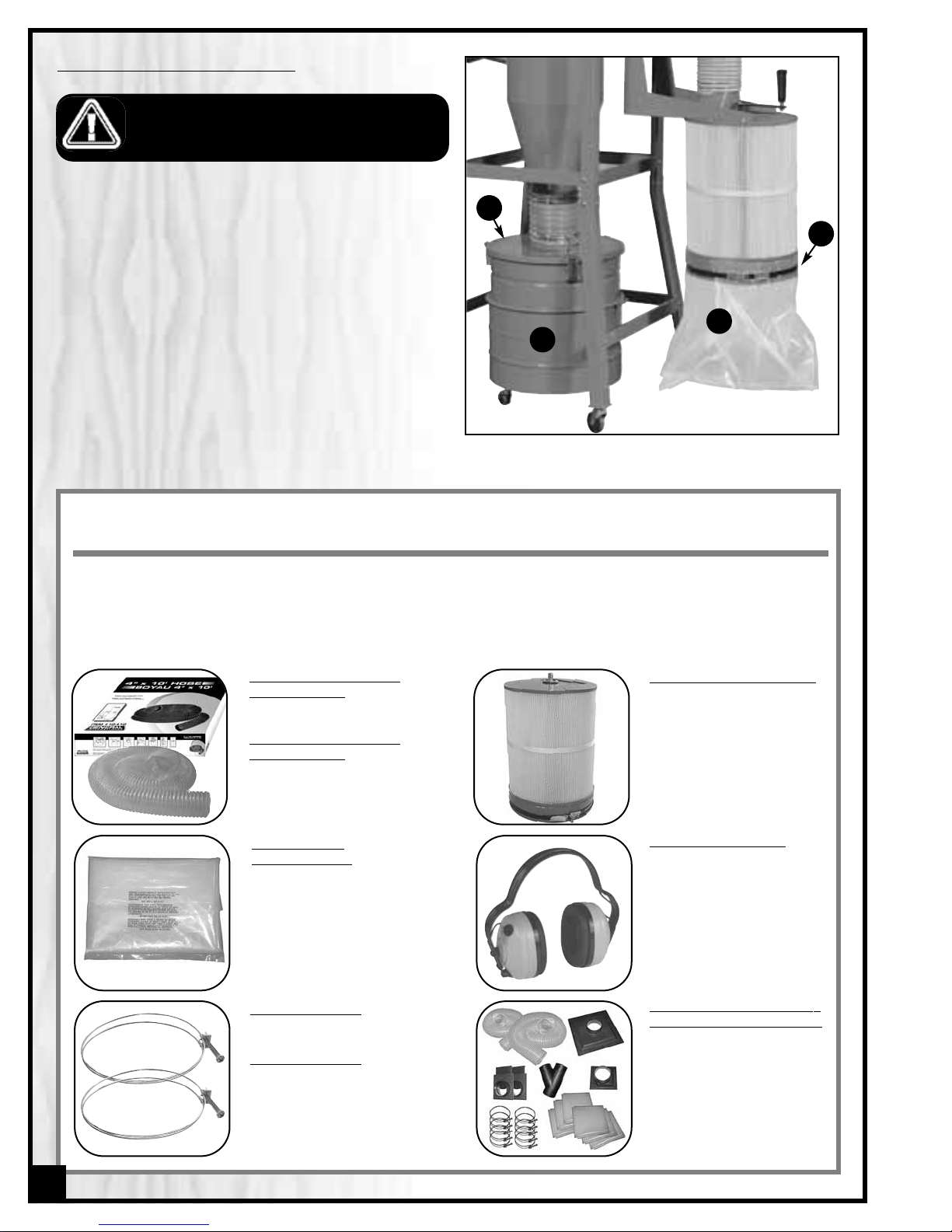
EMPTYING THE COLLECTOR BAG & DRUM
Note: Depending on your needs, shop situation and local regulations collections bags can be emptied and re-used or disposed (with their contents) and replaced with a new bag.
1. Turn off and unplug the machine.
2. Unclip the bag clamp A and remove the bag B from
the machine, or unclip the drum lid C and roll the
drum D out from beneath the machine.
3. Empty the drum and/or the bag (or simply dispose of
the bag and it's contents and replace with a new
bag) disposing of the contents in a safe and responsible manner that complies with all local codes and
regulations regarding waste disposal.
4. Re-install the drum and/or a bag and re-attach the
clamp.
4”
x 50’ Polyethylene
Flexible Hose
#10-130
5”
x 50’ Polyethylene
Flexible Hose
#10-135
Clear Plastic
Collector Bag
#10-819
Hose Clamps 4”
#10-089
Hose Clamps 5”
#10-090
Dust Collector
Accessory
Kit Two Machine Hook-Up
#10-200
(2) 4”x 10’Polyethylene flexible hose.
(1) 4” Universal dust hood outlet.
(1) Table saw dust hood.
(2) 4” blast gates
(1) 4”“Y” fitting.
(10)4” wire bail hose clamps.
(6) Heavy duty clear plas tic col-
lector bags.
Electronic Ear
muffs
#99-200
Highly efficient noise
reduction to help protect
your hearing when
operating power tools.
1 Micron Canister Filter
#10-806
RECOMMENDED OPTIONAL ACCESSORIES
We offer a large variety of products to help you increase convenience, productivity ,accuracy and safety when
using your Dust Collector. Here’s a small sampling of optional accessor ies available from your local General
International dealer.
For more information about our products, please visit our website at www.general.ca
20
B
C
D
A

1
2
1A
2B(12)
7A(4)
7B(4)
8B
8A
9
10A
10B
10C
10
D
11A(4)
11B(4)
11C(8)
11D(4)
1
1
10
8C
8D(2)
8
9C
9E(3)
9F(6)
10F
(6)
10E(3)
14B(8)
14A(4)
12(4)
14(4)
13(4)
15(3)
5(2)
5B(24)
5A(24)
4C(4)
4B(4)
4A
16A(4)
16B(4)
20A(4)
20B(4)
30
3
4
6
7
18A
18B
18C
18
18D
18E
19A(4)
19B(4)
19C
19
19D
20
22A(16)
22B(32)
22C(4)
22(4)
22D(16)
23C(4)
23B
23A
23
21
17
16
12B(60)
12A(38)
1B(4)
1C(4)
3A
3B
9A
9B(2
)
9G
24A
(4)
24B(4)
24
25
25A(2)
2A(12)
29
28
31
1
0G(6)
1
4C
(4)
12C(22)
20C
28A
28B
28C
32A(3)
32
29B(4)
29A(4)
32B
7C
2
C
4D
20D
29C
26
27(2)
DIAGRAM
21

22
PAR TS LIST
10-800CF M1
PAR T N0. DESCRIPTION SPECIFICATION QTY
10801-01 MOTOR 1.5 HP 1
10801-01A MOTOR GASKET 1
10801-01B FLAT WASHER 5/16”x OD18 x 2T 4
10801-01C HEX HEAD BOLT 5/16”x 3/4” 4
10801-02 MOTOR BASE PLATE 1
10801-02A FLAT WASHER 1/4”x OD19 x 2t 12
10801-02B HEX HEAD BOLT 1/4" x 1/2" 12
10801-02C GASKET 3 x 6mm x1.3M 1
10801-03 IMPELLER 330 1
10801-03A FLAT WASHER 5/16" x OD30 x 3T 1
10801-03B HEX HEAD BOLT 5/16" x 3/4" 1
10801-04 BLOWER HOUSING 1
10801-04A BLOWER OUTLET Ø 6” 1
10801-04B FLAT WASHER 1/4" x OD19 x 2t 4
10801-04C HEX HEAD BOLT 1/4" x 1/2" 4
10801-04D BLOWER GASKET 3 x 6mm x 0.8M 1
10801-05 BLOWER PANEL-LEFT/RIGHT 2
10801-05A FLAT WASHER 1/4" x OD19 x 2t 24
10801-05B HEX HEAD BOLT 1/4" x 1/2" 24
10801-06 REAR BLOWER PANEL Ø240 x 240L 1
10801-07 AIRFLOW PIPE 1
10801-07A FLAT WASHER 1/4" x OD19 x 2t 4
10801-07B HEX HEAD BOLT 1/4" x 1/2" 4
10801-07C PIPE GASKET 3 x 6mm x 0.8M 1
10801-08 CYCLONE SEPARATOR 1
10801-08A HEX HEAD BOLT 1/4" x 1/2" 10
10801-08B FLAT WASHER 1/4" x OD19 x 2t 10
10801-08C FLEXIBLE HOSE 7" x 18cm 1
10801-08D HOSE CLAMP Ø 180 mm 2
10801-09 DRUM LID Ø 420 x 60 1
10801-09A PHILLIPS HEAD SCREW 1
10801-09B SPROCKET WASHER 3
10801-09C GROUNDING WIRE 1
10801-09E DRUM LID LATCH 3
10801-09F POP RIVET A180-10D-5-2 6
10801-09G COPPER NUT 1
10801-10 UPPER DRUM Ø 500 x 200 1
10801-10A RUBBER SEAL 1.6M 1
10801-10B HEX NUT 5/16" 1
10801-10C DRUM CLAMP 1
10801-10D HEX HEAD BOLT 5/16" x 3" 1
10801-10E LATCH 3
10801-10F PHILLIPS HEAD BOLT 3/16" x 3/8" 6
10801-10G HEX NUT 3/16" 6
10801-11 LOWER DRUM Ø 500 x 300 1
10801-11A HEX NUT 3/8" 4
10801-11B LOCK WASHER 3/8" 4
10801-11C FLAT WASHER 3/8" x OD23 x 2t 8
10801-11D 2“ CASTER 4
10801-12 UPPER LEG 4
10801-12A HEX HEAD BOLT 1/4" x 1/2" 38
10801-12B FLAT WASHER 1/4" x OD19 x 2t 60
10801-12C HEX NUT 1/4" 22
10801-13 UPPER CROSS BRACE 4
10801-14 LOWER LEG 4

23
PAR TS LIST
10-800CF M1
PAR T N0. DESCRIPTION SPECIFICATION QTY
10801-14A 3”CASTER 4
10801-14B FLAT WASHER 3/8" x OD23 x 2t 8
10801-14C LOCK NUT 3/8" 4
10801-15 LOWER CROSS BRACE 3
10801-16 CANISTER HANGER-1 1
10801-16A HEX HEAD BOLT 1/4" x 1/2" 4
10801-16B FLAT WASHER 1/4" x OD19 x 2t 4
10801-17 CANISTER HANGER-2 1
10801-18 SHAKER ARM 1
10801-18A HEX HEAD BOLT 5/16" x 3/4" 1
10801-18B FLAT WASHER 5/16" x OD23 x 2t 1
10801-18C HANDLE 1
10801-18D FLAT WASHER 3/8" x OD23 x 2t 1
10801-18E LOCK NUT 3/8" 1
10801-19 BEARING 1
10801-19A HEX HEAD BOLT 1/4" x 5/8" 4
10801-19B FLAT WASHER 1/4" x OD13 x 1t 4
10801-19C C-RING Ø20 1
10801-19D SEAL 1
10801-20 CANISTER FILTER (SEE 10-806) Ø400 x 500L 1
10801-20A HEX HEAD BOLT 3/8" x 3/4" 4
10801-20B FLAT WASHER 3/8" x OD23 x 2t 4
10801-20C GASKET 3/8" x OD23 x 2t 1
10801-20D GASKET 3x6 mm x 0.8M 1
10801-21 SPINDLE 1
10801-22 FLAPPER ARM 4
10801-22A HEX HEAD BOLT 1/4" x 5/8"L 16
10801-22B FLAT WASHER 1/4" x OD13 x 1T 32
10801-22C FLAPPER 4
10801-22D LOCK NUT 1/4" 16
10801-23 FLAPPER BASE PLATE 1
10801-23A HEX HEAD BOLT 5/16 x 3/4" 1
10801-23B FLAT WASHER 5/16" x OD23 x 2t 1
10801-23C METAL SCREW M4 x 12mm 4
10801-24 CANISTER INLET MANIFOLD 6" 1
10801-24A HEX HEAD BOLT 1/4" x 1/2" 4
10801-24B FLAT WASHER 1/4" x OD13 x 1t 4
10801-25 FLEXIBLE HOSE (GRAY) Ø 6" x 510 1
10801-25A HOSE CLAMP Ø 6" 2
10801-26 BAG CLAMP Ø 400 1
10801-27 PLASTIC COLLECTOR BAG (SEE 10-819) Ø40cm x 60cmx 0.15mm 2
10801-28 CONTROL PANEL 1
10801-28A IC BOARD 1
10801-28B SWITCH TR26 1
10801-28C BREAKER 1
10801-29 SWITCH HOUSING BOX 1
10801-29A PHILLIPS HEAD SCREW 3/16 x 3/8" 4
10801-29B HEX HEAD BOLT 3/16" 4
10801-29C POWER CORD W/ PLUG 1
10801-30 REMOTE CONTROL 1
10801-31 GASKET 3x6 x1.3M 1
10801-32 Y INLET 1
10801-32A METAL SCREW M4 x 15mm 3
10801-32B 4”RUBBER CAP 1

WIRING DIAGRAM
24

25
Notes

IMPORTANT
When ordering replacement parts, always give the model number, serial number of the machine and
part number. Also a brief description of each item and quantity desired.
8360 Champ-d’Eau, Montreal (Quebec) Canada H1P 1Y3
Tel.: (514) 326-1161
Fax: (514) 326-5565 - Parts & Service / Fax: (514) 326-5555 - Order Desk
orderdesk@general.ca
www.general.ca
MODEL 10-800CF M1
 Loading...