

Page 1

Manufactured under license from Dolby Laboratories Licensing Corporation.
The ‘Double-D’ symbol is a trademark of Dolby Laboratories.
This product contains one or more programs protected under international and U.S. copyright laws as unpublished
works. They are confidential and proprietary to Dolby Laboratories Licensing Corporation. Their reproduction or
disclosure, in whole or in part, or the production of derivative works therefrom without the express permission of
Dolby Laboratories Licensing Corporation is prohibited. Copyright 1992–1996 by Dolby Laboratories, Inc. All
rights reserved.
This unit may be used for the decoding of DigiCipher® II television signals, but only if the receipt of
DigiCipher® II television signals has been authorized by relevant program providers.
DigiCipher® is a registered trademark of General Instrument Corporation.
Portions of this product are manufactured and sold under license from General Instrument Corporation for U.S.
Patent Nos. 4,613,901, 4,634,808, 4,712,238, 4,792,973, 4,864,615, 4,933,898, 5,144,664, 5,606,616, 5,485,577,
5,081,680, 4,975,951, 5,083,293, 5,111,504, 5,671,276 and other patents issued or pending.
© 1996–1999 General Instrument Corporation. All rights reserved.
The unauthorized modification, sale or use of any Access Control and Encryption module (ACE) contained herein is
prohibited
by law. Any such modification or alteration of this product or any unauthorized reception of television programming
could
subject the user and/or party modifying the ACE to fines, imprisonment and civil damages.
Page 2
Safety Considerations
SAFETY CONSIDERATIONS
RISK OF ELECTRICAL SHOCK
AVIS – RISQUE DE CHOC ELECTRIQUE
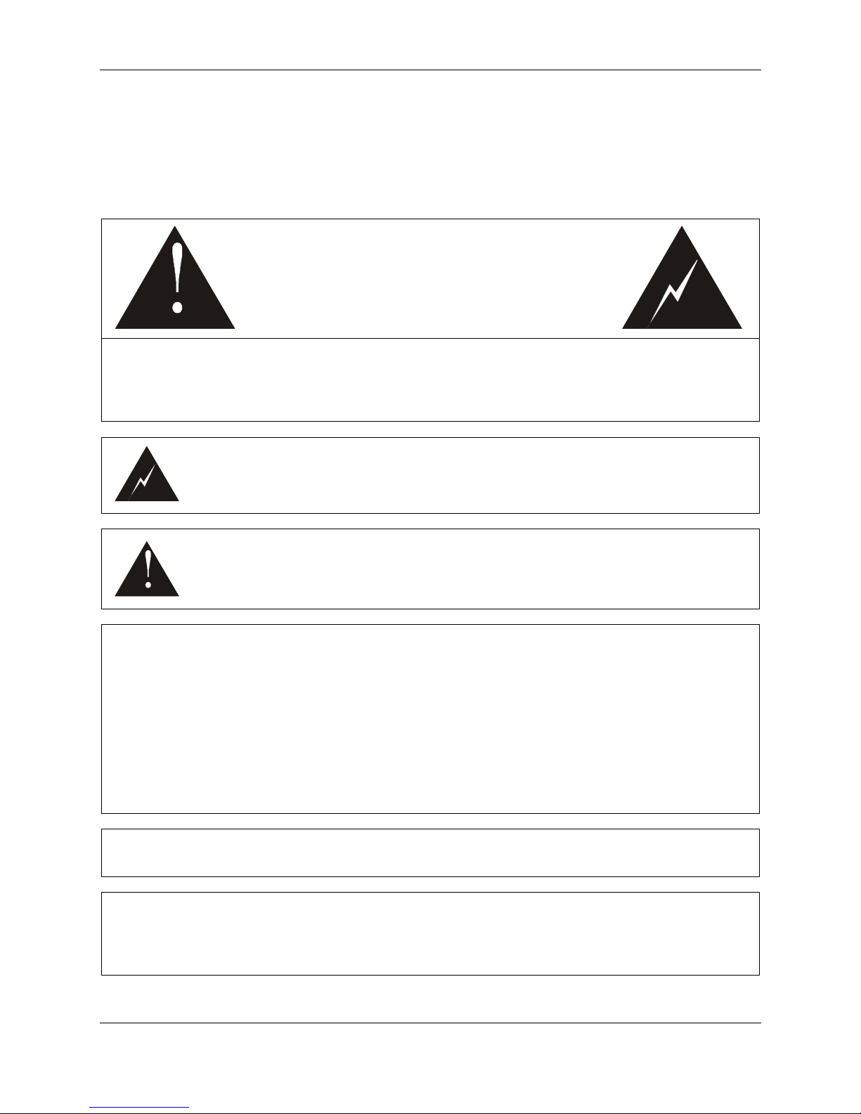
This symbol means that dangerous voltages are present within the equipment. These
voltages are not insulated and may be of sufficient strength to cause serious bodily
injury if touched. This symbol may also appear on schematics.
CAUTION
Do Not Open
Ne Pas Ouvrir
This symbol calls attention to a critical procedure or means that refer you to the
instruction manual for operating or service information. Only qualified service
personnel are to install or service the equipment. This symbol may also appear in text
and on schematics.
WARNING:
CAUTION:
To reduce the risk of fire or electrical shock, do not expose this equipment to rain or
moisture.
To prevent electrical shock, do not use the receiver electrical power plug (polarized with
an extension cord, receptacle or other outlet) unless the blades can be fully inserted to
prevent blade exposure.
The unauthorized modification of any decoder and the sale and use of any such decoder
is prohibited by law. Any such modification or alteration of this product or any
unauthorized reception of television programming could subject the user and/or seller
and/or party modifying the decoder to fines, imprisonment and civil damages.
To reduce the risk of electrical shock, do not remove cover. Refer servicing to qualified
service personnel. This installation should be made by a qualified service person.
ATTENTION: This commercial unit is intended for the decoding of DigiCipher
commercial use. Possession of this device does not enable or entitle the possessor to
receive DigiCipher®II television signals. Contact program providers to obtain
appropriate authorizations.
®
II television signals for
ii
Page 3
Safety Considerations
NOTE: This equipment has been tested and found to comply with the limits for a Class A digital device,
pursuant to Part 15 of the FCC Rules. These limits are designed to provide reasonable protection against
harmful interference when the equipment is operated in a commercial environment. This equipment
generates, uses and can radiate radio frequency energy and, if not installed and used in accordance with
the instruction manual, may cause harmful interference to radio communications. Operation of this
equipment in a residential area is likely to cause harmful interference in which case the user will be
required to correct the interference at his own expense. This digital apparatus does not exceed the Class A
limits of radio noise emissions from digital apparatus set out in the Radio Interference Regulations of the
Canadian Department of Communications.
MULTIPLE VOLTAGE EQUIPMENT:
The power cord included with your unit is for use with standard 125V AC supplies. If it is necessary to
operate the product in the U.S.A. with a 220V AC supply, then a UL-Listed power cord must be used and
the internal power supply jumper must be set. For countries outside the U.S.A. it is required to use a
power cord that complies with the electrical standards established by that country.
See IMPORTANT SAFEGUARDS for additional safety instructions.
iii
Page 4

Important Safeguards
IMPORTANT SAFEGUARDS
1. Read These Instructions First:
Read all safety and operating instructions before
installing or operating this equipment.
2. Retain This Instruction Manual:
Retain safety and operating instructions for
future reference.
3. Heed Warnings:
Adhere to all warnings on the equipment and in
this manual.
4. Follow Instructions:
Follow all operating and use instructions.
5. Cleaning:
Unplug the equipment from the AC power
source before cleaning.
DO NOT use liquid or aerosol cleaners.
6. Attachments:
ONLY use manufacturer recommended
attachments. Use of other attachments may cause
a hazard.
7. Water and Moisture:
DO NOT operate the equipment in highhumidity areas.
8. Accessories and Location:
DO NOT place this product on an unstable cart,
stand, tripod, bracket or table. The product may
fall causing serious injury and serious damage to
the product. Use only with a cart, stand, tripod,
bracket or table that is recommended by the
manufacturer or sold with the product. Any
mounting of the product should follow the
manufacture’s instructions and should use a
mounting accessory recommended by the
manufacturer.
9. Ventilation:
DO NOT block or obstruct slots or openings in
the equipment chassis. These openings provide
ventilation, ensure reliable operation of the
equipment and protect it from overheating.
10. Environment:
NEVER place this equipment near or over a
radiator or heat register.
DO NOT operate this equipment in an area
where proper ventilation is not provided.
11. Power Sources:
ONLY operate this product from the type of
power sources indicated in this manual or on the
appropriate marking label.
12. Grounding or Polarization:
This product may be equipped with a polarized
AC line plug (i.e., a plug having one blade wider
than the other). This plug will fit into the power
outlet only one way. If you are unable to fully
insert the plug into the outlet, try reversing the
plug. If the plug should still fail to fit, contact an
electrician to replace the obsolete outlet. This is
a safety feature, DO NOT attempt to defeat the
purpose of this safety feature.
13. Power Cord Protection:
Route power cords so that they are not likely to
be walked on or pinched by items placed on or
against them. Pay particular attention to cords at
plugs, outlets and the point where they exit from
the product.
14. Outdoor Antenna Grounding:
If an outside antenna or cable system is to be
connected to the product, be sure the antenna or
cable system is grounded as to provide some
protection against voltage surges and build-up
static charges.
v
Page 5

Safety Considerations
Section 810 of the National Electrical Code,
ANSI/NFPA No. 70 provides information with
respect to proper grounding of the lead-in wire
to an antenna discharge unit, size of grounding
conductor, location of antenna discharge unit,
connection to grounding electrodes and
requirements to grounding electrodes.
15. Lightning:
For added protection for this product during a
lightning storm, or when the product is left
unattended and unused for long periods of time,
unplug the product from the wall outlet and
disconnect the antenna or cable system. This will
prevent damage to the video product due to
lightning and power line surges.
16. Power Lines:
DO NOT locate the outside antenna in the
vicinity of overhead power lines, or where it can
fall into such power lines or circuits. When
installing an outside antenna system, take
EXTREME CARE to keep from touching such
power lines or circuits as contact with them may
be fatal.
17. Overloading:
DO NOT overload wall outlets or extension
cords as this can result in fire or electrical
shock.
18. Object and Liquid Entry:
NEVER push objects of any kind into the slots
or openings of this product. Objects may be
exposed to dangerous voltage points. This may
also short out parts and may result in fire or
electrical shock.
DO NOT pour liquid of any kind into the slots or
opening of this product.
19. Servicing:
DO NOT attempt to service or repair this
product yourself. There are no user serviceable
parts in this product. Opening or removing the
chassis covers may expose you to dangerous
voltages. Refer all servicing to qualified
technical personnel.
20. Damage Requiring Repair:
§ When the power supply cord or plug is
damaged.
§ If the product has been exposed to water or
rain.
§ If liquid of any kind has been spilled, or
objects of any kind have fallen into the
product.
§ If the product does not perform normally by
following the operating instructions.
– Adjust only those controls that are
covered in this Operating Manual. An
improper adjustment of other controls
may result in damage or misalignment,
often requiring extensive corrective
action by a qualified technician.
§ If the product has been dropped or the
chassis has been damaged.
§ If the equipment exhibits a distinct change in
performance. (This may indicate a need for
service.)
21. Replacement Parts:
When replacement parts are required, make sure
the qualified technician uses only those parts
recommended by the manufacturer.
Unauthorized use of parts or substitutions may
result in fire, electrical shock or improper
operation of the product.
22. Safety Check:
Upon completion of any service or repair to the
product, ask the qualified technician to perform
safety checks to ensure the product is in proper
working condition.
23. Note to System Integrators:
This reminder is provided to call the system
integrator’s attention to Article 820-40 of the
NEC. This article provides guidelines for proper
grounding and, in particular, specifies that cable
ground shall be connected to the grounding
system of the building, as close as possible to the
point of cable entry as practical.
vi
Page 6

Page 7

Table Of Contents
TABLE OF CONTENTS
SAFETY CONSIDERATIONS II
IMPORTANT SAFEGUARDS V
TABLE OF CONTENTS VII
CHAPTER 1
INTRODUCTION................................................................................................................................................ 1
WHAT ARE VIRTUAL CHANNELS?.............................................................................................................. 1
CHAPTER 2
THE DSR-4800 SERIES......................................................................................................................................2
THE DSR-4800.................................................................................................................................................. 3
THE DSR-4810.................................................................................................................................................. 4
THE DSR-4850.................................................................................................................................................. 5
CHAPTER 3
SPECIFICATIONS..............................................................................................................................................6
DSR-4800.......................................................................................................................................................... 6
CHAPTER 4
INVENTORY AND INSTALLATION................................................................................................................ 9
INVENTORY.................................................................................................................................................... 9
MOUNTING...................................................................................................................................................... 9
POSITIONING..................................................................................................................................................9
CHAPTER 5
FRONT PANEL CONTROLS AND MENU DISPLAY ................................................................................... 11
FRONT PANEL............................................................................................................................................... 11
EDITING AND MENU CONFIGURATION.................................................................................................... 14
TO EDIT MENU INFORMATION: ............................................................................................................ 14
NAVIGATING THE MENU DISPLAY........................................................................................................... 14
STATUS MENU:........................................................................................................................................ 15
PROGRAMS MENU:................................................................................................................................. 15
PRESETS MENU:...................................................................................................................................... 19
RF MENU:................................................................................................................................................ 19
VIDEO MENU: ......................................................................................................................................... 22
AUDIO MENU:......................................................................................................................................... 23
REMOTE MENU:...................................................................................................................................... 25
TIMERS MENU:........................................................................................................................................ 26
DATA MENU: ........................................................................................................................................... 26
CONFIG MENU:....................................................................................................................................... 27
ALARMS MENU:....................................................................................................................................... 31
SAVE MENU:............................................................................................................................................ 32
CHAPTER 6
REAR PANEL AND CONNECTORS............................................................................................................... 33
vii
Page 8

Table Of Contents
REAR PANEL................................................................................................................................................. 33
CONNECTING THE CONNECTORS............................................................................................................. 36
AC POWER INPUT................................................................................................................................... 36
EIA 232 ASYNC DATA .............................................................................................................................. 36
EIA 232/485 LOG/REMOTE...................................................................................................................... 36
#1 & #2 DIGITAL AUDIO........................................................................................................................ 36
#1 - #4 RF INPUT...................................................................................................................................... 36
ETHERNET............................................................................................................................................... 37
ASI OUTPUT............................................................................................................................................. 37
4:2:2 SDI................................................................................................................................................... 37
TERMINAL STRIP..................................................................................................................................... 37
CHAPTER 7
LANGUAGE ABBREVIATIONS ..................................................................................................................... 38
CHAPTER 8
PRODUCT SUPPORT & EQUIPMENT RETURNS.......................................................................................39
IF YOU NEED HELP...................................................................................................................................... 39
REPAIRING PROCEDURES: ......................................................................................................................... 39
WARRANTY.....................................................................................................................................................40
viii
Page 9

Introduction
CHAPTER 1
INTRODUCTION
General Instrument DSR-4800 digital satellite receivers are integrated
receiver/decoders (IRD) designed for broadcast networks, cable systems and
other commercial satellite operations. They are simple to use as they allow the
program provider to perform many of the complex setup tasks. The receivers can
then receive these instructions from the satellite as part of the downloaded digital
signal. They can be configured to your exact needs using the front panel menus.
WHAT ARE VIRTUAL CHANNELS?
It is important to understand how virtual channels work before using the
front panel menus.
When you manually tune to a transponder and select a programmer’s VCT
number and channel designation, the receiver will download the VCTs
available on that transponder. For example, a programmer may have one
VCT for his consumer network and a different VCT for his commercial
customers. You can accept several VCTs in memory. When you download
more tables, the table that is not used for the longest period of time is
discarded first. The number of VCTs retained depends upon table size, but
there is typically room for five or more commercial network tables.
The DigiCipher® II network and its VCT can be limited to part of one
transponder, one entire transponder, many transponders on one satellite or
many transponders on several satellites. The units have four antenna satellite
input ports that can connect to antennas aimed at two different satellites.
Since the VCTs include satellite and transponder (frequency) information,
the receiver will change satellite and transponder as needed when the virtual
channel on the front panel is changed. The receiver will give an error
message on the front panel LCD if the VCTs prompt it to change to a
satellite/transponder that it cannot find on the input ports.
At most, each virtual channel has only one video data stream. Some virtual
channels have audio or data-only services. The virtual channel may have
many audio elements, and they are selected by language: English (stereo
implied) and French-Portuguese (mono-mono) are just a sample of the 256
possibilities. The IRDs have enough memory to accept a download of 64
languages in a network. In the case of mono-mono (French-Portuguese for
example), the left output is the first mono (French), and the right output is the
second mono (Portuguese). If you specify a language that is not available, the
audio defaults to the first in the VCT list–usually selected by the programmer
because it matches the video lip movements.
1 DSR-4800 Operating Manual
Page 10

The DSR-4800 Series
CHAPTER 2
THE DSR-4800 SERIES
The General Instrument DSR-4800 series of digital satellite receivers
includes the DSR-4800, DSR-4810 and the DSR-4850. The aforementioned
products are hereinafter referred to as “unit.”
DSR integrated receiver/decoders are designed for broadcasters and other
professional, contribution-quality commercial satellite operations. They can
be very simple to use as they allow the program provider to perform many of
the complex setup tasks. The receivers can receive instructions from the
satellite as part of the downloaded digital signal, or you can configure it to
your exact needs using the extensive front panel menus.
All units contain the following key features:
, The microprocessors and memory built into each unit decodes and
decompresses the MPEG-2 video, audio, data and other information in
the signal. This significantly decreases the amount of information to be
transmitted thereby reducing bandwidth requirements. Broadcasters and
programmers can transmit on one carrier any number of channels,
limited only by the material transmitted and their particular network
needs.
, Delivery of the best possible video and audio quality by using forward
error correction (FEC) techniques that make allowances for poor signal
quality. FEC determines which information is corrupted, then corrects it.
As a result, the digital signal remains clear until the signal quality
degrades to a level where FEC can no longer restore the information.
This threshold is below an analog receivers’ ability to provide
recognizable video.
, Based on MPEG-2 standards, we use virtual channel mapping to select
the desired video, audio and other data streams out of the overall
transmission.
, Virtual channel information can be determined over the satellite at any
time, allowing for dynamic changes in the network without requiring you
to reconfigure the receiver.
, Automatically handles fixed, limited-statistical and full-statistical
multiplexing to provide the best video performance.
, For audio compression, we use the Dolby
techniques chosen by the North American Grand Alliance for High
Definition Television and for the newest digital videodisk systems. The
DSR-4800 Operating Manual 2
®
Digital compression
Page 11

The DSR-4800 Series
receiver automatically adjusts to the compression rate used for the audio.
In the DVB mode, the unit is capable of processing DVB Musicam
audio.
, Non-volatile memory to indefinitely recall the operating configuration
when power fluctuates, is interrupted or removed altogether.
, Security features, including General Instrument’s proven security
system. Even though the unit does not require a TvPass™ Card to
operate with security, in the unlikely event that the code is compromised,
security can be renewed by simply inserting a card with a new code into
the receiver.
, A low profile, single rack unit design – only 1.75” EIA rack space.
, Able to process and provide the broadcast engineer with a 4:2:2 Studio
Profile @ Main Level digital video output from a DigiCipher® II or DVB
signal.
, The front panel display and edit/select control are formatted to provide
optimum resolution, execution and the most effective display of
information necessary for operation.
, Controllable or status monitored via either of two separate data interfaces
or by way of satellite network control.
, The unit’s EIA232/485 rear panel control interface can be configured to
directly plug and play with your existing network control system.
, A complete set of extended commands allow for remote control of all the
receiver’s additional controls and functions.
, Ability for network monitoring and control via a 10Base-T Ethernet
connection.
, All units offer output of ASI, digital video (i.e., SMPTE259 with
embedded four-channel audio), digital audio, analog video, analog audio,
VBI lines and closed caption.
THE DSR-4800
The General Instrument DSR-4800 receives both HD and SD signals. Both
HD and SD streams are reprocessed to the Digital Video Broadcast
Asynchronous Serial Interface format at 270 Mbps. The ASI signal is output
through a BNC connector.
SD transport streams can be processed at 4:2:2 P/ML and 4:2:0 MP/ML
decompression.
The unit receives QPSK modulated signals at L-band frequencies of 950 to
2150 MHz through one of four input ports.
3 DSR-4800 Operating Manual
Page 12

The DSR-4800 Series
The DSR-4800 performs demodulation and FEC decoding of all standard
DigiCipher® II symbol and convolutional coding rates, at information rates
up to 40.46 Mbps. It also performs demodulation and FEC decoding of all
standard DVB convolutional coding rates, at information rates of 3.25–45
Msps. Within the resulting transport stream, a single DigiCipher® II service
designated by the user can be decrypted.
The DSR-4800 will automatically tune to of four L-band inputs based on the
Virtual Channel Tables sent from the UCS. The unit will use the Virtual
Channel Tables for tuning between services.
THE DSR-4801
The General Instrument DSR-4801 is a more economical version of the fullfeatured DSR-4800 designed for the studio monitoring, video processing and
satellite turnaround markets requiring 4:2:2 digital video output.
DSR-4801 receives both HD and SD signals. SD transport streams can be
processed at 4:2:2 P/ML and 4:2:0 MP/ML decompression.
The unit receives QPSK modulated signals at L-band frequencies of 950 to
2150 MHz through one of four input ports.
The DSR-4801 performs demodulation and FEC decoding of all standard
DigiCipher® II symbol and convolutional coding rates, at information rates
up to 40.46 Mbps. It also performs demodulation and FEC decoding of all
standard DVB convolutional coding rates, at information rates of 3.25–45
Mbps. Within the resulting transport stream, a single DigiCipher® II service
designated by the user can be decrypted.
The DSR-4801 will automatically tune to of four L-band inputs based on the
Virtual Channel Tables sent from the UCS. The unit will use the Virtual
Channel Tables for tuning between services.
The lack of a full-feature VBI board, ASI output and Ethernet control
distinguishes it from the DSR-4850.
THE DSR-4810
The General Instrument DSR-4810 includes all features of the DSR-4800
with the addition of video synchronization capability across multiple DSR4810 units. The unit will accept a primary and secondary video input
reference and synchronize the output audio and video to one of those
references. It will also provide a video output reference for other units to use
as a synchronization reference.
DSR-4800 Operating Manual 4
Page 13

The DSR-4800 Series
THE DSR-4850
The General Instrument DSR-4850 includes all features of the DSR-4800
with the following variance: An ASI input option has been installed in place
of the satellite QPSK tuner allowing the DSR-4850 to function as a decoder.
The DSR-4850 receives the MPEG-2 transport stream in DVB ASI format
through a BNC connector to an ASI input module. Once the ASI transport
stream is received either from a DSR-4800 or DSR-4810 unit, multiple DSR4850 units can be looped together.
DCII HD transport streams are processed to decrypt a service selected by the
user. The resulting transport stream is output in ASI format.
SD transport streams are processed to extract, decrypt and decompress a
service selected by the user.
The DSR-4850 will use the Virtual Channel Tables from the UCS for tuning
between common services.
5 DSR-4800 Operating Manual
Page 14

Specifications
CHAPTER 3
SPECIFICATIONS
DSR-4800
Mechanical
Height: 1.75” (44 mm) EIA Rack Space
Width: 19” (480 mm) EIA Rack Unit
Depth: 20” (503 mm)
Weight (estimate): 15 lbs
Power
Primary Input: 86/260V AC (switchable)
Line Frequency: 50/60 Hz
Power Consumption: 70 W (estimate)
Environmental
Humidity Range (non-condensing): 0 to 90%
Temperature Range (operational): 0 to +40° C
Temperature Range (survivable): -20 to +50° C
Rack Spacing: 1.75” (44 mm) above and below the unit
Altitude: 0 - 8000 Feet
Input Configuration
QPSK Demodulator (DCII & DVB)
Input Signal: 3.25 to 40.5 Msps
Input Frequency Range: 950 to 2150 MHz
Tuning Steps: 125 kHz
Input Level: -25 to –65 dBm
FEC Operating Modes: 5/11, 1/2, 3/5, 2/3, 3/4, 4/5, 5/6, 7/8
ASI MPEG-2 Output
Transport Stream Output: Asynchronous Serial Interface (ASI)
Data Format: Continuous
Data Rate: 270 Mbit/sec
Output Level: 1.0 vp-p +0 –200mV
Output Cable Line Drive: 400 ft RG6
ASI MPEG-2 Input (DSR-4850)
Format: ASI
Transmission: 270 MBit/Sec, both data packet and data burst
Standard: CENELEC EN 50083-9
Analog Audio (Baseband Dolby AC3 Output)
Output Impedance (differential pair with ground): 60 ohms
Total Harmonic Distortion (into 600 Ohms load): <0.5% at 1 kHz
L/R Gain In-Balance: <0.2 dB
DSR-4800 Operating Manual 6
Page 15

Specifications
Output Signal to Noise Ratio (A weighted): >86 dB
Sampling Rates: 44.1 and 48.0 kbps
Dolby Compression Rates: 32 to 640 kbps
Digital Audio
Output Impedance (differential pair with ground): 110 ohms
Output Level (non adjustable): Unity Gain
Total Harmonic Distortion: <0.2% at 1 kHz
L/R Gain In-Balance: <0.5 dB
Output Signal to Noise Ratio (A weighted): >90 dB
Crosstalk all Channels: -80 dB
Analog Video DC-II Mode
Output Level: +/- 2% / 1.0VP-P
Frequency Response (30Hz to 4.2MHz): 0.5 dB
Luminance Nonlinear Distortion: 3%
Video/Audio Delay: 5 nsec
Chroma Nonlinear Gain: 3%
Chroma Nonlinear Phase: 3%
Differential Gain (10% to 90% APL): 1%
Differential Phase (10% to 90% APL): 1 degree
C/L Gain Inequality: 3.0%
C/L Intermodulation: 3.0%
Luminance SNR (Unified Wgt): >58
Field Time Distortion: 3.0%
Line Time Distortion: 3.0%
VBI: CC & GI Provided Lines
4:2:0 Video Resolutions: 704, 528, 353, 720 544x480
4:2:2 Video Bit Rates: 1 to 20 Mbit
4:2:0 Video Bit Rates: 1 to 15 Mbit
4:2:2 Video Resolutions: 720, 544x480 and 720x512
Film Mode: On/Off
Copy Protection: On/Off
Analog Video DC-II Mode (continued)
Motion Prediction: Field and Dual Frame
B Frame Support: 2 and No B Frames
Digital Video
SMPTE259 Output Impedance: 75 ohm
Output Level: 800 mV (+/-50mV)
Output Jitter: <270 ps
Video/Audio Delay: +/- 5 msec
Embedded Audio (4 channel): ½ and ¾
4:2:0 Video Resolutions: 704, 528, 353, 720 544x480
4:2:2 Video Bit Rates: 1 to 20 Mbit
4:2:0 Video Bit Rates: 1 to 15 Mbit
4:2:2 Video Resolutions: 720, 544x480 and 720x512
Film Mode: On/Off
Copy Protection: On/Off
7 DSR-4800 Operating Manual
Page 16

Specifications
Motion Prediction: Field and Dual Frame
B Frame Support: 2 and No B Frames
Data Interfaces
Asynchronous Data Output: RS 232 9.6 to 19.2 kbps
Remote Control: RS 232/485 9.6 to 38.4 kbps
Ethernet: 10Base-T TCP/IP, SNMP
DSR-4800 Operating Manual 8
Page 17

Inventory and Installation
CHAPTER 4
INVENTORY AND INSTALLATION
To prevent damage and/or safety hazards, always handle the General
Instruments DSR unit with care and only according to instructions as laid out
in this Operations Manual.
INVENTORY
The shipping carton should contain the following items:
1. A DSR unit
2. A power cord
3. A set of decorative ear/screw covers
4. One (1) Allen wrench
5. Four (4) Allen screws
6. Two (2) Phoenix connectors (audio)
7. A Warranty Information Card
8. This Operations Manual
9. Other pertinent documentation and additional manual inserts
MOUNTING
The unit is designed for installation in a EIA standard 19-inch (480 mm)
equipment rack. When mounting it in the rack, use pan or round head screws
and washers in all four front panel mounting locations. This ensures a secure
mount for the size and weight of the unit. You must supply screws matching
your rack.
POSITIONING
, To prolong service life, pay special attention that the environment in
which the DSR unit is being used is free of dust and other airborne
particles.
, Make sure the DSR unit is operated in a temperature-controlled
environment. Never place a DSR unit near a heat source.
, Allow a 1.75-inch (44 mm) air gap above and below receivers for
cooling purposes, or alternate receivers with low-power consumption
9 DSR-4800 Operating Manual
Page 18

Inventory and Installation
equipment that does not block the top-to-bottom air flow of the receiver
chassis. Never install multiple units in such a way that the air intake from
one unit aligns with the outlet of another.
, Do not install a DSR unit in areas of high humidity or where there is any
danger of water infiltration.
, Do not run AC power cables and signal leads in the same duct so as to
avoid magnetic interference from the high-voltage cable.
DSR-4800 Operating Manual 10
Page 19
Front Panel Controls and Menu Display
5
3
4 (
261
7
OFFLINEF/P LOCKSI
G
OTE
ORIZERF LOCKEDBER
CHAPTER 5
FRONT PANEL CONTROLS AND MENU DISPLAY
FRONT PANEL
NOTE: Some information in this chapter is currently under development. As
such, it may not be properly reflected or else not included yet. Once the
information is finalized this document will be modified accordingly.
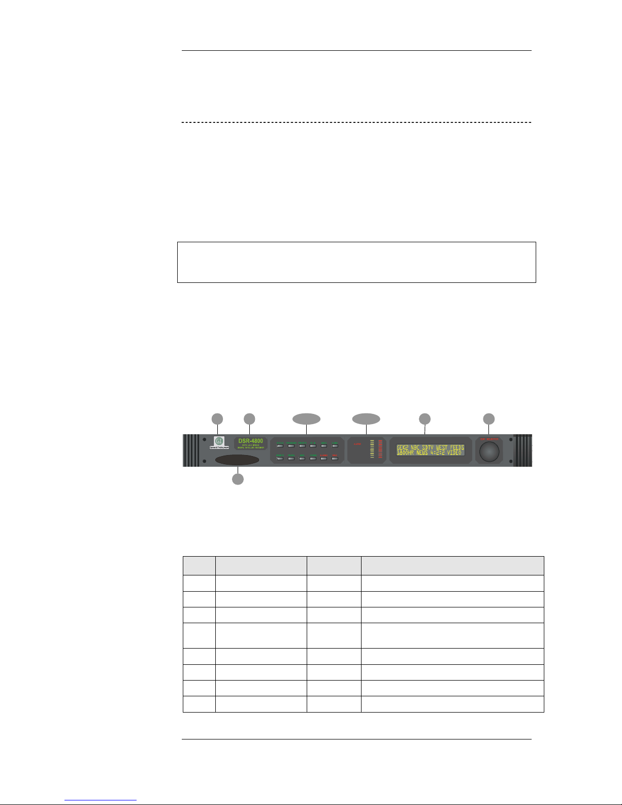
All operations described in this chapter require using the front panel, which
includes Manufacturer, Model Designation, Menu Controls, Operational
Status, Display and Edit Control.
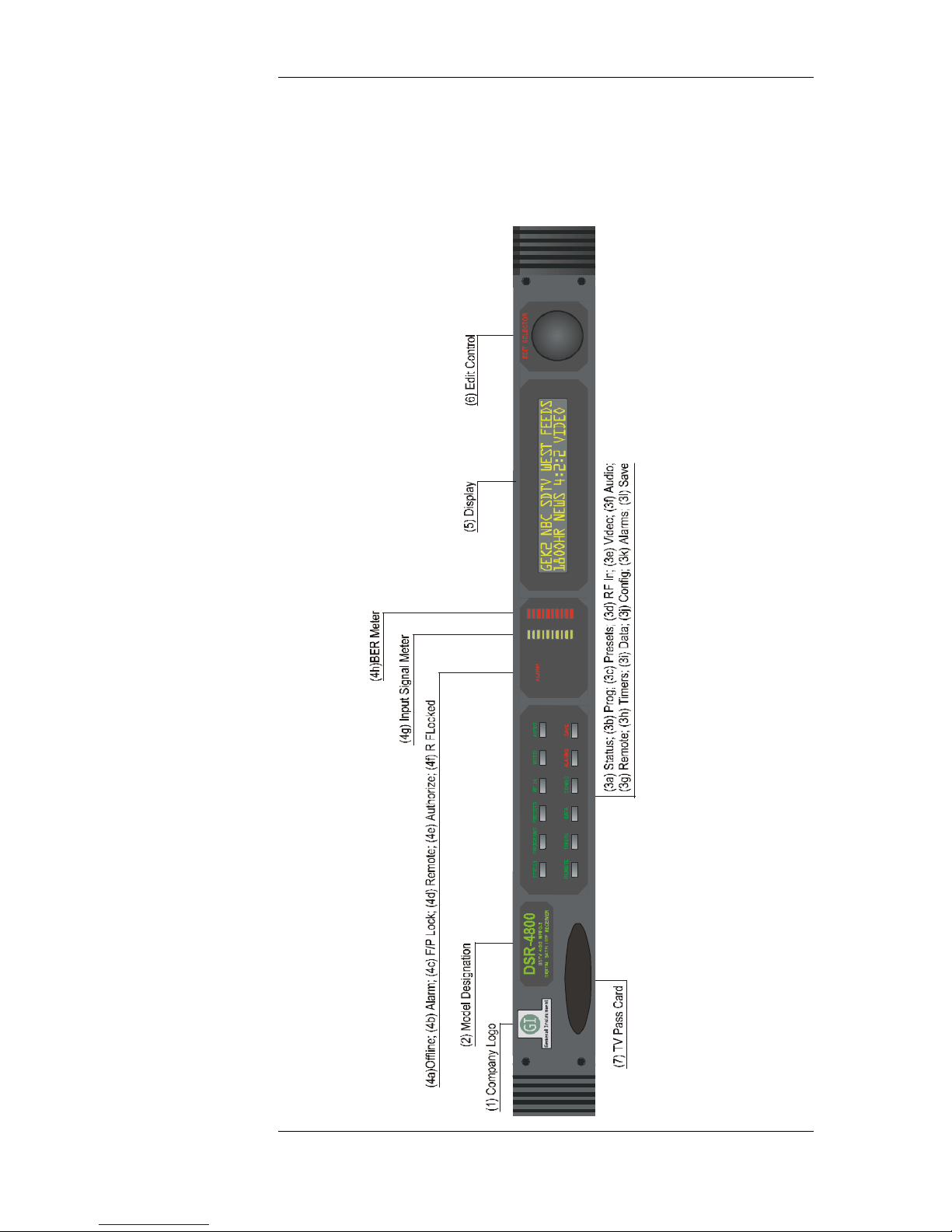
Figure 5-1
The Front Panel
(a-l)
a-h)
REM
AUTH
Table 5-2
The Front Panel
Key Control Type Description
1 Company Designation Label Indicates Manufacturer or OEM Supplier
2 Model Designation Label Indicates model name & product description
3 Menu Control s Group Menu selection area
3a STATUS – Green Push Button Displays satellite and programming information, or
3b PROG – Green Push Button Selects Virtual Channel Tables from Rom Tables
3c PRESETS – Green Push Button
3d RF IN – Green Push Button Displays antenna settings and satellite data
3e VIDEO – Green Push Button Displays video format settings
reverts to last saved setting if pushed while in edit mode
11 DSR-4800 Operating Manual
Page 20
Front Panel Controls and Menu Display
Key Control Type Description
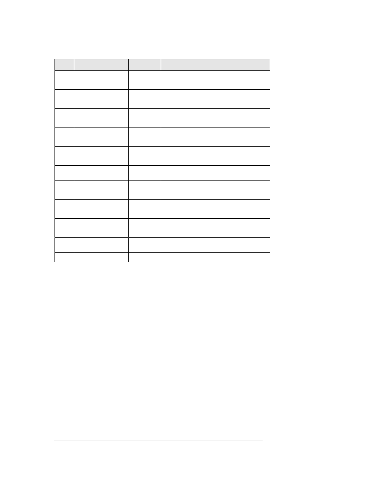
3f AUDIO – Green Push Button Displays audio level and format settings
3g REMOTE – Green Push Button Displays remote control port settings
3H TIMERS – Green Push Button
3I DATA – Green Push Button Displays async data port settings and tuner data
3J CONFIG – Green Push Button Displays firmware and hardware configuration data
3K ALARMS – Red Push Button
3L SAVE – Red Push Button Saves new settings to receiver memory
4 Operational Status Group Displays current operating conditions
4a Offline Illuminated Receiver is offline
4b Alarm Illuminated
4c F/P Lock Illuminated Front panel access & control is locked by the remote
4d Remote Illuminated Unit is being controlled via remote
4e Authorize Illuminated
4f RF Locked Illuminated Receiver is locked to incoming signal
4g Input Signal Meter Bar Graph Indicates input signal strength
4h BER Meter Bar Graph Indicates received signal bit error rate
5 Display See Chapter 6 for detailed menu operation
6 Edit Control Rotary/Push
Knob
7 TV Pass Card Provided renewable security interface
controller
Press to enable Edit function; rotate to select and change
settings
DSR-4800 Operating Manual 12
Page 21
Front Panel Controls and Menu Display
Figure 5-3
The Front Panel
R
E
IG
S
E
D B
E
E
IZ
R
LINE
O
F
MOT
E
TH
/P LOCK
OF
R
U
F
A
RF LOCK
13 DSR-4800 Operating Manual
Page 22

Front Panel Controls and Menu Display
EDITING AND MENU CONFIGURATION
The Menu Control, Display and Edit Control functions operate in harmony
allowing complete control of receiver operations. Refer Figure 5-1, Table 5-2
and Figure 5-3 for an illustration and description of the numerically
referenced Menu Control buttons below.
TO EDIT MENU INFORMATION:
1. Press any Menu Control button (3); the menu display screen presents
the corresponding field labels.
2. Rotate the Edit knob (6) to move the cursor under the field label you
wish to edit.
3. To enable the Edit function, press the Edit knob once; the word
EDIT, located above the Edit knob, becomes illuminated.
4. Rotate the Edit knob to change the data for that particular field.
5. Once the desired setting is displayed, press the Edit knob to exit the
editing mode; the lit word EDIT is extinguished.
6. The Save button (3l) is now illuminated.
7. To save the new setting to the receiver database, press the Save
button. If the save button is not pressed within 10 seconds, the
receiver will automatically press it for you and save the current
settings.
To revert to the prior settings:
If at any time during the edit function you wish to revert to the
previous settings, simply press the Status button and the former
settings will reappear.
Note: You only have 10 seconds to do this or the receiver will
automatically save the new settings.
NAVIGATING THE MENU DISPLAY
NOTE: As the menus continually evolve, updates will be provided in
addendum form.
The Front Panel Menu Controls display a series of push buttons that you can
use to configure and control your system. So that you can always identify
what you are looking at, the word above the active button is lighted. The
names of the fields available within that menu are displayed on the screen
located at the right side of the front panel. Below each field label is the
DSR-4800 Operating Manual 14
Page 23
Front Panel Controls and Menu Display
current setting for that field. Below is a detailed explanation of the fields
contained within each menu item on the front panel.
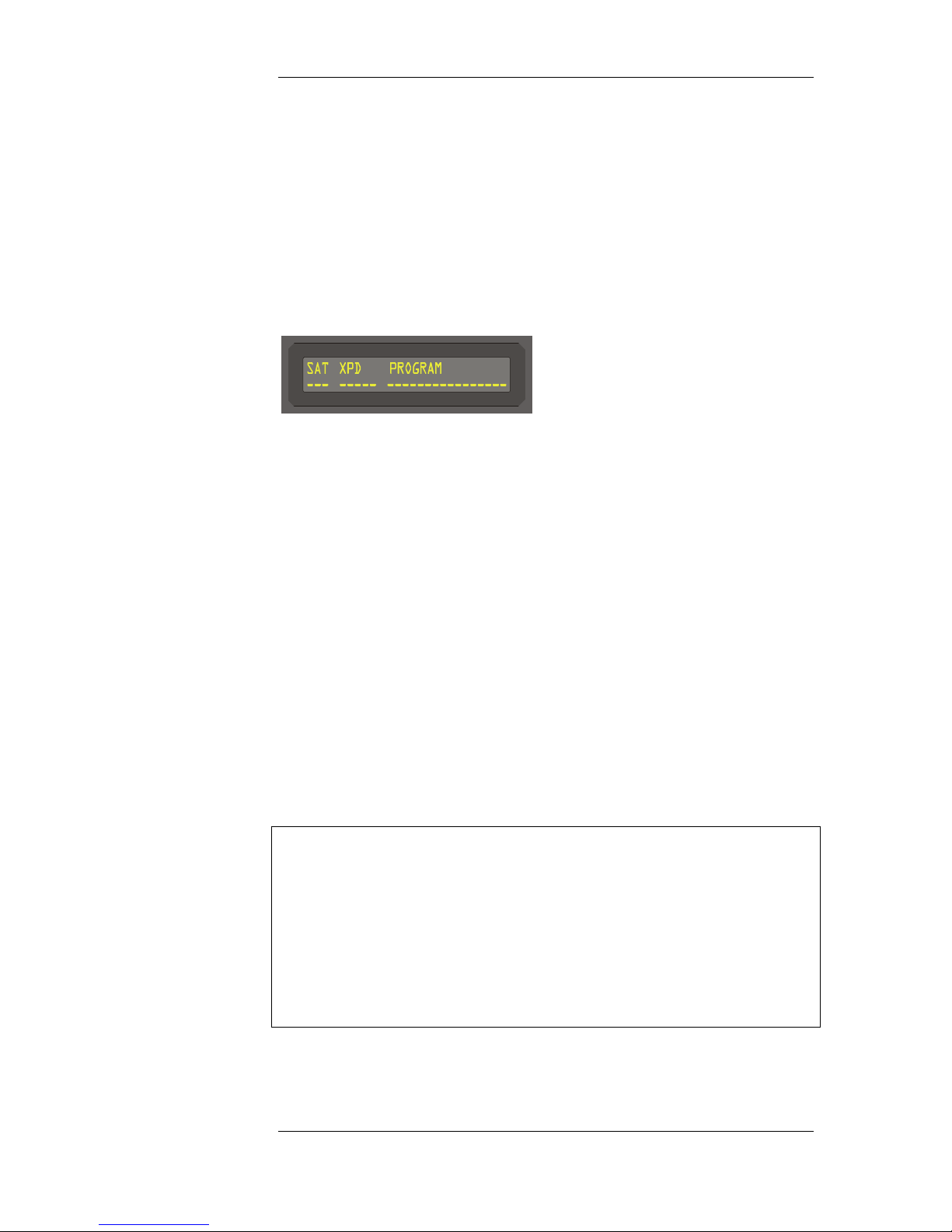
STATUS MENU:
DCII VCT Mode, DCII Manual Mode, DVB Mode (Read Only):
Display (EXT 1)
SAT
, A three (3) character field showing the first three characters of
the satellite_reference_name() as defined in the
Satellite Text Message.
XPD
, A five (5) character field showing the first four characters of the
corresponding transponder_name() as defined in the
®
Transponder Name Table.
PROGRAM
, A twelve (12) character field showing the first twelve characters
of the name() as defined in the Source Name Table.
PROGRAMS MENU:
NOTE: The Programs Menu has multiple functions, which depend on the
mode of operation that the receiver is placed in. The DSR-4800 has three
modes of operation, and the function of each field as related to the mode of
operation is shown below. To receive and demodulate a signal for the first
time, the receiver must be placed into DCII Manual or DVB mode. For the
DCII VCT mode to operate, the receiver must first be locked onto the desired
Programmers transport stream, after which a Virtual Channel Map is
downloaded to the receiver. This should take about 30 seconds. After the
map is downloaded the receiver automatically follows the virtual channel for
all settings of the receiver.
15 DSR-4800 Operating Manual
Page 24
Front Panel Controls and Menu Display
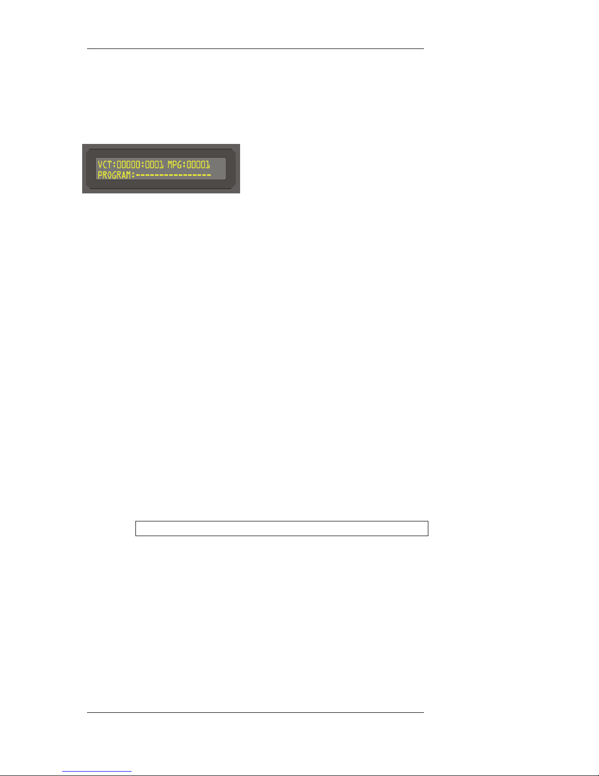
DCII VCT Mode :
Display (EXT 1)
VCT
, Tunes to an operator requested service by entering the VCT ID
(Dec) and the Virtual Channel Number (Dec). In DCII Manual
mode the desired VCT number and VC are directly entered. In
DCII VCT mode scrolling of the VCT-ID’s and VCT-Num’s are
available from the stored Virtual Channel Map Tables.
Corresponding Service Numbers are updated in the MPEG field.
In DVB mode the VCT and VC function is not available, so the
MPEG service number is used to select the desired program.
MPEG
, In DCII VCT mode this field displays the selected MPEG
service number updated when VCT information is entered (note
that this is a read only field in DCII VCT mode); in DCII
Manual or DVB mode this field permits scrolling to select
programming available in the selected transport stream. The
displayed program numbers are extracted from the MPEG
Program Map Table or the DCII defined Service Map Table.
, While in DCII VCT Mode, Service Numbers are actively related
to their Associated Virtual Channels. As such, the VCT is
updated when a valid VCT definition exists.
, Valid in DCII Manual mode and DVB mode.
Note: While in DVB mode, VCT information is not displayed.
PROGRAM
, A sixteen (16) character field showing the first sixteen characters
of the program name as defined in the Source Name Table.
DSR-4800 Operating Manual 16
Page 25
Front Panel Controls and Menu Display
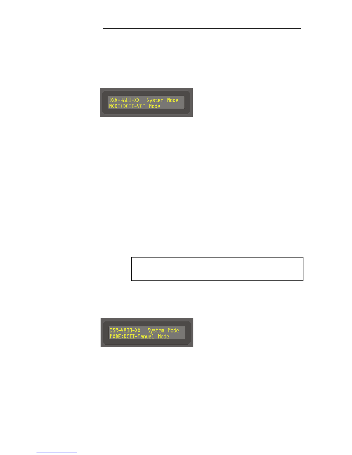
DCII-VCT Mode:
Display (EXT 2) Menu 1
DCII VCT MODE
, Displays the current operational mode that the receiver was
placed in.
, Use the Edit button to select from three modes of operation, (i.e.,
DCII VCT mode, DCII Manual mode or DVB mode.) After the
desired mode is selected press Program to scroll the menu back.
, When placed in DCII VCT Mode for the first time, the receiver
must have been first tuned in DCII Manual mode to select a valid
RF signal and received a virtual channel map. Proceed to DCIIManual mode for instructions.
, Once the receiver has a valid virtual channel map, first scroll
through the VCT field and select the desired virtual channel table
number for the program you wish to select. The receiver will
automatically tune to the desired program and start the decoding
process.
Note: If the VCT number for the program you want is not listed,
then you must go back to DCII Manual mode and verify that the
correct VCT and VC are available from the selected RF input.
DCII Manual Mode:
Display (EXT 2) Menu 2
DCII MANUAL MODE
, Allows manual reception of DCII satellite signals. It is used for
first setup of the receiver, just after installation. The procedure
for DCII Manual set is as follows:
17 DSR-4800 Operating Manual
Page 26

Front Panel Controls and Menu Display
– Place the receiver in DCII Manual mode using the Program
Menu.
– Press the RF Menu button and select the antenna input port
number. Set the satellite number and V/H polarity for the
desired programmer's satellite feed.
– Press the RF Menu button a second time to set the RF center
frequency in L-band or RF frequency (if the default LNBC
L.O. has been set). Now set the desired symbol rate and
FEC.
– Press the RF Menu button a third time to set the RF
Demodulation mode to DC-II, LNBC voltage, LNBC Tone
and LNBC L.O.
– Verify the front panel RF Lock is lit and signal meter has at
least two LED bars lit. The BER threshold meter should
have no more than three led bars lit. If the BER threshold
meter is completely lit and the signal meter has no bars lit,
without RF Lock, then the receiver is not locked to the
desired RF carrier.
– With the receiver locked to a valid DC-II signal, press the
Program Menu and set the VCT and VC numbers to the
correct setting for the program you are selecting. As you
enter the VCT number, the receiver will indicate VCT Not
Defined. Complete the VCT number entry and wait until the
receiver indicates VC Not in Table. When the receiver
indicates VC Not in Table this means that the current VCT
you entered is a valid table and is listed in the VC Map the
receiver just received.
– Enter the VC of the program your are selecting. As soon as
any correct VC number in the map is entered the display will
change to indicate the Source Name of the selected program.
The MPEG program number will also be indicated.
– With the correct VCT and VC number entered the receiver
will proceed with decoding the video/audio and data
information. Monitor the front panel Authorize LED. If the
program is in the clear or fixed key encryption, the receiver
will automatically authorize and display the video/audio. If
the program is fully encrypted the Authorize LED will blink
until the receiver is hit with an authorization signal.
DSR-4800 Operating Manual 18
Page 27
Front Panel Controls and Menu Display
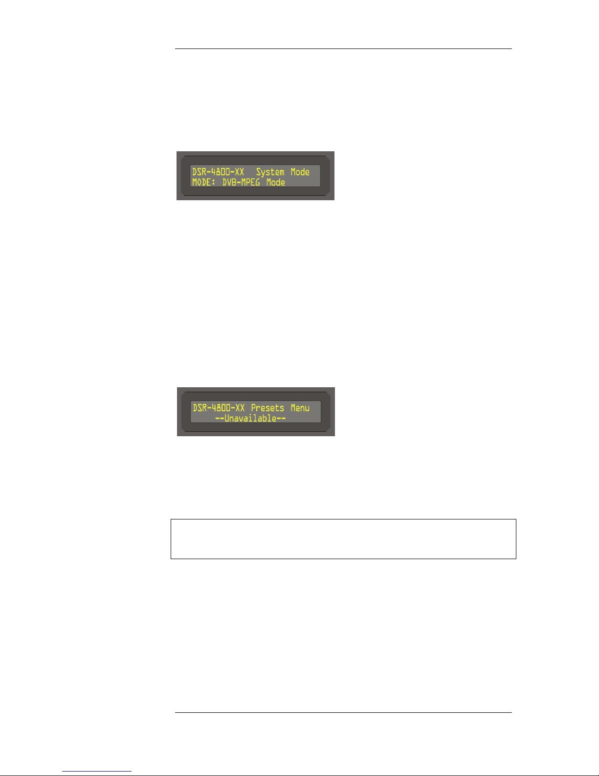
DVB-MPEG Mode:
Display (EXT 2) Menu 3
DVB-MPEG MODE
, When in this mode all DCII virtual channel selection features are
ignored. The receiver’s RF demodulation mode should be
changed to DVB mode. The satellite number and V/H automatic
functions are disabled. All other functions work the same as in
DCII Manual mode. The audio will automatically switch
between Dolby AC3 and Musicam audio signals.
PRESETS MENU:
Display (EXT 1)
, Currently not available.
RF MENU:
NOTE: The RF Menu has multiple functions, which depend on the mode of
operation. The DSR-4800 has three modes of operation, and the function of
each field as related to the mode of operation is shown below.
19 DSR-4800 Operating Manual
Page 28
Front Panel Controls and Menu Display
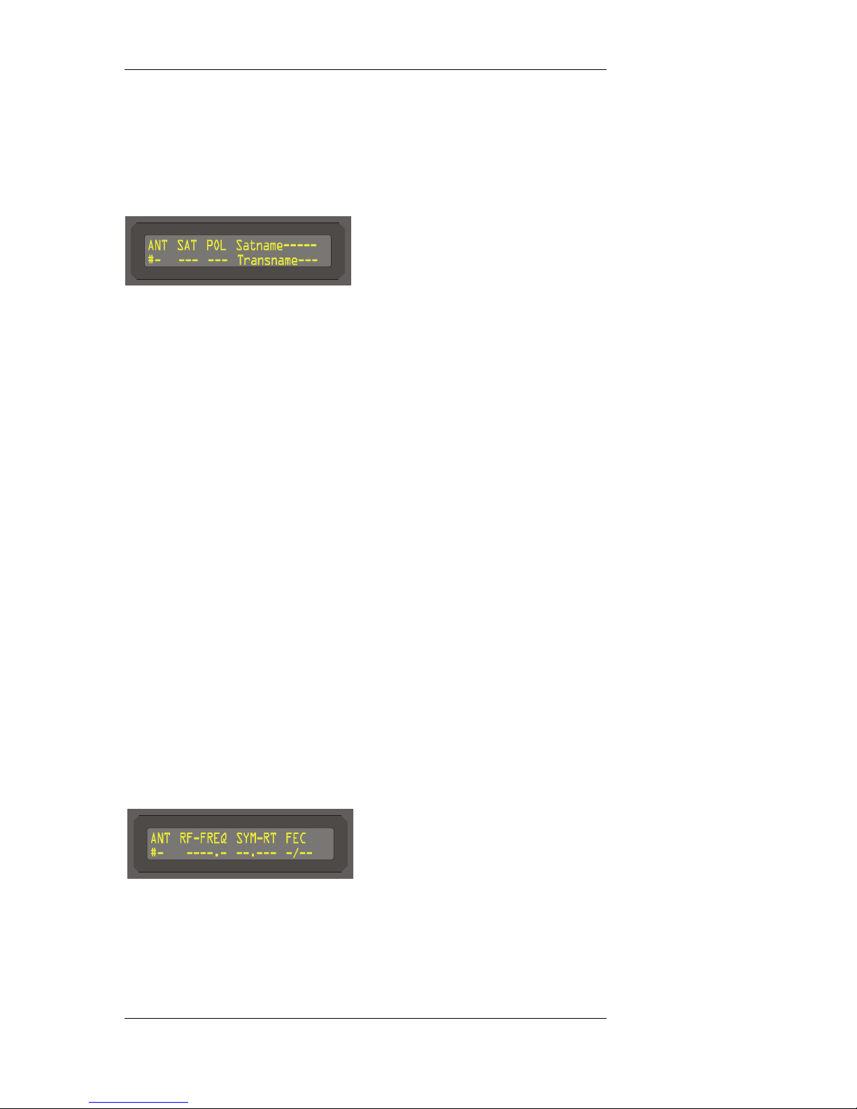
DCII VCT Mode (Read Only):
Display (EXT 1)
ANT
, Displays the current antenna being used.
SAT
, Displays the current satellite ID number assigned to this port.
(For DCII VCT mode operation only.)
POL
, Displays the current polarity configuration of the satellite
attached to the port. (For DCII VCT mode operation only.)
SATNAME
, Contains the current satellite name, twelve (12) characters in
length, identified by the DCII-MSP Satellite Name Table. (For
DCII VCT mode operation only.)
TRANSNAME
, Contains the current transponder name, twelve (12) characters in
length, identified by the DCII-MSP Transponder Name Table.
(For DCII VCT mode operation only.)
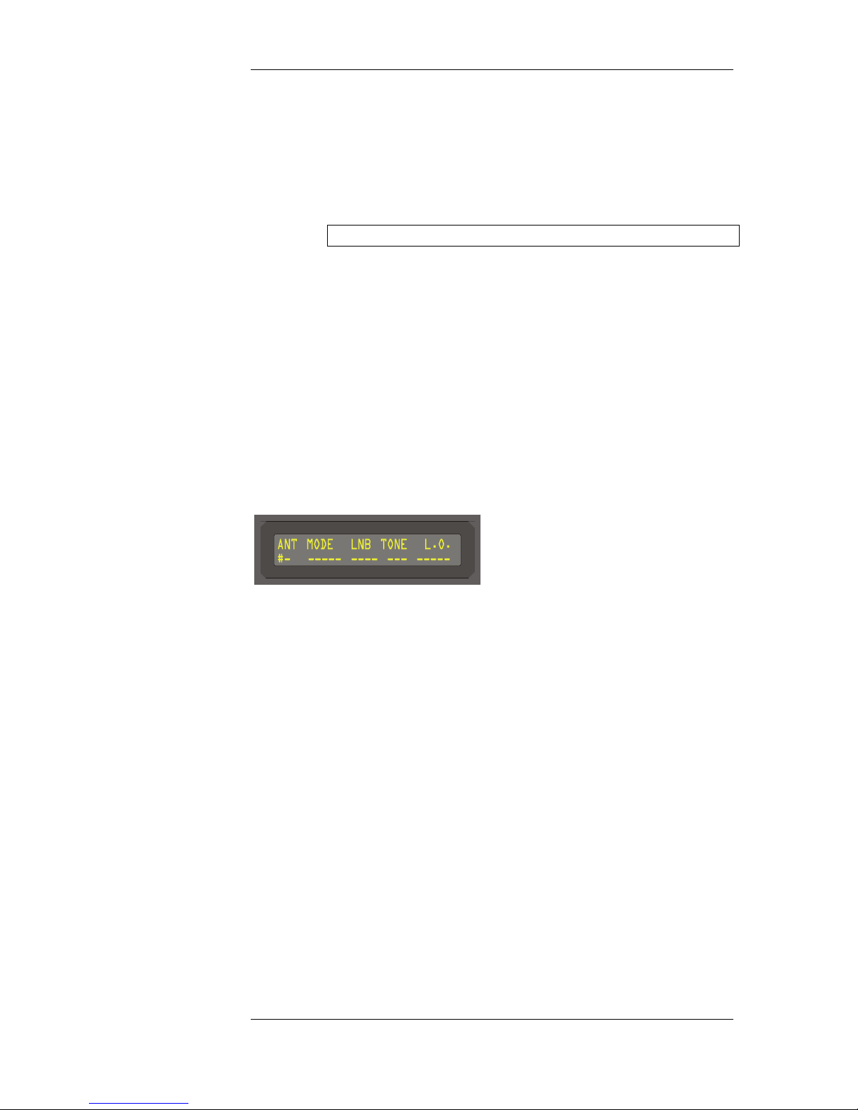
Configuration Mode (Adjustable):
Display (EXT 2)
ANT
, Displays the current antenna being used.
DSR-4800 Operating Manual 20
Page 29
Front Panel Controls and Menu Display
RF-FREQ
, Displays the current RF-frequency defined for the current port.
, This field is in units of MHz and is capable of 125kHz steps.
NOTE: Due to space constraints the display will round up.
SYM-RT
, Displays the current symbol rate defined for the current port.
, This field is in units of Msps and is capable of 1 ksps steps.
FEC
, Displays the current forward error correction (viterbi puncture
rate) of the current port.
DVB Mode:
Display (EXT 3)
ANT
, Displays the current antenna being used.
MODE
, Displays the current modulation mode and modulation type
being used by the current port.
LNB
, Defines the power level sourced by the current port to the LNB
on the antenna.
TONE
, Displays the current setting of the 22kHz tone generation on the
current port.
21 DSR-4800 Operating Manual
L.O.
, Displays the current setting of the local oscillator being used on
the current port.
Page 30
Front Panel Controls and Menu Display
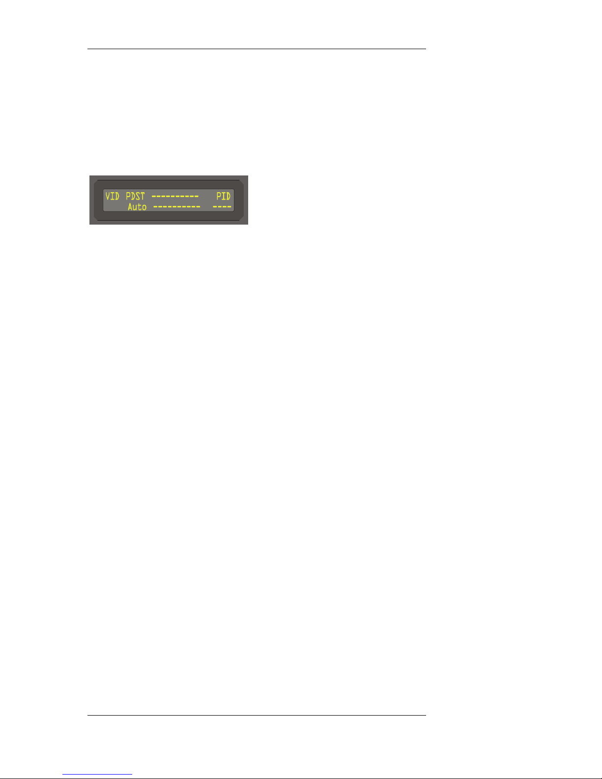
VIDEO MENU:
Display (EXT 1)
VID
, This menu displays the Video parameters.
PDST
, A four (4) character field allowing control of the pedestal setting.
Options are:
, Display Format: The source video format.
ASPECT RATIO
, Aspect ratio of the source video.
VIDEO FORMAT
, Video format of the source video, (i.e., 4:2:2 or 4:2:0).
PID
, The PID carrying the video bit stream.
CONTROL:
LEV
, Not implemented in the DSR-4800.
– Off – override: pedestal off
– On – override: pedestal on
– Auto – pedestal setting determined by GI-MSP messages
DSR-4800 Operating Manual 22
Page 31
Front Panel Controls and Menu Display
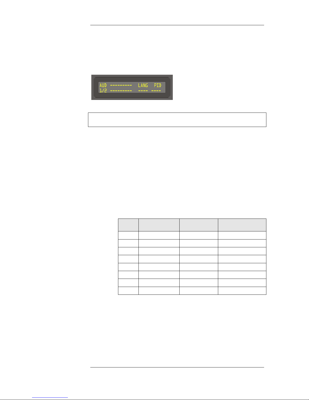
AUDIO MENU:
Display (EXT 1)
NOTE: This menu displays the audio parameters as defined in the Synch Info
and Bit Stream Information fields of the Dolby AC3 audio frame.
AUD
, A three (3) character field that enables the user to display the
audio parameters for the primary (1/2) and secondary (3/4) audio
channels.
AUDIO FORMAT
, A nine (9) character display showing the Dolby AC3 audio
Coding mode according to the following table:
Audio Coding Mode
acmod Audio Coding
Mode
‘000’ 1+1 2 Ch1, Ch2
‘001’ 1/0 1 C
‘010’ 2/0 2 L, R
‘011’ 3/0 3 L, C, R
‘100’ 2/1 3 L, R, S
‘101’ 3/1 4 L, C, R, S
‘110’ 2/2 4 L, R, SL, SR
‘111’ 3/2 5 L, C, R, SL, SR
LANGUAGE CODE
nfchans Channel Array
Ordering
23 DSR-4800 Operating Manual
, A four (4) character display of the language code according to
the following table:
Page 32
Front Panel Controls and Menu Display
Language Code
Language Code
(langcode)
NOTE: If the language code is not available or not supported, the
field will be filled with dashes.
PID
, The PID carrying the encoded audio bitstream.
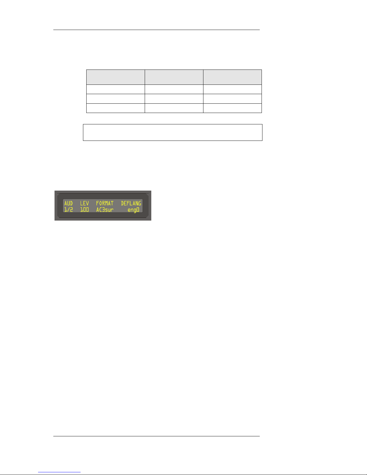
Display (EXT 2)
AUD
, A three (3) character field that enables the user to display the
audio control parameters for the primary (1/2) and secondary
(3/4) audio channels.
Language Display
0x09 English ENG
0x0A Spanish SPA
0x0F French FRE
LEV
, A three (3) character display which enables the user to adjust the
audio output level in increments of full scale. Output is reference
to full scale with 0%-0 dBm, 100%=18 dBm with a 600 ohm
load.
FORMAT
, Allows user to select between a format overrides, (i.e., DUAL,
MONO, STEREO or AC3SUR).
DEFLANG
, Allows user to enter a default language selection for the receiver
to look for when changing virtual channels. If the receiver
cannot find the selected default language, it will pick the
universal language, if available, or the first two defined audio
programs in the list.
DSR-4800 Operating Manual 24
Page 33
Front Panel Controls and Menu Display
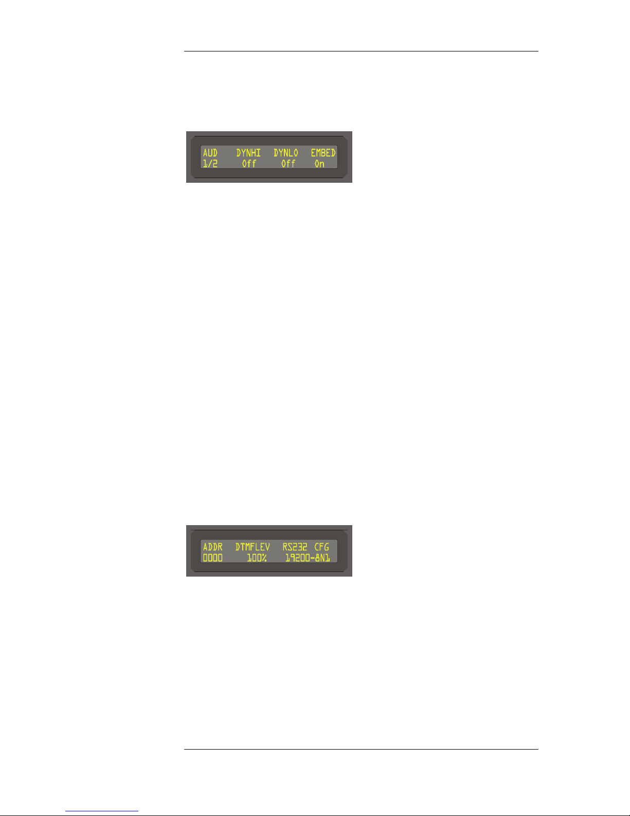
Display (EXT 3)
AUD
, A three (3) character field that enables the user to display the
audio control parameters for the primary (1/2) and secondary
(3/4) audio channels.
DYNHI
, Allows the user to enter dynamic range compression in Off,
Low, Medium or High modes for the high level audio spectrum.
DYNLO
, Allows the user to enter dynamic range compression in Off,
Low, Medium or High modes for the low level audio spectrum.
EMBED
, Allows the user to disable the four channel embedded audio in
the SDI digital output.
REMOTE MENU:
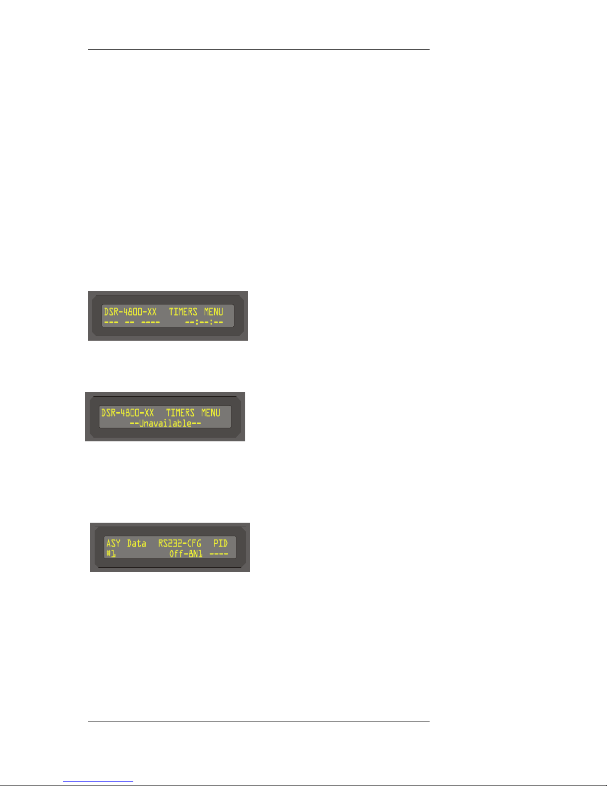
Display (EXT 1)
ADDR
, Displays the current slave address of this unit.
– The value is fully editable with a range from 0x0000-
0xFFFF.
25 DSR-4800 Operating Manual
– Each DSR-4800 unit daisy chained together with EIA485
should have it’s own unique address.
Page 34
Front Panel Controls and Menu Display
DTMFLEV
, Controls the DTMF audio output level (100 is the default setting
for +18 dBm at 600 ohm load.)
RS XXX - CFG
, Displays the currently active communication protocol, (i.e.,
RS232, RS485).
TIMERS MENU:
Display (EXT 1)
Display (EXT 2)
DATA MENU:
Display (EXT 1)
ASYNC DATA
, Displays the Async Data Service information from the selected
virtual channel. This is an automatic function and if no Async
service is available, the RS232 is in OFF condition and the PID
is blank.
DSR-4800 Operating Manual 26
Page 35
Front Panel Controls and Menu Display
Display (EXT 2)
, This menu level is for factory use only.
Display (EXT 3)
, This menu level is for factory use only.
CONFIG MENU:
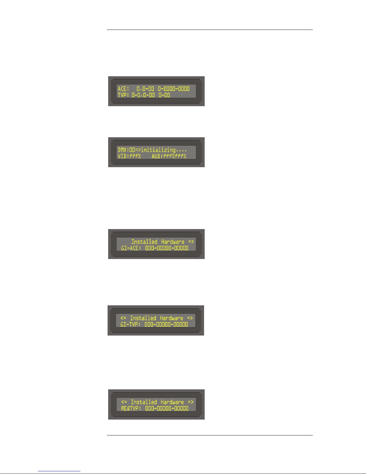
Display (EXT 1) Menu 1
GI-ACE
, Displays the installed GI ACE serial number.
Display (EXT 1) Menu 2
GI-TVP
, Displays the currently installed (or required) GI-TV Pass
module.
Display (EXT 1) Menu 3 REQTVP
27 DSR-4800 Operating Manual
Page 36
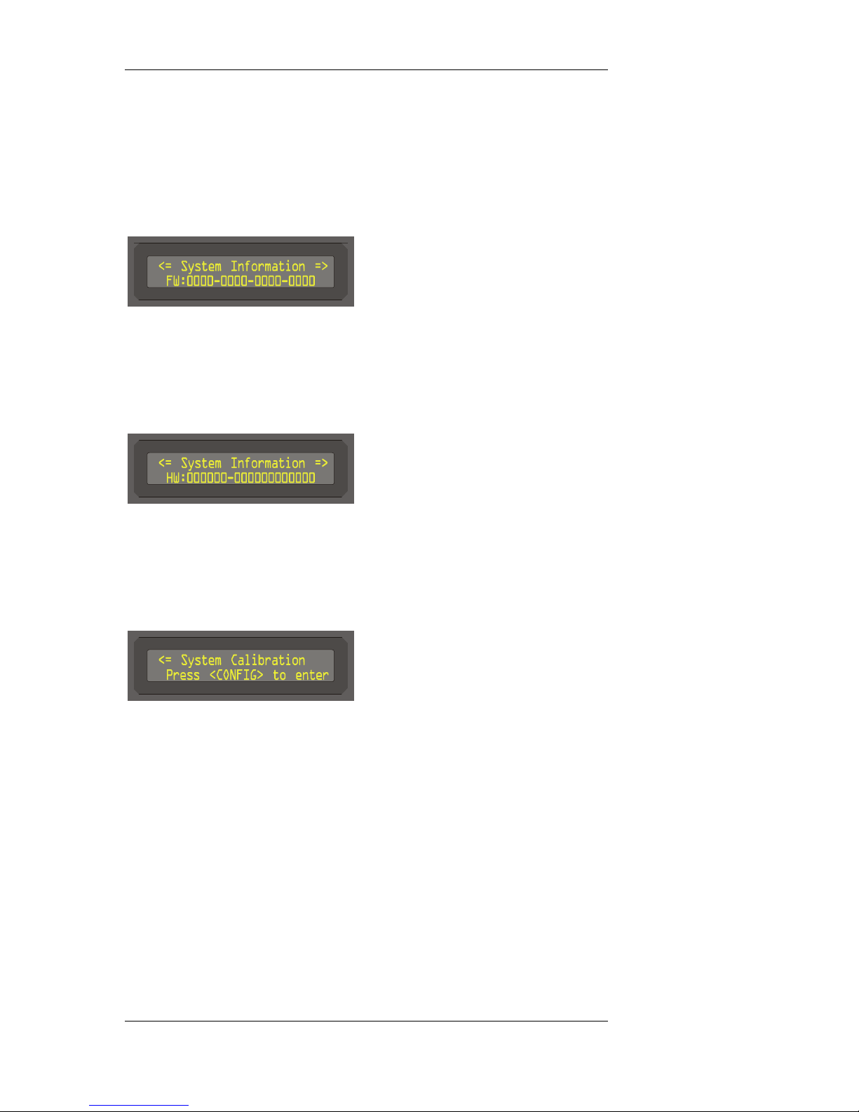
Front Panel Controls and Menu Display
REQTVP
, Displays the required TVP card serial number if required.
Display (EXT 1) Menu 4
FW
, Displays the current firmware version.
(For service personnel use only.)
Display (EXT 1) Menu 5
HW
, Displays the current hardware version.
(For service personnel use only.)
Display (EXT 1) Menu 6
SYSTEM CALIBRATION
, For factory use only.
DSR-4800 Operating Manual 28
Page 37
Front Panel Controls and Menu Display
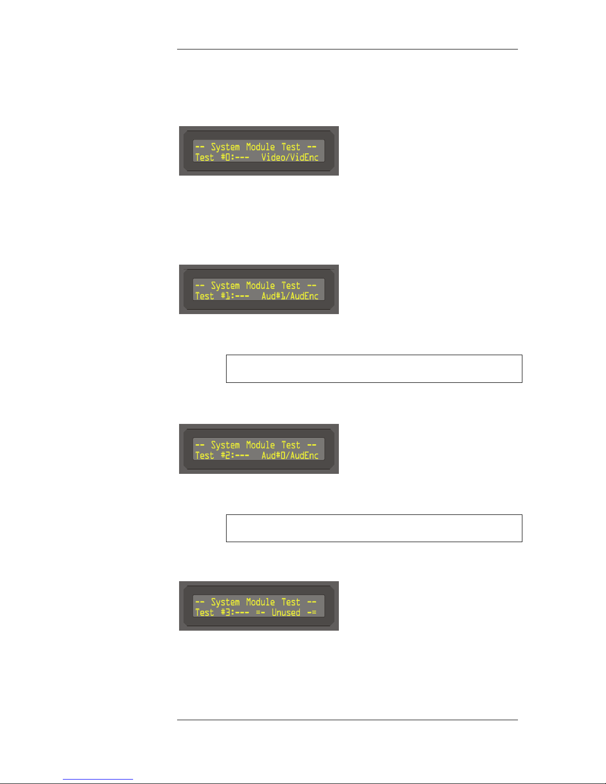
Display (EXT 2) Menu 1, Edit Option 1
, The default video pattern is color bars at 1.0 vp-p. Use the blank
area to turn on/off the color bar pattern. Note this will interrupt
the receiver's current video output until the user turns off the test
signal.
Display (EXT 2) Menu 1, Edit Option 2
, The default audio signal is 1KHz tone +18 dBm. Use the blank
area to turn the tone on/off for primary.
Note this will interrupt the receiver's current audio output until
the user turns off the test signal.
Display (EXT 2) Menu 1, Edit Option 3
, The default audio signal is 1KHz tone +18 dBm. Use the blank
area to turn the tone on/off for secondary.
Note this will interrupt the receiver's current audio output until
the user turns off the test signal.
Display (EXT 2) Menu 1, Edit Option 4
, Currently unused test mode.
29 DSR-4800 Operating Manual
Page 38
Front Panel Controls and Menu Display
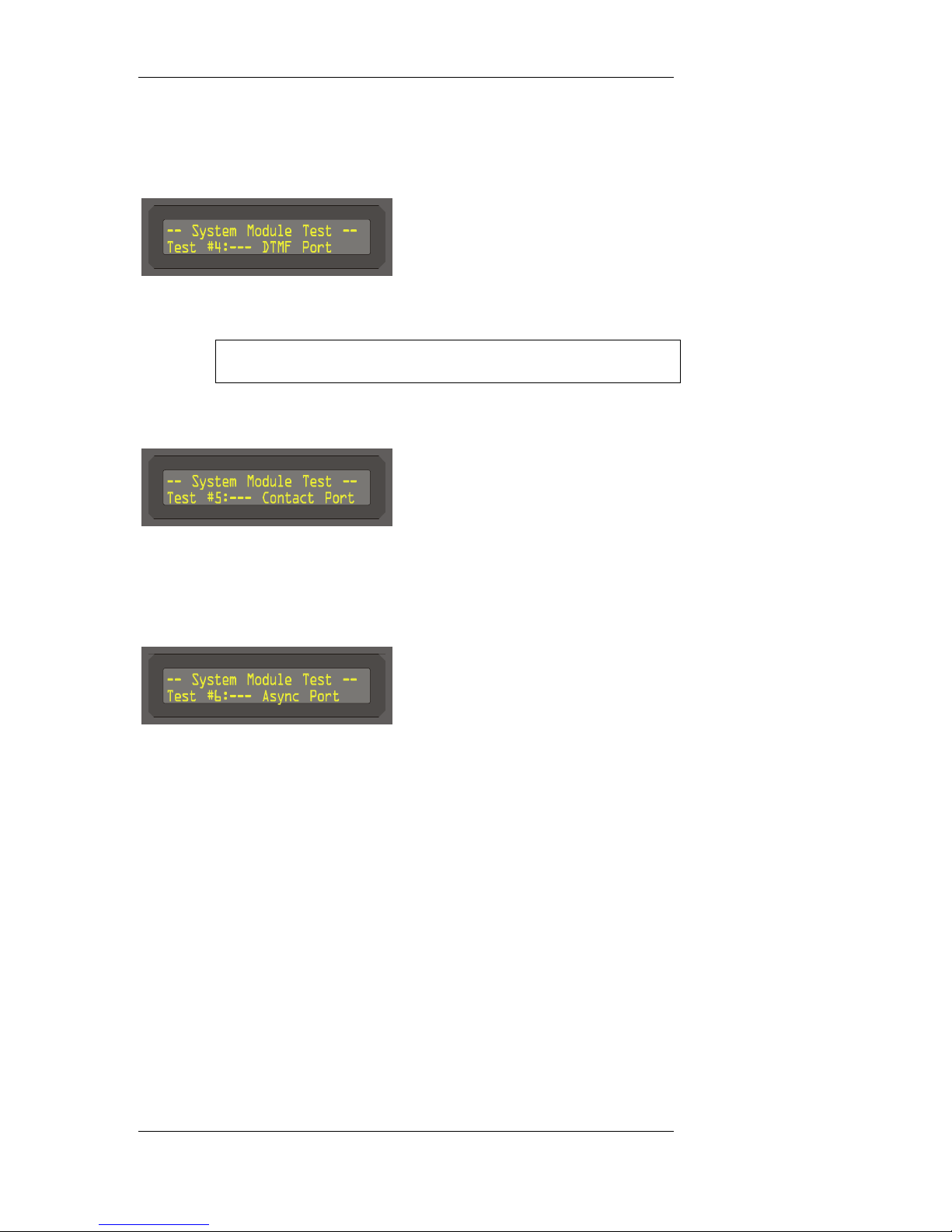
Display (EXT 2) Menu 1, Edit Option 5
, The default audio signal is a multi DTMF tone (12345) at +18
dBm. Use the blank area to turn on/off the tone.
Note this will interrupt the receiver's current audio output until
the user turns off the test signal.
Display (EXT 2) Menu 1, Edit Option 6
, This test will alternate the external two contact closures on and
off, at 1.0 second intervals; when on forces them to close, when
off operates normally.
Display (EXT 2) Menu 1, Edit Option 7
, This menu will be erased.
DSR-4800 Operating Manual 30
Page 39
Front Panel Controls and Menu Display
ALARMS MENU:
Display (EXT 1)
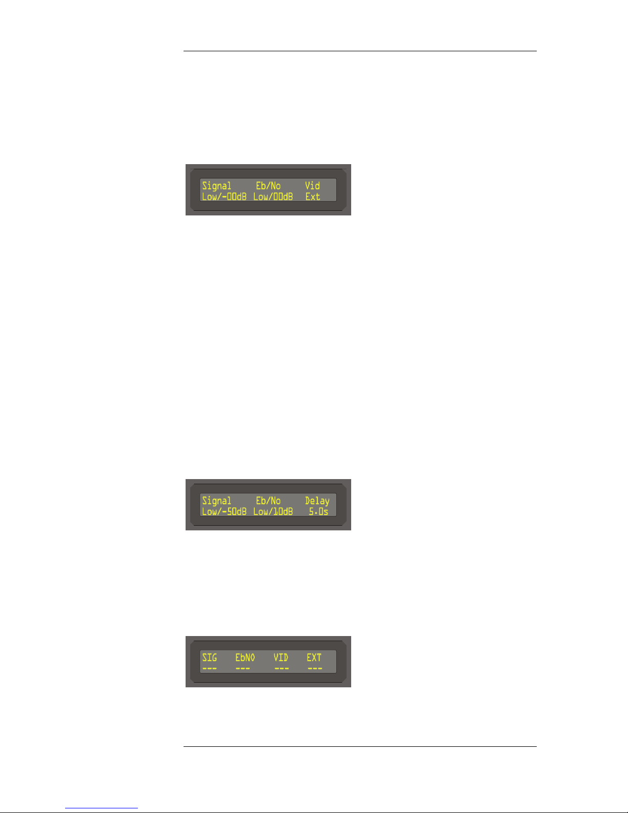
, Displays the current condition of the alarms. Below the Signal
heading is the real-time RF input signal level in -dBm. Next to
the signal level is the alarm threshold. If the signal level is
below -65dBm the meter will read Low. If the Signal is in alarm
condition, brackets will be placed around the word <Signal>.
, Below the Eb/No is the real-time Eb/No Signal reading. Next to
it is the alarm threshold level. If the Eb/No level is below
threshold, the reading will be Low. The alarm threshold can be
set from 3.0 to 20 dB. If the Eb/No is in alarm condition,
brackets will be placed around the word <Eb/No>.
, Vid displays the current video output condition. If the Vid is in
alarm condition, brackets will be placed aroung the word <Vid>.
, Ext displays the current external alarm contact condition. If the
Ext is in alarm condition, brackets will be placed aroung the
word <Ext>.
Display (EXT 2)
, Allows the user the set the threshold levels for Signal and Eb/No.
There is also an alarm delay setting for all alarm conditions. The
setting can be adjusted from 0.0 to 9.9 seconds. This delay is
used so that when changing channels, the alarms are not set
immediately off.
Display (EXT 3)
31 DSR-4800 Operating Manual
, Allows user to turn on/off each of the alarm functions.
Page 40

Front Panel Controls and Menu Display
SAVE MENU:
, There is no menu associated with the Save button. Press when
illuminated to save the current setting.
DSR-4800 Operating Manual 32
Page 41
Rear Panel And Connectors
131415121234567891011(a-d)
16(a-j)
CHAPTER 6
REAR PANEL AND CONNECTORS
REAR PANEL
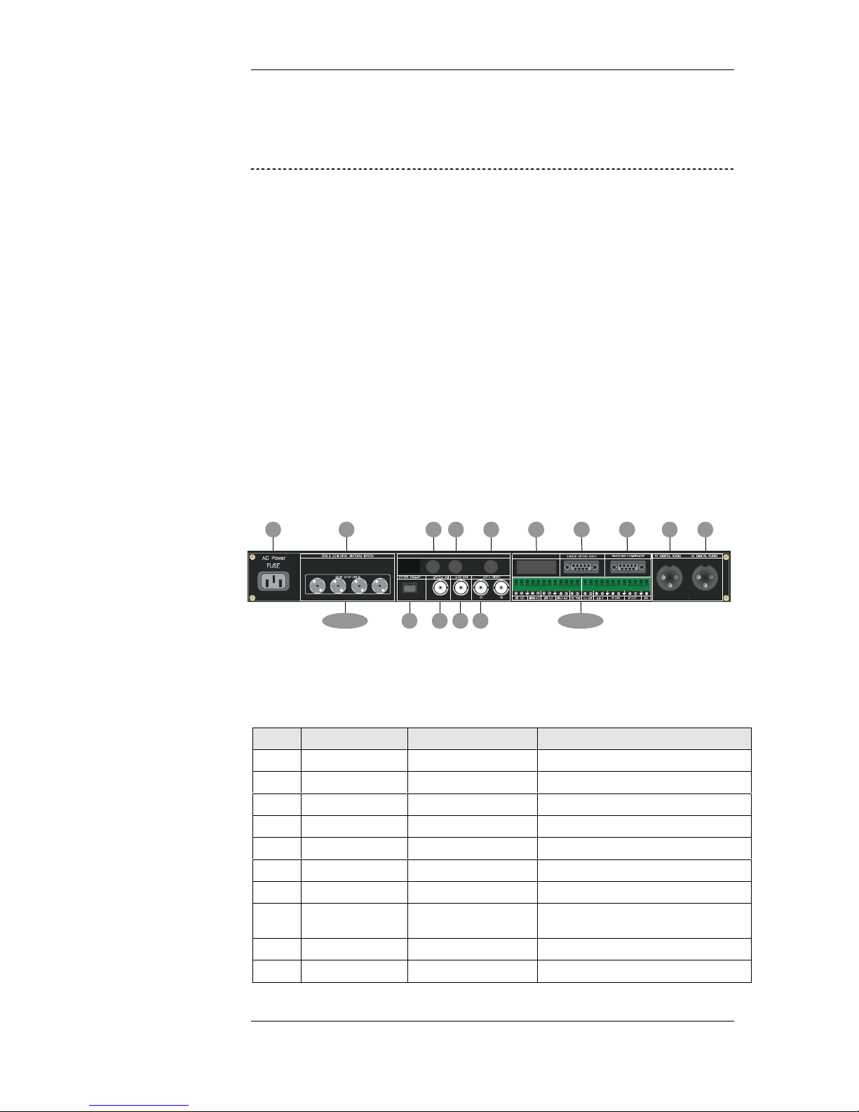
All items in this section pertain to the rear panel of the DSR-4800, which
includes AC Power Input; RS 232 Interfaces; #1 Digital Audio, #2 Digital
Audio, L-band RF Input, ASI Transport, #1 Baseband Video, #1 Baseband
Video and Terminal Strip.
Figure 5-2
The Rear Panel
#3 #4#1 #2
Table 5-2
The Rear Panel
# Control Type Description
1 AC Power Input Line Power Connector Primary 110V~, 50/60 Hz , 70 W
2 Bar Code/Label Serial Number
3 BNC Type Connector 4810 Video Sync Option
4 BNC Type Connector 4810 Video Sync Option
5 BNC Type Connector 4810 Video Sync Option
6 Not Used
7 RS 232 Async Data dB 9 Pin Type Connector 9.6–19.2kbps
8 RS 232/485 Log
Remote dB 9 Pin Type Connector
9 #1 Digital Audio XLR Type Connector AES/EBU Digital Audio Output
10 #2 Digital Audio XLR Type Connector AES/EBU Digital Audio Output
Log Remote (Provides Remote Control Interface
Access)
33 DSR-4800 Operating Manual
Page 42

Rear Panel and Connectors
11 L-band RF Input Group DVB & DC-II QPSK Antenna Inputs with +20V
11a #1 RF Input F Type Connector 950 to 2150 MHz L-band Input
11b #2 RF Input F Type Connector 950 to 2150 MHz L-band Input
11c #3 RF Input F Type Connector 950 to 2150 MHz L-band Input
11d #4 RF Input F Type Connector 950 to 2150 MHz L-band Input
12 Ethernet RJ-45 Ethernet 10Base-T
13 ASI Output BNC Type Connector 210 Mbit DVB Format
14 4:2:2 SDI BNC Type Connector SMPTE 259 Digital Video Output
15 #1 Baseband Video BNC Type Connector Baseband Video Output
16 Terminal Strip Phoenix Connector
16a #1/L AUD 600 ohm Balanced Audio Output/Left
16b #2/RM AUD 600 ohm Balanced Audio Output/Right/Mono
16c #3/L AUD 600 ohm Balanced Audio Output/Left
16d #4/RM AUD 600 ohm Balanced Audio Output/Right/Mono
16e CUE TONE DTMF Commercial Tone Output
16f ALM OUT
16g ALM IN
16h #1 CONT Dry Contact Closure
16I #2 CONT Dry Contact Closure
16j AGC AGC Voltage Output Range
DC LNBC voltage provided on the selected input
port.
DSR-4800 Operating Manual 34
Page 43
Rear Panel And Connectors
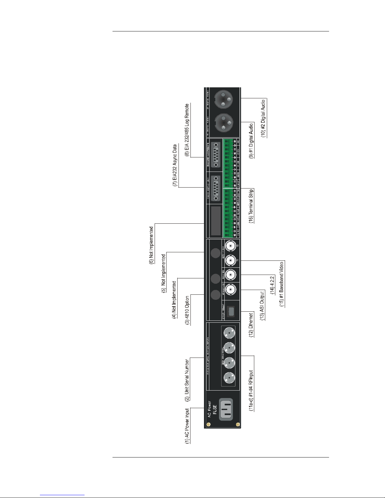
Figure 6-2
The Rear Panel
35 DSR-4800 Operating Manual
#4
#3
#2
#1
Page 44

Rear Panel and Connectors
#3#
4
CONNECTING THE CONNECTORS
Signal connections are made via the rear panel. Refer to Figure 5-2 for a
description of the rear panel connections.
AC POWER INPUT
Line Power Connector
Make sure there is a supply socket located near the equipment so that it is
easily accessible.
RS 232 ASYNC DATA
dB 9 Pin Type Connector
9.6–19.2 Kbps Async Data Port
RS 232/485 LOG/REMOTE
dB 9 Pin Type Connector
DSR units provide diagnostic and remote control compatibility via this RS
compliant interface.
#1 & #2 DIGITAL AUDIO
XLR Type Connectors
AES/EBU compliant digital audio interfaces. SMPTE #272.
#1 - #4 RF INPUT
#1
#2
F Type Connectors
950–2150MHz RF Input interface. The DSR unit, by virtue of the virtual
channel table, can automatically select from any transponder input via these
four satellite inputs.
DSR-4800 Operating Manual 36
Page 45
Rear Panel And Connectors
NOTE: DC voltage may be present on the active port. Verify setup
procedures on RF Menu (Ext 3), page 21 prior to connecting external
equipment.
ETHERNET
RJ-45
Standard 10Base-T Ethernet interface.
ASI OUTPUT
BNC Type Connectors
270 Mbit DVB asynchronous interface.
Outputs the entire transport stream with the selected program decrypted.
4:2:2 SDI
BNC Type Connectors
SMPTE 259 digital video output with embedded audio.
TERMINAL STRIP
Phoenix Connectors
Provides access to all baseband video. Summary alarms and dry contact
closures. Also has real-time AGC voltage output.
37 DSR-4800 Operating Manual
Page 46

Language Abbreviations
CHAPTER 7
LANGUAGE ABBREVIATIONS
LANGUAGE ABBREVIATION LANGUAGE ABBREVIATION
Arabic ara Japanese jpn
Armenian arm Javaneses jav
Balinese ban Kashmiri kas
Basque baq Korean kor
Batak (Indonesian) btk Kurdish kur
Bengali ben Latin lat
Bhojpuri bho Malay may
Bihari bih Malayam mal
Bulgarian bul Mandar mdr
Burmese bur Marathi mar
Catalan cat Miscellaneous Languages mis
Chinese chi Mongolian mon
Croatian scr Nepali nep
Cue (Tones) cue Norwegian nor
Czech cze Otomian Languages oto
Danish dan Pahlavi pal
Dutch dut Panjabi pan
Egyptian egy Persian per
English eng Philippine (Other) phi
Esperanto epo Polish pol
Faroese fao Portuguese por
Finnish fin Rajasthani raj
French fre Romanian rum
German ger Russian rus
Greek gre Samoan smo
Gujarati guj Scots sco
Hebrew heb Sindhi cnd
Himachali him Spanish spa
Hindi hin Swahili swa
Hiri Motu hmo Swedish swe
Hungarian hun Tagalog tgl
Icelandic ice Tahitian tah
Indonesian ind Tamil tam
Interlingua (International Auxiliary Thai tha
Language Assn.) ina Turkish tur
Irinian Ira Urdu urd
Irish iri Vietnamese vie
Italian ita Welsh wel
DSR-4800 Operating Manual 38
Page 47

Language Abbreviations
CHAPTER 8
PRODUCT SUPPORT & EQUIPMENT RETURNS
IF YOU NEED HELP
If you need assistance while working with the DSR-4800, DSR-4810 or
DSR-4850, call the General Instrument Technical Assistance Center at
1-800-457-1210, 24 hours a day, 7 days a week.
REPAIRING PROCEDURES:
GI has established streamlined processes to ensure rapid return of product if
repair is required.
As a system operator, you must return the unit to General Instrument for
repair.
After speaking with a technician at the T.A.C, if a RMA is deemed necessary
a Case Number will be generated and forwarded to the repair facility.
The repair facility will issue the RMA to return the product to be worked on.
When shipping product for repair, please follow these steps:
1. Pack the unit securely
2. Enclose a note describing the problem
3. Enclose a copy of the invoice showing warranty status
4. Make sure the Case Number from the TAC is on the outside of the box.
Ship the unit prepaid to the repair facility indicated by the repair center.
(Undetermined at this time.)
Page 48

WARRANTY
LIMITED WARRANTY
Commercial Integrated Receiver Decoder
General Instrument Corporation (“General Instrument”) hereby warrants for the benefit of
purchasers of Commercial Integrated Receiver Decoders (“IRD”) furnished herewith (“You”),
that such IRDs shall be free from defects in material and workmanship for a period of twelve (12)
months commencing from date of original purchase for commercial use. General Instrument’s
obligation under this limited warranty shall be limited to repairing, or at its option, replacing any
such defective IRD, which shall be returned to General Instrument. A replacement unit need not
be new.
This warranty shall apply only to IRDs which, after regular installation and normal usage, are
found by General Instrument, in its reasonable determination, to have been defective or
nonconforming within the warranty period.
The IRD warranty set forth above shall be void: (i) if any IRD label, marking or serial number
has been defaced or removed; (ii) if any IRD has been abused, misused, improperly installed,
damaged in shipment or by accident, negligence or unusual hazard; (iii) if any IRD has been
altered, repaired or modified by anyone other than General Instrument without General
Instrument’s prior written approval; or (iv) if any IRD has had its housing opened.
General Instrument shall have no liability to any third person or entity in relation to any warranty
or representation which purports to extend, alter, or modify the limited warranty terms set forth
above. General Instrument shall not be responsible for delays in performance of its obligations
under this limited warranty resulting from events outside its reasonable control
THE LIMITED WARRANTY IS IN LIEU OF ALL OTHER WARRANTIES AS TO
PERFORMANCE OF THE IRD, WHETHER STATUTORY, EXPRESS OR IMPLIED,
INCLUDING WITHOUT LIMITATION ANY IMPLIED WARRANTIES OF
MERCHANTABILITY OR FITNESS FOR A PARTICULAR USE OR PURPOSE. THE SOLE
AND EXCLUSIVE REMEDY FOR ANY BREACH BY GENERAL INSTRUMENT OF THIS
LIMITED WARRANTY SHALL BE FOR GENERAL INSTRUMENT TO MAKE SUCH
REPAIRS AND OR REPLACEMENTS AS ARE NECESSARY TO FULFILL SUCH
WARRANTY. IN NO EVENT SHALL GENERAL INSTRUMENT BE LIABLE FOR ANY
INDIRECT, EXEMPLARY, INCIDENTAL, SPECIAL OR CONSEQUENTIAL DAMAGES,
INCLUDING WITHOUT LIMITATION DAMAGES FOR LOSS OF AUDIO, VIDEO OR
DATA SIGNALS, LOST PROFITS, NON-RECEIPT AND NON-DELIVERY OF
PROGRAMMING, AND INTERRUPTION OF BUSINESS ARISING OUT OF OR IN
CONNECTION WITH THE USE OR PERFORMANCE OF THE IRD WARRANTED
HEREIN, WHETHER BASED UPON BREACH OF WARRANTY, STATUTORY
VIOLATION, NEGLIGENCE, STRICT LIABILITY OR ANY OTHER LEGAL THEORY.
How to Obtain Warranty Service. To obtain warranty service, You must call or write General
Instrument Technical Assistance Center within the applicable warranty period at: General
Page 49

Instrument Corporation, 6450 Sequence Drive, San Diego, CA 92121, 1-800-457-1210. The
Technical Assistance Center is open 7 days a week, 24 hours a day.
When You call or write, explain the problem. Ask whether the IRD should be returned for service
or retained by You for servicing in place. Ask for a Return Material Authorization (RMA)
number and for the address to send the IRD if the IRD is to be returned. If You write, be sure to
include a copy of your sales receipt or other proof of purchase date, a copy of your warranty, your
phone number and return address. If the Technical Assistance Department instructs you to return
the IRD, pack it safely and securely, preferably in the original shipping carton. Put the RMA
number on the outside of the shipping carton. Enclose a letter explaining the problem. Be sure to
include a copy of your sales receipt or other proof of purchase date, a copy of your warranty, and
your phone number and return address. Ship it insured to the authorized service center specified
by General Instrument. All packing, shipping and insurance to return the IRD to General
Instrument must be prepaid by you. General Instrument Corporation shall pay return shipping
charges.
NOTE: If the warranty on your IRD is expired, voided or inapplicable as determined by General
Instrument Corporation in its reasonable discretion, General Instrument will not repair the IRD
until You agree to pay for quoted charges. If You do not agree within 30 days to pay the quoted
charges, the IRD will be returned to You unrepaired. You are responsible for transportation
charges both ways on IRDs, which are not under warranty or on which the warranty has been
voided or is inapplicable.
Page 50

Page 51

 Loading...