

Page 1
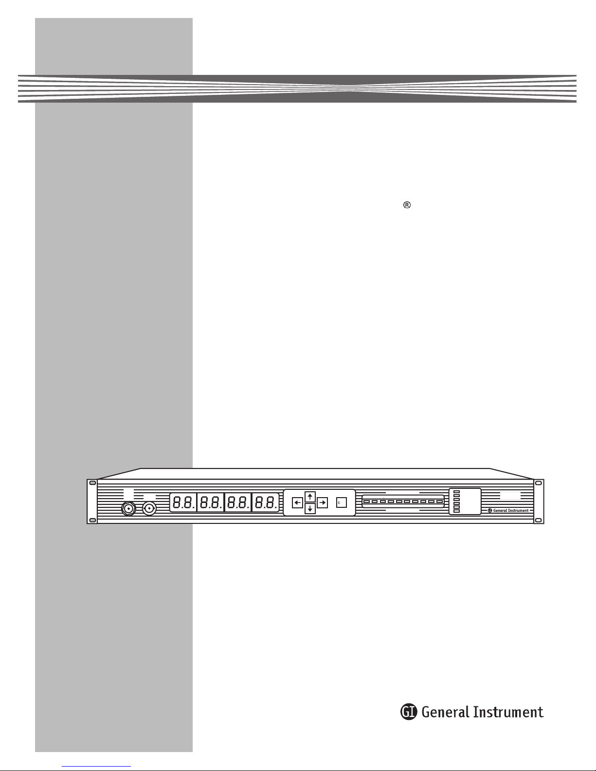
C6M-II
®
Commander 6 Modulator
Installation Manual
TEST
VIDEO
-20dB
OUT
RF
ENT
video modulation (%)
20 80 87.5
20 25 30
5
audio deviation (kHz)
REF OFF
95
VIDEO OFF
VIDEO B
AUX IF
50
PRGM IF
REMOTE
C6M-II
Page 2
Caution
These servicing instructions are for use by qualified personnel only. To reduce the risk of electrical shock, do not perform any servicing other
than that contained in the Installation and Troubleshooting Instructions unless you are qualified to do so. Refer all servicing to qualified service
personnel.
FCC Compliance
This equipment has been tested and found to comply with the limits for a Class A digital device, pursuant to Part 15 of the FCC Rules. These
limits are designed to provide reasonable protection against harmful interference when the equipment is operated in a commercial environment.
This equipment generates, uses, and can radiate radio frequency energy and, if not installed and used in accordance with the Installation Manual,
may cause harmful interference to radio communications. Operation of this equipment in a residential area is likely to cause harmful interference
in which case the user will be required to correct the interference at his own expense. Any changes or modifications not expressly approved by
General Instrument could void the user’s authority to operate this equipment under the rules and regulations of the FCC.
Canadian Compliance
This Class A digital apparatus meets all requirements of the Canadian Interference-Causing Equipment Regulations.
Cet appareil numérique de la classe A respects toutes les exigences du Règlement sur le matériel brouilleur du Canada.
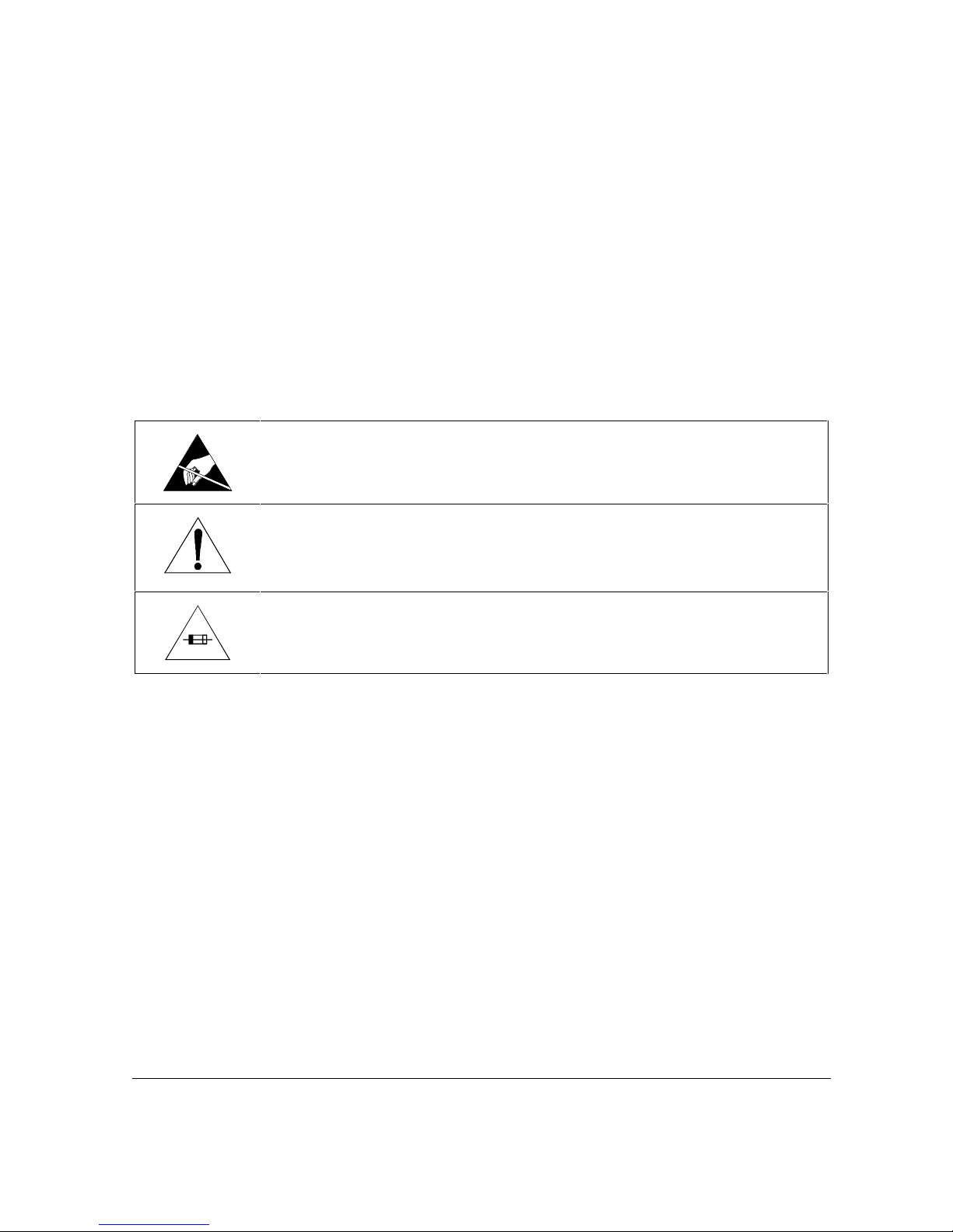
Special Symbols That Might Appear on the Equipment
The symbol shown on the left, a reaching hand in a triangle with a slash through it, is intended to alert the user and
service personnel of the possibility of equipment damage or degradation of performance due to Electrostatic
Discharge (ESD) event.
The exclamation point, within an equilateral triangle, is intended to alert the user to the presence of important
installation, servicing, and operating instructions in the documents accompanying the equipment.
For continued protection against fire, replace all fuses only with fuses having the same electrical ratings marked at
the location of the fuse.
Copyright © 1997 by General Instrument Corporation.
All rights reserved.
No part of this publication may be reproduced in any form or by any means or used to make any derivative work (such as translation,
transformation or adaptation) without written permission from General Instrument.
General Instrument reserves the right to revise this publication and to make changes in content from time to time without obligation on the part of
General Instrument to provide notification of such revision or change.
General Instrument provides this guide without warranty of any kind, either implied or expressed, including, but not limited, to the implied
warranties of merchantability and fitness for a particular purpose. General Instrument may make improvements or changes in the product(s)
described in this manual at any time.
Commander 6 is a registered trademark of General Instrument Corporation.
Page 3

Contents
Section 1 Introduction
Using This Manual ...................................................................................................... 1-2
Related Documentation .............................................................................................. 1-2
Document Conventions .............................................................................................. 1-2
If You Need Help .......................................................................................................... 1-3
Calling for Repairs ...................................................................................................... 1-3
Section 2 Overview
Options ........................................................................................................................ 2-1
C6M-II-MOB Kit ...................................................................................................... 2-2
C6-DC ..................................................................................................................... 2-2
C6-RC-II Kit ............................................................................................................ 2-2
C6M-II-SE Kit .......................................................................................................... 2-2
Model Conventions ..................................................................................................... 2-3
Front Panel Controls and Displays ............................................................................ 2-3
Rear Panel Connectors ............................................................................................... 2-5
The Menu System ........................................................................................................ 2-8
Using the Menus ..................................................................................................... 2-9
Changing a Menu Item ............................................................................................ 2-9
Main Menu .............................................................................................................. 2-10
Option Menu ........................................................................................................... 2-11
Video Menu ............................................................................................................. 2-13
Audio Menu ............................................................................................................. 2-13
Remote Menu ......................................................................................................... 2-14
Warning Messages ...................................................................................................... 2-15
Section 3 Installation
Before You Begin ........................................................................................................ 3-1
Mounting the Modulator ............................................................................................. 3-1
Checking the Operation .............................................................................................. 3-2
Switching Capabilities ................................................................................................ 3-3
Without the MOB Option Board ............................................................................... 3-3
Page 4

ii Contents
With the MOB Option Board .................................................................................... 3-3
Automatic Gain Control ............................................................................................... 3-4
IF AGC .................................................................................................................... 3-4
Baseband AGC (Optional) ....................................................................................... 3-4
Audio Parameters ........................................................................................................ 3-5
Audio Impedance ..................................................................................................... 3-5
Audio Level .............................................................................................................. 3-5
Stereo Encoder (Optional) ....................................................................................... 3-5
Selecting the RF Channel Frequency Plan ................................................................. 3-5
Typical Interconnections ............................................................................................. 3-6
Basic Video and Audio Interfacing ............................................................................ 3-6
Satellite Link Connection .......................................................................................... 3-7
Satellite Link Connection with C6M-II-SE ................................................................. 3-8
Video Scrambling ..................................................................................................... 3-9
CW Output .............................................................................................................. 3-10
Stereo IF Interfacing ................................................................................................ 3-11
Composite Baseband Interfacing ............................................................................. 3-12
CMTS / MVP II / C6M-II Connections ...................................................................... 3-13
C6R-VCII / CMTS / MVP II / C6M-II Connections ..................................................... 3-14
Section 4 System Block Diagrams
Video to IF Modulation System ................................................................................... 4-1
Audio to IF Modulation System .................................................................................. 4-2
IF Switching and AGC System .................................................................................... 4-4
IF to Channel Converter System ................................................................................. 4-5
Appendix A Specifications
RF Output ..................................................................................................................... A-1
IF ................................................................................................................................... A-1
Video ............................................................................................................................ A-1
Audio ............................................................................................................................ A-2
General ......................................................................................................................... A-2
Appendix B Frequency Plan
Appendix C Changing a Menu Item
Appendix D Signal Priority Chart
Page 5

Contents iii
Appendix E Application Notes
C6-LPF600 ................................................................................................................... E-1
Summary ................................................................................................................ E-1
Discussion .............................................................................................................. E-1
Specifications .......................................................................................................... E-2
Figures
Figure 1-1 Front and rear views of the C6M-II .............................................................. 1-1
Figure 2-1 C6M-II front panel ....................................................................................... 2-3
Figure 2-2 C6M-II rear panel with options installed ....................................................... 2-5
Figure 2-3 Menu relationships ...................................................................................... 2-8
Figure 3-1 Rack mounting ............................................................................................ 3-2
Figure 3-2 Operational check connections .................................................................... 3-3
Figure 3-3 Basic video/audio interfacing ....................................................................... 3-6
Figure 3-4 Satellite link connection ............................................................................... 3-7
Figure 3-5 Satellite link connection with stereo encoder ................................................ 3-8
Figure 3-6 MVP II / C6M-II IF interfacing ...................................................................... 3-9
Figure 3-7 MVP II / C6M-II interfacing using the CW output .......................................... 3-10
Figure 3-8 C6M-II / CMTS IF interfacing ....................................................................... 3-11
Figure 3-9 External composite baseband connection .................................................... 3-12
Figure 3-10 C6M-II / MVP II / CMTS interfacing ............................................................. 3-13
Figure 3-11 C6R-VCII / CMTS / MVP II / C6M-II connections ......................................... 3-14
Figure 4-1 Video to IF modulation system .................................................................... 4-1
Figure 4-2 Audio to IF modulation system .................................................................... 4-2
Figure 4-3 IF switching and AGC system ..................................................................... 4-4
Figure 4-4 IF to channel converter system ................................................................... 4-5
Figure E-1 Typical installations of C6-LPF600 .............................................................. E-1
Tables
Table 2-1 Required revision levels .............................................................................. 2-1
Table 2-2 Description of controls and displays ............................................................. 2-3
Table 2-3 Description of rear panel connections .......................................................... 2-6
Table 2-4 Description of Main menu items .................................................................. 2-10
Table 2-5 Description of Option menu items ................................................................ 2-11
Table 2-6 Description of Video menu items ................................................................. 2-13
Table 2-7 Description of Audio menu items ................................................................. 2-13
Table 2-8 Description of Remote menu items .............................................................. 2-14
Table 2-9 Description of flashing messages ................................................................ 2-15
Page 6
Section 1
Introduction
The C6M-II is a state-of-the-art television signal modulator for the most demanding CATV
applications. The system is packaged in a space saving 1.75-inch high rack-mounted housing
and uses efficient switching power supply regulators to minimize power consumption and heat.
Features of the C6M-II include:
n
1 GHz tuning capability
n
Frequency selection in 12.5 kHz steps or channel map
n
Automatic source signal switching
n
Front panel user-friendly interface keypad
n
Easy to read LED display for system operational maintenance
n
Remote monitoring and control option
n
BTSC integrated stereo encoder option
n
dc power option
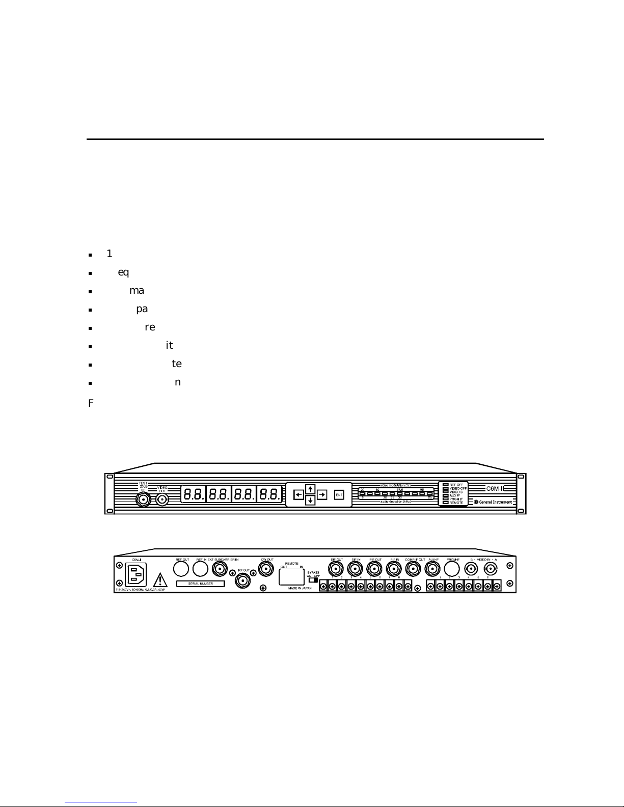
Front and rear views of the C6M-II are shown below without any options.
Figure 1-1
Front and rear views of the C6M-II
C6M-II Installation Manual
Page 7

1-2 Introduction
Using This Manual
This manual includes information and instructions required to install and operate the C6M-II.
Section 1
Section 2
Section 3
Section 4
Appendix A
Appendix B
Appendix C
Appendix D
Appendix E
Introduction
helpline number and information about repair.
Overview
describes the rear panel connectors, and explains the menu system.
Installation
System Block Diagrams
Specifications
Frequency Plan
Changing a Menu Item
Signal Priority Chart
Application Notes
or equivalent filter.
provides a brief description of the C6M-II, related documentation, the
describes the C6M-II, identifies the front panel displays and controls,
provides instructions on how to install and operate the C6M-II.
describes functions of the unit with block diagrams.
provides the technical specifications for the C6M-II.
lists the Frequency Plan.
illustrates how to change a menu item.
provides the priority chart for IF.
provides instructions for installing the C6-LPF600 (928-363-000)
Related Documentation
The following documents describe equipment which can be used with the C6M-II:
n
Modulating Video Processor Model MVP-II Installation Manual
n
Satellite Receiver/Decoder Model C6R-VCII Installation Manual
n
Stereo Encoder Model CMTS Installation Manual
Although these documents provide information that may be of interest to you, they are not
necessary to install or operate the C6M-II modulator.
Document Conventions
Before you begin using the C6M-II, familiarize yourself with the stylistic conventions used in
this manual:
SMALL CAPS Denotes silk screening on the equipment, typically representing front and rear-panel
controls, I/O connections and indicators (LEDs).
* (asterisk)
Indicates that there are several versions of the same model number and the information
applies to all models. When the information applies to a specific model, the complete
model number is given.
C6M-II Installation Manual
Page 8

Introduction 1-3
If You Need Help
If you need assistance while working with the C6M-II, call the General Instrument Technical
Response Center at 1-888-GEN-INST (1-888-436-4678). The Technical Response Center is
open from 8:00 a.m. to 9:00 p.m. Eastern Time, Monday through Friday. When the Technical
Response Center is closed, emergency service only is available on a call-back basis.
When contacting the Technical Response Center from outside the United States, please use our
main switchboard number, 1-215-674-4800, extension 4200.
Calling for Repairs
If repair is necessary, call the General Instrument Repair Facility at 1-800-227-0450 for a
Return for Service Authorization (RSA) number before sending the unit. The RSA number
must be prominently displayed on all equipment cartons. The Repair Facility is open from
8:00 a.m. to 5:00 p.m. Central Time, Monday through Friday.
If calling from outside the United States, dial your appropriate international access code, then
dial 52-891-40739, to contact the Repair Facility.
When shipping equipment for repair, follow these steps:
Pack the unit securely.
Enclose a note describing the exact problem.
Enclose a copy of the invoice that verifies the warranty status.
Ship the unit PRE-PAID to the following address:
GI Communications
2009 McKenzie Road
Suite 102
Carrollton, TX 75006
Attn: RSA #___________
C6M-II Installation Manual
Page 9

Section 2
Overview
The C6M-II is a frequency agile modulator offering an output frequency range from 50 MHz to
1 GHz. All standard, HRC, IRC, and EIA frequencies are available either by keying in the
frequency or using the convenient channel maps.
The C6M-II provides local control by using a front panel user interface. This interface is a
menu system that provides easy access to operating parameters that are microprocessor
controlled for precision, accuracy, stability, and reliability.
Upon frequency or channel selection, the microprocessor automatically engages internal
bandpass filters, ensuring that a combined carrier-to-noise (c/n) ratio of greater than 60 dB is
always maintained with no external filtering required. The c/n performance is guaranteed in
multi-channel combined systems up to 149 channels with a typical performance of 63 dB c/n,
normalized to 4 MHz.
The precision frequency stability of the C6M-II meets the band frequency accuracy
requirements for the FCC. The FCC mandated frequency offsets of +12.5 kHz and +25 kHz are
generated automatically. The C6M-II also exceeds all FCC RF and baseband signal
performance requirements.
Options
The options available for the C6M-II are:
n
Modulator Option Board, model C6M-II-MOB Kit
n
DC Power Option Board, model C6-DC
n
Remote Control Option Board, model C6-RC-II Kit
n
Stereo Encoder Option Board, model C6M-II-SE Kit
The C6M-II must have a minimum firmware revision to install the options. The following table
provides the required revision level.
Table 2-1
Required revision levels
Option C6M-II Firmware Revision
C6M-II-MOB 2.0 or higher
C6-RC-II 1.0 or higher
C6M-II-SE 2.0 or higher
The firmware revision can be found using the Option menu. If the revision in not correct,
please contact General Instrument Technical Response Center for assistance.
C6M-II Installation Manual
Page 10

2-2 Overview
C6M-II-MOB Kit
The C6M-II-MOB accessory module provides baseband audio and video switching, audio and
video AGC, a 4.5 MHz audio subcarrier input, and switched IF input capabilities. The video
switching system includes video A signal sensing to allow automatic switching to video B input
when the video A signal is absent. The audio A and audio B input selection is controlled by the
same circuitry as the video switch section, ensuring the audio input switching follows the video
selection automatically. A rear panel connection allows external control of the input source
switching.
Defeatable video and audio AGC is for applications involving baseband signal levels. Preset
modulation levels are maintained despite fluctuations in the audio/video input levels from the
source or resulting from switching between baseband sources.
An additional IF signal input labeled PROGRAM is identical to the AUX IF switching except
that it has a lower switching priority. The PRGM IF switch is used for program switching or
automatic program replacement when video A and/or video B are absent.
The MOB accessory also accepts the external 4.5 MHz input. The 4.5 MHz input is for audio
interfacing to the output of a stereo encoder, satellite receivers, or demodulator.
C6-DC
The dc power input option accepts a dc input in the range of −20 to −60 Vdc. This option, which
includes a dc-to-dc converter and a rear panel dc inlet, replaces the standard ac power input.
This option is only available from the factory.
C6-RC-II Kit
The C6-RC-II accessory module allows the modulator to be remotely control via a personal
computer. All front panel controls, operating parameters, and adjustments can be monitored
and changed from a remote location. This kit includes a remote control communications board
with an RS-485 type interface using RJ-12 connectors.
C6M-II-SE Kit
The C6M-II-SE is a stereo encoder option for generating stereo sound. It encodes baseband
audio based on BTSC standards, and employs dbx-TV noise reduction circuitry to ensure a
quality signal. This option does not have Second Audio Program (SAP). For SAP applications,
the CMTS should be used.
C6M-II Installation Manual
Page 11
Overview 2-3
Model Conventions
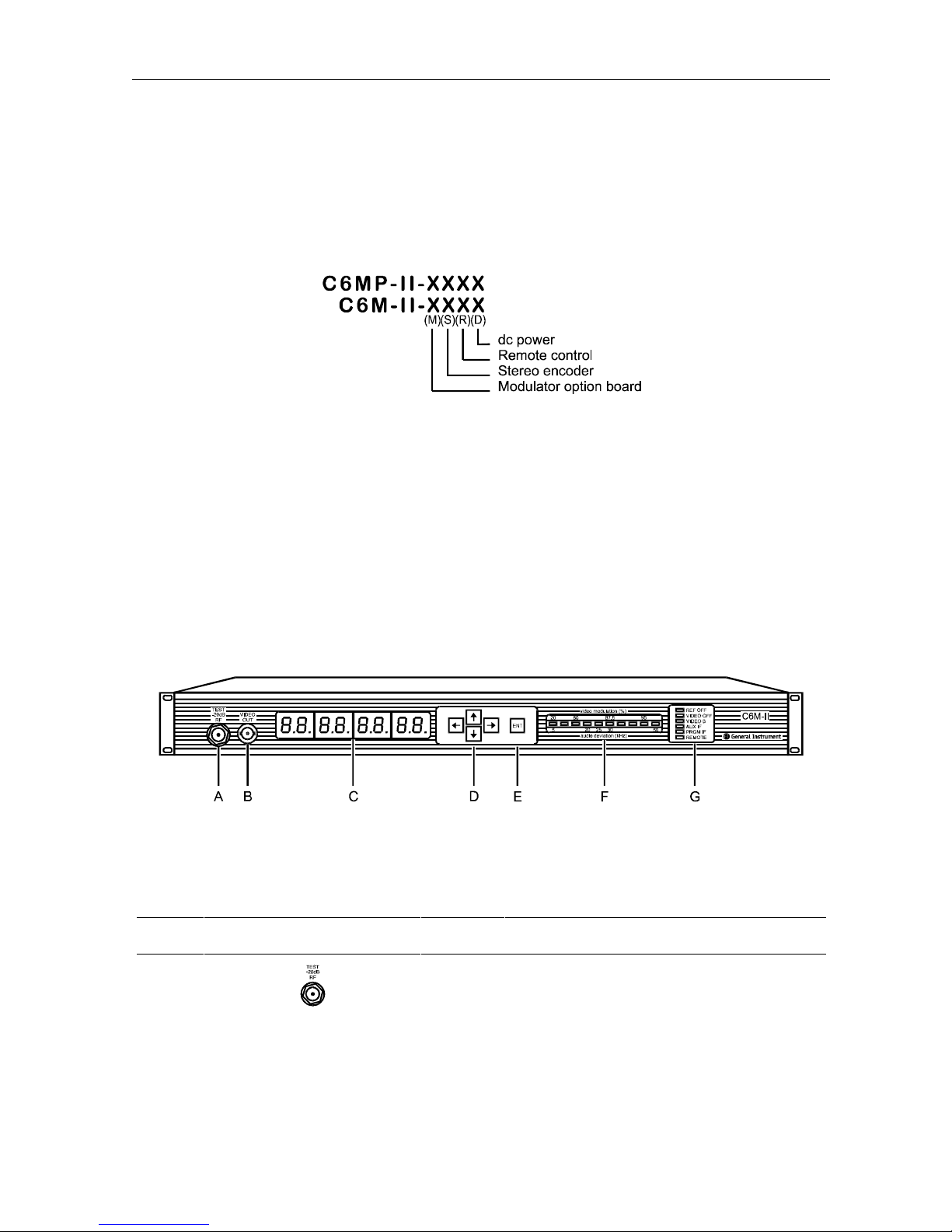
The model as it appears on your unit will reflect the options that are factory installed. The
basic modulator unit without any options is C6M-II-XXXX. The naming conventions are shown
below:
For example, if your model is C6M-II-MXRX, the modulator option board and the remote
control board have been factory installed. The C6MP-II-XXXX is equipped with the external
phase lock capability.
Front Panel Controls and Displays
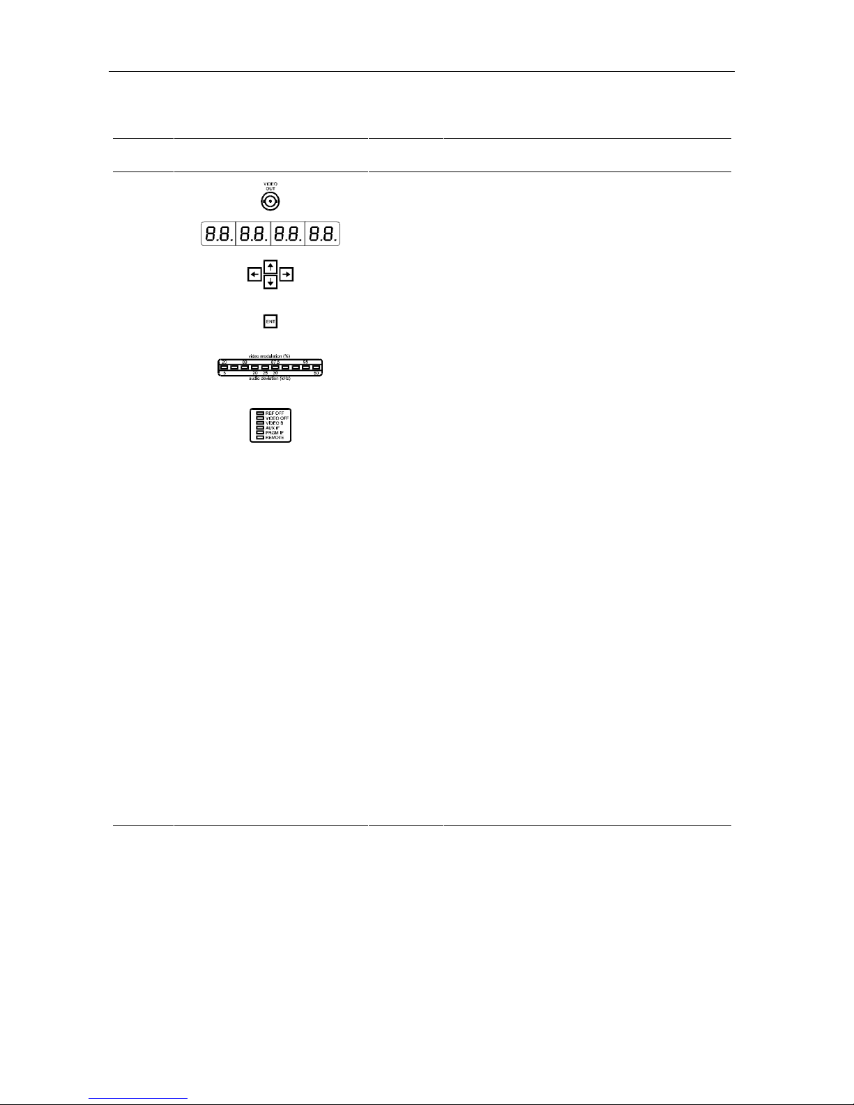
The front panel of the C6M-II modulator, which includes an operational display, test ports, a
keypad for adjustments, a bar graph and a status display, is illustrated in Figure 2-1.
Figure 2-1
C6M-II front panel
The following table describes the function of each item on the C6M-II front panel.
Table 2-2
Description of controls and displays
Key Feature Description
A The −20 dB RF test point connector provides a sample of the
rear panel RF output signal (marked
measured at this connector is −20 dB nominal relative to the
RF output level at the rear panel. The performance of the
unit should not be measured using this test point. This is an
F-type coaxial connector.
RF OUT). The signal level
C6M-II Installation Manual
Page 12
2-4 Overview
Key Feature Description
B The VIDEO OUT provides a buffered video output. This is a
BNC type coaxial connector.
C
The eight-digit alphanumeric LED display shows all functions
and controls used to operate the C6M-II.
D
The keypad with four arrow push buttons is used to navigate
through the menus. When the desired menu item is reached,
the right arrow key is used to access the functions.
E
The ENT (Enter) key implements changes made to functions
and menus.
F
The LED bar graph monitors either depth of video modulation
or audio deviation. The desired function (either VIDEO or
AUDIO) can be selected in the Option menu BAR VID.
G
The operating status display contains the following six LED
indicators:
REF OFF Lights when a comb generator signal is not
applied to the rear panel
REF IN connector or
when the reference signal level is too low (or
missing) for phase lock operation. This function
applies only to units with phase lock capability.
VIDEO OFF Lights when the video signal is absent or when
there is insufficient video signal level at the
selected input,
VIDEO B Lights when VIDEO B is selected as the video
VIDEO A or VIDEO B connector.
input. This applies only if the modulator option
board is installed.
AUX IF Lights when the AUX IF input is selected. The
input signal at this connector is routed to the
upconverter and then to the desired RF output.
PRGM IF Lights when the optional Program IF input is
selected for upconversion to the desired RF
output. This IF input is available only when the
modulator option board is installed.
REMOTE Lights when the remote control function is
activated through the menu. Available only
when the remote control option is installed.
C6M-II Installation Manual
Page 13
Overview 2-5
Rear Panel Connectors
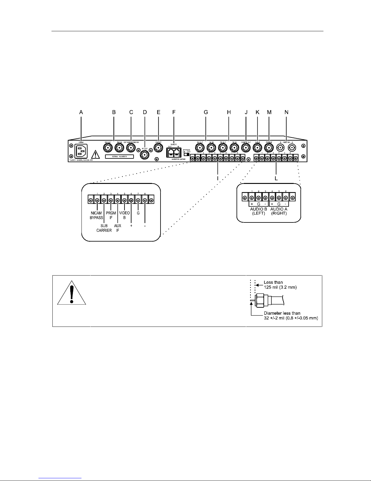
The rear panel of the C6M-II modulator with options installed is illustrated in Figure 2-2.
Figure 2-2
C6M-II rear panel with options installed
Note: All external jumpers take precedence over menu selection. This includes AUX IF,
VIDEO B, SUBCARRIER, and PRGM IF.
WARNING! RF OUT is a high performance RF connector.
Using a cable with a male connector of incorrect
dimensions may cause physical damage. The center
conductor diameter must be less than 32 ±2 mil
(0.8 ±0.05 mm) and shorter than 125 mil (3.2 mm)
measuring from the edge of the connector as illustrated.
C6M-II Installation Manual
Page 14
2-6 Overview
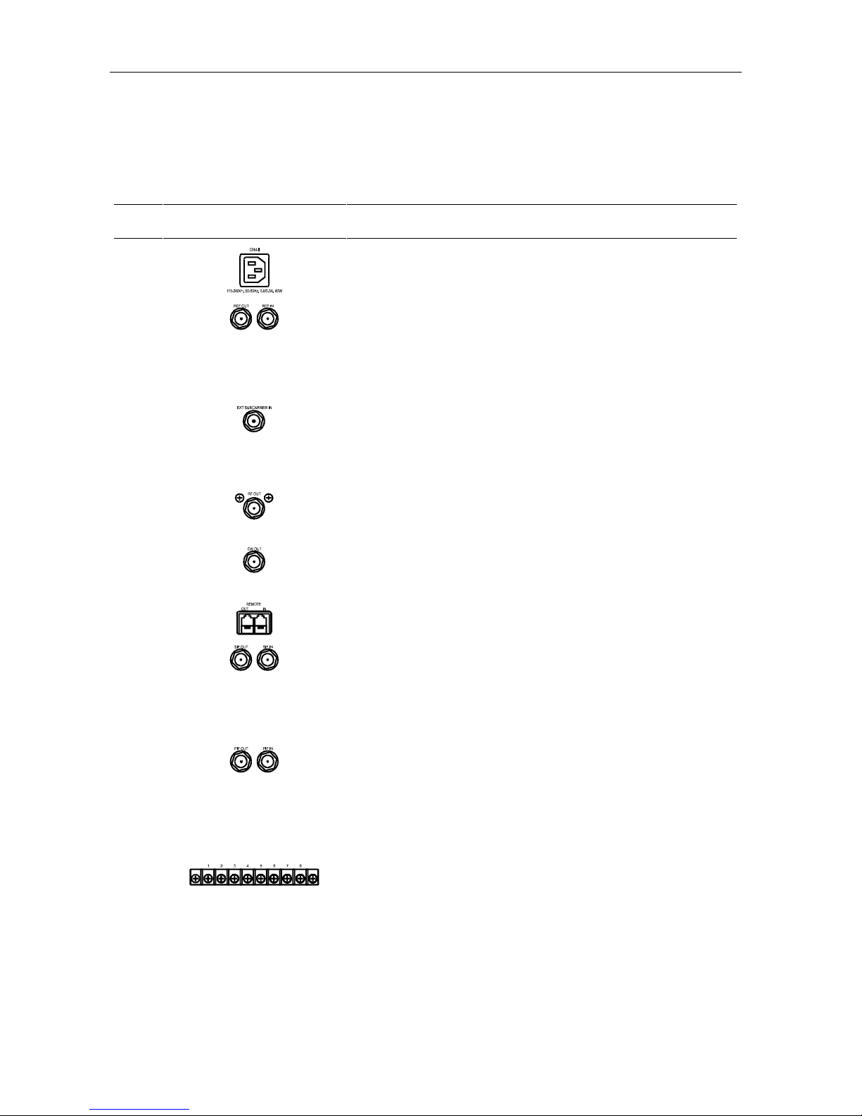
The following table describes the features on the rear panel of the C6M-II modulator.
Table 2-3
Description of rear panel connections
Key Feature Description
A Power line connector. Label indicates input power range.
B
REF OUT and REF IN connectors are used to apply comb generator
reference signals for phase-locked operation. Applicable only for
units with the phase lock option. The
through connection from the
REF IN connector with an insertion
loss of 1.0 dB maximum. The frequency of
REF OUT connector is a loop
REF IN must be 6 MHz.
These are F-type coaxial connectors.
C
The EXT SUBCARRIER IN connector accepts a monophonic or stereo
FM modulated 4.5 MHz audio subcarrier signal with a level of 50
to 200 mV rms. It also accepts composite baseband (video plus
4.5 MHz subcarrier). Available only when the modulator option
board is installed. This is a F-type coaxial connector.
D
RF OUT connector. This is the RF channel output. The modulated
video and audio carrier signals appear here. The output level is
adjusted through the menu. This is an F-type coaxial connector.
E
The CW OUT connector provides a + 50 dBmV minimum
unmodulated picture IF carrier for use with the MVP-II video
processor. This is an F-type coaxial connector.
F
REMOTE connectors. See the remote control option installation
manual for details on the function of these connections.
G
SIF OUT and SIF IN connectors are jumpered during normal
operation. The
SIF OUT connector has FM modulated sound IF
signal (41.25 MHz) at a nominal level of 10 to 30 dBmV,
depending on the audio level selected on the main menu. The
IN
connector is capable of passing a monophonic or stereo
SIF
modulated sound IF carrier. These are F-type coaxial connectors.
H
I
C6M-II Installation Manual
PIF OUT and PIF IN connectors are jumpered during normal
operation.
The
nominal level of 35 dBmV. Since the
PIF OUT can be used to interface with an IF scrambler.
PIF OUT connector is a modulated picture IF carrier at a
PIF IN connector precedes a
sound acoustic wave (SAW) filter, a composite IF signal (picture
IF plus sound IF) should not be applied to the
PIF IN connector.
These are F-type coaxial connectors.
SUBCARRIER, PRGM IF, AUX IF, and VIDEO B selection terminals are
activated by connecting them to one of the ground terminals on
the strip. When equipped with the stereo encoder option and
modulator option board,
AUDIO B/SE input is available. Audio B is
monaural only. The functions of these features are described in
Section 3, Installation
.
Page 15
Overview 2-7
Key Feature Description
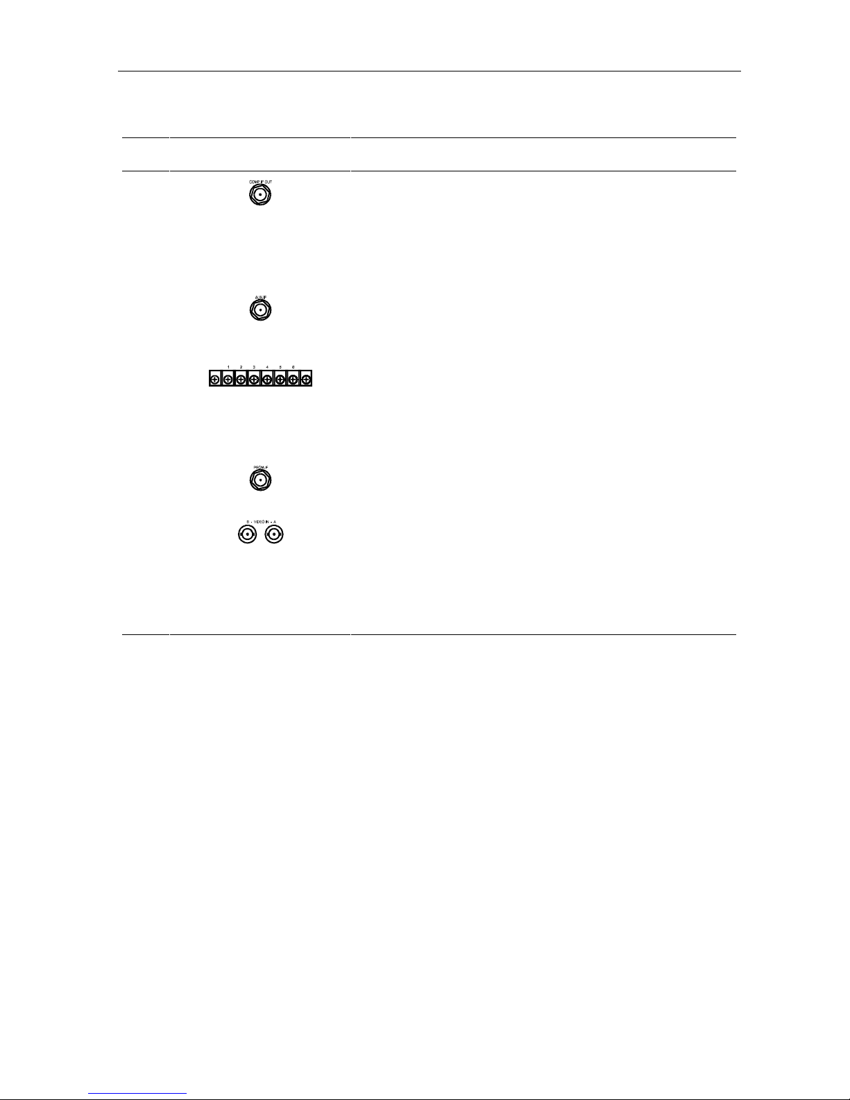
J The COMP IF OUT connector provides access to the internally
modulated composite IF signal at a nominal 30 dBmV level. The
video and audio correspond to the signal selected from the
A
/B and AUDIO A/B inputs, subcarrier or composite baseband (video
plus 4.5 MHz subcarrier inputs). If no video or audio signals are
present at the selected input, the signal consists of unmodulated
picture and sound carriers. This is an F-type coaxial connector.
VIDEO
K
The AUX-IF input connector accepts an alternate composite IF
signal. This input precedes the IF gain control circuitry and can
accept a level range from 25 to 35 dBmV. This is an F-type
coaxial connector.
L
AUDIO A input is normally a balanced 600 ohm input with a ground.
This can be switched using the menu to a high impedance input
(15 kohms). To switch to the high impedance input, choose
AUDZ HI on the Audio menu. The optional
identical to the
AUDIO A input and is activated whenever the VIDEO B
AUDIO B input is
input is selected.
M
PRGM-IF input has the same signal characteristics as the AUX IF
input. Available only when the modulator option board is installed.
This is an F-type coaxial connector.
N
VIDEO IN A is the primary video input connector (75-ohm baseband
video).
modulator option board is installed.
through the video menu or by shorting to ground the
VIDEO IN B is an optional input available only when the
VIDEO IN B may be selected
VIDEO B
terminal on the rear panel. VIDEO IN B will be activated in when
loss of video is detected on
VIDEO IN A if this feature is enabled
through the menu. These are BNC type coaxial connectors.
C6M-II Installation Manual
Page 16
2-8 Overview
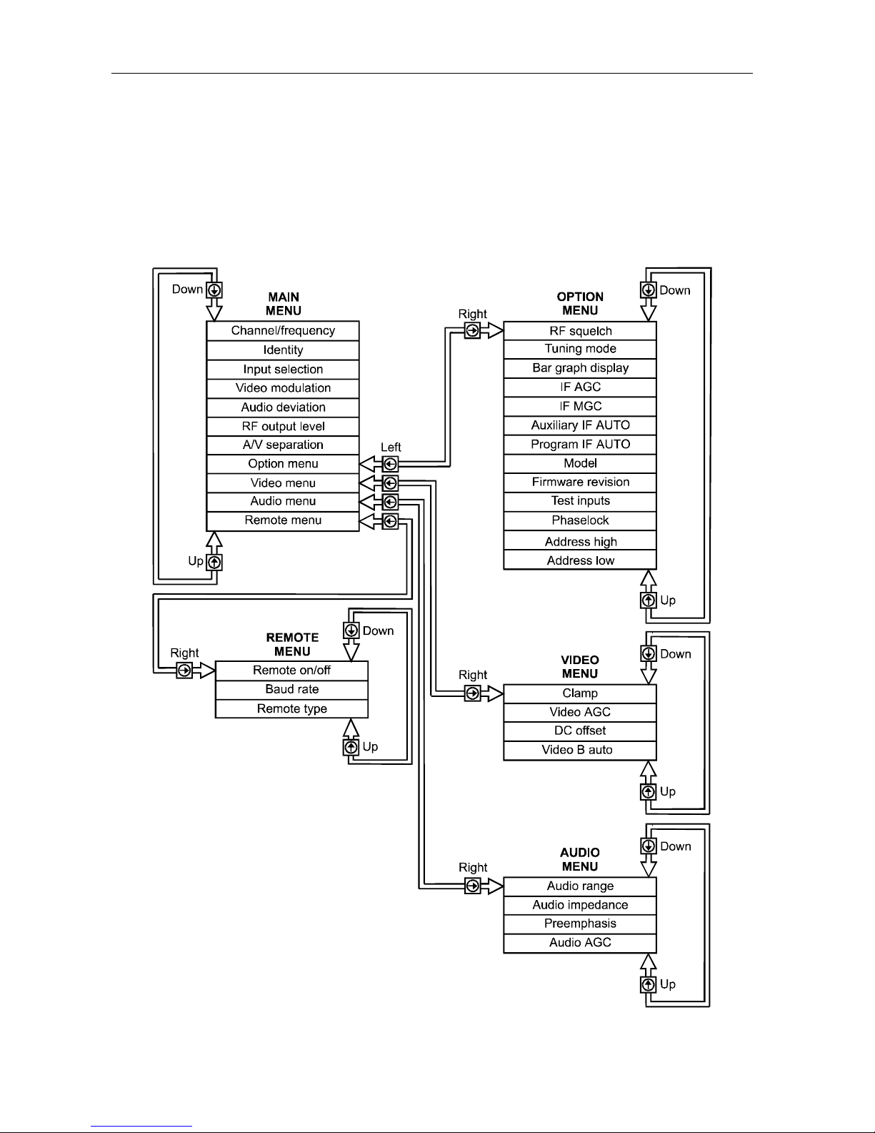
The Menu System
The C6M-II is operated by menus which are accessed by the four push buttons and the ENT key
located on the front panel. The relationship of the menus is shown graphically in Figure 2-3.
Figure 2-3
Menu relationships
C6M-II Installation Manual
Page 17

Overview 2-9
Using the Menus
When the unit is powered, the first item on the Main menu appears on the LED display. To
reach any other main menu item, use the up or down arrow key. To move to the Option, Audio,
Video, or Remote menu, select its name on the LED display (via the Main menu) and then
press the right arrow key. To return to the Main menu, press the left arrow key.
To change a menu item, display the desired item and press the right arrow key. This will
cause the changeable portion to flash. Press the up or down arrow keys until the desired item
or value is reached. Press
ENT to implement the new value. If the new value is not
implemented, the item will return to its previous state after a short delay.
If the display shows NA, it indicates Not Available or Not Applicable.
Changing a Menu Item
When changing any menu item, follow these general procedures:
If the item is located on the Main menu, display it using the up and down arrow keys.
If the item is located on the Option, Audio, Video or Remote menu, use the up or down
arrow key to display its name on the Main menu. Press the right arrow key to display the
first item on the desired menu. Then use the up or down arrow key to display the menu
item you wish to change.
Once you display the menu item you want to configure, press the right arrow key. The
changeable portion of the menu item flashes.
Use the up or down arrow key to change the value to the desired value or option.
To implement the change, press the ENT key.
If you decide not to make the change, press the left arrow key to exit the menu, or take no
action. If you take no action, the flashing value will revert to the previous value after a
short delay.
See Appendix C, Changing a Menu Item for a step-by-step description of how to change a menu
item.
C6M-II Installation Manual
Page 18
2-10 Overview
Main Menu
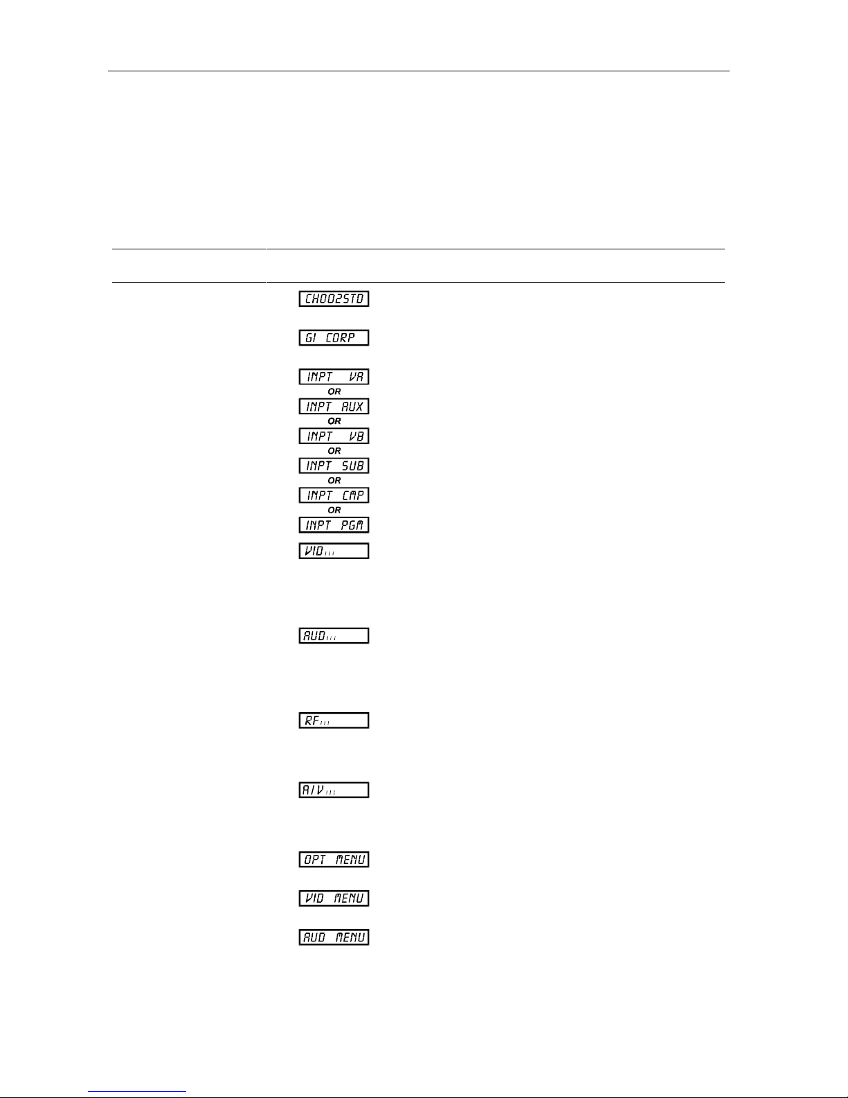
The following table illustrates the display and describes the function of each item on the Main
menu.
Table 2-4
Description of Main menu items
Main Menu Item Appearance Description
Channel/Frequency Displays the channel number or frequency of the RF
output.
Identity
Input Selection
Video Modulation
Audio Deviation
RF Output Level
Alphanumeric display of name assigned to the
modulator by the user.
Allows switching by menu to VIDEO A, AUX IF, or the
optional inputs: VIDEO B, EXT SUBCARRIER IN
COMPOSITE BB IN or PRGM IF.
Adjusts the depth of video modulation. Increase or
decrease by holding down the up or down arrow key
until the desired depth is reached. Press
ENT to
implement the change. When in this menu, the LED
bar graph display indicates the depth of modulation.
Adjusts the deviation of FM modulation. Increase or
decrease by holding down the up or down arrow key
until the desired deviation is reached. Press
ENT to
implement the change. When in this menu, the LED
bar graph display indicates audio deviation.
Adjusts the RF output level. Increase or decrease by
holding down the up or down arrow key until the
desired level is reached. Press
ENT to implement the
change.
Audio/Video
Separation
Option Menu
Video Menu
Audio Menu
C6M-II Installation Manual
Adjusts the amplitude separation between the audio
and video carriers. Increase or decrease by holding
down the up or down arrow key until the desired level
is reached. Press
ENT to implement the change.
Provides access to the option menu. Press the right
arrow key to enter the option menu.
Provides access to the video menu. Press the right
arrow key to enter the video menu.
Provides access to the audio menu. Press the right
arrow key to enter the audio menu.
Page 19
Overview 2-11
Main Menu Item Appearance Description
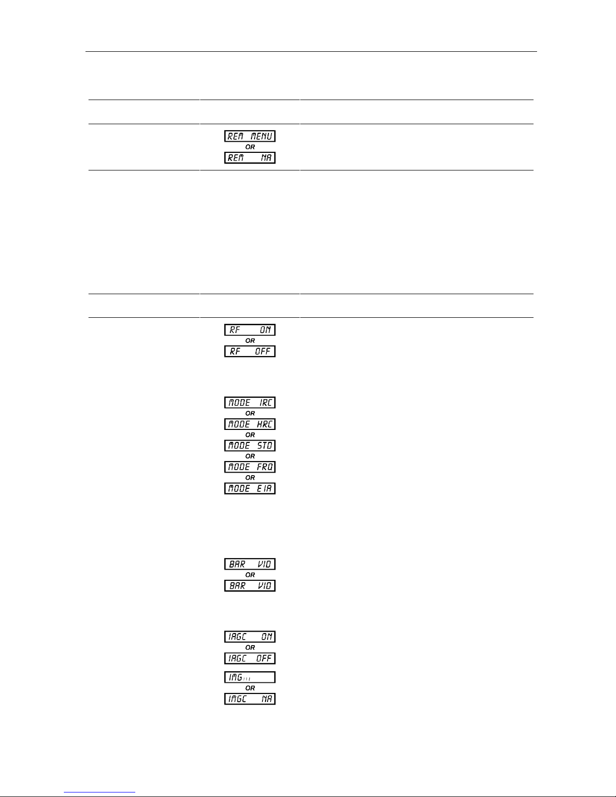
Remote Menu Provides access to the remote menu when the option
is installed. NA means not available.
Option Menu
To access the Option menu, display OPT MENU on the Main menu. To reach any item on the
menu, use the up or down arrow key. The following table describes each item on the Option
menu.
Table 2-5
Description of Option menu items
Option Menu Item Appearance Description
RF Squelch Allows RF output to be turned on or off. The right
arrow key causes the item (e.g., ON) to flash. The up
arrow key toggles between ON and OFF. Pressing
ENT implements the choice. This menu item is mainly
for testing, and should always be ON for normal
operation.
Tuning Mode
Bar Graph Display
Automatic Gain
Control (IF AGC)
Manual Gain Control
(IF MGC)
Selects the frequency plan. The choices are IRC,
HRC, STD, FRQ, and EIA. The right arrow key
causes the choice (e.g., STD) to flash. The up or
down arrow key pages through the flashing choices
(IRC, HRC, STD, FRQ, EIA). The
ENT key implements
the choice. If FRQ is chosen, the RF output frequency
appears and the desired frequency must be entered by
using the up or down arrow key. For any other choice
(e.g., STD) the channel number flashes. The channel
number must then be entered by using the up or down
arrow key. After selecting the channel number, press
ENT to implement the choice. When the change is
made, the system automatically exits to the Main
menu.
Indicates whether the LED bar graph is being used to
display video depth of modulation or audio deviation.
The right arrow key causes the item to flash, and the
up or down arrow key toggles between VID (video
modulation) and AUD (audio deviation). Pressing
ENT
implements the choice.
Toggles IF AGC between ON (IAGC ON) and OFF
(IAGC OFF) For normal operation, it should be on.
If IF AGC is turned off, MGC is available.
C6M-II Installation Manual
Page 20

2-12 Overview
Option Menu Item Appearance Description
Auxiliary IF AUTO Turns ON or OFF the option to use Auxiliary IF
automatically if video signals (A or B) are lost.
Program IF AUTO
Model Number
Firmware Revision
Test Inputs
Phaselock
Address High
This is available only if the modulator option board is
installed. Turns ON and OFF the option to use
Program IF automatically if video A or B signals are
lost.
Displays the model designation of the unit.
Displays the firmware revision number.
Selects the input sources to the unit. The selection is
not permanent. Used for testing or troubleshooting
input sources. CMP, SUB, VB, and PGM are available
only if the modulator option board is installed.
AUT indicates that the REF IN connector is available to
automatically accept and lock an external
phase-locked reference signal. INT allows use of the
internal reference signal even if
REF IN is available.
Displays the first seven characters of the unit remote
control address. The address is same as the serial
number. Address is factory programmed and cannot
be changed.
Address Low
C6M-II Installation Manual
Displays the last six characters of the unit remote
control address.
Page 21

Overview 2-13
Video Menu
To access the Video menu, display VID MENU on the Main menu. To reach any item on the
menu, use the up or down arrow key. The following items appear on the Video menu.
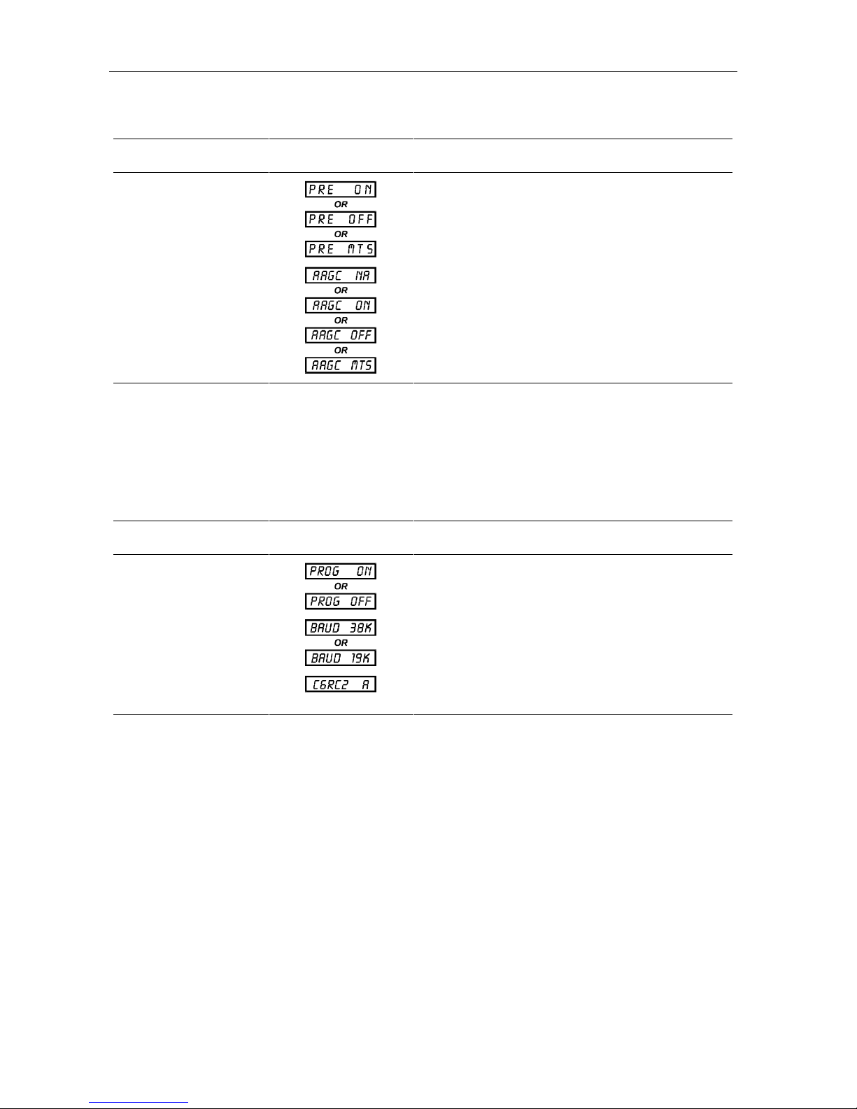
Table 2-6
Description of Video menu items
Video Menu Item Appearance Description
Clamp Toggles video clamp ON or OFF. For normal
operation, the clamp must be on.
Video AGC
DC Offset
Video B Auto
Available when the modulator option board is
installed. Turns video AGC ON or OFF.
Adjusts video dc offset. Only available when video
clamp is off and Video AGC is off or NA.
A → B ON indicates automatic switching to
VIDEO B / AUDIO B when VIDEO A is missing.
Available only when the modulator option board is
installed.
Audio Menu
To access the Audio menu, display AUD MENU on the Main menu. To reach any item on the
menu, use the up or down arrow key. The following items appear on the Audio menu.
Table 2-7
Description of Audio menu items
Audio Menu Item Appearance Description
Audio Range Toggles between two audio input ranges: HI (+5 to
Audio Impedance
+25 dBm) and LOW (−10 to +10 dBm). When the
stereo encoder is in operation, it is set to LOW,
displays MTS, and this cannot be changed.
Toggles between two different input impedance.
LOW indicates a 600 ohm balanced. HI indicates
greater than 15 kohms. When the stereo encoder
option is in operation, it is set to HI, displays MTS,
and cannot be changed.
C6M-II Installation Manual
Page 22
2-14 Overview
Audio Menu Item Appearance Description
Preemphasis Turns audio pre-emphasis ON or OFF. When the
stereo encoder option is in operation, it is set to OFF,
displays MTS, and cannot be changed. The stereo
encoder has built-in pre-emphasis circuitry.
Audio AGC
Toggles audio AGC between ON and OFF. Available
when modulator option board is installed. When the
stereo encoder option is in operation, it is set to OFF,
displays MTS, and cannot be changed. The stereo
encoder has built-in AGC circuitry.
Remote Menu
When the optional C6-RC-II is installed, the following items appear on the Remote menu.
Table 2-8
Description of Remote menu items
Remote Menu Item Appearance Description
Remote on/off Toggles between ON and OFF. It must be ON for
remote operation. When turned ON, operating
parameters cannot be changed locally.
Baud rate
Displays communication rate. This parameter cannot
be changed.
Remote type
C6M-II Installation Manual
Displays the remote control type. This parameter
cannot be changed.
Page 23

Overview 2-15
Warning Messages
Flashing messages appear on the front-panel LED display to inform you of the current status of
the modulator.
All warning messages are described in the following table.
Table 2-9
Description of flashing messages
Flashing Message Appearance Meaning
UNLOCKED The unit has a major internal problem. It automatically
turns off the RF output. The unit should be returned
for repair. See
instructions.
Section 1, Introduction
for repair
RF OFF
ALT INPT
MTS UNKD
REMOTE
REAR PAN
RF output is squelched.
Alternate input source is being used. This message is
displayed when the user-selected input is absent or
below threshold level.
Stereo encoder is not operating properly. Ensure that
the video input to video A is within specified range. If
the video range is sufficient, the unit should be
returned for repair. See
repair instructions.
The unit is under remote control while attempting to
change parameters. The remote control must be
turned off before parameter changes can be made
through the front panel menu.
Attempt to change the input source while it is selected
through the rear panel terminal block. Input selection
by the terminal block has the highest priority. See
Appendix D, Signal Priority Chart
Section 1, Introduction
.
for
C6M-II Installation Manual
Page 24

Section 3
Installation
This section provides step-by-step instructions for installing the C6M-II, checking its operation
and connecting it to other equipment. In this process, the following tasks are performed:
Mount the modulator.
Set all customized features.
Select RF channel frequency.
Attach cables.
Before You Begin
Before beginning the installation, check that you have the following items with the C6M-II
unit:
Power cord Acceptable for use with NEMA Style 5-15R ac receptacles
supplying nominal 120 Volts.
Two F-type 75-Ohm coaxial jumpers Provided to connect
Two F-type 75-Ohm male terminators Provided to terminate
Four mounting screws with plastic
washers
Spade lugs wire terminals Provided for manual connections on the terminal block.
Five screws with split ring washers Provided as spares parts for the terminal block.
If you are installing the C6M-II in a system that currently has a C6M and will operate in a
range higher than 600 MHz, an external lowpass filter, model C6-LPF600 (928-363-000) or
equivalent should be included. This filter is used to attentuate spurious carriers occurring
above 600 MHz. The filter is installed either at the RF output of the C6M or at the combined
output. Appendix E, Application Notes provides instructions for installing this filter.
Provided to mount the unit in the rack.
SIF IN to SIF OUT and PIF IN to PIF OUT.
CW OUT and COMP IF OUT.
Mounting the Modulator
Mount the modulator in a standard 19-inch rack. Provide an open space of 1.75 inches above
and below the modulator to allow for the free flow of air. If the equipment operates
continuously in a closed cabinet, use forced air circulation to ensure maximum equipment life
and optimum performance.
To maximize product life, refer to National Electric Code (NEC) guidelines for proper
grounding of the C6M-II to equipment racks, and to the grounding system of the building.
C6M-II Installation Manual
Page 25
3-2 Installation
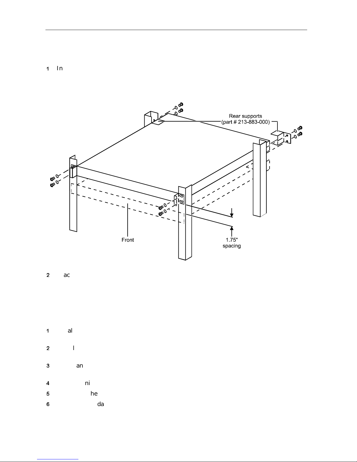
To fasten the unit in place:
Insert screws through the four mounting holes in the front panel as shown in Figure 3-1.
Figure 3-1
Rack mounting
Brace the unit with rear supports for improved stability as shown in Figure 3-1.
Checking the Operation
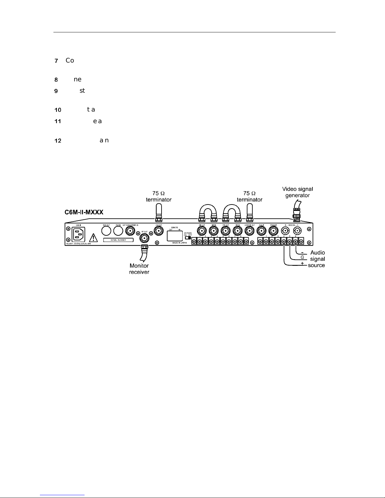
The connections for the operational check are shown in Figure 3-2. To test the basic operation
of the unit, follow this procedure:
Install an F-type coaxial cable jumper between the PIF IN and PIF OUT connectors on the
rear panel.
Install an F-type coaxial cable jumper between the SIF IN and SIF OUT connectors on the rear
panel.
Install an F-type 75 Ohm terminator on the COMP IF OUT and IF CW OUT connectors on the
rear panel.
Plug the unit into an appropriate power line and allow it to warm up for five minutes.
Check that the VIDEO OFF and REF OFF indicators glow steadily.
Connect a standard baseband video signal generator to the VIDEO IN A connector on the rear
panel.
C6M-II Installation Manual
Page 26
Installation 3-3
Connect a receiver to the RF OUT connector on the rear panel through a 40 or 50 dB
attenuator.
Tune the modulator and the receiver to the same channel.
Adjust the depth of modulation to 87.5 percent using the video modulation adjustment in
the Main menu. Appropriate test equipment must be used.
Connect an audio signal source to the AUDIO A input on the rear panel.
Adjust the audio deviation to ± 25 kHz using the Audio deviation adjustment in the Main
menu. Appropriate test equipment must be used.
Verify that a noise-free video signal is on the monitor and that a noise-free audio signal is
coming from the speaker.
Figure 3-2
Operational check connections
Switching Capabilities
The applications below describe a few of switching features of the C6M-II. For other switching
applications, refer to Appendix D, Signal Priority Chart.
Without the MOB Option Board
When the video signal VIDEO A is lost, automatic switching to the AUX IF input can be selected
via menu. When the video signal returns and the C6M-II detects its presence, it will switch
back to the
With the MOB Option Board
When the MOB option board is installed, automatic baseband video and audio input switching
is available. The following options describe only a few of the automatic switching features of
the C6M-II. Refer to Appendix D, Signal Priority Chart for a complete block diagram of the
switching priorities.
VIDEO A. To activate this feature, select AUXA ON from the Option menu.
C6M-II Installation Manual
Page 27

3-4 Installation
n
When the video signal to VIDEO A is missing, the C6M-II automatically switches to video B
as the backup source. It will return to video A when the unit detects video A presence. To
activate this feature, select A→B ON from the Video menu.
n
When either video A or B is lost, automatic switching to the PRGM-IF input can be selected
via the menu. To activate this feature, select PGMA ON from the Option menu.
n
When the video signal to video A is missing, the C6M-II automatically switches to video B
as the backup source. If video B is also missing, the unit can switch to
return to video B input if detected. It will return to video A when presence is detected,
even if VIDEO B is present. On the Video menu, select A→B ON and on the Option menu,
select AUXA ON. This application can be used for backup switching capability.
n
When the video signal to video A is missing, the C6M-II automatically switches to video B
as the backup source. If video B is also missing, the unit can switch to
return to
VIDEO B input if detected. The unit switches to video A when video A presence is
detected, even if video B is present. On the Video menu, select A→B ON and on the Option
menu, select PGMA ON.
n
When an Emergency broadcast is necessary, the PRGM IF terminal on the rear panel can be
activated by connected ground. The unit will remain switched until the terminal is
connected to +5V dc. Refer to Rear Panel Connections in Section 2. The rear panel input
selection has the highest priority. Rear panel connectors are connected to +5 V internally.
AUX IF. It will
PGMA IF. It will
Automatic Gain Control
IF AGC
IF AGC is provided so that IF switching can be used without having to critically balance the
levels of the IF signal sources. This AGC is the video sync tip referenced peak detector type
and must be turned on for normal operation.
If the sync information is modified by scrambling or some other process, a constant peak
reference will no longer be available for AGC operation. This will cause variation in carrier
level with picture content. Therefore, IF AGC operation must be turned off when sync
suppression scrambling is present.
To turn off the IF AGC, go to the Option menu and choose IF AGC. Change from IAGC ON to
IAGC OFF. If necessary, IF level can be adjusted manually using the manual gain control
menu item. On the Option menu, select IMG.
Baseband AGC (Optional)
When the MOB option board is installed, both video and audio automatic gain control are
available.
For video, this function maintains a preset video depth of modulation despite changes in video
input levels resulting from variations in video source levels or from video source switching. To
activate the video AGC, go to the Video menu and choose Video AGC (VAGC). Change from
VAGC OFF to VAGC ON.
C6M-II Installation Manual
Page 28

Installation 3-5
For audio, this function maintains a preset audio deviation despite changes in audio input level
resulting from audio source variations or from audio switching. To activate the audio AGC, go
to the Audio menu and choose Audio AGC (AAGC). Change from AAGC OFF to AAGC ON.
When the optional stereo encoder is in operation, Audio AGC cannot be changed.
Audio Parameters
Audio Impedance
Audio impedance has two settings, 600 Ohms and greater than 15 kohms. The value is set
through the Audio menu. Go to the Audio menu and choose either Audio Impedance Low
(AUDZ LOW) which is 600 Ohms, or Audio Impedance High (AUDZ HI) which is greater than
15 kohms.
Audio Level
There are two ranges for the input audio signal: −10 to +10 dBm and +5 to +25 dBm. The
range is set through the Audio menu. Go to the Audio menu and choose Audio Range Low
(AUDR LOW) which is − 10 to + 10 dBm, or Audio Range High (AUDR HI) which is + 5 to
+ 25 dBm.
Stereo Encoder (Optional)
When the stereo encoder option is installed in the unit, the following audio parameters cannot
be changed: audio input range, input impedance, pre-emphasis, and AGC. Audio A can be
stereo encoded while Audio B is always monaural.
Selecting the RF Channel Frequency Plan
The C6M-II meets the FCC Part 76 Frequency Rules.
The C6M-II operates in STD, HRC, EIA or IRC modes. The difference between the IRC and
Standard frequency plans is the following:
n
For the HRC and IRC Phaselock Mode, channels 54, 55 and 56 are used in the low band in
place of channels 5 and 6.
n
For the Standard Mode, channels 5 and 6 are located at the standard frequency
assignments. Channels 54, 55 and 56 are at the IRC frequencies. Channels 42, 60 and 61
have the + 25 kHz FCC frequency offsets built in.
The C6M-II has the capability to output any frequency in increments of 12.5 kHz if needed. If
AUX IF and/or PRGM IF is used in HRC, IF frequency must be 45.7522875 MHz.
To select a mode, go to the Option menu and choose Tuning mode. Select either MODE IRC,
MODE HRC, MODE STD, MODE EIA or MODE FREQ.
Appendix B, Frequency Plan shows the relationship between channel and frequency for the
four modes.
C6M-II Installation Manual
Page 29
3-6 Installation
Typical Interconnections
Basic Video and Audio Interfacing
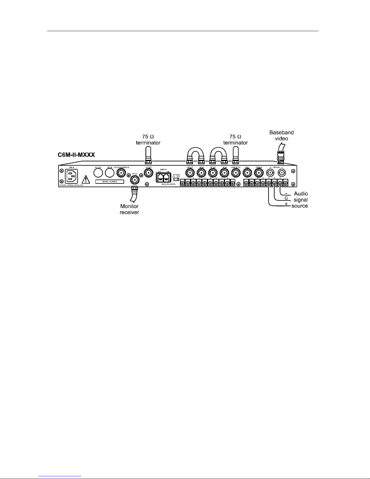
Figure 3-3 shows the standard connections for a video and audio input, and RF output.
Figure 3-3
Basic video/audio interfacing
C6M-II Installation Manual
Page 30
Installation 3-7
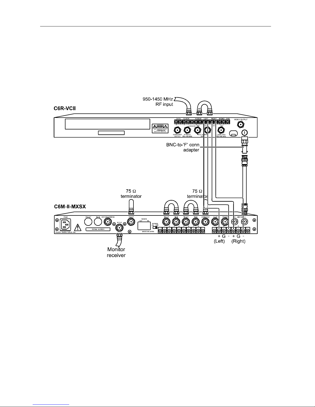
Satellite Link Connection
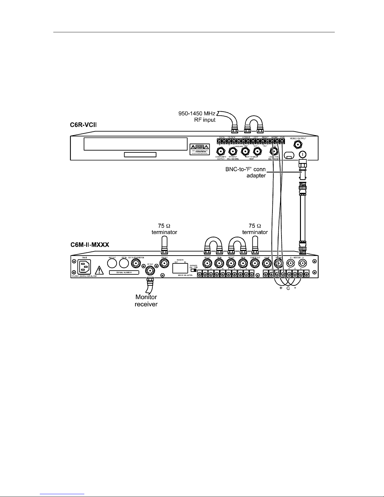
Figure 3-4 shows the connection between the C6R-VCII satellite receiver and the C6M-II.
Figure 3-4
Satellite link connection
C6M-II Installation Manual
Page 31
3-8 Installation
Satellite Link Connection with C6M-II-SE
Figure 3-5 shows the connection between the C6R-VCII satellite receiver and the C6M-II with
the Stereo Encoder option installed.
Figure 3-5
Satellite link connection with stereo encoder
C6M-II Installation Manual
Page 32
Installation 3-9
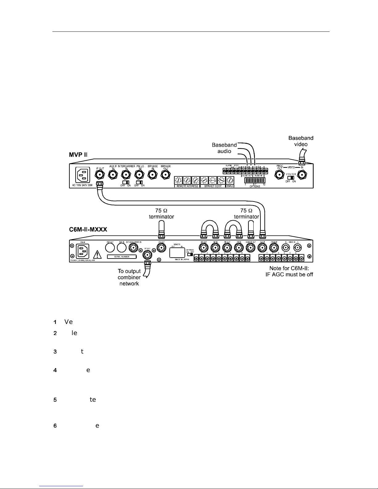
Video Scrambling
The C6M-II can be connected to a General Instrument Modulating Video Processor (MVP II)
for video and audio scrambling as displayed in Figure 3-6.
Note: General Instrument recommends using the C6U dual upconverter to interface with the
MVP II.
Figure 3-6
MVP II / C6M-II IF interfacing
When connecting the MVP II to the C6M-II, use the IF set up in the MVP II Installation
Manual and the following steps for connecting the C6M-II:
Verify that the MVP II is in standby mode.
Select video A input (INPT VA) on the Main menu and activate IF AGC on the Option
menu display
Tune to a test channel. Ensure that appropriate test equipment is connected to RF OUT on
the rear panel.
Measure the RF output and check for the following conditions:
If the RF video carrier output is less than 60 dBmV, adjust the RF output on the C6M-II for
60 dBmV.
Deactivate the IF AGC on the Option menu display and select auxiliary IF (INPT AUX) on
the Main menu as the input. When sync suppression scrambling is used, IF AGC
turned off in the C6M-II
Monitor the test equipment to verify 60 dBmV is still present at the RF output.
must be
C6M-II Installation Manual
Page 33
3-10 Installation
If the RF level is not 60 dBmV, the
COMP IF control on the MVP II can be adjusted. Do not
exceed 32 dBmV at the IF output of the MVP II. If the RF level is still not 60 dBmV, use
manual IF gain control on the Option menu to set RF level. Do not use RF level control to
set the RF output level at this stage.
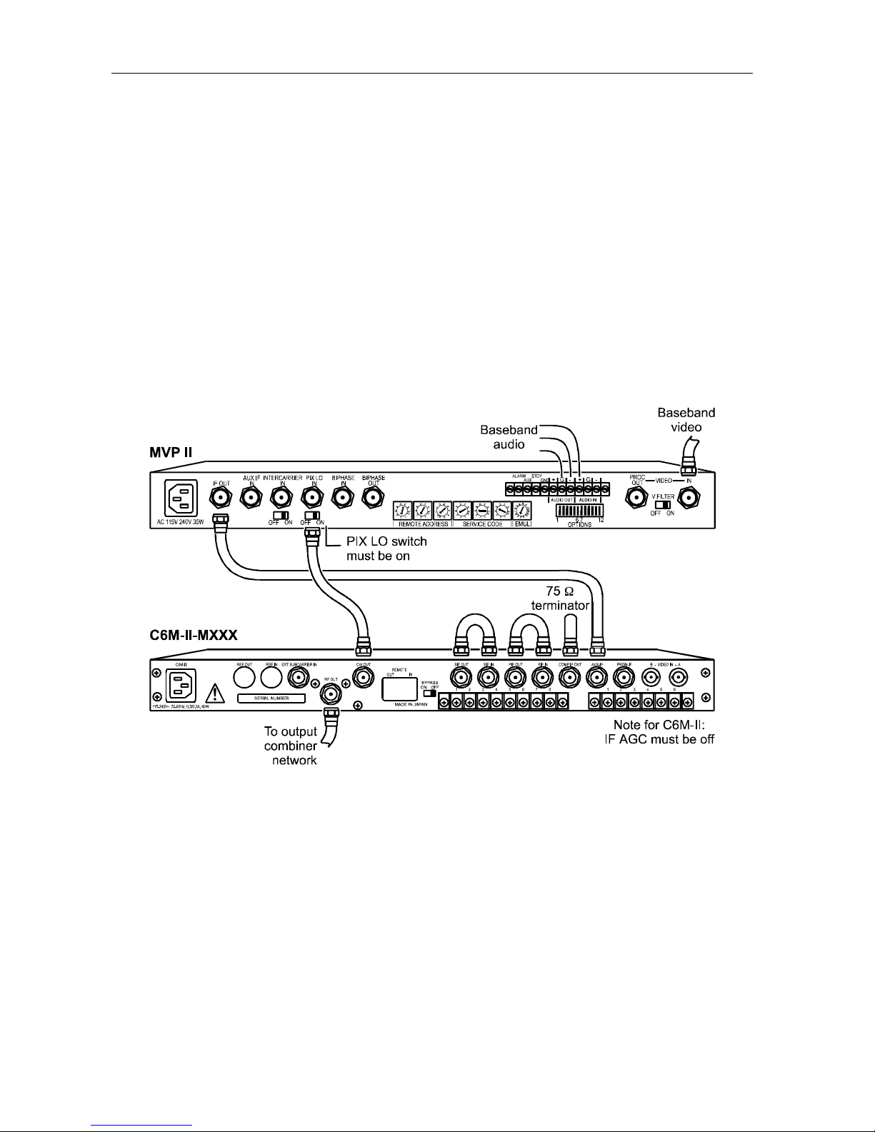
CW Output
The CW output is a 45.75 MHz carrier signal that can be used with the MVP II when it is
necessary to insert a coherent IF carrier for phase-locked upconversions.
Figure 3-7 illustrates the connection of the C6M-II and the MVP II in a phase-locked
upconversion.
Figure 3-7
MVP II / C6M-II interfacing using the CW output
C6M-II Installation Manual
Page 34
Installation 3-11
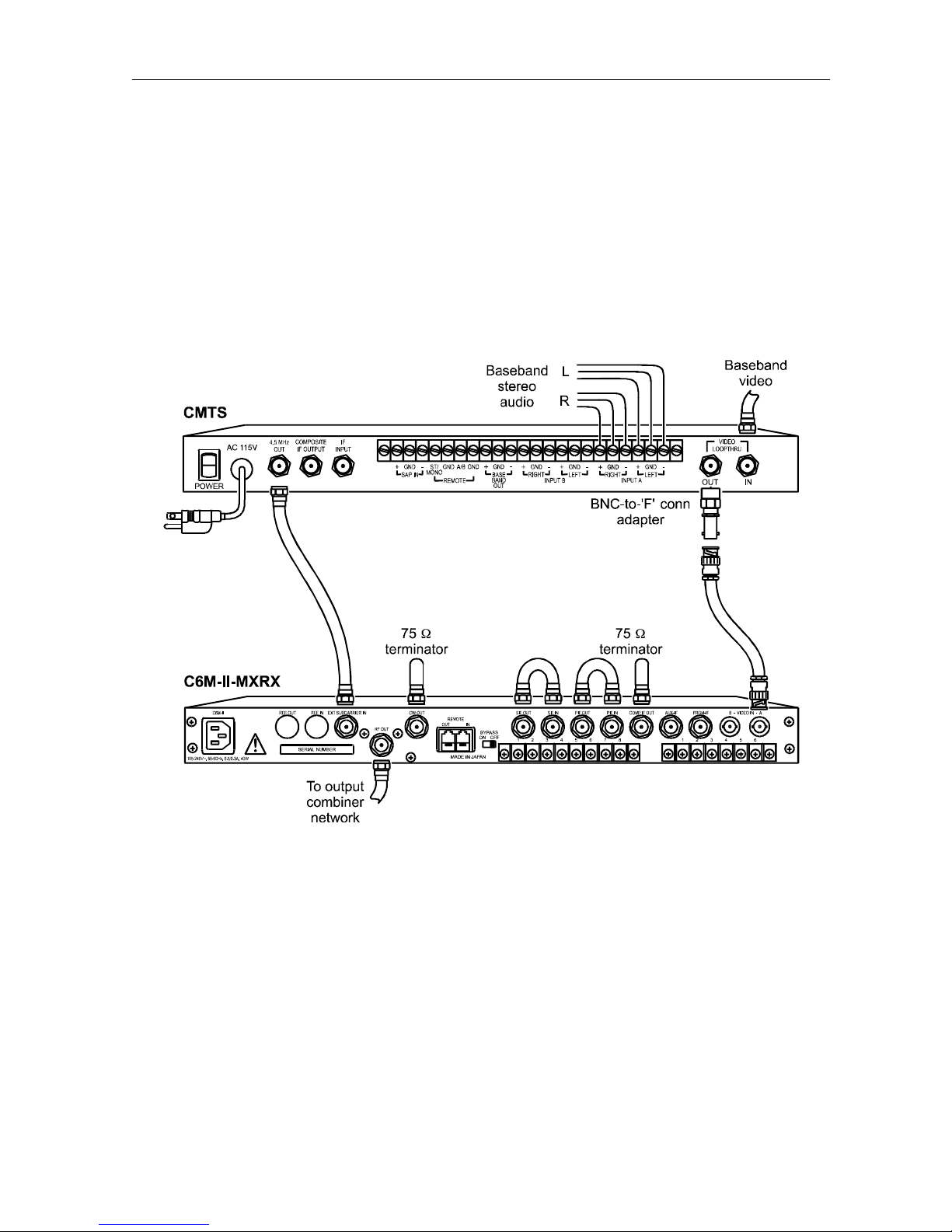
Stereo IF Interfacing
The CMTS stereo encoder can be used with the C6M-II as shown in Figure 3-7 if the MOB
option board is installed. To activate the subcarrier input, select the Input selection menu item
INPT SUB on the Main menu or short the subcarrier terminal on the rear panel to the ground
terminal.
Use the level adjustment on the CMTS front panel to adjust the RF output sound carrier level.
Figure 3-8
C6M-II / CMTS IF interfacing
C6M-II Installation Manual
Page 35
3-12 Installation
Composite Baseband Interfacing
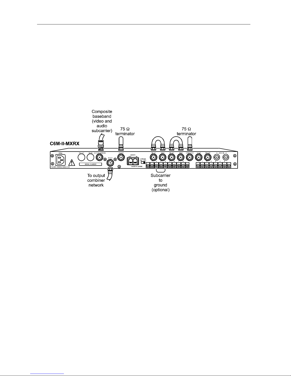
If the MOB option board is installed, an external composite baseband can be accepted. To use
the external composite baseband input, connect the unit as shown in Figure 3-9. To activate,
select the Input selection menu item INPT CMP on the Main menu or short the subcarrier
terminal on the rear panel to the ground terminal. Menu selection is recommended.
The short on the rear panel is not required if the INPT CMP option is selected via the menu.
Figure 3-9
External composite baseband connection
C6M-II Installation Manual
Page 36
Installation 3-13
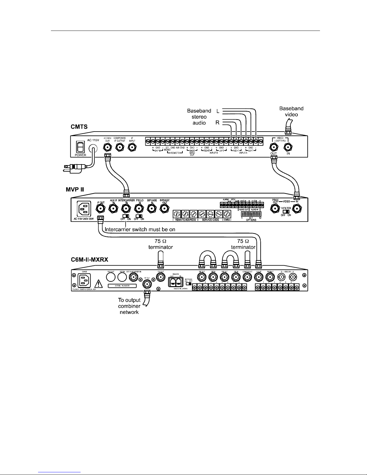
CMTS / MVP II / C6M-II Connections
Figure 3-10 shows the connections between the CMTS, MVP II and C6M-II.
Figure 3-10
C6M-II / MVP II / CMTS interfacing
C6M-II Installation Manual
Page 37
3-14 Installation
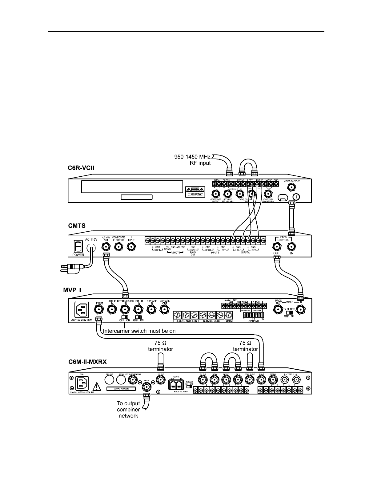
C6R-VCII / CMTS / MVP II / C6M-II Connections
Figure 3-11 shows the connections between the C6R-VCII, CMTS, MVP II and C6M-II.
Figure 3-11
C6R-VCII / CMTS / MVP II / C6M-II connections
C6M-II Installation Manual
Page 38
Section 4
System Block Diagrams
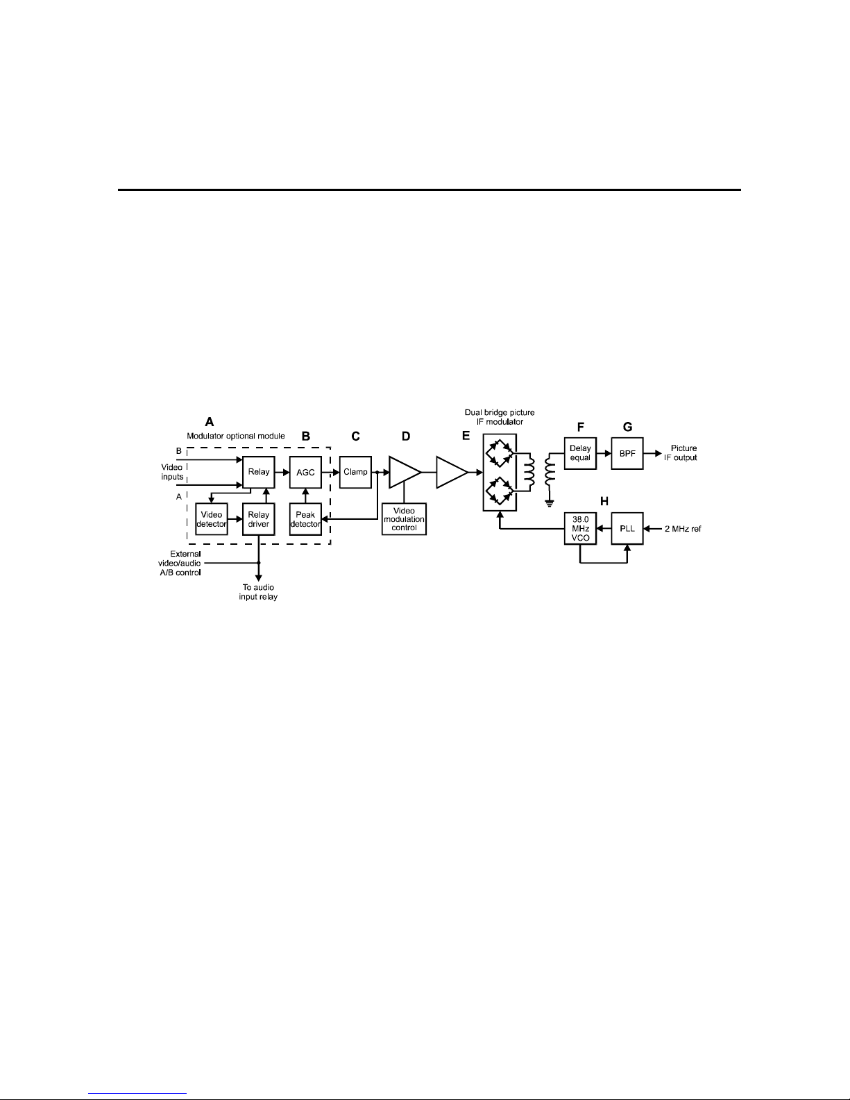
This section describes the operation of the C6M-II through a series of block diagrams. The text
is keyed to letters on the block diagrams.
Video to IF Modulation System
Figure 4-1
Video to IF modulation system
A If the modulator option board is installed, baseband video input switching is available. The video
switch includes a Video A level sensor which automatically switches to Video B when the Video A
signal level is low or absent. Audio input switching follows the video input selection. A rear panel
connection provides external control.
B Video AGC is provided with the modulator option board for use with varying video signal levels and
when switching between video sources at different levels.
C The video system is applied to a dc clamp circuit. The dc clamp can be disabled through the
menu.
D The clamped signal is applied to a variable gain stage to permit depth of modulation adjustment.
Video modulation is controlled through the video modulation entry on the main menu.
E A dual diode bridge circuit provides amplitude modulation.
F The modulated IF output is buffered and then applied to an all-pass delay equalizer which corrects
the total group delay response error generated by the C6M-II system.
G The signal is bandpass filtered to remove unwanted frequencies at the
rear panel.
H The unmodulated 45.75 MHz carrier is generated by a phase-locked loop which locks a voltage
controlled oscillator to an internal 2 MHz reference.
PIF OUT connector on the
C6M-II Installation Manual
Page 39
4-2 System Block Diagrams
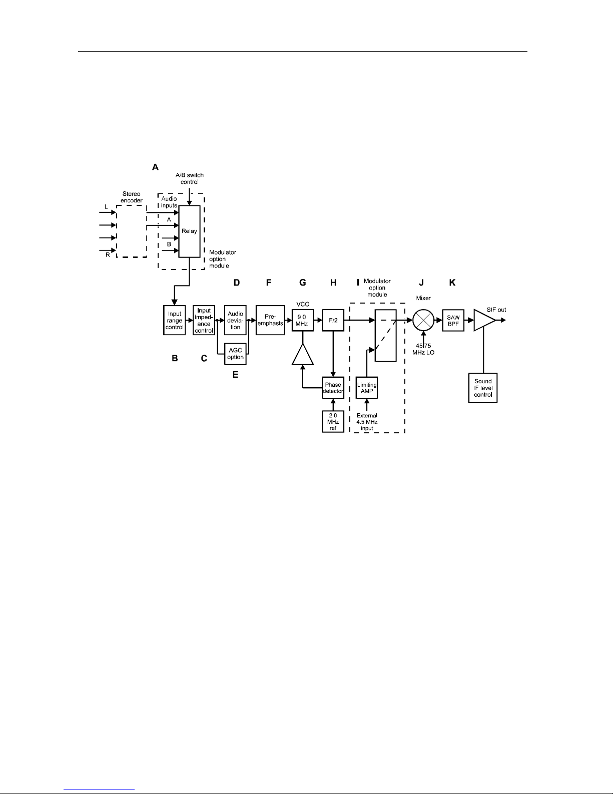
Audio to IF Modulation System
Figure 4-2
Audio to IF modulation system
A Left and right audio signals are encoded per BTSC standards when the stereo encoder option is
installed. If the modulator option board is installed, audio switching is provided. The audio input
will follow the switched video input.
B The audio input range is selected from the Audio range (AUDR) entry on the Audio menu. Either
the low range (AUDR LOW) which is –10 to +10 dBm, or the high range (AUDR HI) which is +5 to
+25 dBm, may be selected.
C The audio input impedance is selected from the Audio impedance (AUDZ) entry on the Audio
menu. Either low impedance (AUDZ LOW) which is 600 Ohms balanced, or high impedance
(AUDZ HI) which is 15 kohms, may be selected.
D A variable gain stage sets the FM deviation to the required ±25 kHz. This can be adjusted through
the Audio deviation entry on the Main menu.
E An optional AGC capability is provided for situations involving an unstable audio source or
switching between audio sources of different levels. This capability is enabled through the Audio
AGC entry on the Audio menu.
F The standard broadcast television pre-emphasis can be disabled.
G Frequency modulation is accomplished by applying the processed audio signal to a 9.0 MHz
voltage controlled oscillator (VCO). The center frequency of the sound carrier is precisely
maintained by a phase-locked loop with an internal 2.0 MHz reference.
H The audio VCO’s frequency is divided by two to produce the standard 4.5 MHz aural subcarrier
C6M-II Installation Manual
Page 40

System Block Diagrams 4-3
frequency.
I An optional external 4.5 MHz input switch is furnished to utilize a 4.5 MHz audio source.
J The subcarrier is mixed with the unmodulated 45.75 MHz signal to create the 41.25 MHz sound IF
frequency.
K The sound IF carrier is bandpass filtered and applied to an amplifier whose gain is controlled by
the A/V separation entry on the Main menu. This control sets the desired picture/sound carrier
level ratio.
C6M-II Installation Manual
Page 41

4-4 System Block Diagrams
IF Switching and AGC System
Figure 4-3
IF switching and AGC system
A The picture IF signal input is taken from the rear panel connectors. This signal is amplified to
compensate for the loss of the surface acoustic wave (SAW) filter that follows.
B This filter generates the required television vestigial sideband response shape and eliminates
unwanted frequencies.
C The sound IF signal input is taken from the rear panel connectors. A SAW bandpass filter removes
unwanted frequencies.
D The filtered IF signals are combined to produce a composite IF signal.
E The signal is split and buffered. One of the signals is a composite IF output while the other is fed to a
two-input IF relay switch. When not in use, the composite IF output should be terminated with
75 Ohms.
F The second input to the relay is normally from the
G After IF switching operations, the signal is applied to the Automatic IF Level Control (ALC)
subsystem. This circuit assures constant input level to the output converter system when switching
between IF signal sources that do not have equal level. The ALC function can be disabled when
required for processing non-standard signals.
H The composite IF signal is buffered and filtered to remove any spurious signals and delivered to the
IF-to-channel converter system input.
I A sample of that signal is provided at a front panel test point at 0 dBmV.
J With the option package installed, an additional relay is provided. The switch takes its two inputs
from the rear panel
relay switch.
AUX-IF and PRGM-IF inputs and delivers its output to the second input of the first
AUX-IF input connector.
C6M-II Installation Manual
Page 42
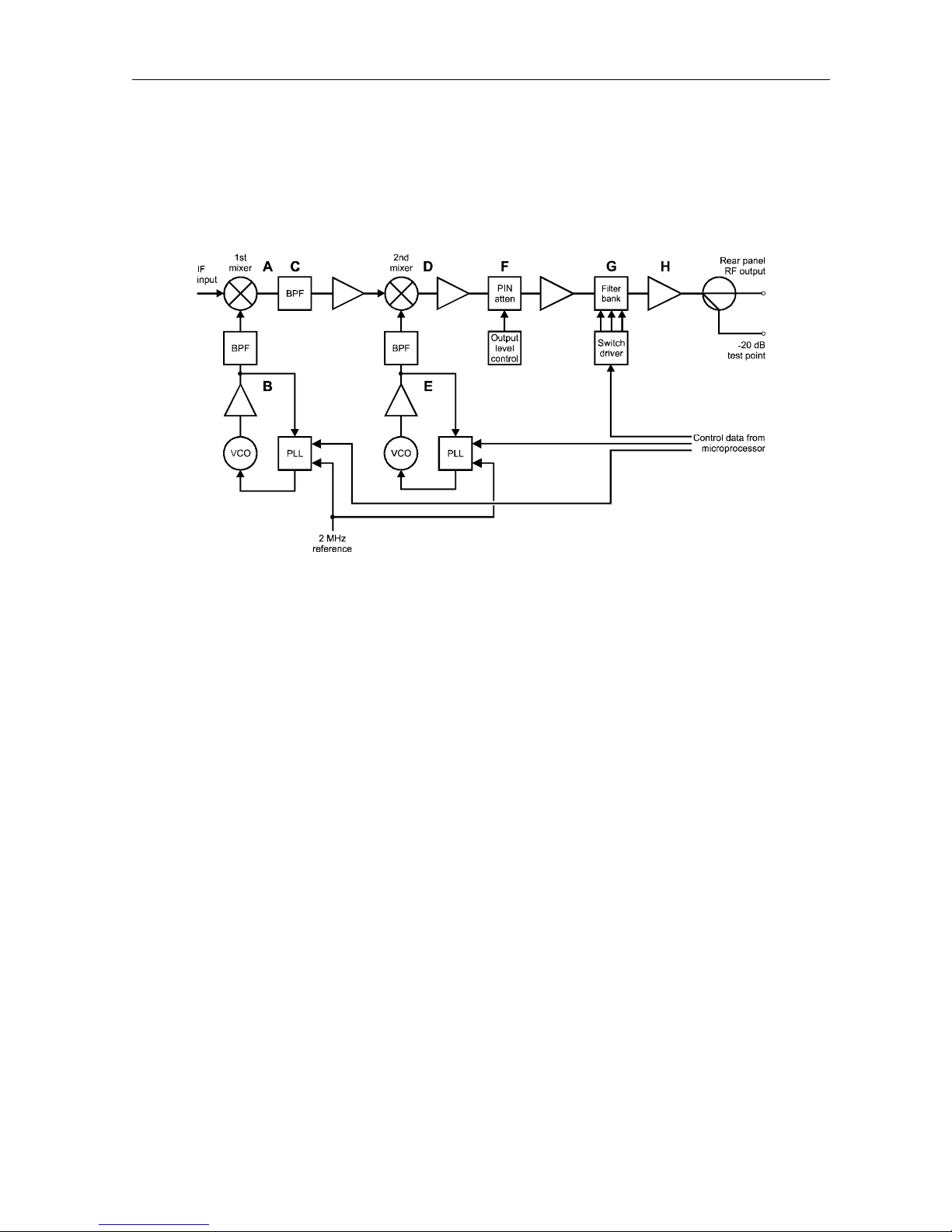
IF to Channel Converter System
Figure 4-4
IF to channel converter system
System Block Diagrams 4-5
A The IF input signal is applied to the first mixer.
B The local oscillator signal for the first mixer is generated by a voltage-controlled oscillator that is
PLL controlled. The PLL frequency is programmed by the microprocessor to accommodate the
selected channel plan or frequency setting.
C The local oscillator mixes with the IF input to produce the high IF which is then bandpass filtered
and amplified.
D The high IF is applied to the second mixer.
E The circuit for the second local oscillator must be tunable over a 1000 MHz range to produce RF
output picture carrier frequencies. The microprocessor programs the second LO PLL according to
the channel or frequency setting.
F The channel frequency output signal from the second mixer is applied to a variable loss PIN
attenuator. The circuit’s loss is controlled by the RF output level entry on the Main menu. This
permits trimming of the combined headend system carrier level for each channel.
G The signal is applied to the output bandpass filter bank. The appropriate filter is selected based
on the selected channel number. The filter system minimizes the broadband output noise and
allows unlimited broadband combining without need for external filters. The system maintains a
combined headend carrier-to-noise ratio of 60 dB. The RF output signal is supplied to the rear
panel while a sample at 20 dB below actual is brought to a front panel connector for monitoring the
final output signal.
H The RF signal is amplified by a wideband low distortion amplifier module to provide the 60 dBmV
specified picture carrier output level.
C6M-II Installation Manual
Page 43

Appendix A
Specifications
RF Output
Channels 2 to 161 (HRC, IRC, STD, EIA frequency plans or 12.5 kHz
steps)
Frequency Range 50 to 1000 MHz
Frequency Accuracy ±5 kHz maximum, ±500 Hz typical
Output Level +60 dBmV minimum
Recommended operating range 57 to 61 dBmV
Spurious –60 dBc minimum @ 60 dBmV (50 to 1000 MHz) with sound
carrier at −15 dBc
Output Return Loss 14 dB minimum within channel (50 to 750 MHz)
13 dB minimum within channel (750 to 1000 MHz)
Sound Carrier Level (adjustable) –10 to –20 dB relative to video carrier
C/N Ratio (normalized to 4 MHz)
In-band 68.0 dB minimum, 70.0 dB typical
Adjacent Channel 72.0 dB minimum, 74.0 dB typical
Wideband 75.5 dB minimum, 76.0 dB typical
IF
Picture IF Output Frequency 45.75 MHz
Picture IF Output Level 35 dBmV @ 87.5% modulation
Sound IF Output Frequency 41.25 MHz
Sound IF Output Level 15 to 25 dBmV
CW IF Output Frequency 45.75 MHz
CW IF Output Level 50 dBmV ±5 dB
Composite IF Output (picture IF level) 30 dBmV ±1 dB @ 87.5% modulation
Video
C6M-II Installation Manual
Page 44

A-2 Specifications
Standard Baseband Input 0.5 to 2.0 Vp-p for 87.5% modulation
Encoded Video Input Level 1.0 Vp-p for 87.5% modulation
Video Input Impedance 75 Ohms
Video Input Return Loss 30 dB minimum
K Factor 2% maximum
S/N Ratio (lum. weighted) 64 dB minimum
Chroma Delay, relative to standard
precorrection
Frequency Response ±0.5 dB from 0 to 4.1 MHz
Differential Gain ±3% @ 87.5% modulation
Differential Phase 1.0 degree p-p maximum @ 87.5% modulation
Tilt 1% maximum
±50 nsec
Audio
Input Level Range
Low –10 to +10 dBm, Z
High +5 to +25 dBm, Z
Input Impedance
Low 600 Ohms balanced
High 15 kOhms minimum
Frequency Response ±1.0 dB from 30 Hz to 15 kHz
Preemphasis 75 µsec, defeatable
Harmonic Distortion 1% maximum from 30 Hz to 15 kHz at ±25 kHz
= 600 Ohm
0
= 600 Ohm
0
Hum and Noise –60 dBc maximum with ±25 kHz
Subcarrier Frequency 4.5 MHz ±500 Hz
Subcarrier Input Level +35 to 45 dBmV
General
ac Voltage Requirements 100 to 240 Vrms, 50 to 60 Hz
Power Requirements 40 watts maximum
Operating Temperature 0 to 50° C
Weight 13.5 lbs maximum
Dimensions 19” W x 1.75” H x 17.5” D
C6M-II Installation Manual
Page 45
Appendix B
Frequency Plan
GI
Channel
Number
HRC IRC Standard EIA
2 54.0027 55.2625 55.2500 55.2500 2
3 60.0030 61.2625 61.2500 61.2500 3
4 66.0033 67.2625 67.2500 67.2500 4
5 78.0039 79.2625 77.2500 77.2500 5 A-7
6 84.0042 85.2625 83.2500 83.2500 6 A-6
7 174.0087 175.2625 175.2500 175.2500 7
8 180.0090 181.2625 181.2500 181.2500 8
9 186.0093 187.2625 187.2500 187.2500 9
10 192.0096 193.2625 193.2500 193.2500 10
11 198.0099 199.2625 199.2500 199.2500 11
12 204.0102 205.2625 205.2500 205.2500 12
13 210.0105 211.2625 211.2500 211.2500 13
14 120.0060 121.2625 121.2625 121.2625 14 A
Picture Carrier Frequency (MHz)
EIA
Channel
Historical
Reference
15 126.0063 127.2625 127.2625 127.2625 15 B
16 132.0066 133.2625 133.2625 133.2625 16 C
17 138.0069 139.2625 139.2500 139.2500 17 D
18 144.0072 145.2625 145.2500 145.2500 18 E
19 150.0075 151.2625 151.2500 151.2500 19 F
20 156.0078 157.2625 157.2500 157.2500 20 G
21 162.0081 163.2625 163.2500 163.2500 21 H
22 168.0084 169.2625 169.2500 169.2500 22 I
23 216.0108 217.2625 217.2500 217.2500 23 J
24 222.0111 223.2625 223.2500 223.2500 24 K
25 228.0114 229.2625 229.2625 229.2625 25 L
26 234.0117 235.2625 235.2625 235.2625 26 M
27 240.0120 241.2625 241.2625 241.2625 27 N
C6M-II Installation Manual
Page 46
B-2 Frequency Plan
GI
Channel
Number
HRC IRC Standard EIA
28 246.0123 247.2625 247.2625 247.2625 28 O
29 252.0126 253.2625 253.2625 253.2625 29 P
30 258.0129 259.2625 259.2625 259.2625 30 Q
31 264.0132 265.2625 265.2625 265.2625 31 R
32 270.0135 271.2625 271.2625 271.2625 32 S
33 276.0138 277.2625 277.2625 277.2625 33 T
34 282.0141 283.2625 283.2625 283.2625 34 U
35 288.1440 289.2625 289.2625 289.2625 35 V
36 294.0147 295.2625 295.2625 295.2625 36 W
37 300.0150 301.2625 301.2625 301.2625 37 X
38 306.0153 307.2625 307.2625 307.2625 38 Y
39 312.0156 313.2625 313.2625 313.2625 39 Z
40 318.0159 319.2625 319.2625 319.2625 40 DD
Picture Carrier Frequency (MHz)
EIA
Channel
Historical
Reference
41 324.0162 325.2625 325.2625 325.2625 41 EE
42 330.0165 331.2750 331.2750 331.2750 42 FF
43 336.0168 337.2625 337.2625 337.2625 43 GG
44 342.0171 343.2625 343.2625 343.2625 44 HH
45 348.0174 349.2625 349.2625 349.2625 45 II
46 354.0177 355.2625 355.2625 355.2625 46 JJ
47 360.0180 361.2625 361.2625 361.2625 47 KK
48 366.0183 367.2625 367.2625 367.2625 48 LL
49 372.0186 373.2625 373.2625 373.2625 49 MM
50 378.0189 379.2625 379.2625 379.2625 50 NN
51 384.0192 385.2625 385.2625 385.2625 51 OO
52 390.0195 391.2625 391.2625 391.2625 52 PP
53 396.0198 397.2625 397.2625 397.2625 53 QQ
54 72.0036 73.2625 73.2500
55 78.0039 79.2625 79.2500
56 84.0042 85.2625 85.2500
57 90.0045 91.2625 91.2500 91.2500 95 A-5
58 96.0048 97.2625 97.2500 97.2500 96 A-4
C6M-II Installation Manual
Page 47
Frequency Plan B-3
GI
Channel
Number
HRC IRC Standard EIA
59 102.0051 103.2625 103.2500 103.2500 97 A-3
60 108.0054 109.2750 109.2750 109.2750 98 A-2
61 114.0057 115.2750 115.2750 115.2750 99 A-1
62 402.0201 403.2625 403.2500 403.2500 54 RR
63 408.0204 409.2625 409.2500 409.2500 55 SS
64 414.0207 415.2625 415.2500 415.2500 56 TT
65 420.0210 421.2625 421.2500 421.2500 57 UU
66 426.0213 427.2625 427.2500 427.2500 58 VV
67 432.0216 433.2625 433.2500 433.2500 59 WW
68 438.0219 439.2625 439.2500 439.2500 60 XX
69 444.0222 445.2625 445.2500 445.2500 61 YY
70 450.0225 451.2625 451.2500 451.2500 62 ZZ
71 456.0228 457.2625 457.2500 457.2500 63
Picture Carrier Frequency (MHz)
EIA
Channel
Historical
Reference
72 462.0231 463.2625 463.2500 463.2500 64
73 468.0234 469.2625 469.2500 469.2500 65
74 474.0237 475.2625 475.2500 475.2500 66
75 480.0240 481.2625 481.2500 481.2500 67
76 486.0243 487.2625 487.2500 487.2500 68
77 492.0246 493.2625 493.2500 493.2500 69
78 498.0249 499.2625 499.2500 499.2500 70
79 504.0252 505.2625 505.2500 505.2500 71
80 510.0255 511.2625 511.2500 511.2500 72
81 516.0258 517.2625 517.2500 517.2500 73
82 522.0261 523.2625 523.2500 523.2500 74
83 528.0264 529.2625 529.2500 529.2500 75
84 534.0267 535.2625 535.2500 535.2500 76
85 540.0270 541.2625 541.2500 541.2500 77
86 546.0273 547.2625 547.2500 547.2500 78
87 552.0276 553.2625 553.2500 553.2500 79
88 558.0279 559.2625 559.2500 559.2500 80
89 564.0282 565.2625 565.2500 565.2500 81
C6M-II Installation Manual
Page 48

B-4 Frequency Plan
GI
Channel
Number
HRC IRC Standard EIA
90 570.0285 571.2625 571.2500 571.2500 82
91 576.0288 577.2625 577.2500 577.2500 83
92 582.0291 583.2625 583.2500 583.2500 84
93 588.0294 589.2625 589.2500 589.2500 85
94 594.0297 595.2625 595.2500 595.2500 86
95 600.0300 601.2625 601.2500 601.2500 87
96 606.0303 607.2625 607.2500 607.2500 88
97 612.0306 613.2625 613.2500 613.2500 89
98 618.0309 619.2625 619.2500 619.2500 90
99 624.0312 625.2625 625.2500 625.2500 91
100 630.0315 631.2625 631.2500 631.2500 92
101 636.0318 637.2625 637.2500 637.2500 93
102 642.0321 643.2625 643.2500 643.2500 94
Picture Carrier Frequency (MHz)
EIA
Channel
Historical
Reference
103 648.0324 649.2625 649.2500 649.2500 100
104 654.0327 655.2625 655.2500 655.2500 101
105 660.0330 661.2625 661.2500 661.2500 102
106 666.0333 667.2625 667.2500 667.2500 103
107 672.0336 673.2625 673.2500 673.2500 104
108 678.0339 679.2625 679.2500 679.2500 105
109 684.0342 685.2625 685.2500 685.2500 106
110 690.0345 691.2625 691.2500 691.2500 107
111 696.0348 697.2625 697.2500 697.2500 108
112 702.0351 703.2625 703.2500 703.2500 109
113 708.0354 709.2625 709.2500 709.2500 110
114 714.0357 715.2625 715.2500 715.2500 111
115 720.0360 721.2625 721.2500 721.2500 112
116 726.0363 727.2625 727.2500 727.2500 113
117 732.0366 733.2625 733.2500 733.2500 114
118 738.0369 739.2625 739.2500 739.2500 115
119 744.0372 745.2625 745.2500 745.2500 116
120 750.0375 751.2625 751.2500 751.2500 117
C6M-II Installation Manual
Page 49

Frequency Plan B-5
GI
Channel
Number
HRC IRC Standard EIA
121 756.0378 757.2625 757.2500 757.2500 118
122 762.0381 763.2625 763.2500 763.2500 119
123 768.0384 769.2625 769.2500 769.2500 120
124 774.0387 775.2625 775.2500 775.2500 121
125 780.0390 781.2625 781.2500 781.2500 122
126 786.0393 787.2625 787.2500 787.2500 123
127 792.0396 793.2625 793.2500 793.2500 124
128 798.0399 799.2625 799.2500 799.2500 125
129 804.0402 805.2625 805.2500 805.2500 126
130 810.0405 811.2625 811.2500 811.2500 127
131 816.0408 817.2625 817.2500 817.2500 128
132 822.0411 823.2625 823.2500 823.2500 129
133 828.0414 829.2625 829.2500 829.2500 130
Picture Carrier Frequency (MHz)
EIA
Channel
Historical
Reference
134 834.0417 835.2625 835.2500 835.2500 131
135 840.0420 841.2625 841.2500 841.2500 132
136 846.0423 847.2625 847.2500 847.2500 133
137 852.0426 853.2625 853.2500 853.2500 134
138 858.0429 859.2625 859.2500 859.2500 135
139 864.0432 865.2625 865.2500 865.2500 136
140 870.0435 871.2625 871.2500 871.2500 137
141 876.0438 877.2625 877.2500 877.2500 138
142 882.0441 883.2625 883.2500 883.2500 139
143 888.0444 889.2625 889.2500 889.2500 140
144 894.0447 895.2625 895.2500 895.2500 141
145 900.0450 901.2625 901.2500 901.2500 142
146 906.0453 907.2625 907.2500 907.2500 143
147 912.0456 913.2625 913.2500 913.2500 144
148 918.0459 919.2625 919.2500 919.2500 145
149 924.0462 925.2625 925.2500 925.2500 146
150 930.0465 931.2625 931.2500 931.2500 147
151 936.0468 937.2625 937.2500 937.2500 148
C6M-II Installation Manual
Page 50

B-6 Frequency Plan
GI
Channel
Number
HRC IRC Standard EIA
152 942.0471 943.2625 943.2500 943.2500 149
153 948.0474 949.2625 949.2500 949.2500 150
154 954.0477 955.2625 955.2500 955.2500 151
155 960.0480 961.2625 961.2500 961.2500 152
156 966.0483 967.2625 967.2500 967.2500 153
157 972.0486 973.2625 973.2500 973.2500 154
158 978.0489 979.2625 979.2500 979.2500 155
159 984.0492 985.2625 985.2500 985.2500 156
160 990.0495 991.2625 991.2500 991.2500 157
161 996.0498 997.2625 997.2500 997.2500 158
Picture Carrier Frequency (MHz)
EIA
Channel
Historical
Reference
C6M-II Installation Manual
Page 51
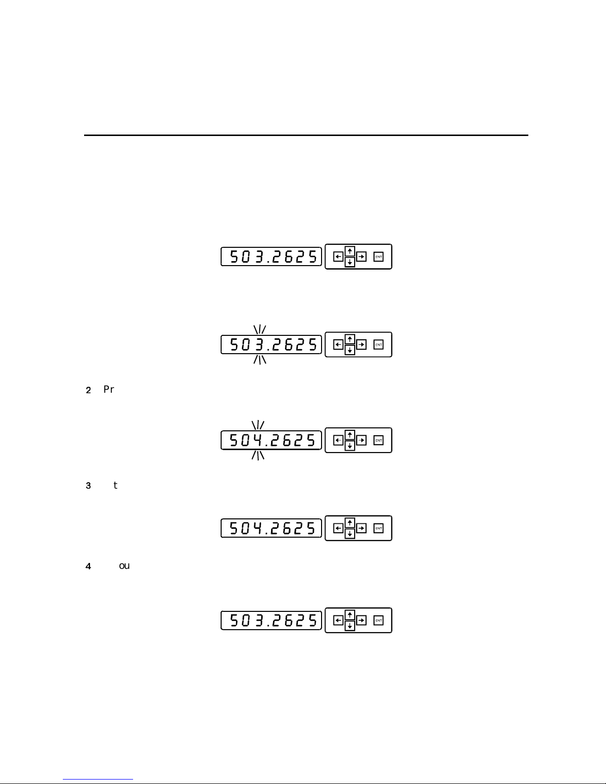
Appendix C
Changing a Menu Item
The following example illustrates how to change the frequency.
Display the frequency on the Main menu as described in Section 2, Overview. The illustration
below shows the frequency 503.2625.
1 Press the right arrow key. In this case, the digit “3” flashes as shown below.
Press the up arrow key. The digit “4” appears and flashes as shown below.
If this is the change you want, press the ENT key to implement the change.
If you decide not to make the change, do not press ENT. The frequency will return to the
previous value after a short delay.
C6M-II Installation Manual
Page 52

C-2 Changing a Menu Item
If you wish to return to the previous value immediately, press the left arrow key until the
previous value appears. In this case the left arrow key is pressed three times, and, as
shown below, the “0” flashes, the “5” flashes, and then the previous value appears.
A summary:
To reach any item in a menu Use the up or down arrow key (menu wraps vertically).
To get into a submenu (e.g., Option) Use the right arrow key.
To get out of a submenu Use the left arrow key.
To change a menu item Use the right arrow key to cause the item to flash. Use the up
or down arrow key until the desired value or function is
reached. Press the
left arrow key to exit the menu. If no change is made, the
value reverts to the previous setting.
ENT key to implement a change. Use the
C6M-II Installation Manual
Page 53
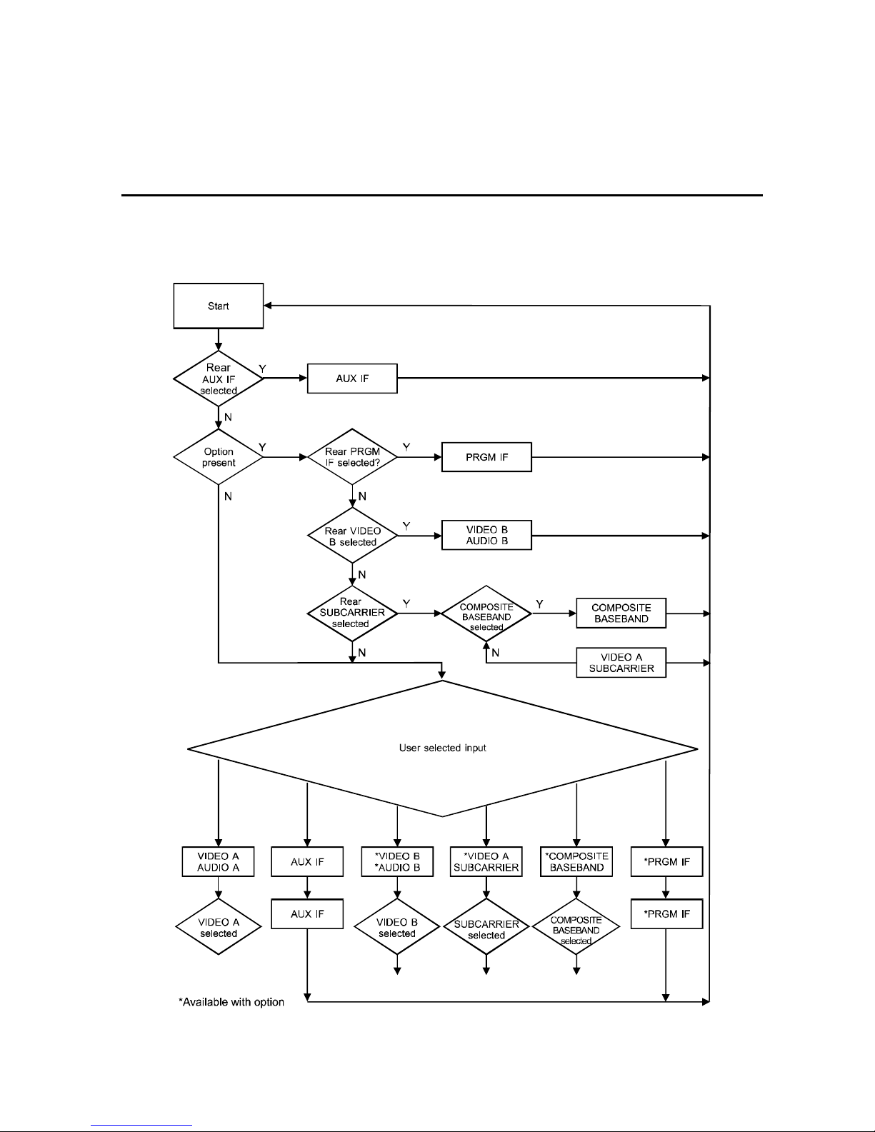
Appendix D
Signal Priority Chart
C6M-II Installation Manual
Page 54
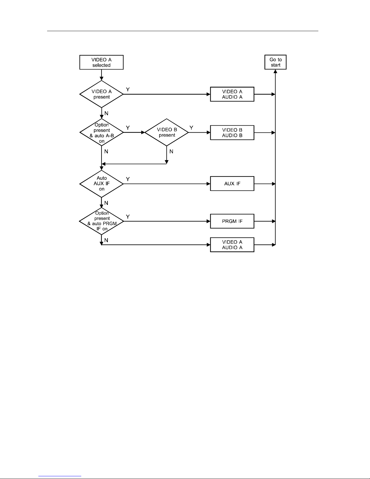
D-2 Signal Priority Chart
C6M-II Installation Manual
Page 55
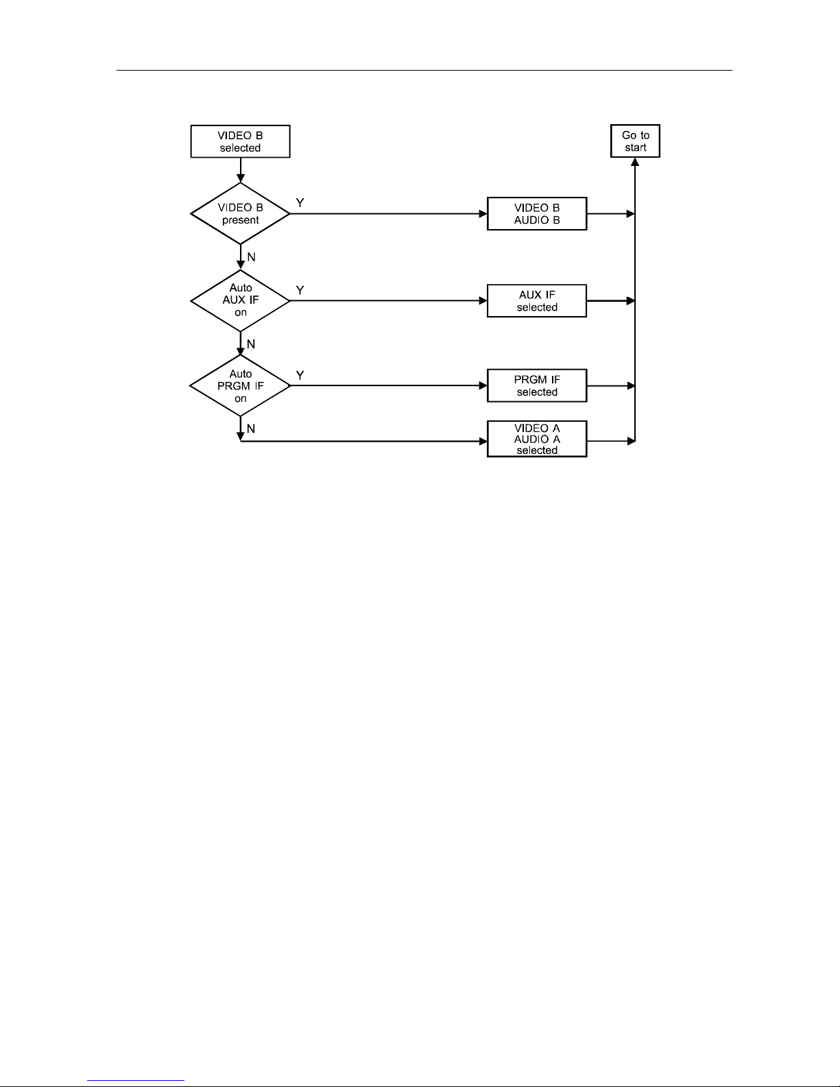
Signal Priority Chart D-3
C6M-II Installation Manual
Page 56
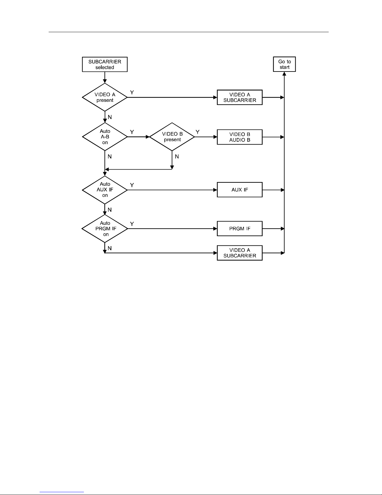
D-4 Signal Priority Chart
C6M-II Installation Manual
Page 57
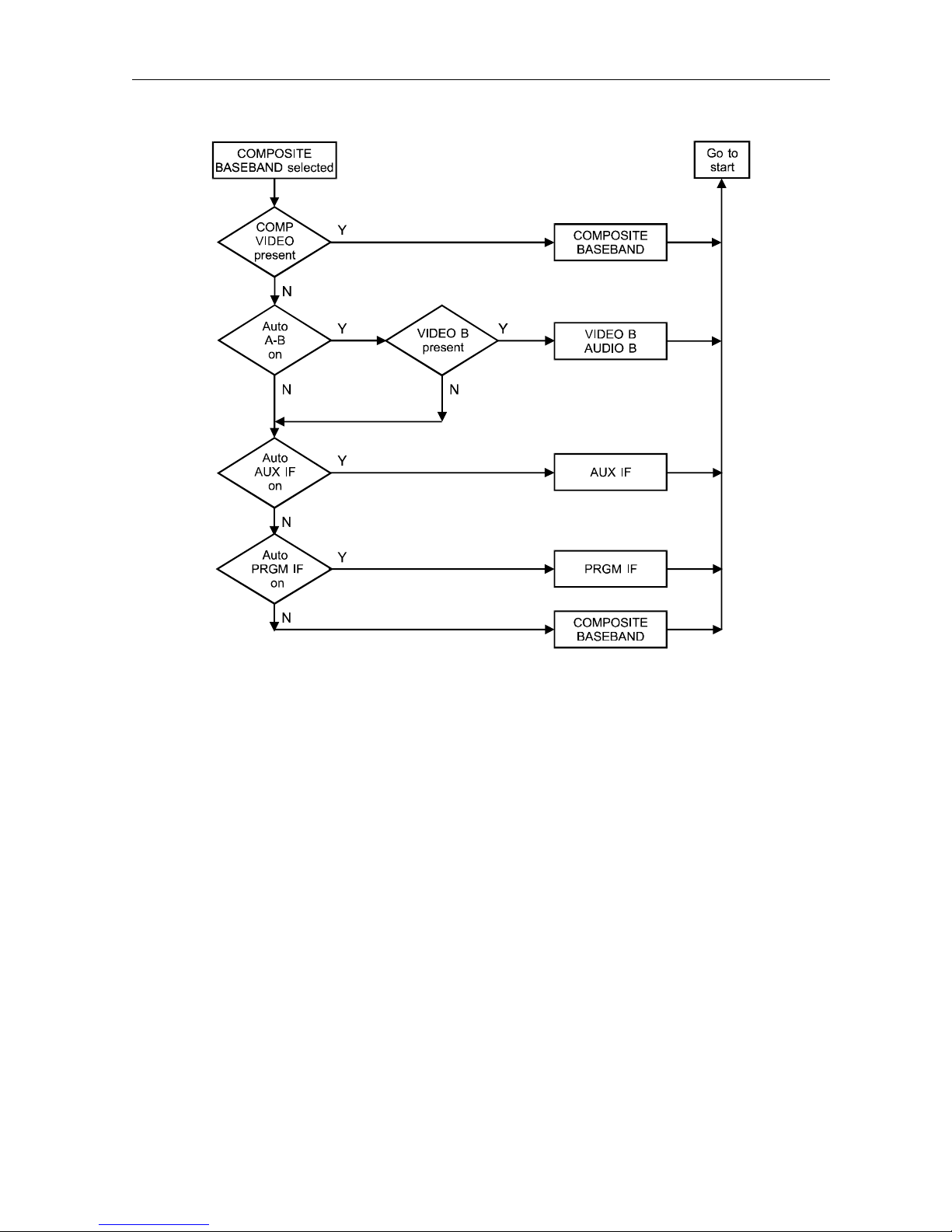
Signal Priority Chart D-5
C6M-II Installation Manual
Page 58
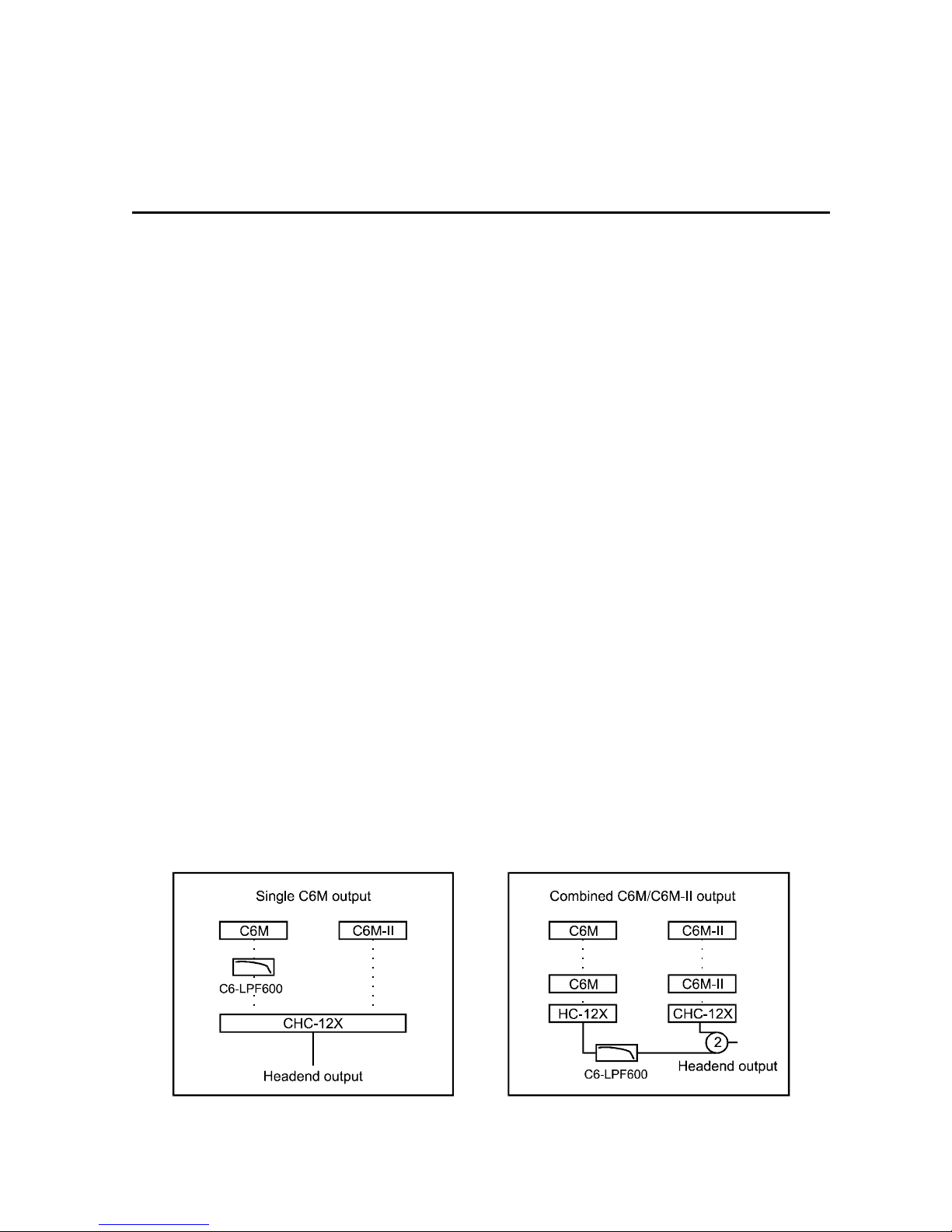
Appendix E
Application Notes
C6-LPF600
This application note is to assist you in the operation of the C6M in headends operating above
600 MHz.
Summary
The C6M incorporates a dual high IF conversion technique that minimizes spurious and
distortion products within the 50 to 600 MHz operating bandwidth of the C6M. The high IF
local oscillator, which is used to downconvert the high IF to the desired output RF carriers,
operates above 600 MHz. This local oscillator frequency may be present at the C6M RF output
and may cause interference with analog and digital channels, or data carriers operating above
600 MHz.
To minimize this potential problem, install a C6-LPF600. The C6-LPF600 is a high
performance, low-pass filter (10 to 600 MHz) that may be used to attenuate spurious carriers
occurring at 600 MHz and above frequencies. The specifications on this filter are included with
this application note.
Discussion
The C6-LPF600 (GI Part No. 928-363-000) is installed either at the RF output of the C6M, or
may be installed at the C6M RF combined output before the insertion of channels operating
above 600 MHz.
Typical installations with the C6M and the C6M-II are displayed below.
Figure E-1
Typical installations of C6-LPF600
C6M-II Installation Manual
Page 59

E-2 Application Notes
Specifications
Passband Stopband
Bandwidth 10 to 600 MHz 600 to 1000 MHz
Insertion Loss 2.0 dB maximum –40 dB minimum @ 673 MHz
Return Loss –14 dB minimum N/A
C6M-II Installation Manual
Page 60

General Instrument Corporation
GI Communications Division
Printed in U.S.A.
410515-001-99, 3/97
 Loading...