

Page 1
General Filters
Incorporated
16 | P a g e
4. START-UP
1. Before starting, check that there are no water leaks and that the electrical components are dry.
2. DO NOT connect power if the humidifier is damaged or even partially wet!
When installation is completed, flush the supply pipe for 10 minutes by piping water directly into the drain without sending it into the
humidifier. This will eliminate any scale or residue that may cause foam when boiling.
4.1 Start-Up Checklist
Before starting the humidifier, the following should be checked:
• Water is connected, the line has been flushed, and external valves are open.
• Min 1-1/2” ID drain is installed, but not connected to 90° elbow (supplied), run to an open drain, and has a trap under the unit.
• Electricity is connected in accordance with instructions, local codes and data labels in the unit.
• The 25 or 30A power fuses are installed and intact.
• All AWG10 control wiring is done and tested.
• The airflow switch is wired to open on air flow loss.
• The Hi-limit humidistat is wired to open on humidity rise above set point.
• Remove two screws securing control board. Unit wires should be checked to make sure they and all connectors are tight.
• The steam hose(s) are run correctly with no sags or kinks and sloped properly according to the manual.
• Condensate hose(s) are run correctly with no sags or kinks and sloped properly according to the manual.
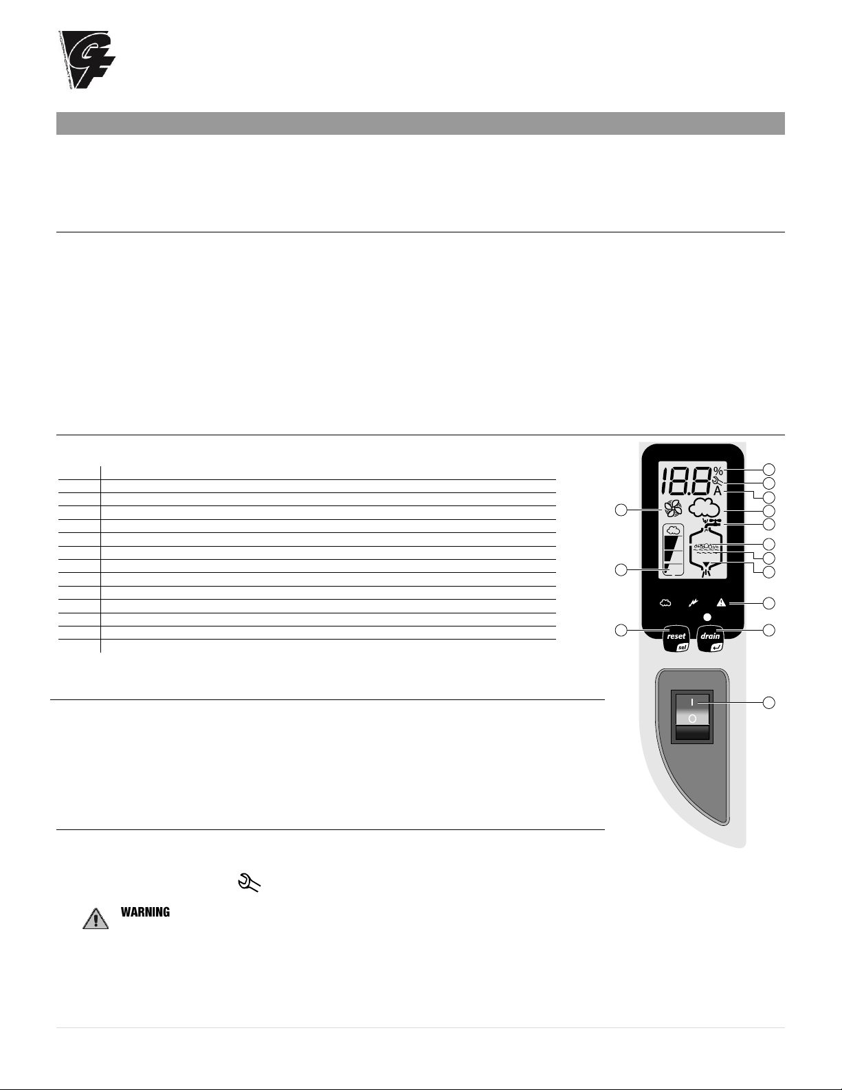
4.2 The Elite Steam Humidifier Controller
The Elite Steam Humidifier Controller features a comprehensive information display that shows the
operation of the system at a glance:
1.
Display is % of nominal capacity
2.
Maintenance
3.
Display is amperage (default)
4.
Steam is being produced
5.
Cylinder filling
6.
Foaming
7.
Water presence inside the cylinder
8.
Cylinder draining
9.
LED’s indicate: power (yellow), operation (green) and alarms (red)
10.
Drain button for manual draining of cylinder and confirming parameter values
11.
ON/OFF button
12.
Reset button to reset alarms and access parameters
13.
Level of output: 33%, 66%, 100%
14.
Fan relay is activated (when fan icon on the control module is stationary, not flashing)
The Elite Steam Humidifier is now ready to operate.
4.3 Starting the Elite Steam Humidifier
• Insure that the external power is turned on.
• Push the top part of the ON/OFF button so that the “I” part is in (See #11 at right). The yellow
power LED will be lit. The Elite Steam Humidifier is now ready to operate.
• When there is a call for humidity, the Elite Steam Humidifier will close its power relays and send
power to the electrodes in the plastic steam generator. The green Operation LED will light,
indicating that operation has begun.
4.4 Starting With A New Steam System or Replacement Steam Cylinder
When starting with a new cylinder, you should activate the cylinder cleaning function as follows:
1. Switch the Elite Steam Humidifier off.
2. Press and hold both buttons, “reset” and “drain”, and switch the Elite Steam Humidifier back on. When the wrench blinks
then release the two buttons.
3. Press and hold “reset” until the display shows 04.
: DO NOT confirm any value higher than 04. If 05 or higher is displayed, press “reset” until the display goes
back to the normal operating mode and restart from step 1.
4. Press “drain” (minimum 1 second): the cleaning starts and the display shows PC.
1
2
4
5
6
9
1012
13
14
11
3
7
8
Page 2
General Filters
Incorporated
17 | P a g e
During the cleaning, the electrodes are powered and water in the cylinder rises until it touches the high-level sensor or the phase current equals
20A, whichever occurs first. After either of the events is detected, the boiler is fully discharged with the electrodes un-powered (the drain pump
and the drain tempering valve are activated for 3 minutes). General Filters, Inc. recommends performing two cleanings when starting a new
boiler. After the cleaning ends, the humidifier begins its regular function. When starting the unit with a new or empty cylinder, it may take a
significant amount of time (hours) for the unit to build up enough mineral concentration to reach rated capacity. This time can be shortened by
the addition of a teaspoon of salt or ¼ of an antacid tablet through the steam outlet on top of the cylinder.
5. Operating the Elite Steam Humidifier
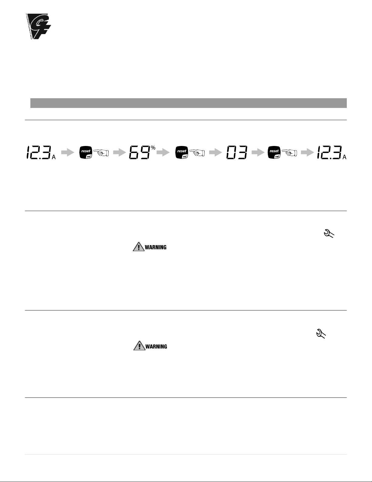
5.1 Displaying Information
By pressing the “reset” button for 2 seconds, the display will loop from amperage to production in % of the maximum production to
the hour counter and back to amperage:
Figure 5.a
1. Amperage: it is the value of the current that flows through the water, causing it to boil (default display).
2. Production %: it is the current production expressed as a percentage of the humidifier’s capacity.
3. Hour counter: expressed in tens; for instance, when the display shows 13 the real hour value will be between 130 and 139
hours.
5.2. Select Signal Type
The Elite Steam Humidifier is pre-set for the included GFX3 humidistat (signal type 0). If the included humidistat is used, this section
may be omitted. If another humidistat is used, review this section to see if changes are needed.
1. Switch Elite Steam Humidifier off.
2. Press and hold both buttons “reset” and “drain” and switch the Elite Steam Humidifier back on. When the wrench blinks,
release the two buttons.
3. Press “Reset” until the display shows 02. : DO NOT confirm any value higher than 04. If 05 or higher is
displayed, press “Reset” until the display goes back to the normal operating mode and restart from step 1.
4. Press “drain” (minimum 1 second) to confirm: the display shows “P1” then the current signal type and “set”.
5. Press “Reset” to change signal type between 0 and 1:
0 = On-Off humidistat such as the GeneralAire “M” or “GFX” series humidistat.
1 = external 0...10 Vdc modulating signal such as the GeneralAire® ADCD series humidistat.
6. Press “drain” (minimum 1 second) when done to confirm the new value of P1 and exit to the normal operating mode.
7. Switch Elite Steam Humidifier off: you can now proceed with connecting the control wiring.
5.3. Changing the Maximum Production
The Maximum Production feature can be adjusted between 20% to 100% of the nominal production in steps of 5% in order to suit
the environmental characteristics. DS25 Maximum production is factory set at 70%.
1. Switch Elite Steam Humidifier off.
2. Press both and hold both buttons “Reset” and “Drain” and switch Elite Steam Humidifier back on. When the wrench blinks;
release the two buttons.
3. Press “reset” until the display shows 01. : DO NOT confirm any value higher than 04. If 05 or higher is
displayed, press "reset" until the display goes back to the normal operating mode and restart from step 1.
4. Press “drain” (minimum 1 second) the display shows “P0” then the current Maximum Production Percent and “set”.
5. Press “reset” to change the Maximum Production in steps of 5% between 20% and 100%.
6. Press and hold “drain” (minimum 1 second) when done to confirm the new Maximum Production and exit to the normal
operating mode.
5.4 Activating Manual Drain
Press and hold the “drain” button on the front of the unit until the cylinder is drained. Note: Water will continue to flow from the
tempering valve after the cylinder is empty.
Page 3
General Filters
Incorporated
18 | P a g e
5.5 Resetting the Hour Counter With Each New Replacement Cylinder
The hour counter should be reset every time the cylinder is changed in order to reset and restart the internal maintenance timer:
1. Switch the Elite Steam Humidifier off.
2. Press and hold both buttons “Reset” and “Drain” and switch the Elite Steam Humidifier back on. When the wrench blinks;
release buttons.
3. Press and hold “reset” until the display shows 03. : DO NOT confirm any value higher than 04. If 05 or higher is
displayed, press “reset” until the display goes back to the normal operating mode and restart from step 1.
4. Press “drain” (minimum 1 second) to confirm: the hour counter will be reset at once and the Elite Steam Humidifier will go back
to the normal operating mode.
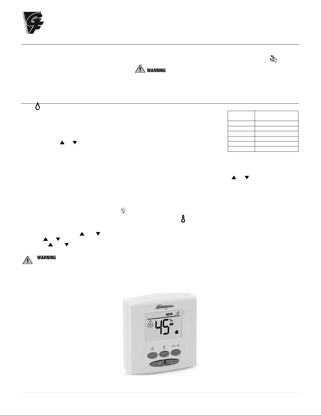
5.6 Using the GFX3 Humidistat
Press to select OFF, AUTO (if outdoor sensor is connected) or MANUAL mode.
OFF mode:
The humidifier is turned off.
MANUAL mode:
The GFX3 will work to maintain the single humidity selected. You can set your desired humidity
level by pressing or . The humidifier will turn ON or OFF according to your manual setting.
(The humidifier will operate when the measured relative humidity falls more than 2% below the set
point.) Humidity will have to be lowered when weather is colder or if condensation is suspected.
AUTO mode:
The GFX3 will automatically raise the humidity as the outdoor temperature increases. This provides the highest possible humidity.
The GFX3 will automatically lower the humidity as temperatures drop. This minimizes the risk of condensation on cold surfaces like
windows. You can adjust the Auto Humidity Index Set Point from 0 (low) to 10 (high) by pressing or . The Humidity Index is
based on the outdoor temperature and indoor humidity. The humidifier will switch ON/OFF according to the calculated auto humidity
index set point. Lower Index settings are for older homes with less insulation and vapor barriers. Higher Index settings are for newer
homes with complete vapor barriers, triple pane windows and high R value insulation. If condensation occurs reduce Index setting by
2 points until condensation stops.
NOTE If the outdoor temperature sensor fails, flashes and the unit will default to MANUAL mode.
To toggle between indoor / outdoor temperature and indoor humidity: Press .
To change the temperature unit: Press °C / °F.
To set the temperature / humidity offset in MANUAL or AUTO mode:
1. Simultaneously press and when viewing the temperature or humidity reading.
2. Use or to change the setting (-3 to 3).
3. Press and simultaneously or wait 5 seconds to confirm, then move onto the next setting.
: DO NOT allow excess humidification.
Excess humidity can cause condensation and enable mold and mildew growth.
Suggested
Setting
Outdoor
Temperatures
15%
-20˚F / -29˚C
20%
-10˚F / -23˚C
25%
0˚F / -18˚C
30%
+10˚F / -12˚C
35%
+20˚F / -7˚C
40%
+30˚F / -1˚C
Table 5.a
GFX3 HUMIDISTAT
Page 4
General Filters
Incorporated
19 | P a g e
5.7 Alarms
In the event of an alarm, the red alarm LED will flash, the alarm relay will close, and the alarm code will flash in the display. Multiple
alarms will flash in sequence, alternating with the main display. Pressing the “reset/sel” button for 2 seconds will reset the alarms,
although still active alarms will continue to display.
Dis
play
Description
Action
Red
Led
Alarm
Relay
Notes
--
Remote on-off open
Unit disabled
Off
Off EE
Internal memory error
Unit disabled
On
On
E0
Control board configuration not valid
Unit disabled
On
On
Turn off, check control board,
reprogram
E1
High current alarm
Unit disabled
On
On
Turn off, check connections, check
cylinder (no limescale bridges
between electrodes, no electrodes
short-circuited)
E2
Low production, low supply water
conductivity or excessive
foam/limescale in the cylinder
Unit disabled
Press “reset/sel” key for 1 second to reset
On
On
Check supply water conductivity
(too low?), replace the cylinder.
E3
Cylinder almost exhausted
Press “reset/sel” key for 1 second to reset
Off
Off
Change cylinder (not urgent)
E4
Fill alarm, unable or slow fill
(current does not increase within
timeout)
Press “reset/sel” key for 1 second to reset,
otherwise the warning will be reset
automatically every 10 minutes until the
supply water is available again
On
On
Check water supply and fill valve;
check drain pump for leakage
E5
Drain alarm, unable to drain
(current does not decrease within
timeout)
Press “reset/sel” key for 1 second to reset
On
On
Check drain pump and drain
connection
E6
Cylinder exhausted
(critical performance detected)
The warning is automatically reset if the Elite
Steam Humidifier can produce the demand,
otherwise turn off and then on
Off
Off
Change cylinder (urgent)
E7
Foam detected
Press “reset/sel” key for 1 second to reset
Off
Off
If foam continues, perform
additional cleaning cycles (read
chap. “Starting With A New Steam
System or Replacement Steam
Cylinder”)
E8
Cylinder lifetime expired
Unit disabled: reset the hour counter (read
chap. “Resetting the Hour Counter”)
On
On
Change the cylinder if necessary
E9
High controller temperature (above
176°F / 80°C)
The warning is automatically reset if the
temperature decreases below 176 °F / 80 °C
Off
Off
Check the ambient temperature,
replace the controller
Page 5

General Filters
Incorporated
20 | P a g e
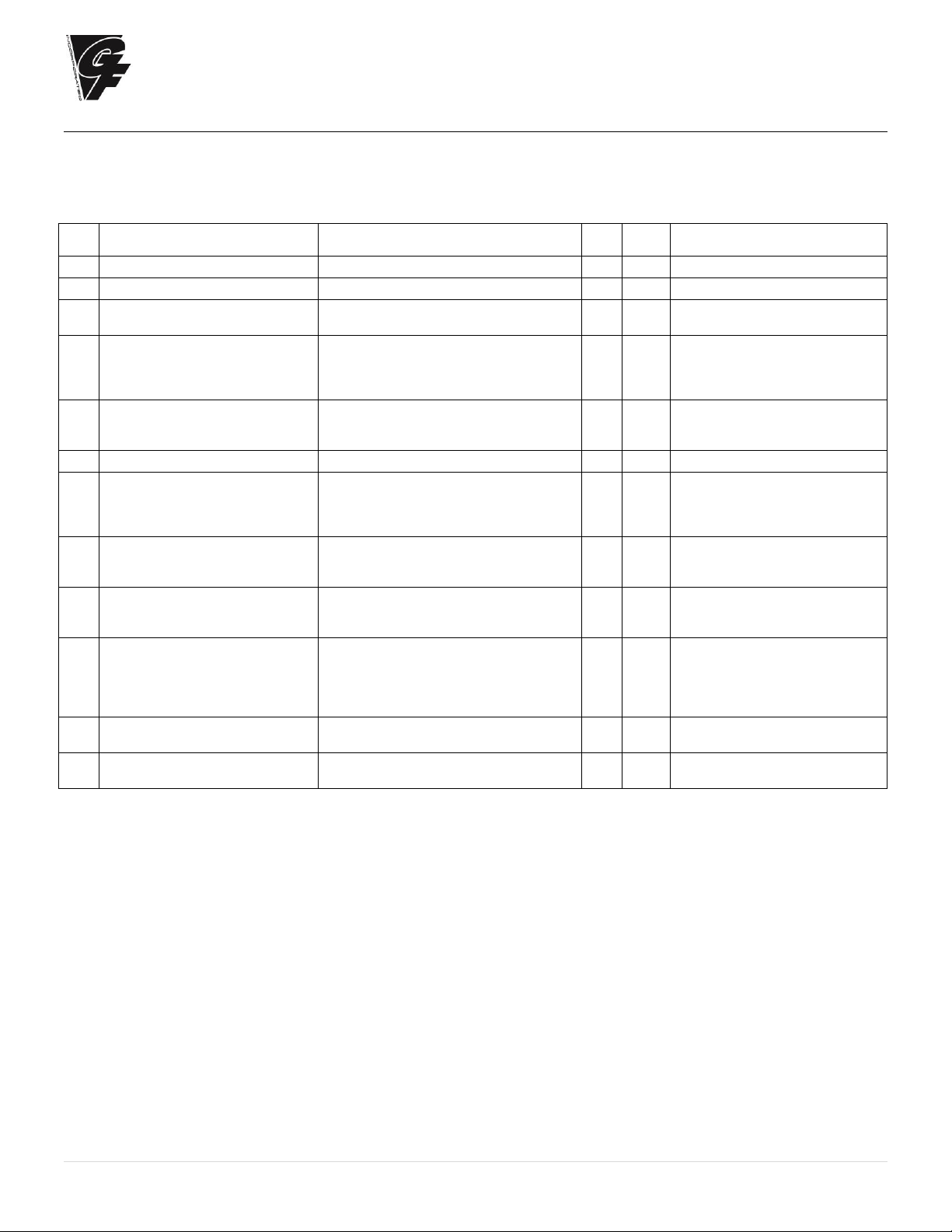
6. TROUBLE SHOOTING
Table 6.a
Problem
Causes
Solutions
The humidifier does not turn
on
1. No electrical power
2. ON/OFF switch of the humidifier in position 0
(open)
3. Control connectors improperly connected
4. Blown fuses
5. Transformer failure
1. Check the safety devices upstream from the humidifier
and the presence of power
2. Close the switch on the panel: position I
3. Check that connectors are properly inserted in terminal
block
4. Check the condition of fuses
5. Check that the proper voltage is connected and turned
on
The humidifier does not start
operation
1. Remote ON/OFF contact open
2. The humidistat has not been connected
correctly
3. Humidistat failure
4. Control signal not compatible with the type set
5. Value measured by the sensor/s higher than
the corresponding set point
6. Fan relay not activated, or furnace blower not
activated or connected to C/NO on steam
humidifier
1. Close ON/OFF contacts
2. Check the external connection
3. Replace the humidistat
4. Check furnace fan / blower operation
The humidifier fills with water
without producing steam
1. High steam back pressure
2. Fill valve strainer clogged
3. Mineral in the fill cup
4. Drain pump valve leaking
1. Check that the steam hose is not kinked or sagging,
trapping condensate
2. Clean the fill valve strainer
3. Clean the fill cup
4. Check for voltage at the drain pump valve and/or drain
pump replacement
Excess humidity or moisture
in the duct
1. The distributor is not installed correctly (too
near the top of the duct or the condensate
return is blocked)
2. Air flow rate is too low
3. Humidifier active when the fan in the duct is off
1. Check that the steam distributor is installed correctly
2. Increase air flow in duct or decrease PO maximum steam
production setting
3. Check the connection of the device (flow switch or
differential pressure switch) controlling the humidifier to
the ventilation in the duct
Water leaks on to the floor
below
1. The humidifier drain is blocked
2. The supply water or overflow circuit has leaks
3. The condensate drain pipe does not bring the
water back to the drain pan
4. The steam hose is not properly fastened to the
cylinder
5. The bushing and / or O-ring at the base of the
cylinder are missing or not properly seated
1. Clean the drain assembly and pan
2. Check the entire water circuit
3. Check the correct position of the condensate drain hose
in the drain pan
4. Check the fastening of the hose clamps on the steam
outlet
5. Lift out the cylinder and check to see the bushing and / or
O-ring are properly seated (See illustration page 21)
Water in the cylinder turns
black
1. Minerals in the cylinder have over-concentrated
and are deteriorating the electrodes
1. Check for sags & kinks that could trap condensate in the
steam hoses that could cause a back pressure on the
cylinder
2. Check the duct static pressure
3. Check the fill valve and inlet strainer
4. Check the drain pump operation
5. Correct installation problems and replace cylinder
Heavy arcing occurs within
hours of start-up
1. The feed water contains large amounts of iron,
copper or other conductive contaminants
1. Contact the factory for an optional drain timer to force
additional drains to control the minerals
2. Discontinue use if you are using a water softener.
3. Check the electrodes in the cylinder to be sure they were
not damaged in shipping
Humidifier continuously fills
and drains without producing
steam
1. Mineral has bridged between the electrodes.
2. There is back pressure from the steam hoses
or duct
3. The flow regulator in the fill valve is broken or
out of place
4. Water conductivity is very high
5. Water is foaming excessively
1. Use instruction in Section 4.4 to power clean or replace
the cylinder
2. Check the steam hoses for kinks or gullies that might be
trapping condensate
3. Replace the fill valve
4. Consider using a mix of demineralized water with raw
water
5. Check cylinder - replace if exhausted. If feed water
contains silica or nitrates, install a 1-micron water filter
Page 6

General Filters
Incorporated
21 | P a g e
7. MAINTENANCE
7.0 Periodic Checks
• After one hour of operation: Check that there are no significant water leaks.
• Every fifteen days: Check operation for water leaks and the general condition of the cylinder. Check that during operation there is no
arcing between the electrodes.
• Every three months: Check operation for water leaks and, if necessary, replace the cylinder. Check that there are no blackened
parts of the cylinder. If there are blackened parts of the cylinder, check the condition of the electrodes and, if necessary, replace the
cylinder.
• Annually: Replace the cylinder.
: ALWAYS disconnect the main power before doing maintenance!
: ALWAYS disconnect the main power before touching the cylinder in the event of leaks, as current may flow through the water.
7.1 Cylinder Maintenance
The life of the cylinder depends on a number of factors, including the amount and type of mineral in the water, the correct use and sizing of
the humidifier, and the output, as well as careful and regular maintenance. Another factor affecting cylinder life is
maximum production, the higher the production rate the shorter the cylinder life. For this reason, the DS25 &
DS25LC are pre-set from the factory at 70%. Further reductions in maximum production will extend cylinder life.
(See Figure 7.a)
The humidifier and its cylinder contain live electrical components and hot surfaces; therefore, all service and/or
maintenance operations must be performed by expert and qualified personnel, who are aware of the necessary
precautions. Before performing any operations on the cylinder, check that the humidifier is disconnected from the
power supply. Remove the cylinder from the humidifier only after having drained it completely using the manual
“drain” button or procedure. Check that the model and the power supply voltage of the new cylinder correspond to
the data on the rating label.
7.1.1 Replacing the Cylinder
the cylinder may be hot. Allow it to cool before touching it or use protective gloves.
DO NOT attempt to clean the cylinder. Damage may result that will affect operation and void the warranty.
To Replace the Cylinder:
1. Completely drain the cylinder by pressing and holding the “drain” button until the cylinder is empty.
2. Turn the humidifier off and disconnect the main power.
3. Remove the cover:
a. Remove the steam hose from the cylinder.
b. Flip up the cylinder holding bracket and lift the cylinder out of the unit.
c. Disconnect the steam hose adapter (See Figure 7.b.) from the cylinder and lift the cylinder out of the unit.
Bushing and O-ring may fall out with cylinder removal. If so, re-seat a NEW O-ring and existing bushing back in the base.
4. Disconnect the distributor from the cylinder and lift the cylinder out of the unit.
5. Set bushing to side. DO NOT discard bushing. DO discard red O-Ring and replace with new.
6. Disconnect the electrical connections from the top of the cylinder.
7. Ensure NEW O-ring and bushing are properly re-seated before inserting new cylinder. (See Figure 7.c.)
8. Install the new cylinder in the humidifier by performing the previous operations in reverse.
: DO NOT tighten the 7/8” hose clamp so tight that it crushes the cylinder outlet.
: Electrical connections to the cylinder must be tight or possible fire hazard may result.
Threaded nuts on power wires must be connected with 44 in-lbs ± 10% (5 Nm ± 10%).
7.1.2 Maintenance of The Other Plumbing Components
• External power must always be disconnected when performing any maintenance on the humidifier.
• When cleaning the plastic components do not use detergents or solvents.
• Scale can be removed using a solution by using vinegar or a weak solution of acetic acid and a soft brush,
then rinse the plumbing components (drain pump, fill/tempering valve, water line fill connector) thoroughly with fresh water.
Cleaning the Fill Valve:
• Disconnect the cables and the hoses, remove the valve and check the condition of the inlet filter; clean if necessary using a cleaning
solution and a soft brush.
Cleaning the Drain Pump:
• Remove the valve body, clean if necessary using the same cleaning solution as for the steam cylinder and a soft brush.
Cleaning the Drain Pan:
• Clean the pan of any mineral deposits and check that the water flows freely from the pan to the drain at the drain pump.
Cleaning the Supply, Fill, Overflow Pipes:
• Check that these are clear and clean or replace if necessary. after having replaced or checked the
plumbing, check that components have been reconnected correctly with the proper seals. Re-start the humidifier and perform a
number of cleaning cycles (from 2 to 4, read chap. “Starting With A New Steam System or Replacement Steam Cylinder”). Check for
water leaks.
Figure 7.b.
Figure 7.c.
White Bushing
KEEP AND RE-SEAT
Red O-Ring
AKA: Gasket
REPLACE WITH NEW
Figure 7.a.
Steam Hose
Adaptor
Page 7

General Filters
Incorporated
22 | P a g e
7.2 Replacement Parts
NS = Not Shown on Diagram
Item
USA
GFI
Part No.
CANADA
CGF
Part No.
Description
1
Steam Generator Cylinders
1
7523
GF-15-14
15-14 CYLINDER STD. CONDUCTIVITY 110/1 5.5 LBS/HR - DS15P, DS15
1
7524
GF-35-14
35-14 CYLINDER STD. CONDUCTIVITY 230/1 12 LBS/HR - DS25, DS25LC
1
7543
GF-35-15
35-15 CYLINDER LOW CONDUCTIVITY 230/1 12 LBS/HR - DS25, DS25LC
Other Replacement Parts
2
7800
GF-25-1
25-1 CONTROL MODULE 5.4 kg/h 230V WITH DRAIN PUMP
7801
GF-15-5
15-5 CONTROL MODULE 2.5 kg/h 110V WITHN DRAIN PUMP
3
7551
GF-35-18
35-18 ON/OFF SWITCH FOR CH SERIES
4
7815
GF-25-12
25-12 STEAM CYLINDER HOSE ADAPTER
7
7802
GF-15-6
15-6 FILL SOLENOID + DRAIN TEMPERING VALVES 110 V FOR DRAIN PUMP
7803
GF-25-3
25-3 FILL SOLENOID + DRAIN TEMPERING VALVES 230 V FOR DRAIN PUMP
8
7804
GF-15-7
15-7 KIT FOR DRAIN PUMP 110V
7805
GF-25-7
25-7 KIT FOR DRAIN PUMP 230V
9
7542
GF-35-21
35-21 90 DEGREE DRAIN ADAPTER FOR CH SERIES
10
7806
GF-25-2
25-2 FILL TANK + PLUG FOR DRAIN PUMP
11
7808
GF-35-25
25-5 DUCT TUBING KIT FOR DRAIN PUMP
12
7553
GF-35-25
35-25 COVER HOLDING SCREWS FOR CH SERIES
14
7809
GF-25-6
25-6 BOTTOM TANK FOR DRAIN PUMP
16
7685
7685
BUSHING KIT FOR DS15 & DS25 ELITE STEAM HUMIDIFIERS
(BUSHING & O-RING) (SEE EXPLODED VIEW TOP LEFT)
NS
7810
GF-25-8
25-8 DRAIN TANK + PLUG FOR DRAIN PUMP
NS
7811
GF-25-50
25-50 WIRING KIT FOR UNIT WITH DRAIN PUMP
NS
7552
GF-35-16
35-16 INTERNAL FILTER AND GASKET KIT FOR CYLINDER
Expanded View of Bushing &
O-Ring Placement
12
1
3
14
8
12
10
2
11
7
9
12
4
6
10
11
7
9
2
12
4
6
10
11
7
9
12
2
12
12
4
6
10
11
7
9
2
4
NS = Not Showing
 Loading...