

Page 1

General Filters
Incorporated
Installation & User Manual – Duct Models
FORM NO. 25-32; Rev. A
Page 2
General Filters
Incorporated
1 | P a g e
1. Duct Steam Humidifier
2. Installation manual
3. Mounting template
4. Installation Kit
a. Steam nozzle
b. 6’ Steam hose
c. 9’ Condensate hose
d. Water tube supply kit (10’ tubing)
e. Water fill connector
f. GFX3 Automatic Humidistat
g. Ball valve
h. Air proving pressure switch
i. Hose clamps
j. Fasteners
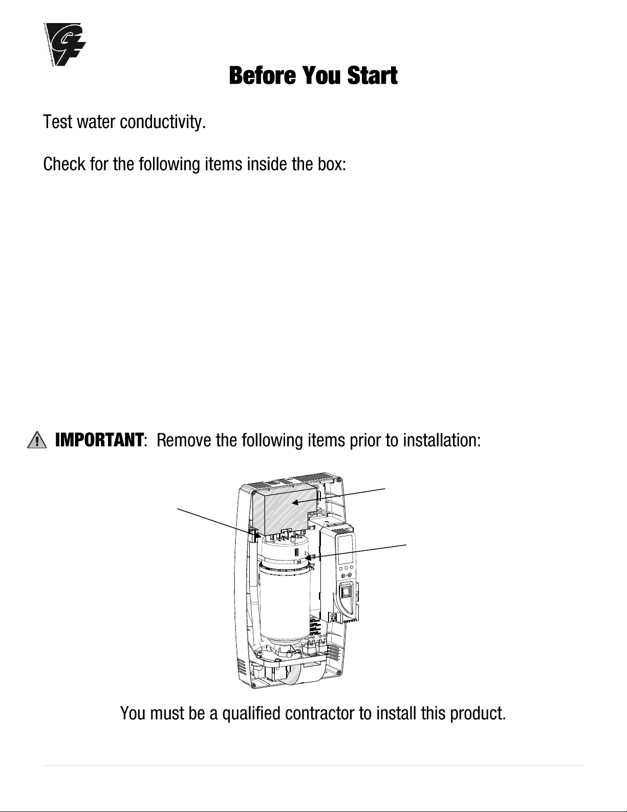
Unlatch the cylinder clamp
Remove shipping block
before installing
Remove zip tie
before installing
Page 3
General Filters
Incorporated
2 | P a g e
Before installing or handling the humidifier please carefully read and follow the instructions and safety
standards described in this manual and on the labels attached to the Elite Steam Humidifier. Test
water conductivity prior to model selection or installation.
: DISCONNECT THE MAIN POWER BEFORE OPENING OR SERVICING THE HUMIDIFIER!
: ELECTRIC SHOCK HAZARD! The humidifier has components that are under power!
: SCALDING HAZARD! The humidifier has hot parts (212°F / 100°C).
: Your humidifier requires water to operate. DO NOT mount it above materials or machinery that
could be damaged if a leak occurs. General Filters, Inc. assumes no responsibility for consequential or
inconsequential damage as a result of any leaks.
: DO NOT introduce steam into duct that has interior insulation.
:
• Install the humidifier out of the reach of children.
• The humidifier must be installed in accordance with all local and national standards.
• All service and/or maintenance operations must be performed by qualified personnel who are aware of the
necessary precautions and are capable of performing the operations correctly.
• The conditions of the environment and the power supply voltage must comply with the specified values listed
on the data label in the humidifier.
• All other uses and modifications made to the humidifier that are not authorized by the manufacturer are
considered incorrect, and the manufacturer assumes no liability for the consequences of any such unauthorized
use.
: Before Beginning Installation:
• Check for shipping damage to cartons. Mark the shipping waybill accordingly.
• Open cartons and check for any hidden damage. Mark the shipping waybill accordingly.
• Check packing slip to ensure all items have been received. Notify General Filters, Inc. of any shortages or
damaged parts.
You must notify General Filters, Inc. within 5 working days of any shortages.
: Disposal of the parts of the humidifier:
• The humidifier is made up of metallic and plastic parts.
• All parts must be disposed of according to the local standards on waste disposal.
Page 4

General Filters
Incorporated
3 | P a g e
TABLE OF CONTENTS
1. How The Elite Steam Humidifier Works 4
1.1 Basic Operation 4
1.2 Cylinder Life 5
1.3 Calculating Humidity Load 5
2. Models 6
3. Installation 7
3.1 Positioning 7
3.2 Mounting / Unit Dimensions 7
3.2 Fastening to The Wall 8
3.3 Plumbing 9
3.4 Steam Distribution 10
3.4 Installing the Steam Manifold 11
3.2 Correct Manifold Installation Digram 12
3.5 Power Wiring 13
3.6 Control Wiring 13
3.2 Control Wiring, Cont. 14
3.7 Wiring Connections 15
4. Start-Up 16
4.1 Startup Checklist 16
4.2 The Elite Steam Humidifier Controller 16
4.3 Starting The Elite Steam Humidifier 16
4.4 Starting With A New Cylinder 16
5. Operating The Elite Steam Humidifier 17
5.1 Displaying Information 17
5.2 Selecting Signal Type 17
5.2 Changing The Maximum Production 17
5.3 Activating Manual Drain 17
5.4 Resetting The Hour Counter 18
5.5 Using The GFX3 Humidistat 18
5.6 Alarms 19
6. Trouble Shooting 20
7. Maintenance 21
7.1 Periodic Checks 21
7.2 Cylinder Maintenance 21
7.3 Replacement Parts 22
8. Technical Specifications 23
9. Limited Warranty 24
10. Remote Mount Blower Instructions 26
Page 5
General Filters
Incorporated
4 | P a g e
1. HOW THE ELITE STEAM HUMIDIFIER WORKS
1.1 Basic Operation
The Elite Steam Humidifier is an electrode humidifier. Unlike heating
elements, electrode steam humidifiers produce steam for humidification
by passing electric current through the water between metal electrodes
inside the plastic steam generator cylinder. Steam output is directly
proportional to the conductivity of the water and the amount of electrode
immersed in the water. Test the water prior to installation with a
conductivity tester (use GFI #5539 or CGF #GF-AP-2 or similar).
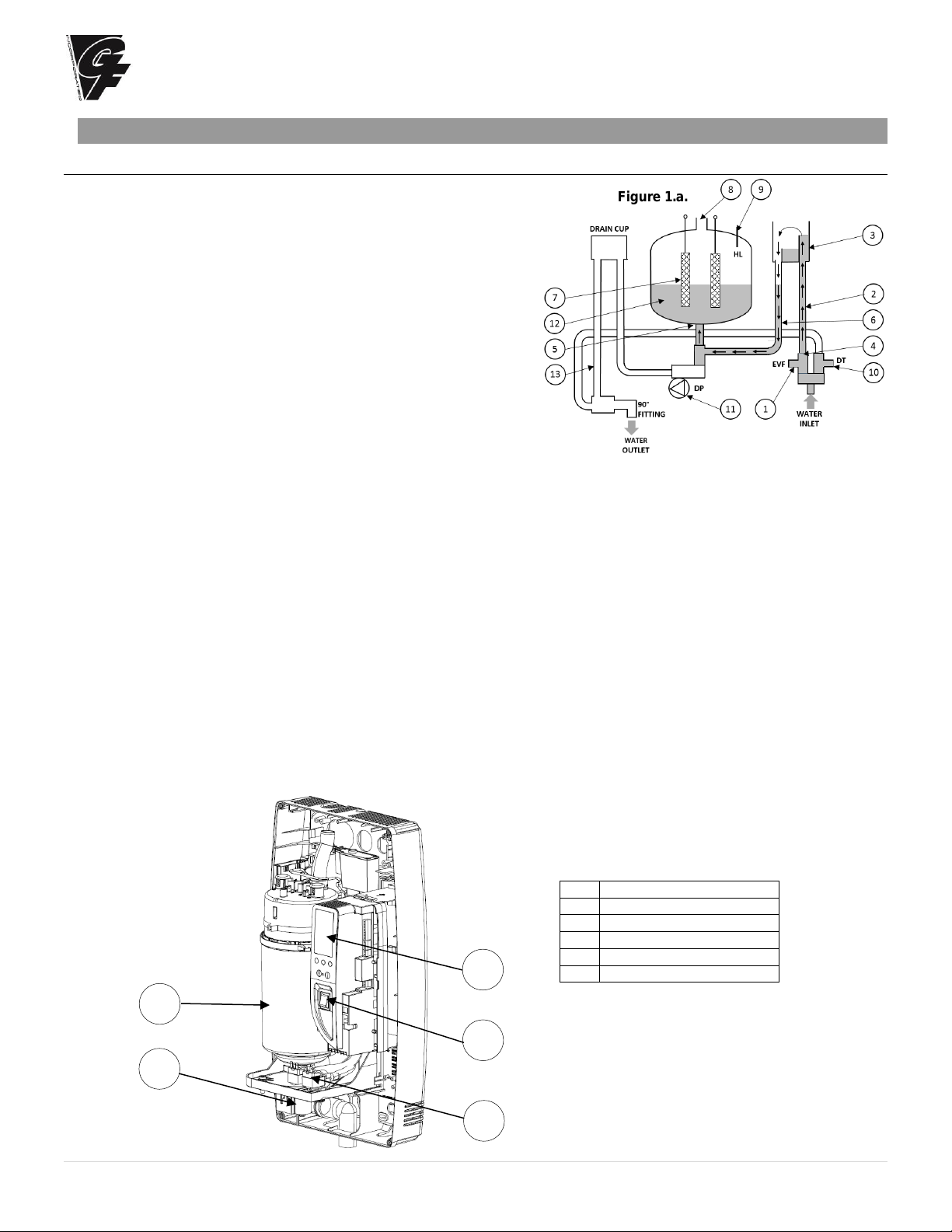
On a call for humidity, the Elite Steam controller will open the water fill
valve (1) and allow water to enter the cylinder. A flow restrictor (4)
prevents the unit from filling too quickly or with too much pressure. The
water flows up the fill tube (2) and into the fill cup (3). Water then flows
over the dam in the fill cup (3), which creates a 1” air gap to prevent
backflow of contaminated water into the feed lines, through the fill tube
(6) and into the bottom of the steam cylinder (5). Any backflow or
overflow of water travels through the overflow hose (13) to the drain.
As the water fills the cylinder, it will reach the electrodes (7) and electrical current will begin to flow. As the water continues to
fill the cylinder, the current will increase. This is monitored by an amperage transformer connected to one of the power wires
located on the electronic controller. When the desired current is reached, the fill valve will close (1) and the water will then
begin to warm and produce steam. If the water reaches the cylinder full probe (9) or if current rises too much, the drain pump
(11) will be activated to drain away some water and reduce the current flow to acceptable levels. Note that any time the drain
pump is activated, the tempering valve (10) will be opened for tempering the hot drained water down to 140°F / 60°C in
accordance to local and national standards (See Figure 1.a.).
Periodically, based on the incoming water conductivity, the unit will activate the drain pump (11) and drain water to reduce
mineral concentration. Every 120 hours the unit automatically drains to remove mineral sediment on the bottom of the cylinder.
A strainer (12) in the cylinder helps to prevent mineral debris from jamming the drain pump (11).
If the Elite Steam Humidifier remains powered but idle (i.e. without producing steam) for more than 72 hours (3 days), the
cylinder will automatically be emptied of water and will not refill until the unit is restarted. If there is no water in the cylinder,
there will be no current flow and no steam production.
The electrodes do not burn out, but they will eventually become completely coated with mineral and the cylinder will then need
to be replaced. Cleaning cylinders may cause electrode damage, therefore voiding its warranty. See 7.2.2 maintenance section
on page 21.
No.
Description
A
Steam Generator Cylinder
B
User Interface/Display
C
ON/OFF Switch
D
Fill & Tempering Valves
E
Drain Pump
Table 1.a
F
Figure 1.a.
Figure 1.b
E
D
C B A
Page 6

General Filters
Incorporated
5 | P a g e
1.2 Cylinder Life
1.2.1 Basics of the Steam Cylinder
The Steam Cylinder is the engine of the humidifier. As the water is evaporated inside the cylinder, minerals are left behind.
Much of these minerals are removed through the cylinder drain, however, some are deposited on the walls of the cylinder and
the cylinder electrodes. When a lower section of the electrodes develops a thick coating, the water level is raised to expose
clean electrode surface. Eventually minerals cover the electrodes’ entire length with a thick coating and little electrical current
can pass between them, resulting in poor steam output. The humidifier can sense the low amperage and will display the E6
Cylinder Exhausted error code. There are several factors that influence cylinder life:
1.2.2 Water
Water characteristics (mineral percentage and types) influence cylinder life and can vary greatly from place to place. Most
water conditions result in flaky scale that eventually fills the bottom of the cylinder until it can no longer function. Water with
high silica content can result in a thin glass-like coating on the electrodes that is highly insulating resulting in shorter cylinder
life. Use only cold water. Water conductivity that is not matched to the correct cylinder will shorten cylinder life.
Water quality affects the operation of this unit, so the Elite Steam should be supplied with water that is untreated, drinkable,
not softened, and not demineralized. The water converted into steam is automatically replaced through an electric fill valve.
1.2.3 Water Filtration
Typically, additional filtration of the incoming water supply is not necessary. If, however, mineral content is known to reduce
cylinder life excessively or if cylinder life proves insufficient then water filtration can be added. In most cases the addition of a
two-element water filter can improve cylinder life. The filter should contain an activated carbon element and a particulate filter
element rated for about 5 microns or less (micron is a size measurement). The filter system should have a flow rate of at least
2 GPM. The activated carbon will absorb much of the mineral content while the particulate filter will catch any granular
material or sediment. It is important to remember that an increase in cylinder life will be accompanied by the need to replace
filter elements with each cylinder change. See https://www.generalfilters.com for a list of suitable particulate filters.
1.2.4 Humidity Load and Cylinder Life
Humidity load demands have an effect on cylinder life. Normal installations where humidity capacity is properly sized require
only intermittent periods where full humidifier capacity is required. This allows the water level in the cylinder to be increased
only as electrode segments become insulated; thus extending cylinder life.
Installations that require constant operation at full capacity will reduce cylinder life. The water level in the cylinder is, on
average, much higher and the electrodes become completely insulated more quickly.
The importance of providing adequate humidifier capacity should not be underestimated.
1.2.5 Maximum Production
Another factor affecting cylinder life is the maximum production setting. A higher production
rate will result in a shorter cylinder life (See Figure 1.c.).
1.2.6 Structures Under Construction
In high-end construction projects, humidification is often required while the structure is being finished. Humidification is
necessary to protect and stabilize wood floors, trim and decoration. Humidification load, however, in an unfinished structure
may be five to eight times higher than when finished. Elite Steam humidifiers may be operated while construction is underway,
but reduced cylinder life is to be expected and budgeted for. Good practice dictates that the steam cylinder also be replaced
once the project is complete.
1.3 Calculating Humidity Load
1.3.1 Steps to Determine Humidity Load
Humidity Load Calculation (GPD)
Total Square Footage
x Average Ceiling Height
x Factor (From Table 2.a.)
x 1.05 for each Fireplace
x 2.88 convert to gallons/day
= Gallons per Day
Table 2.a.
Pounds of Moisture / Hour / Cubic Foot *
Indoor Air
Temp °F/°C
35%
Indoor RH%
40%
45%
50%
68°F/20°C
0.00015
0.00018
0.00021
0.00024
70°F/21°C
0.00017
0.00020
0.00023
0.00026
72°F/22°C
0.00019
0.00022
0.00025
0.00028
* Based on .5 air charges per hour.
100
20%
Cylinder
Life
Figure 1.c
Page 7

General Filters
Incorporated
6 | P a g e
2. MODELS
Available Steam Models
GFI #
CGF #
Description
Parts Included
5578
DS15PBU
DS-15P w/drain pump. Standard
conductivity. Duct steam injection.
15 gallons/day (5.5 Lbs/hour) 110-120v.
Includes Humidifier and Duct Steam Injection Kit
(DMNKit) components: 6 ft. steam hose, nozzle,
GFX3 humidistat, code valve, water fill connector,
9 ft. condensate hose, water supply tubing kit, air
proving pressure switch kit.
5574
DS25PBU
DS-25P w/drain pump. Standard
conductivity. Duct steam injection,
35 gallons/day (12 Lbs/hour) 220-240v.
5577
DS25LCBU
DS-25PLC w/drain pump. Low
conductivity. Duct steam injection,
35 gallons/day (12 Lbs/hour) 220-240v.
Remote Mount Blower Kits
7665
RMB15R
RMB15 - Remote Mount Blower Kits 120v.
For DS15P only.
120V room blower assembly and grille package
7660
RMB35R
RMB35 - Remote Mount Blower Kits 230V.
For DS25 or DS25LC only.
230V room blower assembly and grille package
DMNKit
(Included With Duct Steam Humidifiers)
RMB15 / RMB35
(Sold Separately; Optional)
Page 8

General Filters
Incorporated
7 | P a g e
3. INSTALLATION
3.1 Positioning
The Elite Steam Humidifier has been designed for wall mounting and, since it is an electrode steam humidifier, should be
placed close to the point where the steam will be used to minimize the steam hose length (and the amount of condensate).
Certain minimum clearances must be maintained around the unit for safety and maintenance.
(See Table 3.a. and Figure 3.a.)
DO NOT introduce steam into duct that has interior insulation.
3.2 Mounting / Unit Dimensions
3.2.1 Removing the Front Cover
The front cover is secured by four screws located at the four corners of the unit. Use a Phillips head screwdriver to remove
the four cover screws. Then simply pull the front cover away from the back part of the unit. Return it in reverse order.
Be careful not to over-tighten the screws.
(See Figure 3.b. and Table 3.b.)
Inch
Millimeters
A
6”
(150 mm)
B
6”
(150 mm)
C
6”
(150 mm)
D
6”
(150 mm)
E
24”
(600 mm)
max. 0.2°
Figure 3.a.
Inch
Millimeters
A
13.5“
341 mm
B
8.1“
204 mm
C
23.7“
600 mm
Pounds
Kilograms
Weight empty
18 lbs
8kg
Weight packaged
22 lbs
10kg
Weight installed with water
26 lbs
12kg
Unit Dimensions
Table 3.a.
Figure 3.b.
Table 3.b.
Page 9

General Filters
Incorporated
8 | P a g e
3.2.2 Fastening to the Wall
Using the supplied template, drill mounting holes (as indicated by “A” in Figure 3.c.) in the wall. Secure the Elite Steam
Humidifier firmly to the wall using the supplied screws and anchors.
TOP
BOTTOM
Figure 3.c.
A A A
A
Page 10

General Filters
Incorporated
9 | P a g e
3.3 Plumbing
3.3.1 Water Characteristic Requirements
The humidifier must be supplied with water with the following characteristics:
• Pressure between 20psi and 110psi or 0.1 and 0.8 MPa (1 and 8 bar)
• Temperature between 33°F and 104°F or 1°C and 40°C
• Flow-rate minimum of 0.45 L/min or 0.21gpm
• Hardness no greater than 40°fH (equal to 400 ppm³ of CaCO)
• Conductivity from 125 to 1250 μS/cm
• Absence of organic compounds
• The characteristics of the water of supply must fall within the following limits (Tables 3.c and 3.d):
Table 3.c. Table 3.d.
LIMIT VALUES FOR LOW SALT CONTENT WATER LIMIT VALUES FOR NORMAL WATER
Units
Min
Max
Units
Min
Max
Hydrogen ions (pH)
7 8.5 Hydrogen ions (pH)
7 8.5
Specific conductivity (R,20°C)
μS/cm
300
Specific conductivity (R,20°C)
μS/cm
125
500
Total dissolved solids (c R)
mg/l
(*)
(*) Total dissolved solids (c R)
mg/l
(*)
(*)
Dry residue at 180°C
mg/l
(*)
(*) Dry residue at 180°C
mg/l
(*)
(*)
Total hardness
mg/l CaC³O
150
400 Total hardness
mg/l CaC³O
0
200
Temporary hardness
mg/l CaC³O
=
200 Temporary hardness
mg/l CaC³O
=
150
Iron + Manganese
mg/l Fe + Mn
=
0.2 Iron + Manganese
mg/l Fe + Mn
=
0.2
Chlorides
ppm Cl
=
30 Chlorides
ppm Cl
=
20
Chlorides
mg/Si2O
=
20 Chlorides
mg/Si2O
=
20
Chlorine residue
mg/l Cl-
=
0.2 Chlorine residue
mg/l Cl-
=
0.2
Calcium sulphate
mg/l CaS4O
=
100 Calcium sulphate
mg/l CaS4O
=
60
(*) Values dependent on the specific conductivity: in general: cR~=0.65*σR, 20°C; R180~=0.9*σR, 20°C
Note: There is no relationship between the hardness and conductivity of water.
Water conductivity must be matched by specifications of the steam cylinder. Check or know the water conductivity of
the proposed site before installation. Replace the steam cylinder before startup if not correct. (See Table 3.e.)
Elite Steam Models
Conductivity μS/cm
Steam Cylinder
DS25LC
125-400
35-15
DS25
400-1250
35-14
DS15P
400-1250
15-14
The following water types are not acceptable:
1. Softened water (will lead to foam, electrode corrosion and greatly shortened cylinder life)
2. Water containing disinfectants or corrosion inhibiters (potential irritants)
3. Industrial water, boiler water or water from cooling circuits
4. Any potentially chemically or bacteriologically-contaminated water
5. Heated water
3.3.2 Water Supply Connection
The fill valve and the water supply line should be connected by a soft ¼” poly hose
capable of absorbing water hammering in order to avoid damage to the fill valve. The
water line may be routed through the back or through the bottom of the unit. With poly
tubing, a tubing support must be used to prevent tubing collapse and leaks. The fitting
threads onto the fill valve inlet located on the bottom of the humidifier using a 3/4” G
connection (supplied). Note: As there is a strainer built into the fill valve fitting
underneath the unit that requires periodic cleaning, be sure to allow clearance
for access (See Figure 3.d.).
Fill valve and filter
Water drain
Figure 3.d
Table 3.e.
Page 11

General Filters
Incorporated
10 | P a g e
3.3.3 Water Drain
The Elite Steam Humidifier requires a connection to a drain. The drain pipe may be routed out the bottom of the unit using
the included grey 90° angle fitting. The drain pipe can be MIN 1-1/2” ID PVC, CPVC or polypropylene. The drain pipe is not
glued or otherwise attached to the (supplied) 90° drain elbow, so it must be supported by itself. A coupling (field supplied)
should be used. The Elite Steam Humidifier includes a drain tempering valve that runs whenever the drain pump runs and
flushes cool water into the drain line to insure the drain water temperature never exceeds 140°F or 60°C. The drain water
characteristics are:
• Drain Flow Rate – See Technical Specifications (Section 8)
• Drain Pipe – 1 ½” ID
• Temperature 140°F or 60°C
3.3.4 Drain Pipe
When using a bottom outlet drain, attach the included 90° fitting to the drain outlet. The drain outlet may be rotated.
: DO NOT connect supplied 90° grey drain elbow directly to drain pipe. The drain pipe must flow freely
and without back pressure.
3.3.5 Condensate Pump
When using a Condensate Pump, ensure pump selected is capable of handling 7.0 GPM for up to 10-15 seconds. See
https://www.generalfilters.com for a list of suitable condensate pumps.
3.4 Steam Distribution
3.4.1 Steam Nozzle Injection (included) (Used when air flow is greater than 1000 CFM)
The maximum allowed duct static pressure is 2 in WC.
The Elite Steam Humidifier duct injection models include a plastic duct injection manifold (See Figure 3.i. and
Table 3.f. for associated measurements).
Airflow 1000 cfm min.
Airflow
Min 8”
Height >8”
=
=
Airflow
1000 cfm min.
1/3 Height
Airflow
1000 cfm min.
=
=
24” mi n
Upstream
36”mi n
Downstream
Inches
Millimeters
A
1.24”
31.5 mm
B
1.96”
50 mm
C
2.20”
56 mm
D
2.26”
57.5 mm
E
3.93”
100 mm
F
0.31”
8 mm
G
0.86”
22 mm
H
1.18”
30 mm
I
0.47 or 0.87”
12 or 22 mm
Figure 3.j
DO NOT introduce steam into a duct that has interior insulation.
Table 3.f.
Figure 3.i
Bottom Installation
Horizontal Duct
Side Installation
Horizontal Duct
Side Installation
Vertical Duct
Steam Nozzle
Page 12

General Filters
Incorporated
11 | P a g e
3.4.2 Steam Manifold Injection (Additional Kit Required) (Used when air flow is between 600 and 1000 CFM.)
If a duct steam manifold is to be used, select an accessible location on the duct, allowing at least 36” of straight duct (no elbows or
obstructions) after the point where the nozzle/manifold will be installed and the clearances can be maintained as per the following
drawings. To mount the steam manifold, cut or drill a 2-1/2” hole in the duct (See Figure 3.j.). Apply caulk to the mounting plate of
the manifold. Attach the manifold to the duct using (4) #10 sheet metal screws (supplied). The manifold must be level, or vertical
with condensate outlet oriented to the bottom.
: Allow 5 feet (1-1/2 M) of straight return duct downstream of the distributor pipe or nozzle for absorption of the steam.
Always allow 3 feet (0.9M) of straight supply duct upstream of the distributor pipe or nozzle for evaporation of the steam. Turbulent
air flow may require longer lengths.
Optional stainless-steel steam manifold
(Canada: GF-DPO30 Kit 12” or GF-DPO45 Kit 17 ½” / USA: DPO30D22R 12” or DP045D22RO 17.5”).
Installing the Steam Nozzle (Section 3. 4.1) or Manifold (Section 3.4.2)
1. Cut a round hole in the side of the duct to match either the nozzle or manifold diameter.
2. Apply silicone sealant to the mounting plate and insert the nozzle or manifold through the hole and secure with sheet metal
screws (See Figure 3.k.).
3. Connect the steam and condensate hoses using the hose clamps supplied. (Note: end support bracket supplied only
with 36” and longer distributors.)
3.4.3 Return Condensate Connection
The return condensate hose from the nozzle must be trapped. Coil the hose into a vertical loop and secure it below the nozzle. This
trap prevents steam from being released into the cabinet. The hose end may be run through the knockout at the top of the humidifier
and inserted into the hole located on top of the fill cup. The hole may be enlarged to suit (See Figure 3.l. below).
3.4.4 Steam Hoses
: MOST OPERATIONAL PROBLEMS ARE CREATED BY IMPROPER STEAM PIPING FROM THE
HUMIDIFIER UNIT TO THE DUCT DISTRIBUTOR PIPES.
To avoid these problems, remember one simple fact when running the steam hose: steam naturally flows up hill and condensate
naturally flows downhill. Run the steam hose or piping to avoid any kinks, sharp elbows, or low spots that could collect or restrict the
flow of steam to the distributor pipe, or the flow of condensate back to the humidifier. Support the hose adequately to avoid sags.
The following diagrams (See Figure 3.m. on next page) are provided as guidelines. Contact General Filters for unusual installations.
3.4.5 Steam Cylinder Hose Adapter (See Figure 3.l.)
Open sealed bag. FOLLOW INSTRUCTIONS to avoid damaging the black steam adaptor.
1. First slip narrow end of adapter into blue steam hose.
2. Insert the steam adapter with the hose installed into the steam unit through upper hole in the
shelf.
3. Insert the red O-ring into large end of black adapter.
4. Slide and lock the fixing bracket to mesh with the 2 slots in the black adapter.
5. Fix the adapter onto the cylinder, then fix the bracket using the supplied screws.
6. Firmly tighten the steam hose clamp (max tightening torque 6Nm – 53 in-lbs.)
Figure 3.j.
Figure 3.l.
25-12 Steam cylinder
hose adapter
Figure 3.k.
Condensate hose
connector
Steam Manifold
Steam Manifold
Page 13

General Filters
Incorporated
12 | P a g e
Figure 3.m.
: The standard steam unit comes with 6 feet (1.8m) of steam hose. Maximum total length of rubber steam hose is
3.65m (12 feet). The maximum total length of insulated copper tubing may be up to 6.1m (20 feet). The maximum combined allowed
length of steam hose and insulated copper tubing is 9.75m (32 feet). In all cases, minimize sharp bends and elbows. Use two 45°
elbows instead of one 90° elbows. Hose inner diameter 7/8” (22 mm); Hose outer diameter 1 ¼” (30 mm). Additional steam hose is
available GFI #7513 / CGF #GF-20-2.
3.4.6. Remote Mount Blower
Refer to Section 10 for detailed Remote Mount Blower Installation Instructions.
20%
5%
20% 20%
5%
1,5 m (5 FT max.)
3 m (10 FT max.)
20%
0,9 m (3
FT max.)
1,5 m (5 FT max.)
1,5 m (5 FT max.)
YES
NO
P - TRAP
NOTE:HEIGHT OF TRAPSMUSTBE GREATER
THAN THE DUCTSTATICPRESSURE
NOTES:
• SLOPEPIPING UPIN DIRECTION OFSTEAMFLOWAT20% OR GREATER, WHICH MEANS 65,5mm x 305mm ( 2 1/ 2” PER FOOT);
• SLOPEPIPING DOWN IN THE DIRECTION OFSTEAM FLOWAT 5% OR GREATER, WHICH MEANS 20mm x305mm (3/4” PER FOOT);
• MAX. LENGTH OFRUBBER STEAM HOSE IS 3 m (10FT).
• HEIGHT OF P-TRAPSMUST BE GREATER THAN THE DUCT STATICPRESSURE.
TYPICAL INSTALLATION
WHEN UNIT IS ABOVE
THE DISTRIBUTORPIPE
GENTLE BEND
OBSTRUCTION
SUPPORTED STEAM HOSE
AND/ORCOPPER PIPE
DRAINS
IF NO TRAP
WITH TRAP
DRAINS
IF NO SLOPE
NO SLOPE
NO SLOPE
KINKED
NO TRAP
UNDRAINED
ELBOW
UNDRAINED
ELBOW
NO DISTRIBUTION
PIPE DRAIN
SAG
NOTES:
• Slope piping up in direction of steam flow at 20% or greater, which means 1-1/2” per foot (65.5mm x 305mm).
• Slope piping down in the direction of steam flow at 5% or greater, which means ¾” per foot (20mm x 305mm).
• Max Length of rubber steam hose is 10 feet (3m).
• Height of p-traps must be greater than the duct static pressure.
Page 14

General Filters
Incorporated
13 | P a g e
3.5 Power Wiring
Check that the power supply voltage to be connected matches the value indicated on
the rating plate inside the electrical panel.
Insert the power and ground connection cables into the electrical panel compartment
using the strain reliefs supplied and connect to the terminals. An external fused
disconnect must be installed. (See Figure 3.p.)
All wiring must be in accordance with local, state and national electric codes.
NOTE: to avoid unwanted interference, the power cables should be kept separate
from any control wiring.
NOTE: Tolerance allowed on main voltage = - 15% to + 10%.
Connect power wires to the power terminal block located at the bottom left of the
control module, polarity does not matter. (See Figure 3.p.)
Connect the ground wire to the unit’s chassis ground, located just behind the power
wiring terminal block. (See Figure 3.q.)
Model
Power supply
(single phase)
Steam Output
(lbs/hr)
Steam
Output
(kg/h)
POWER
(kW)
CURRENT
(A)
EXTERNAL
POWER WIRES
EXTERNAL FUSE (A)
OR BREAKER
DS15
110Vac 50/60Hz
5.5
2.5
1.80
16.40
AWG10
25
DS25/DS25LC
230Vac 50/60Hz
12
5.4
3.89
16.95
AWG10
25
(Since 25A breakers are not readily available in the Canadian market, use a 30A DP breaker.)
3.6 Control Wiring
Elite Steam Humidifiers allow for the connection of any simple or automatic
humidistat, safety devices such as high-limit humidistat, air flow proving switch, or
remote ON/OFF switch (Figure 3.r.).
The humidifier is operated by the closing of a mechanical humidistat H, or by the
closing of a voltage-free remote contact, or alternatively by a combination of both.
The most common is a combination of a humidistat and pressure switch. The
diagrams in the figures below show the connections to be made on the terminal block,
in case of:
Figure 3.s. Operation controlled by an external mechanical humidistat
Figure 3.t. Operation performed by a simple enabling contact
Figure 3.u. A combination of both humidistat and pressure switch (most common)
Contact AB-AB:
• Closed: humidifier enabled to produce steam (production starts
when humidistat closes).
• Open: steam production is immediately stopped.
• The remote ON/OFF contact is usually a series of external
potential-free contacts that enable the humidifier to produce
steam when all of them are closed, indicating the duct/AHU is
ready to accept steam. Connect the 12500 Pressure Switch
NO and C terminals to the AB-AB contacts.
For Example:
• Fan contact closes when fan is running.
• Downstream cooling coil contact closes when coil is off; etc.
Contact IN-GND:
• Closed: steam production starts if contact AB-AB is closed.
• Open: steam production is stopped after 5 seconds.
Figure 3.p.
Figure 3.q.
Figure 3.r.
Figure 3.u.
Figure 3.t.
Figure 3.s.
Table 3.h.
Page 15

General Filters
Incorporated
14 | P a g e
3.6.1 Connect the GFX3 Humidistat for ON/OFF Operation (Figure 3.w.)
1. Remove the humidistat from the base, squeeze the louvered base at the top and bottom.
To remove the humidistat from the wall, lift up on the humidistat and pivot top away from wall.
2. Before wall mounting, remove the black foam gasket.
3. Before return air duct mounting, remove the breakout piece.
4. If return air duct mounting, route wires between humidistat and base.
5. Mount the sensor outside the house. Do not mount on south side of the house or in direct
sunlight. Place at least 4 feet away from any exhaust vent. If in air intake, place 1 foot or
closer to outside wall. Place at least 6” higher than possible snow. Do not route sensor wire
near high voltage wires.
6. Connect the GND-IN terminals on the humidifier to the HUM terminals on the GFX3
Humidistat.
Connect the GND-24V terminals to the ACL-ACN terminals on the GFX3 Humidistat
(See Figure 3.w.).
3.6.2 Modulating Operation
Connect an external 0 to 10 VDC modulating input between terminals IN-GND. Connect any
Safety Switches (high-limit, air flow switch, remote ON/OFF) in series to terminals AB-AB. If no
safety switches are used, then a jumper must be installed between AB-AB.
DO NOT apply any voltage to AB-AB.
3.6.3 Connect the GFX50 Humidistat for Modulating Operation (Figure 3.x.)
To select signal modulating (See Figure 3.x.) Connect the power supply to the GFX50 G and G O
terminals, using the terminal GND and 24V on the Elite Steam. Note MODULATING OPERATION
requires a change in signal type. (See section 5.1.1 page 17.) Connect an external signal to the
GFX50 using the terminal IN from the Elite Steam and AOUT in GFX50. (See Figure 3.x.)
3.6.4 Safety and High Limit Switches (Field Supplied) (Figure 3.v)
Highly Recommended. Remove the jumper between terminals AB-AB and connect any simple
high-limits air flow switch (suggest part HC-201; GFI #7520 or similar); a pressure switch (suggest
part 12500; GFI #7021 or similar), and remote contacts in series to terminals AB-AB; otherwise, if
no such dry contacts are available, the jumper must remain in place between terminals AB-AB. DO
NOT apply any voltage to AB-AB. thread the control wiring through the bottom of the unit, and
the strain relief (see photo at top of previous page), and then up the side of the control module to
the top right wiring terminal blocks. Connect the control wiring to the control wiring terminal blocks
found at the top right side of the control module. (See Figure 3.v.)
3.6.5 Furnace Blower Operation / Air Conditioner Relay Interlock (Figure 3.y.)
Auxiliary DPDT safety relay: Use this method in the following situations:
1. To prevent the air conditioner from running when there is a call for humidity. The DPDT relay
will open the “Y” circuit and close the “G” circuit for operation while a call for humidity is
present (See Figure 3.y.). The demand for humidity will override the call for cooling.
2. In systems using a thermostat where G and Y are a single circuit, the DPDT relay will allow blower operation to occur without
back-feeding the compressor. DO NOT use this method when simultaneous
humidification and cooling will be desired. Use a high limit humidistat in to avoid
condensation in ductwork. The humidistat should be set to OFF during the air conditioning
season if humidification is not desired.
3. For homes without an air conditioner, see Figure 3.z.
4. For variable speed or DC systems, consult the furnace manufacturer.
Figure 3.y.
Figure 3.z.
Figure 3.w.
Figure 3.x.
Figure 3.y.
Page 16

General Filters
Incorporated
15 | P a g e
3.7 Wiring Connections
Terminals
Functions
Electrical specifications
L1-L2 -GROUND
Power supply and ground connections
Power supply 110 VAC 1-phase 50-60Hz 1.86kW or 230 VAC 1phase 50-60Hz 4.05kW
KEY
Programming port
Connecting to programming port or supervisor
AB-AB
Remote enabling input
Imposes an external NO contact; Rmax=300 Ohm; Vmax=33 Vdc;
Imax=6mAdc; humidifier enabled = contact closed
IN-GND
Humidistat control signal input
If programmed 0...10V:
Input impedance 10 kohm
If programmed ON-OFF:
Vmax 33Vdc
Imax = 5mA Rmax = 300 Ohm
NC-C-NO
NC alarm contact
Common alarm contact
NO alarm contact
250V; 8 Amp max with resistive load; 4 Amp max with inductive
load
NO-C
External fan relay (furnace blower)
250VAC; 8 Amp max with resistive load; 4 Amp max with inductive
load
24GND
Power for external humidistat
Power supply for external humidistat 24 VAC; 2 Watt
F – INT FAN
For Remote Mount Blower
For optional RMB only, not for furnace or air handler connections
3.7.1 Wiring Diagram of Controller
Always use AWG10 wires and dedicated 25A or 30A breaker for power supply connections to L1 / 2 above.
Figure 3.z.1
 Loading...