

General Electric MAC 1600 SERVICE MANUAL_SM_2028451-183_E MACTM 1600 ECG Analysis System — Product Code SDE Service Manual Software Version 1.0.4 2028451-183 Revision E

GEHealthcare
MAC™1600
ECGAnalysisSystem—ProductCodeSDE
ServiceManual
SoftwareVersion1.0.4
2028451-183RevisionE
MAC™1600ECGAnalysisSystem
English
©2008-2012GeneralElectric
Company.
AllRightsReserved.

PublicationInformation
TheinformationinthismanualappliesonlytoMAC™1600withproductcodeSDE.Duetocontinuingproductinnovation,specicationsin
thismanualaresubjecttochangewithoutnotice.
Marquette,Archivist,CardioSoft,CASE,HookupAdvisor,MAC,MARS,Mactrode,Multi-Link,MUSE,SilverTRACE,12SLandBabyMACare
trademarksownedbyGEMedicalSystemsInformationTechnologies,Inc.,aGeneralElectricCompanygoingtomarketasGEHealthcare.All
othertrademarkscontainedhereinarethepropertyoftheirrespectiveowners.
©2008–2011GeneralElectricCompany.Allrightsreserved.
Thedocumentpartnumberandrevisionappearatthebottomofeachpage.Therevisionidentiesthedocument’supdatelevel.The
revisionhistoryofthisdocumentissummarizedinthefollowingtable.
RevisionHistory,PN2028451-183
Revision
A
B
Date
10April2008Initialreleaseofdocument.
14July2009
•Expandedbatteryreplacement
procedure.
Comment
•Removedunnecessarystepsfrom
printheadreplacementprocedure.
•ModiedPartsListforversion1.0.2.
C
D
E
14November2010Revisedtoincludeservicesdisclaimer
14June2011
14February2012Revisedforv1.0.4.ChangedSDcardpart
addendum
Revisedtoincludenewsoftwarepart
number.
number
ToaccessotherGEHealthcaremanuals,gototheCommonDocumentationLibrary(CDL),locatedathttp://www.gehealthcare.com/usen/
service/biomed_tech_selfservice/services_user_doc/products/support.htmlandclickCardiology.
ToaccessOriginalEquipmentManufacturer(OEM)manuals,gotothedevicemanufacturer'sWebsite.
2MAC™16002028451-183E
14February2012

Contents
1Introduction
IntendedUser..............................................................................................7
IndicationsforUse......................................................................................7
Contraindications.......................................................................................7
PrescriptionDeviceStatement...................................................................7
RegulatoryandSafetyInformation.............................................................8
SafetyConventions...................................................................................8
SafetyHazards.........................................................................................8
PartsandAccessoriesInformation.................................................................9
ResponsibilityoftheManufacturer.................................................................9
ResponsibilityofthePurchaser/Customer........................................................9
Symbols................................................................................................10
Training.....................................................................................................13
EquipmentIdentication...........................................................................13
ProductLabel.........................................................................................13
SerialNumberFormat...............................................................................14
ProductCodes........................................................................................14
ServiceInformation...................................................................................15
ServiceRequirements...............................................................................15
AdditionalAssistance................................................................................15
ManualInformation..................................................................................15
IntendedAudience...................................................................................15
ManualPurpose......................................................................................15
DocumentConventions.............................................................................15
RelatedDocuments...................................................................................17
2EquipmentOverview
FrontView.................................................................................................19
SideView...................................................................................................20
RearView..................................................................................................21
Keyboard...................................................................................................22
Keyboard(StressOption)...........................................................................24
2028451-183EMAC™1600
3

BlockDiagram...........................................................................................26
Hardware/FirmwareArchitecture.............................................................27
3Troubleshooting
GeneralFaultIsolation..............................................................................29
PowerUpSelf-Test...................................................................................29
PoorQualityECGs....................................................................................30
VisualInspection......................................................................................30
EventLogging...........................................................................................31
SettingUpEventLogging...........................................................................31
ExportingtheEventLog.............................................................................33
PerformingDiagnosticTests.....................................................................33
AccessingtheSystemDiagnosticsFunction....................................................33
TestingtheDisplay...................................................................................35
TestingtheSpeaker..................................................................................36
TestingtheKeyboard................................................................................37
TestingtheAcquisitionModule....................................................................38
CheckingBatteryStatus.............................................................................38
TestingtheWriter....................................................................................39
TestingtheRS232Port..............................................................................42
TestingtheLANOption..............................................................................43
TestingtheModem...................................................................................44
TestingtheUSBPort.................................................................................45
TestingthePatientLeadWires.....................................................................46
4Maintenance
EquipmentProblems:ECGDataNoise......................................................46
ErrorCodes...............................................................................................47
AcquisitionErrorCodes..............................................................................47
PrinterErrorCodes...................................................................................49
FrequentlyAskedQuestions.....................................................................50
Maintenance..........................................................................................50
SystemSetup..........................................................................................53
Clinical..................................................................................................55
NavigatingtheUserInterface......................................................................55
RecommendedMaintenance....................................................................59
RequiredToolsandSupplies.....................................................................59
FRUReplacementProcedures...................................................................60
HighLevelFRUIdentication.......................................................................60
PreparingSystemforFRUReplacement.........................................................61
ReplacingthePatientCable........................................................................61
ReplacingBarcodeReaderorBarcodeReaderCable.........................................62
ReplacingthePaperTrayAssembly...............................................................64
ReplacingtheBattery................................................................................64
ReplacingtheKeyboard.............................................................................67
ReplacingtheDisplayAssembly...................................................................71
ReplacingtheInternalModem(Option)..........................................................71
ReplacingthePowerSupplyAssembly...........................................................72
ReplacingtheAcquisitionBoardAssembly......................................................75
ReplacingtheKISSPumpAssembly(Option)....................................................77
4
MAC™16002028451-183E

5PartsLists
ReplacingthePrinterAssembly....................................................................80
ReplacingthePrinterBoard........................................................................86
ReplacingthePrinthead.............................................................................88
ReplacingtheOpticalSensors.....................................................................92
ReplacingtheMainboard/ETEModuleAssembly...............................................94
FunctionalCheckout.................................................................................99
VisualInspection....................................................................................100
FunctionalCheckoutProcedures................................................................101
ElectricalSafetyChecks..........................................................................102
UpdatingSoftware.................................................................................104
ConditioningTheBatteryPack...................................................................106
OrderingParts.........................................................................................109
GeneralInformation...............................................................................109
FieldReplaceableUnits(FRUs)................................................................110
MAC1600UpperLevelAssembly,PN2032093...............................................110
PowerSupplyFRUKit,PN2035703-001.......................................................117
MainboardETEAssemblyFRUKit,PN2035704-001.........................................117
AcquisitionAssemblyFRUKit,PN2035705-001..............................................117
CableHarnessFRUKit,PN2035707-001......................................................117
DisplayCoverAssemblyFRUKit,PN2035706-001..........................................118
PrinterAssemblyFRUKit,PN2035702-001...................................................118
PaperTrayAndPrinterDoorFRUKit,PN2035711-001.....................................118
DisplayAssemblyFRUKit,PN2035700-001..................................................118
PrinterBoardAssemblyFRUKit,PN2036813-001...........................................119
KISSPumpAssemblyFRUKit,PN2036814-001..............................................119
KISSPumpHardwareFRUKit,PN2036815-001..............................................119
InternalModemFRUKit,PN2036816-001....................................................119
PrintheadFRUKit,PN2036817-001............................................................120
OpticalSensorAndBracketFRUKit,PN2036818-001......................................120
FastenerHardwareFRUKit,PN2035708-001................................................121
MiddleAndBasePlasticFRUKit,PN2036812-001...........................................122
PlasticsKit,PN2035709-001.....................................................................122
Keyboards,Non-Stress............................................................................123
Keyboards,Stress..................................................................................124
DataMatrixBarcodeScannerKits..............................................................125
PowerCords.........................................................................................126
ATechnicalSpecications
BElectromagneticCompatibility
ElectromagneticCompatibility(EMC)......................................................133
GuidanceAndManufacturer’sDeclaration-ElectromagneticEmissions...............133
GuidanceAndManufacturer’sDeclaration-ElectromagneticImmunity................134
GuidanceAndManufacturer'sDeclaration-ElectromagneticImmunity................136
RecommendedSeparationDistances..........................................................137
EMCExceptionsDisclosure.......................................................................139
CEMC-CompliantSupplies&Accessories
Introduction............................................................................................141
StandardAccessories..............................................................................141
2028451-183EMAC™1600
5

ValueAccessories...................................................................................142
ThermalPapers.......................................................................................142
Country-SpecicPowerCords.................................................................143
OptionalAccessories...............................................................................143
6MAC™16002028451-183E

Introduction
Thischapterprovidesgeneralinformationrequiredfortheproperuseoftheproduct
andthemanual.Familiarizeyourselfwiththisinformationbeforeusingtheproduct.
IntendedUser
Theintendeduserofthistechnicalinformationisservicerepresentativesandtechnical
personnelsotheycanmaintaintheequipmenttotheassemblylevel.
IndicationsforUse
TheintendeduseofthisdeviceistorecordECGsignalsfromsurfaceECGelectrodes.
Thisdevicecananalyze,record,andstoreelectrocardiographicinformationfromadult
andpediatricpopulations.Thisdatacanthenbecomputeranalyzedwithvarious
algorithmssuchasinterpretiveECGandsignalaveragingforpresentationtotheuser.
1
Thisdeviceisintendedforuseunderthedirectsupervisionofalicensedhealthcare
practitioner.
Contraindications
TheMAC1600deviceisNOTintended:
•tobeusedduringpatienttransport,
•tobeusedforintra-cardiacapplications,
•tobeusedasavitalsignsphysiologicalmonitor,or
•toprovidealarmsforArrhythmiadetection.
TheArrhythmiadetectionmodeisprovidedfortheconvenienceofautomatic
documentation.
PrescriptionDeviceStatement
CAUTION:
UnitedStatesfederallawrestrictsthisdevicetosalebyorontheorderofa
physician.
2028451-183EMAC™1600
7
Introduction
RegulatoryandSafetyInformation
Thissectionprovidesinformationaboutthesafeuseandregulatorycomplianceof
thisdevice.Familiarizeyourselfwiththisinformationandreadandunderstandall
instructionsbeforeattemptingtousethisdevice.Thesystemsoftwareisconsidered
medicalsoftware.Assuch,itwasdesignedandmanufacturedtotheappropriate
medicalregulationsandcontrols.AnyexceptionsarenotedintheCompliance
Information-Exceptionssection.
NOTE:
Disregardingthesafetyinformationprovidedisconsideredabnormaluseof
thisdeviceandcouldresultininjury,lossofdata,andvoidanyexistingproduct
warranties.
SafetyConventions
AHazardisasourceofpotentialinjurytoaperson,property,ortheproduct.
ThismanualusesthetermsDANGER,WARNING,andCAUTIONtopointouthazards
andtodesignateadegreeorlevelofseriousness.Familiarizeyourselfwiththe
followingdenitionsandtheirsignicance.
DenitionsofSafetyConventions
SafetyHazards
Thefollowingmessagesapplytotheproductasawhole.Specicmessagesmay
alsoappearelsewhereinthemanual.
DANGER:
WARNING:
WARNING:
Safety
Convention
DANGER
WARNING
CAUTION
Donotuseinthepresenceofammableanesthetics.
CONNECTIONTOMAINS.ThisisclassIequipment.
Themainsplugmustbeconnectedtoanappropriatelygroundedpowersupply.
BATTERYOPERATION.Iftheintegrityoftheprotectiveearthconductorisindoubt,
operatetheunitfromitsbattery.
Denition
Indicatesanimminenthazard,which,ifnotavoided,willresultindeath
orseriousinjury.
Indicatesapotentialhazardorunsafepractice,which,ifnotavoided,
couldresultindeathorseriousinjury.
Indicatesapotentialhazardorunsafepractice,which,ifnotavoided,
couldresultinminorpersonalinjuryorproduct/propertydamage.
8MAC™16002028451-183E

CAUTION:
PartsandAccessoriesInformation
WARNING:
Introduction
Thisequipmentcontainsnouserserviceableparts.Referservicingtoqualied
servicepersonnel.
U.S.Federallawrestrictsthisdevicetothesalebyorontheorderofaphysician.
PATIENTSAFETY—Toensurepatientsafety,useonlypartsandaccessories
manufacturedorrecommendedbyGEHealthcare.
ContactGEHealthcareforinformationbeforeconnectinganydevicestothis
equipmentthatarenotrecommendedinthismanual.
IftheinstallationofthisequipmentintheU.S.A.uses240Vratherthan120V,the
sourcemustbeacenter-tapped,240V,single-phasecircuit.
Partsandaccessoriesmustmeettherequirementsoftheapplicable60601safety
standards,and/orthesystemcongurationmustmeettherequirementsofthe
60601-1-1MedicalElectricalSystemsstandard.
Usingaccessoryequipmentthatdoesnotcomplywiththeequivalentsafety
requirementsofthisequipmentmayleadtoareducedlevelofsafetyofthe
resultingsystem.Considerationrelatingtothechoiceshallinclude:
•UseoftheaccessoryinthePatientVicinity.
Patientvicinityisdenedasaspace,withinalocationintendedforthe
examinationandtreatmentofpatients,extending6ft.(1.83m)beyondthe
normallocationofthebed,chair,table,treadmill,orotherdevice(s)supporting
thepatientduringexaminationandtreatment,andextendingverticallyto8ft.
2.4in.(2.5m)abovetheoor.
•Evidencethatthesafetycerticationoftheaccessorywasperformedin
accordancewiththeappropriate60601-1and/or60601-1-1standard(s).
ResponsibilityoftheManufacturer
GEHealthcareisresponsiblefortheeffectsofsafety,reliability,andperformanceon
GE-suppliedhardwareonlyifthefollowingconditionsaremet:
•Assemblyoperations,extensions,readjustments,modications,orrepairsare
carriedoutbypersonsauthorizedbyGEHealthcare.
•Theelectricalinstallationoftherelevantroomcomplieswiththerequirementsof
theappropriatelocal,state,andothergovernmentregulations.
•Theequipmentisusedinaccordancewiththeinstructionsforuse.
ResponsibilityofthePurchaser/Customer
Thecustomerisresponsibleforprovidingappropriatedesks,chairs,electricalwall
outlets,networkconnections,analogphonelines,andforlocatinganyofthesystem
componentsdescribedinthismanualincompliancewithalllocal,state,andnational
codes.
2028451-183EMAC™16009

Introduction
Symbols
Thefollowingsymbolsmayappearonthedeviceoritspackaging.Familiaritywith
thesesymbolsassistsinthesafeuseanddisposaloftheequipment.Forequipment
symbolsnotshown,refertotheoriginalequipmentmanufacturers(OEM)manuals.
Debrillation-prooftypeBFequipment.
Equipotentialgroundpoint
Protectiveearthterminal
Attention,seeinstructionsforuse
Consultinstructionsforuse.
Catalogue(part)number.
Serialnumber.
Forusebyorontheorderofaphysicianor
personslicensedbystatelaw.(USOnly)
Dateofmanufacture.
Manufactureraddress.
Environment-friendlyUsePeriodperChinese
standardSJ/T11363-2006(Chinaspecic).
10MAC™16002028451-183E

Thiswayup.
Recyclable.
Atmosphericlimits.
Temperaturelimits.
Humiditylimits.
Introduction
Keepdry.
Fragile.
Donotthrowordisposeofinre.
2028451-183EMAC™160011

Introduction
Indicatesthedeviceisclassiedastype20
forsolidandliquidingressperIEC/EN60529.
•X=Ingressofsolidobjects:
•0non-protected
•1>=50mmdia
•2>=12.5mmdia
•3>=2.5mmdia
•4>=1.0mmdia
•5dustprotected
•6dusttight
•Y=ingressofliquid
•0nonprotected
•1verticaldripping
•2dripping(15degtilted)
•3spraying
•4splashing
•5jetting
•6powerfuljetting
•7temporaryimmersion
•8continuousimmersion
SecureDigital(SD)Card.
Batchorlotnumber.
AuthorizedrepresentativeinaEuropean
country
CCCMark-ChinaCompulsoryCertication
mark
NorthAmericanProductSafetyCertication.
SymbolizescompliancewithbothCanadian
andU.S.applicablerequirements.
CEmarkingsymbolizingconformitywith
applicableEuropeanCommunitydirectives.
PCT.GOSTmarkingsymbolizingconformity
withapplicableRussianGosstandart
technicalandsafetystandards.
12MAC™16002028451-183E

Introduction
Training
Thismanualisintendedasasupplementto,notasubstitutefor,thoroughproduct
training.Ifyouhavenotreceivedtrainingontheuseofthedevice,youshouldrequest
trainingassistancefromGEHealthcare.
Toseeavailabletraining,gototheGEHealthcaretrainingwebsite
(http://www.gehealthcare.com/usen/education/index.html)andselectDiagnostic
CardiologyundertheTechnicalServiceEducationsection.
Formoreself-pacedcourseofferings,tools,andreferenceguidesyou
maynduseful,pleasevisittheGEHealthcareEducationStoreat
www.gehealthcare.com/educationstore.
EquipmentIdentication
EveryGEHealthcaredevicehasaproductlabelthatidentiestheproductname,part
number,manufacturinginformation,anduniqueserialnumber .Thisinformationis
requiredwhencontactingGEHealthcareforsupport.
ProductLabel
Theproductlabelislaidoutinthefollowingformat.Dependingontheproduct,the
labelmayvaryslightlyinformat,butitcontainsthesameinformation.
ProductLabelFormat
Item
1
2
3
4
5
6
Description
Productdescription
Productpartnumber
DateofmanufactureinYYYY-MMformat
Deviceserialnumber(Referto“SerialNumberFormat”onpage14formore
information.
Manufacturernameandaddress
Productbarcode
2028451-183EMAC™160013

Introduction
SerialNumberFormat
Eachdevicehasaserialnumberthatuniquelyidentiesthedeviceandprovides
importantinformationaboutthedevice.Theserialnumberformatisshowninthe
followingillustration:
SerialNumberFormat
ItemName
1
2
3
4
5
6
Description
ProductCodeThree-lettercodethatuniquelyidentiesthe
productline.Referto“ProductCodes”onpage
14formoreinformation.
YearManufacturedTwo-digitcodeidentifyingtheyearthedevice
wasmanufactured.Valuesrangefrom00to99
Forexample:00=2000,04=2004,05=2005
(andsoon).
FiscalWeek
Manufactured
ProductSequenceFour-digitnumberidentifyingtheorderinwhich
ManufacturingSiteOne-lettercodeidentifyingthesitewherethe
Miscellaneous
Characteristic
Two-digitcodeidentifyingtheweekthedevice
wasmanufactured.
Valuesrangefrom01to52.GEHealthcare'sscal
weekscorrespondtothecalendarweek.For
example,01=rstweekinJanuary.
thisdevicewasmanufactured.Valuesrangefrom
000to9999.
devicewasmanufactured.Forexample,F=
Milwaukee,N=Freiburg,P=Bangalore
Forexample,P=unitisaprototype,R=unitwas
refurbished,U=unitwasupgradedtomeetthe
specicationsofanotherproductcode.
ProductCodes
Theproductcodeidentiesspecicsystemplatforms.Youneedtheproductcode
beforeservicingorrequestingsupportforyourdevice.
Youcanidentifytheproductcodeusingtheserialnumberlistedontheproductlabel
locatedinoneofthefollowingplaces:
•Ontheproductlabelattachedtothebasethesystem.
•OntheproductlabelprovidedwiththeapplicationCD.
•Intheapplication:
•OnITsystems:
LaunchthesystemapplicationandclickHelp>Abouttoviewtheserialnumber.
14MAC™16002028451-183E

ServiceInformation
ServiceRequirements
Introduction
Forinformationonlaunchingtheapplication,refertotheproduct'sserviceor
operator'smanual.
•OnMACsystems:
OntheServiceOnlySetupwindow,selectSystemSetup,pressShift+F2,and
entertheservicepasswordtoviewtheserialnumber.
ContactGEHealthcaresupportifyoudonotknowtheservicepassword.
Thissectionprovidesinformationpertainingtothemaintenanceandservicingofthe
device.FamiliarizeyourselfwiththisinformationbeforerequestingservicefromGE
Healthcareoritsauthorizedrepresentatives.
Failureonthepartoftheresponsibleindividual,hospital,orinstitutionusingthis
equipmenttoimplementasatisfactorymaintenanceschedulemaycauseundue
equipmentfailureandpossiblesafetyhazards.
Regularmaintenance,irrespectiveofusage,isessentialtoensurethatthecomponents
ofthissystemarealwaysfunctionalwhenrequired.
AdditionalAssistance
GEHealthcaremaintainsatrainedstaffofapplicationandtechnicalexpertstoanswer
questionsandrespondtoissuesandproblemsthatmayariseduringtheinstallation,
maintenance,anduseofthisproduct.
ContactyourlocalGEHealthcarerepresentativetorequestadditionalassistance.
ManualInformation
Thissectionprovidesinformationforthecorrectuseofthismanual.
Keepthismanualwiththeequipmentatalltimesandperiodicallyreviewit.You
shouldrequesttrainingassistancefromGEHealthcare,ifneeded.
IntendedAudience
Thismanualisintendedforthepersonwhouses,maintains,ortroubleshootsthis
equipment.
ManualPurpose
Thismanualsuppliestechnicalinformationforservicerepresentativesandtechnical
personnelsotheycanmaintaintheequipmenttotheassemblylevel.Useitasaguide
formaintenanceandelectricalrepairsconsideredeldrepairable.Wherenecessary
themanualidentiesadditionalsourcesofrelevantinformationand/ortechnical
assistance.
DocumentConventions
Thismanualusesthefollowingconventions.
2028451-183EMAC™160015

Introduction
TypographicalConventions
ConventionDescription
BoldTextIndicateskeysonthekeyboard,texttoenter,orhardwareitemssuchas
buttonsorswitchesontheequipment.
Italicized-Bold
Text
CTRL+ESC
<space>
Enter
>
Indicatessoftwaretermsthatidentifymenuitems,buttonsoroptionsin
variouswindows.
Indicatesakeyboardoperation.Aplus(+)signbetweenthenamesoftwo
keysindicatesthatwhileholdingtherstkey,youshouldpressandrelease
thesecondkey.Forexample,PressCTRL+ESCmeanstopressandholdthe
CTRLkeyandthenpressandreleasetheESCkey.
Indicatesthatyoumustpressthespacebar.Wheninstructionsaregiven
fortypingaprecisetextstringwithoneormorespaces,thepointwhere
youmustpressthespacebarisindicatedas:<space>.Thisensuresthat
thecorrectnumberofspacesareinsertedinthecorrectpositionswithin
theliteraltextstring.Thepurposeofthe<>bracketsistodistinguishthe
commandfromtheliteraltextwithinthestring.
IndicatesthatyoumustpresstheEnterorReturnkeyonthekeyboard.Do
nottypeEnter.
Thegreaterthansymbol,orrightanglebracket,isaconcisemethodto
indicateasequenceofmenuselections.
Forexample,thestatement“Fromthemainmenu,selectSystem>Setup>
OptionstoopentheOptionActivationwindow”replacesthefollowing:
1.Fromthemainmenu,selectSystemtoopentheSystemmenu.
2.FromtheSystemmenu,selectSetuptoopentheSetupmenu.
3.FromtheSetupmenu,selectOptionstoopentheOptionActivation
window.
Illustrations
Allillustrationsinthemanualareprovidedasexamplesonly.Dependingonsystem
conguration,screensthatappearinthemanualmaydifferfromthescreensasthey
appearonyoursystem.
Allpatientnamesanddataarectitious.Anysimilaritytoactualpersonsis
coincidental.
Notes
Notesprovideapplicationtipsoradditionalinformationthat,whileuseful,arenot
essentialtothecorrectoperationoftheproduct.Theyarecalledoutfromthebody
textthroughaagwordandindentation,asfollows:
NOTE:
ThetiporadditionalinformationappearsindentedbelowtheNOTEagword.
16MAC™16002028451-183E

Introduction
RelatedDocuments
Youcanndadditionalinformationinthefollowingdocuments:
DocumentsRelatedtothismanual
PartNumberDocumentTitle
2028451-182
MAC™1600ECGAnalysisSystemOperator’sManual
2028451-183EMAC™160017

Introduction
18MAC™16002028451-183E

EquipmentOverview
TheMAC™ECGAnalysisSystemisa12–lead,12–channelsystemwitha6.5inch(165
mm)diagonaldisplay,activepatientcable,andbatteryoperation.Therearealso
optionsforcommunicationcapabilities.
FrontView
2
FrontViewoftheSystem
ItemName
1
2
2028451-183EMAC™160019
DisplayPresentswaveformandtextdata.
PowerLED
Indicatestheunitispluggedinandreceivingpower.
Description

EquipmentOverview
FrontViewoftheSystem(cont'd.)
ItemName
3BatteryLED
4
5
Indicatesvariousbatterystates:
•Solidamberlightindicatesthebatteryischarging.
•Flashingamberlightindicatesthebatteryislow.
•Nolightindicatesthebatteryisneitherchargingnor
low.
KeyboardInputdeviceforcontrollingthesystemorenteringdata.
See“Keyboard”onpage22formoreinformation.
WriterPrintsreports.
Description
SideView
SideViewoftheSystem
ItemName
1
2KISSconnector
3
20MAC™16002028451-183E
ECGsignalinputconnectorD-sub15-pinfemaleconnectorforthe
acquisitioncable.
ConnectionportfortheoptionalKISSlead
system.
CarryinghandleHandleforcarryingthedevice.
Description

EquipmentOverview
RearView
RearViewoftheSystem
ItemName
1
2COMMPortA
3
4
5
6USBconnector
7
8
Externalpowerconnector12Vpowersupplyforfutureexternaldevices.
COMMPortB
PhonejackRJ11connectorfromtheinternalmodemtoan
ACpowerconnection
LANconnection
SDcardslotSecureDigitalcardslot.Insertthecardas
Description
Donotuse.
Serialconnectorforstressdevices(bicycle
ergometerortreadmill).
Serialconnectorfordatacommunication
withaCASE/CardioSoftorMUSEsystem,or
connectiontoanexternalmodem.
analogphoneline.
StandardconnectorfortheACpowercable.
StandardUniversalSerialBusconnectorfor
USBdevices,suchastheoptionalbarcode
readerorexternalUSBkeyboard.
RJ45networkconnector .
indicatedbytheicon.Thesystemsupports
onlySDcardsformattedfortheFATorFAT16
lesystems.
2028451-183EMAC™160021

EquipmentOverview
RearViewoftheSystem(cont'd.)
ItemName
9
ExternalVideoMonitor
connection
Standard15-pinVGAconnectorforanexternal
monitor.ConnectamedicalgradeVGACRTor
medicalgradeVGAcompatibleLCDdisplay.
Description
NOTE:
Thedisplayresolutionis800by480
pixels.Duetodifferingaspectratios,the
imagemayappeardistortedonsomeLCD
monitors.Consulttheoperatingguidefor
yourLCDmonitor .
10
Equipotentialgrounding
lug
Connectnon-groundedperipheraldevicesto
ensureequipotential.
WARNING:
PATIENTINJURYTotalsystemleakagemustnotexceed300microamperes
(UnitedStates)or500microamperes(international).
Keepleakagecurrentwithinacceptablelimitswhenconnectingauxiliary
equipmenttothisdevice.
Keyboard
NOTE:
TheEnglishkeyboardisshowninthissection.
22MAC™16002028451-183E

StandardKeyboard
EquipmentOverview
ItemName
1
2
3
4
5
6
7
8
9
10
11
12
13
14
15
functionkeys(F1throughF6)Usetoselectmenuoptionsonthe
PowerswitchUsetoturnthesystemon,bringthe
LeadskeyUsetochangetheleadswhenthe
BackspacekeyUsetodeletecharacters.
ECGkey
RhythmkeyUsetoprintacontinuous,real-time
StopkeyUsetostopthewriterfromprinting.
EnterkeyUsetoadvancethefocusinawindow,
TrimpadPressthearrowstomovethecursor
ShiftkeyUsetoenteracapitalletter.Press
AltkeyUsetoselectmenuoptionsinthe
SpacebarUsetoaddaspacebetweentyped
OptionkeyUsetoenterspecialcharacterson
EsckeyUsetocloseawindowonthescreen.
StresskeysThesekeysareonyourkeyboardif
Description
screen.
systemtoStandbymode,orturnthe
systemoff.
screenisdisplayingwaveforms.
UsetoacquirearestingECG,toprint
a10–secondreportinArrhythmia
mode,ortoprinta12–leadreportin
Stressmode.
rhythmECGrhythmstrip.Pressthe
Stopkeytostoptherhythmstrip
fromprinting.(Rhythmreportsare
notstoredandyoucannottransmit
them).
ortoselectitemsfromthescreen.
left,right,up,ordown.Pressthe
centeroftheTrimpadtomovethe
focuswithinawindow,ortoselect
anitem.
shift+PtotypeacapitalP.
WindowsExplorer.
characters,ortohighlightscreen
items.
non-Englishkeyboards.
yoursystemhasthestressoption.
See“Keyboard(StressOption)”on
page24formoreinformation.
2028451-183EMAC™160023

EquipmentOverview
Keyboard(StressOption)
NOTE:
TheEnglishkeyboardisshowninthissection.
ItemName
1
2
3
4
5
6
7
8
9
10
11
12
13
Description
PretestkeyPresstoadvancetothePRETESTphase(or
advancetonextstagewithintheselected
phase).
ExercisekeyPresstoadvancetotheEXERCISEphase(or
advancetonextstagewithintheselected
phase).
RecoverykeyPresstoadvancetotheRECOVERYphase(or
advancetonextstagewithintheselected
phase).
TestendkeyPressandholdtoendthetestandstartthe
TESTENDphase.
HoldkeyPresstomaintainthecurrentstage.
(Automaticstagesequencingstops.)Press
againtoreturntostagesequencing.
SpeedW+keyPresstomanuallyincreasethetreadmillbelt
speedortheergometerload.
↑
Grade↑ ↑
StarttmillkeyPresstostartthetreadmillduringthetest.
STOPtmillkeyPresstostopthetreadmillduringthetest.
Grade↓ ↓
SpeedW-keyPresstomanuallydecreasethetreadmill
EnterBPkeyPresstoenterbloodpressurereadingsorto
CommentkeyPresstoentercommentsaboutthetest.
key
↓
key
Presstoincreasetheelevationofthe
treadmillbelt.
Presstodecreasetheelevationofthe
treadmillbelt.
beltspeedortheergometerload.
triggerareadingfromanexternaldevice.
Commentsareprintedonmanyofthenal
reports.
24MAC™16002028451-183E

EquipmentOverview
ItemName
14
15
16
Description
MedianskeyPresstoprintamediansreport.
12ldkeyPresstoprinta12–leadreport(10seconds
ofacquireddata).
RecallkeyPresstoprintaone-pagerhythmstripusing
theprevious10secondsofdata.
2028451-183EMAC™160025

EquipmentOverview
BlockDiagram
26MAC™16002028451-183E

Hardware/FirmwareArchitecture
Thehardwaresubsystemsincludethefollowing:
•CPUcore
•Display
•Keyboard
•ECGAcquisition
•Thermalprinter
•Powersupply
•Housing
EquipmentOverview
2028451-183EMAC™160027

EquipmentOverview
28MAC™16002028451-183E

Troubleshooting
GeneralFaultIsolation
Refertoyoursystem’sOperator’sManual,Chapter2,“EquipmentOverview”to
verifyoperationofthedevice.
PowerUpSelf-Test
Onpower-up,thesystemautomaticallyrunsaninternalself-test.Ifalltestspass,
youseethefollowingstart-upscreen.
3
ThenextscreentoopendependsonthePowerUpmodeselectedinSystem
Conguration.TheRestingECGmodeisthedefaultPowerUpmode.
Iftheequipmentisnotworkingproperly,considerthefollowing:
•Istheunitturnedon?
•Havetherebeenanychangesintheuse,location,orenvironmentoftheequipment
thatcouldcausethefailure?
•Hastheequipmenthardwareorsoftwarebeenmodiedsincethelastuse?
•Isoperatorerrorthecauseoftheproblem?
Trytorepeatthescenarioexactlyandcomparethattotheproperoperationofthe
equipmentdescribedinthemanual.
2028451-183EMAC™160029

Troubleshooting
•Isthebatteryinstalled?
•WhenconnectedtotheACwalloutlet,doesthegreenACpowerlightglow?
PoorQualityECGs
SeveralfactorscancausepoorECGs,including:
•Factorsintheenvironment.
•Inadequatepatientpreparation.
•Hardwarefailuresrelatedtotheacquisitionmodule.
•Leadwires,cables,orproblemsintheunit.
VisualInspection
Athoroughvisualinspectionoftheequipmentcansavetime.Smallthings,suchas
disconnectedcables,foreigndebrisoncircuitboards,missinghardware,orloose
components,canfrequentlycausesymptomsandequipmentfailuresthatmayseem
tobeunrelatedanddifculttotrack.
NOTE:
Takethetimetomakealltherecommendedvisualchecksbeforestartingany
detailedtroubleshootingprocedures.
VisualInspectionChecklist
Area
I/Oconnectorsandcables
ACpowercord
Interfacecables
Circuitboards
•Frayingorotherdamage
•Bentprongsorpins
•Crackedhousing
•Loosescrewsinplugs
•Excessivetensionorwear
•Looseconnection
•Strainreliefsoutofplace
•Moisture,dust,ordebris(topandbottom)
•Looseormissingcomponents
•Burndamageorsmellofover-heatedcomponents
•Socketedcomponentsnotrmlyseated
•PCBnotseatedproperlyinedgeconnectors
•Solderproblems:cracks,splashesonboard,incomplete
feedthrough,priormodicationsorrepairs
Lookforthefollowingproblems
Groundwires/wiring
30MAC™16002028451-183E
•Loosewiresorgroundstrapconnections
•Faultywiring
•Wirespinchedorinvulnerableposition

VisualInspectionChecklist(cont'd.)
Troubleshooting
Fasteners
Powersource
Area
Looseormissingscrewsorotherhardware,especially
fastenersusedasconnectionstogroundplanesonPCBs
•Faultywiring,especiallyACoutlet
•Circuitnotdedicatedtosystem
Lookforthefollowingproblems
NOTE:
Powersourceproblemscancausestaticdischarge,
resettingproblems,andnoise.
Keyboard
LCDdisplaylterScratches,cracks,oranopaquedisplaylter(transparent
Batterypack
SDcard
•Cutsorcracksinkeyboardmembrane
•Illegiblelabels
componentofkeyboardbezel)thatimpairviewing
•Cracked,swollen,orleakybatterypackenclosure
•Debrisonbatterypackelectricalcontacts
•CrackedSDcard
•Brokengoldcontacts
•Dirt,scratches,ordebrisoncontacts
EventLogging
SettingUpEventLogging
Eventloggingisawaytotracksystemerrors,warningsandinformationalmessages.
YoucansetupthesystemtocreateanEventLoginXMLformat.Tocongurethe
deviceforthelevelofseverityofmessageswrittentotheEventLog,usethefollowing
steps:
1.PoweronthesystembypressingthePowerbutton.
2.OntheMainMenu,pressF5(SystemConguration).
3.PressF6(More)>F6(More)>F5(ServiceSetup).
AwindowopenspromptingyoutoentertheServicepassword.
2028451-183EMAC™160031

Troubleshooting
4.TypeprodandpressF6(OK).
NOTE:
Ifthekeyboarddoesnotincludethelettersprod,type7763andpressF6
(OK).
Thefollowingwindowopens.
5.UsetheTrimpadtohighlighttheEventLogbuttonandpressEnter.
6.Enableordisableeventlogging.
•Toenableeventlogging,selecttheKeyEventLoggingcheckbox.
or
•Todisableeventlogging,deselecttheKeyEventLoggingcheckbox.
7.SelectalevelofseveritytologfromtheLogLevellist:
LogLevelWhatisloggedtotheEventLog
Error
Warning
InformationLogserrors,warningsandinformation
Logsonlyerrors.
Logserrorsandwarnings.
messages.
8.PressF6(Save)tosaveyoursettings.
32MAC™16002028451-183E
ExportingtheEventLog
1.Repeatsteps1through5in“SettingUpEventLogging”.
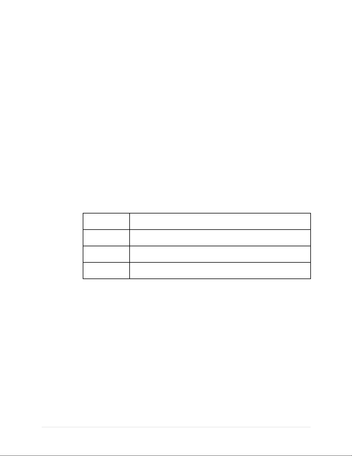
2.InsertanSDcardintheSDcardslotinthebackpanel,asshowninthefollowing
illustration:
Thegoldcontactsareface-up.
Troubleshooting
3.PressF1(ExportLogFiles).
ThecurrentEventLogle,log_0.log,iscopiedtoalogdirectory
ontheSDcard.
NOTE:
Toaccessthelogle,inserttheSDcardintoanSDcardreaderthatis
connectedtoacomputerwithaWindowsoperatingsystemandatexteditor
likeNotepadorWordPad.IfGEHealthcaretechnicalservicerequeststhe
EventLogfortroubleshootinganissue,sendtheleasanemailattachment.
PerformingDiagnosticTests
Verifythatthesystemoperatesproperlybyrunningthediagnostictests.Thesetests
checktheoperationofthedisplayscreen,speaker,keyboard,thermalwriter ,battery,
andcommunications.Thesediagnostictestsareusefultoolsfortroubleshooting
problems,andcanbeusefulasapartofsystemcheckoutprocedures.
AccessingtheSystemDiagnosticsFunction
UsetheSystemDiagnosticsmenutoperformfunctionaldiagnostictests.Usethe
followingproceduretoaccesstheSystemDiagnosticsmenu.
1.PoweronthesystembypressingthePowerbutton.
2.OntheMainMenu,pressF5(SystemConguration).
2028451-183EMAC™1600
33

Troubleshooting
3.PressF6(More)>F6(More)>F5(ServiceSetup).
AwindowopenspromptingyoutoentertheServicepassword.
4.TypeprodandpressF6(OK).
NOTE:
Ifthekeyboarddoesnotincludethelettersprod,type7763andpress
F6(OK).
TheServiceSetupmenuopens.
5.UsetheTrimpadtohighlighttheSystemDiagnosticsbuttonandpressEnter.
TheDIAGNOSTICTESTSwindowopens.
Thefollowingsectionsdescribehowtoperformthespecicdiagnostictests.Proceed
totheappropriatesectionforthetestyouneedtoperform.
34
MAC™16002028451-183E

TestingtheDisplay
Troubleshooting
UsetheDisplayTesttodetermineifthedisplaypixelsareworkingproperly.
1.OpentheDIAGNOSTICTESTSwindowasdescribedin“AccessingtheSystem
DiagnosticsFunction”onpage33.
2.SelectDisplayTest.
TheStartTestwindowopens.
3.SelectStartTest.
Thefollowingwindowopens.
4.PresstherightarrowontheTrimpadrepeatedlytomovethecolorbars
horizontallyacrossthescreen.
5.Verifythatthecolorbandpattern(red,green,blue,white)scrollsacrossthe
screen.
Passthetestifthepatternisreplicatedwithoutdiscoloration.
6.PressF1toswitchtohorizontalcolorbars.
7.PressthedownarrowontheTrimpadrepeatedly.
8.Verifythatthecolorbandpattern(red,green,blue,white)scrollsdownthe
screen.
Passthetestifthepatternisreplicatedwithoutdiscoloration.
9.PressF1tocyclethroughthesolidcolorpane(red,green,blue,white).
Foreachpane,checkforblackpixels.
2028451-183EMAC™1600
35
Troubleshooting
Passthetestifnomorethan4blackpixelsareobservedonanysinglecolor
pane.
NOTE:
Ablackpixelobservedononepanewillprobablybeobservedoneverypane.
10.PressEscorEnterwhenthetestisdone.
Thefollowingwindowopens.
11.Selectpassorfail:
•Ifthetestpassed,pressF4(Yes).
•Ifthetestfailed,pressF5(No).
Ifthedisplaytestfailed,replacethedisplayassemblyasdescribedin
“ReplacingtheDisplayAssembly”onpage71.
TestingtheSpeaker
UsetheSpeakerTesttodetermineifthespeakerisworkingproperly.
1.OpentheDiagnosticTestswindowasdescribedin“AccessingtheSystem
DiagnosticsFunction”onpage33.
2.SelectSpeakerTest.
3.Listenforabriefaudibletonecomingfromthespeaker.
Thefollowingwindowopens.
4.Selectpassorfail:
•Ifyouheardanaudibletone,pressF4(Yes).
•Ifyoudidnothearanaudibletone,pressF5(No).
Ifthespeakertestfailed,replacethemainboard/ETEmoduleassemblyas
describedin“”onpage.
36MAC™16002028451-183E

TestingtheKeyboard
UsetheKeyboardTesttodetermineifthekeyboardisworkingproperly.
1.OpentheDiagnosticTestswindowasdescribedin“AccessingtheSystem
DiagnosticsFunction”onpage33.
2.SelectKeyboardTest.
Thefollowingwindowopens.
Troubleshooting
3.Presseachkeyonthekeyboardandverifythatanasterisk(*)appearsinthe
correspondingrepresentationofthatkeyonthescreen.
Akeypassesthetestifanasteriskappearsonthescreenwhenthe
correspondingkeyispressed.
4.Totestforstickykeys,continuetopresskeysthatalreadyhaveanasteriskon
thescreenandverifythatthescreenrepresentationofthekeyishighlighted
witheachsubsequentkeypress.
Akeypassesifthekeyonthescreenhighlightswitheachrepeatedkeypress.
5.Whenthetestisdone,pressShift+F6.
Thefollowingwindowopens.
6.Selectpassorfail:
•Ifeverykeypassesthetests,pressF4(Yes).
•Ifanykeyfailsthetests,pressF5(No).
Ifthekeyboardtestfailed,replacethekeyboardassemblyasdescribedin
“ReplacingtheKeyboard”onpage67.
2028451-183EMAC™1600
37

Troubleshooting
TestingtheAcquisitionModule
UsetheAcquisitionModuleTesttodetermineiftheacquisitionboardisworking
properly.
1.OpentheDiagnosticTestswindowasdescribedin“AccessingtheSystem
DiagnosticsFunction”onpage33.
2.SelectAcquisitionModuleTest.
Awindowsimilartotheoneshowninthefollowingillustrationopens.
3.NotethetestresultandpressF6(Cancel).
4.IftheresultoftheAcquisitionModuleTestwasFailed:
a.Re-seatordouble-checkacquisitionboardharnessesandrepeatthe
b.Iftheteststillfailsafterre-seatingtheboardandcheckingtheharnesses,
c.Repeattheacquisitionmoduletestafterreplacingtheboardtoverify
d.Iftheteststillfailsafterreplacingtheacquisitionboard,replacethe
CheckingBatteryStatus
UsetheBatteryTesttodeterminethestatusoftheLithium-Ionbattery.Youmust
performthistestwhilerunningonbatterypower.
1.DisconnectthedevicefromACpowerandwaitatleastoneminute.
2.OpentheDiagnosticTestswindowasdescribedin“AccessingtheSystem
DiagnosticsFunction”onpage33.
acquisitionmoduletest.
replacetheacquisitionboardasdescribedin“ReplacingtheAcquisition
BoardAssembly”onpage75.
functionality.
mainboard/ETEmoduleasdescribedin“”onpage.
38MAC™16002028451-183E

3.SelectBatteryTest.
Awindowsimilartotheoneshowninthefollowingillustrationopens.
NOTE:
Troubleshooting
Status
BatteryLifeRemainingTheestimatedtimeremainingbasedonthe
BatteryChargeRemainingAccordingtothebatteryspecications(refer
Description
presentcurrentdraw.
Becausenoprintingisoccurringduringthis
statuscheck,thistimeiscalculatedbasedon
usingthesystemfordisplaypurposesonly.
Actualremainingbatterylifeislesswhen
usingthesystemforbothdisplayandprinting
purposes.
to“TechnicalSpecications”onpage129)you
shouldseeatleast3:00(threehours)ofBattery
LifeRemaining(displaytime)with100%Battery
ChargeRemaining.
Ifthenumbersdisplayedinthiswindowareless,
youmayrequiremorefrequentbatterycharging
oryoumaywishtoreplacethebattery.See“”
onpageforinformationonhowtoreplacethe
battery.
4.NotethebatterystatusinformationandpressF6(Cancel)toclosetheBATTERY
STATUSwindow.
TestingtheWriter
UsetheWriterTesttodetermineifthewriterisworkingproperly.
NOTE:
BeforeperformingtheWriterTest,besurethatthermalpaperisproperlyloadedin
thewritertray.
Refertoyoursystem’sOperatorManualforinstructionsonloadingpaper.
1.OpentheDiagnosticTestswindowasdescribedin“AccessingtheSystem
DiagnosticsFunction”onpage33.
2.SelectWriterTest.
Thefollowingwindowopens.
2028451-183EMAC™160039

Troubleshooting
3.Performthe50mm/sSpeedTest.
a.Select50mm/sSpeedTest.
Thewriterprintsthe50mm/sspeedtestreport.
b.Whenonepageofthereporthasprinted,pressStop.
Thefollowingwindowopens.
c.Examinetheprintedreport.
Usethefollowingcriteriatodetermineifthewriterpassedorfailedthe
50mm/sspeedtest.
•Ifonecycleofthesquarewavespans50mmonpaper ,measuredfrom
cornertocornerofthewave,withanallowabletoleranceof1.0mm,
thetestpasses.
•Ifthiscriteriaisnotmet,thetestfails.
d.Ifthetestpassed,pressF4(Yes).
Ifthetestfailed,pressF5(No).
4.Repeatthepreviousstepfortheotherspeedtests.Thepass-failcriteriaforeach
oftheremainingtestsareasfollows:
•25mm/sSpeedTest
Ifonecycleofthesquarewavespans25mmonpaper,measuredfrom
cornertocornerofthewave,withanallowabletoleranceof0.5mm(2%),
thetestpasses.
Ifthiscriteriaisnotmet,thetestfails.
•12.5mm/sSpeedTest
Measureveormorecyclesanddivideyourmeasurementbythenumber
ofcyclesmeasured.
40MAC™16002028451-183E

Ifonecycleofthesquarewavespans12.5mmonpaper,measuredfrom
cornertocornerofthewave,withanallowabletoleranceof0.5±1.25mm
(10%),thetestpasses.
Ifthiscriteriaisnotmet,thetestfails.
•5mm/sSpeedTest
Measureveormorecyclesanddivideyourmeasurementbythenumber
ofcyclesmeasured.Ifonecycleofthesquarewavespans5mmonpaper,
measuredfromcornertocornerofthewave,withanallowabletoleranceof
0.25±0.5mm(10%),thetestpasses.
Ifthiscriteriaisnotmet,thetestfails.
5.PerformthePrintHeadTest.
a.SelectPrintHeadTest.
Thewriterprintsa1–pageprintheadtestreport.
b.Verifythattherearenogapsinanyofthelinesprinted.
Upto5mmofblankpaperisallowableatthetopandbottomofthepage.
Whenthepageisdoneprinting,thefollowingwindowopens:
Troubleshooting
•Iftherearenogapsinthelinesontheprintedreport,pressF4(Yes).
•Iftherearegapsinthelinesontheprintedreport,pressF5(No).
6.Whenallwritertestsarecompleted,pressF6(Cancel)toclosethewindow.
7.Ifoneormoreofthewritertestsfail,usethefollowingtabletodeterminehowto
proceed.
StepsforWriterTestFailure
ObservedFailureRemedy
Improperpaperqueuing
Missingdots(gapsinprinted
report)
Fadedprints
Replacethequeuesensors.
•Referto“”onpage.
•Referto“ReplacingQueueMarkSensor”on
page94.
Replacetheprinthead.
Referto“ReplacingthePrinthead”onpage88.
Faultyroller.
Replacethepapertrayassembly.
Referto“ReplacingthePaperTrayAssembly”on
page64.
Printheadpressureproblem.
Replacethesprings.
1
2028451-183EMAC™160041

Troubleshooting
StepsforWriterTestFailure(cont'd.)
ObservedFailureRemedy
Incorrectprintspeed
Writerpaperdoesnotmove
Papermovesbutlinesdonot
print
1
Therollerisincludedwithpapertrayassembly.
2
Thesteppermotorisincludedwithpapertrayassembly.
3
thesteppermotorisincludedwithpapertrayassembly.
Faultysteppermotor.
Replacethepapertrayassembly.
2
Referto“ReplacingthePaperTrayAssembly”on
page64.
Replacetheprinterboard.
Referto“ReplacingthePrinterBoard”onpage86.
Faultysteppermotor.
Replacethepapertrayassembly.
3
Referto“ReplacingthePaperTrayAssembly”on
page64.
Replacetheprinterassembly.
Referto“”onpage.
Faultycablesinprinterassembly.
Referto“ReplacingthePrinterAssembly”onpage
83.
Replacetheprinthead.
Referto“ReplacingthePrinthead”onpage88.
TestingtheRS232Port
UsetheRS232TesttodetermineiftheComportsareworkingproperly.
1.OpentheDiagnosticTestswindowasdescribedin“AccessingtheSystem
DiagnosticsFunction”onpage33.
2.Useapapercliptoshortpins2and3onCOMA.
42MAC™16002028451-183E
3.SelectRS232Test.
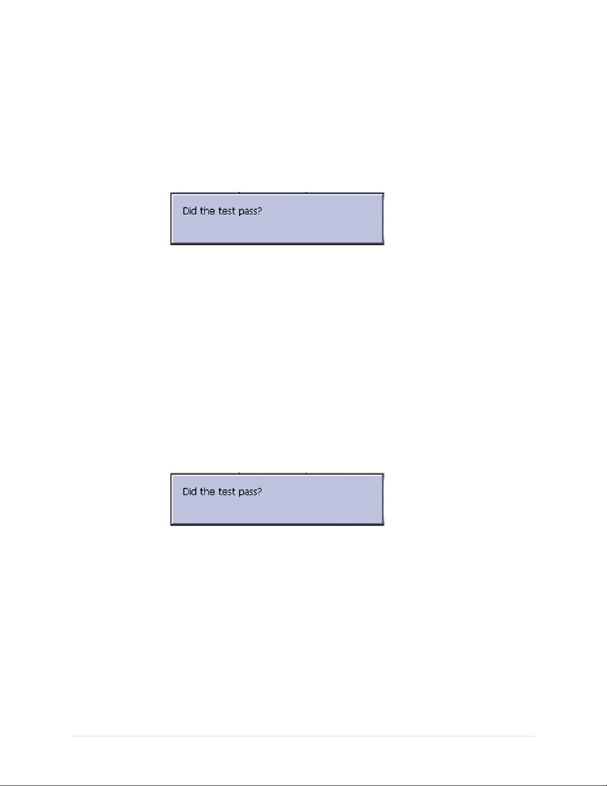
Thefollowingwindowopens:
4.PerformtheCOMPortLoopBackTestonCOM1.
a.SelectCOM1,pressEnter.
TheresultsoftheCOMPortLoopBackTestaredisplayed.
b.NotetheresultsoftheCOMPortLoopBackTest.
5.PerformtheCOMPortLoopBackTestonCOM2.
Troubleshooting
TestingtheLANOption
a.Usethepapercliptoshortpins2and3ontheCOMBconnector.
b.SelectCOM2,pressEnter.
TheresultsoftheCOMLoopBackTestforCOM2aredisplayed.
c.NotetheresultsoftheCOMLoopBackTestforCOM2.
6.Whenthetestisdone,pressEscorF6(Cancel)toclosetheresultswindow.
Ifeithertestfailed,replacethemainboard/ETEmoduleasdescribedin“”onpage.
UsetheLANTesttotestnetworkconnectivity.
1.ConnectthedevicetoanactiveLAN.
EnsurethattheLANisanactivenetwork.Ifyouconnecttoaninactivenetwork
tap,thetestresultmaybeafalsenegative.
2.OpentheDiagnosticTestswindowasdescribedin“AccessingtheSystem
DiagnosticsFunction”onpage33.
3.SelectLANTest.
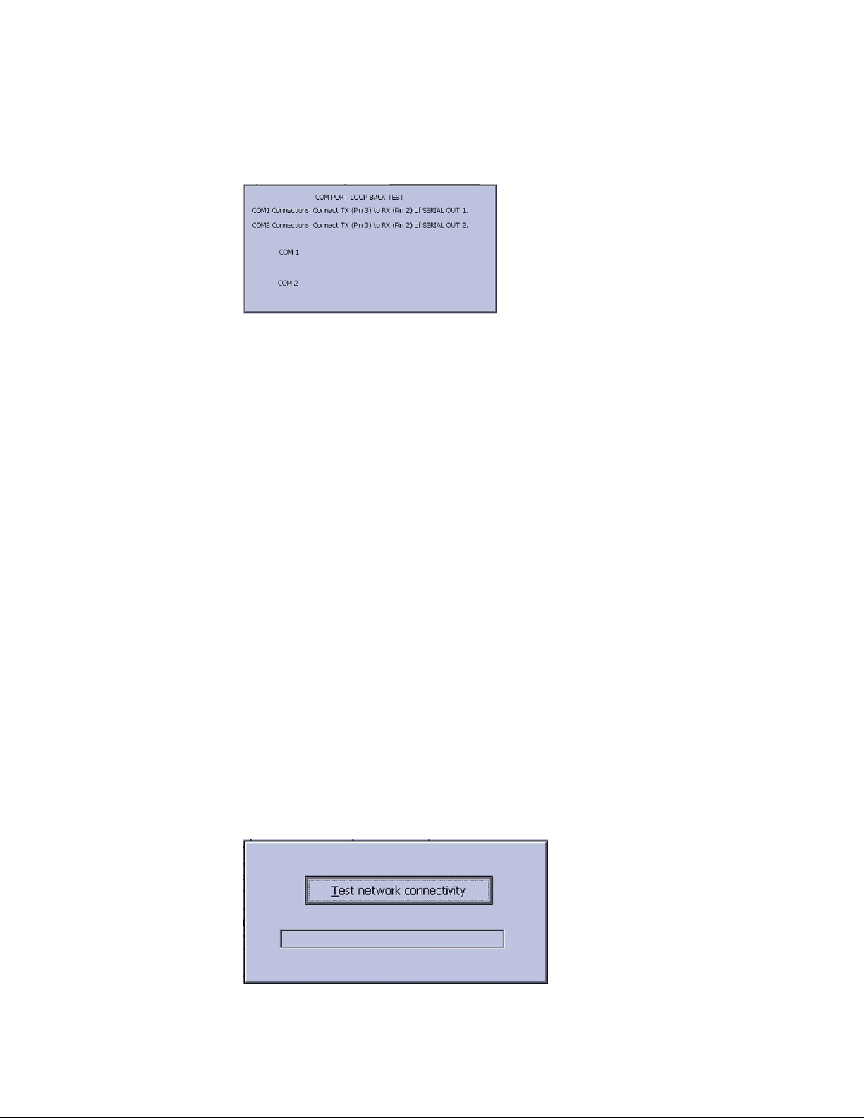
Thefollowingwindowopens:
4.PressEntertoselectTestnetworkconnectivity.
Thefollowingmessageisdisplayed:Checkingconnectivity.Pleasewait.
2028451-183EMAC™1600
43

Troubleshooting
TestingtheModem
Thenthetestresultsaredisplayed.
•Ifthefollowingmessageisdisplayedinthewindow,thetestpasses:System
ConnectedtoNetwork.
•Ifthefollowingmessageisdisplayedinthewindow,andyouaresurethe
deviceisconnectedtoanactivenetwork,thetestfails:NetworkUnavailable.
5.Whenthetestisdone,pressEscorF6(Cancel)toclosetheresultswindow.
Ifthetestfailed,replacethemainboard/ETEmoduleasdescribedin“”onpage.
UsetheModemTesttotesttheinternalandtheexternalmodem.
1.Connectthedevicetoanactiveanalogphoneline.
Ensurethatthephonelineisactive.Ifyouconnecttoaninactivephoneline,
thetestresultmaybeafalsenegative.
2.OpentheDiagnosticTestswindowasdescribedin“AccessingtheSystem
DiagnosticsFunction”onpage33.
TestingtheInternalModem
3.SelectModemTest.
Thefollowingwindowopens:
Testtheinternalmodemasdescribedinthefollowingsteps:
1.SelectInternalModemTest,pressEnter.
Thefollowingmessageisdisplayedinthewindow:TestinProgress.Please
wait.
Thentheresultsofthetestaredisplayed.
•Thetestpassesifthefollowingmessageisdisplayedinthewindow:Passed.
•Thetestfailsifthefollowingmessageisdisplayedinthewindow:Failed.
IftheInternalModemTestfails,replacetheinternalmodemasdescribedin
“ReplacingtheInternalModem(Option)”onpage71.
2.Whenthetestisdone,pressF6(Cancel)toclosetheresultswindow.
TestingtheExternalModem
44
Ifthesystemhasanexternalmodem,continuewith“TestingtheExternalModem”.
Testtheexternalmodemasdescribedinthefollowingsteps:
1.SelectExternalModemTest,pressEnter.
Thefollowingmessageisdisplayedinthewindow:TestinProgress.Please
wait.
MAC™16002028451-183E

Thentheresultsofthetestaredisplayed.
•Thetestpassesifthefollowingmessageisdisplayedinthewindow:Passed.
•Thetestfailsifthefollowingmessageisdisplayedinthewindow:Failed.
IftheExternalModemTestfailed,replacetheexternalmodem.
2.Whenthetestisdone,pressEscorF6(Cancel).
TestingtheUSBPort
UsetheUSBTesttotesttheUSBport.
1.OpentheDiagnosticTestswindowasdescribedin“AccessingtheSystem
DiagnosticsFunction”onpage33.
2.ConnectaUSBkeyboardtotheUSBportontherearpanelofthedevice.
NOTE:
TheUSBkeyboardusedforthistestmustmatchthelanguagethatis
selectedinsetup.
3.SelectUSBTest.
Troubleshooting
Thefollowingwindowopens:
4.PressanykeyontheUSBkeyboardandverifypassorfail:
•IfthecharacterthatappearsintheCharacterInputeldmatchesthekey
youpressed,thetestpassed.
•Ifthecharacterdoesnotmatchthekeyyoupressed,ornocharacterappears
intheCharacterInputeld,thetestfailed.
5.Whenthetestisdone,pressEscorF6(Cancel).
Thefollowingwindowopens:
6.Ifthetestpassed,pressF4(Yes)
Ifthetestfailed,pressF5(No).
Ifthetestfailed,replacethemainboard/ETEmoduleasdescribedin“”onpage.
2028451-183EMAC™1600
45

Troubleshooting
TestingthePatientLeadWires
Usethefollowingproceduretotestthepatientleadwires:
1.OpentheDiagnosticTestswindowasdescribedin“AccessingtheSystem
DiagnosticsFunction”onpage33.
2.Connectapatientcablewithleadwirestothedevice’spatientcableconnector.
3.Connectallleadstoapatientsimulatororshortingbar.
4.SelectPatientLeadWireCheck.
Thefollowingwindowopens:
5.PressEntertoselectStartTest.
Thetestresultsaredisplayedforeachleadwire.
•Ifthefollowingmessageisdisplayed,theleadwirepassedthetest:
Connected.
•Ifthefollowingmessageisdisplayed,theleadwirefailedthetest:
Disconnected.
6.whenthetestisdone,pressEscorF6(Cancel).
7.Replaceeveryleadwirethatfailedthetest.
8.Repeatthetest.
Iftheleadwirestillfailsthetest,replacetheacquisitionboardasdescribedin
“ReplacingtheAcquisitionBoardAssembly”onpage75.
EquipmentProblems:ECGDataNoise
IftheacquiredECGdatadisplaysunacceptablenoiselevels:
•Besuretheproblemisnotcausedbypoorskinpreparation,placement,orcondition
oftheelectrodeswhentroubleshootingnoiseorsignalquality.
•Carefulskinpreparationisthekeytoaninterference-freeECG.
•SignalqualityisindicatedusingHookupAdvisor.
46MAC™16002028451-183E

•Checkfordefectiveordate-expiredelectrodes.
•Checkfordefective,broken,ordisconnectedleadwires.
•Runthe“”onpagetoensurethatallleadwirespassthenoisetest.
ErrorCodes
Noactionisnecessaryforisolatederroroccurrences.However,iftheunitis
malfunctioningandanyofthefollowingerrormessagesarerepeatingand
unrecoverable,replacetheFRUsintheorderlisted.
AcquisitionErrorCodes
Wheremultiplesolutionsaresuggested,performthesuggestedactionsintheorder
given.Onceasolutionrestoresfunctionality,donotattemptthenextsolutioninthe
list.
Troubleshooting
YoucanturnHookupAdvisoronoroffintheECGmenu.SelectSystemSetup>
ECG>ECGAcquisition.
AcquisitionErrorCodes
ErrorCodeCauseSolution
AcquisitionError
-4
AcquisitionError
-3
AcquisitionError
-2
Invalidcommandsentto
acquisitiondriver
Acquisitionbufferoverow
Acquisitionmodulenot
connectedordetected
1.Checkthecables.
2.Selfcorrectinginternalerror.
3.Reloadtheapplicationsoftware.
1.Checkthecables.
2.ReplacetheCABLEASSYMAC1600
ACQTOMAINBOARDfoundinthe
CableHarnessKit,(PN2035707).
3.ReplacetheASSYACQUISITIONBOARD
MAC1600(2035705-001).
4.ReplacetheASSYMAC1600
MAINBOARDANDETEMODULE
(2035704-001).
1.Checkthecables.
2.ReplacetheCABLEASSYMAC1600
ACQTOMAINBOARDfoundinthe
CableHarnessKit(PN2035707).
3.ReplacetheASSYACQUISITIONBOARD
MAC1600(2035705-001).
4.ReplacetheASSYMAC1600
MAINBOARDANDETEMODULE
(2035704-001).
2028451-183EMAC™1600
47

Troubleshooting
AcquisitionErrorCodes(cont'd.)
ErrorCodeCauseSolution
AcquisitionError
-1
AcquisitionError
2
AcquisitionError
3
GeneralAcquisitionerror
Synchronizationerrorin
100msECGPacket
SequenceNumbererrorin
100msECGPacket
1.Checkthecables.
2.ReplacetheCABLEASSYMAC1600
ACQTOMAINBOARDfoundinthe
CableHarnessKit(PN2035707).
3.ReplacetheASSYACQUISITIONBOARD
MAC1600(2035705-001).
4.ReplacetheASSYMAC1600
MAINBOARDANDETEMODULE
(2035704-001).
1.Checkthecables.
2.ReplacetheCABLEASSYMAC1600
ACQTOMAINBOARDfoundinthe
CableHarnessKit(PN2035707).
3.ReplacetheASSYACQUISITIONBOARD
MAC1600(2035705-001).
4.ReplacetheASSYMAC1600
MAINBOARDANDETEMODULE
(2035704-001).
1.Checkthecables.
2.ReplacetheCABLEASSYMAC1600
ACQTOMAINBOARDfoundinthe
CableHarnessKit(PN2035707).
3.ReplacetheASSYACQUISITIONBOARD
MAC1600(2035705-001).
4.ReplacetheASSYMAC1600
MAINBOARDANDETEMODULE
(2035704-001).
AcquisitionError
4
Checksumerrorin100ms
ECGPacket
1.Checkthecables.
2.ReplacetheCABLEASSYMAC1600
ACQTOMAINBOARDfoundinthe
CableHarnessKit(PN2035707).
3.ReplacetheASSYACQUISITIONBOARD
MAC1600(2035705-001).
4.ReplacetheASSYMAC1600
MAINBOARDANDETEMODULE
(2035704-001).
AcquisitionError
7
Acquisitionselftesterror
1.Checkthecables.
2.ReplacetheASSYACQUISITIONBOARD
MAC1600(2035705-001).
48MAC™16002028451-183E

AcquisitionErrorCodes(cont'd.)
ErrorCodeCauseSolution
Troubleshooting
AcquisitionError
8
AcquisitionError
9
AcquisitionError
10
Errorloadingthe
acquisitionrmware
Acquisitiondriverfailedto
open
Acquisitiondriver
communicationerror
1.Reloadtheapplicationsoftware.
2.ReplacetheCABLEASSYMAC1600
ACQTOMAINBOARDfoundinthe
CableHarnessKit(PN2035707).
3.ReplacetheASSYACQUISITIONBOARD
MAC1600(2035705-001).
4.ReplacetheASSYMAC1600
MAINBOARDANDETEMODULE
(2035704-001).
1.ReplacetheCABLEASSYMAC1600
ACQTOMAINBOARDfoundinthe
CableHarnessKit(PN2035707).
2.ReplacetheASSYACQUISITIONBOARD
MAC1600(2035705-001).
3.ReplacetheASSYMAC1600
MAINBOARDANDETEMODULE
(2035704-001).
1.ReplacetheCABLEASSYMAC1600
ACQTOMAINBOARDfoundinthe
CableHarnessKit(PN2035707).
2.ReplacetheASSYACQUISITIONBOARD
MAC1600(2035705-001).
3.ReplacetheASSYMAC1600
MAINBOARDANDETEMODULE
(2035704-001).
AcquisitionError
11
Acquisitionrmwarele
notfound
Reloadtheapplicationsoftware
PrinterErrorCodes
PrinterErrorCodes
ErrorCode
PrinterInternalError1Printerrmwaredetectedan
error
PrinterInternalError2Printheadtemperatureistoo
hotortoocoldtoprint
2028451-183EMAC™160049
Cause
ReplacethePrinterAssembly
FRU(PN2035702-001).
1.ReplacethePrintHead
2.ReplacethePrinter
Solution
MAC1200WRITER
-SHECTPH,(PN
2036817-001).
AssemblyFRU(PN
2035702-001).

Troubleshooting
PrinterErrorCodes(cont'd.)
ErrorCode
PrinterInternalError3Printerdrivercouldnotbe
opened
PrinterInternalError4Printerdrivercommunication
error
PrinterInternalError5Printerdrivertimeouterror
PrinterInternalError6Printerdrivermiscellaneous
error
Cause
Solution
1.Checkthecables.
Replacethecablesif
necessary.
2.ReplacethePrinter
AssemblyFRU(PN
2035702-001).
1.Checkthecables.
Replacethecablesif
necessary.
2.ReplacethePrinter
AssemblyFRU(PN
2035702-001).
1.Checkthecables.
Replacethecablesif
necessary.
2.ReplacethePrinter
AssemblyFRU(PN
2035702-001).
1.Checkthecables.
Replacethecablesif
necessary.
2.ReplacethePrinter
AssemblyFRU(PN
2035702-001).
PrinterInternalError7Undenedprinterstatuswas
received
1.Checkthecables.
2.ReplacethePrinter
FrequentlyAskedQuestions
Thissectionaddressesfrequentlyaskedquestionsconcerningmaintenance,system
setup,andclinicaltopics.
Maintenance
Thissectionanswersquestionsregardingmaintenanceissuesforthesystem.
NOTE:
RefertotheSystemCongurationinformationintheOperator’sManualforthis
device.
50MAC™16002028451-183E
Replacethecablesif
necessary.
AssemblyFRU(PN
2035702-001).

SavingSystemSetupstoanSDCard
Q:HowdoIsavechangesIhavemadetotheSystemConguration?
A:Performthefollowingsteps:
1.InsertanSDcardintotheSDcardslotinthebackpanel,asshowninthe
followingillustration:
Troubleshooting
RestoringSystemSetups
2.PushtheSDcardintotheslottoseatitinplace.
3.OntheMainMenu,pressF5(SystemConguration).
4.PressF6(More)>F6(More)>F3(ExportSetup).
5.Onthelistonleftsideofthewindow,highlightthesetupleyouwanttosaveto
theSDcard.
6.PressF1(Export).
TheCongurationwassuccessfullyexportedwindowopens.
7.PressF6(OK).
8.EjecttheSDcardbypushingitinonce.
Storeitinasecurelocation.
Q:HowdoIrestoresystemsetupsfromtheSDcard?
A:Performthefollowingsteps:
1.InserttheSDcardintotheSDcardslotinthebackpanelasdescribedpreviously.
2.OntheMainMenu,pressF5(SystemConguration).
2028451-183EMAC™160051

Troubleshooting
3.PressF6(More)>F6(More)>F2(ImportSetup).
4.Onthelistonrightsideofthewindow,highlightthesetupleyouwanttoimport
fromtheSDcard.
5.PressF1(Import).
TheCongurationwassuccessfullyimportedwindowopens.
6.PressF6(OK).
7.EjecttheSDcardbypushingitinonce.
Storeitinasecurelocation.
PrintingaSystemSetupReport
Q:HowdoIobtainaprintedrecordoftheSystemCongurationle?
A:Performthefollowingsteps:
1.OntheMainMenu,pressF5(SystemConguration).
2.PressF6(More)>F3(PrintSetupReport).
3.SelectCompleteSetupandpressEnter.
OptionCodes
StoringECGs
4.Savetheprintedsetupreportinasecurelocation.
Youcanusethesavedsetupasareferenceifyouneedtorestorethesystem
setupmanually.
Q:Ineedtore-activatetheoptionsonmydevice.WherecanIndtheoptioncodes?
A:TheoptioncodesforthedevicearenotpartoftheSystemCongurationsettings.
Thesecodesarelistedonthelastpageofyourprintedsetupreport.Theyarealso
foundonalabelnexttothebatterycompartment.
Theprintedlistofoptioncodesisamoreconvenientaidtousewhenyouneedto
re-enterthesecodesafterinstallinganewmainboard.
Q:Whywon'tanyoftheECGsIperformsavetotheSDcard?
A:Verifythefollowing:
•TheSDcardisfullyinsertedintothedrive.
•YouareusingasupportedSDcard.
Referto“MAC1600UpperLevelAssembly,PN2032093”onpage110foralistof
supportedcards.
•TheSDcardisnotwrite-protected.
•TryanewSDcard.
•Yoursystemissetuptoautomaticallysaverecords.
•Ifyoursystemisnotsetuptoautomaticallysaverecords,youpressedStore.
Cleaning
Q:ShouldIcleanthedevice?
52MAC™16002028451-183E

BatteryCapacity
MACAddress
Troubleshooting
A:Cleantheexteriorsurfacesofalltheequipmentandperipheraldevicesmonthly,or
morefrequentlyifneeded.
1.Useaclean,softclothandamilddishwashingdetergentdilutedinwater.
2.Wringtheexcesswaterfromthecloth.
Donotdripwater,oranyliquid,onthewriterassembly,andavoidcontactwith
openvents,plugs,andconnectors.
3.Drythesurfaceswithacleanclothorpapertowel.
Q:Whatisthecapacityofthebattery?
A:GEHealthcarerecommendsthatyouconnectthedevicetoACpowerthroughawall
outletwheneveritisnotinuse.IfyouareoperatingthedeviceoffACpower,beaware
thatafully-chargedbatteryiscapableoftakingapproximately50ormoreECGswith
one-pageprintedreports,orthreehoursofcontinuousoperation(withoutprinting).
SystemSetup
LocationNumber
Q:IneedtoprovidetheMACaddressofthedevicetothenetworkadministratorto
enabletheLANcommunicationoption.HowdoIobtaintheMACaddress?
A:FollowthesestepstoobtaintheMACaddress:
1.OpentheDIAGNOSTICTESTSwindowasdescribedin“AccessingtheSystem
DiagnosticsFunction”onpage33.
2.SelectServiceReportandpressEnter.
3.FindtheMACaddressontheprintedservicereport.
Thissectionanswersquestionsregardingsystemsetupforthesystem.
Q:Whenenteringinthepatientdata,howdoIgettheLocationeldtoautomatically
populatewiththesamenumber?
A:YoucansettheLocationnumberinBasicSetupsoyoudonotneedtoenterit
foreachtest.
1.OntheMainMenu,pressF5(SystemConguration).
2.PressF1(BasicSetup).
3.UsetheTrimpadtomovethecursortotheLocationeld.
4.TypethedesiredLocationnumber.
5.PressF6(Save)>F5(MainMenu).
PatientQuestions
Q:HowdoIchangethequestionsIseewhenIamenteringthepatientdata?
2028451-183EMAC™1600
53

Troubleshooting
A:ThepatientquestionsyouseeonthePatientDatawindowwhenstartingatest
weresetupinPatientSetup.
1.OntheMainMenu,pressF5(SystemConguration).
2.PressF6(More)>F4(PatientSetup)>F4(PageDown).
3.SelectExtraQuestions...andpressEnter.
TheExtraQuestionswindowopens:
Passwords
4.ForeachextraquestionyouwishtoaskinthePatientDatawindow:
a.TypethePrompt.
b.SelectthetypeofquestionfromtheTypelist:
•Alphanumeric
•Numeric
•Yes/No/Unknown
5.IntheExtraQuestions...window,pressF6(Save).
6.IntheTestInformationSetupwindow,pressF6(Save).
7.ReturntotheMainMenu.
Q:ThesystemwassetupforHighSecurityModeandIforgotmypassword.HowdoI
accessthesystem?
A:Usethefollowingstepstoaccessthesystem:
1.ContactGEHealthcareTechnicalSupportandprovidetheserialnumberof
thedeviceyouwanttoaccess.
GEHealthcareTechnicalSupportwillgenerateatemporary,device-specic
nameandpasswordthatyoucanusefor24hours.
2.LogintothesystemwiththeuserIDMACServiceandthepasswordprovided
byGEHealthcareTechnicalSupport.
NOTE:
IfthekeyboardontheunitdoesnotincludethelettersfortheMACService
userID,type6227378423fortheuserID.
3.Immediatelyafterloggingintothesystem,verifyyourdevice’susernameand
password.
4.Recordthisinformationandstoreitinasecurelocationforfuturereference.
54
MAC™16002028451-183E

Clinical
Thissectionanswersquestionsregardingclinicalissuesforthesystem.
RestingECGReportFormat
Q:HowdoIchangethewayanECGlooks(format)whenitprintsout?
A:FollowthesestepstochangetheECGformat:
1.OntheMainMenu,pressF5(SystemConguration).
2.PressF2(RestingECG).
3.PressF4(PageDown)twotimes.
4.SelectaLeadSequenceandRhythmLeads.
5.PressF6(Save).
Editing
Q:Canyouedittheinterpretationatthedeviceandthentransmittheeditedrecordto
theMUSEsystemasanunconrmedrecord?
Troubleshooting
A:Ifyoueditdemographicinformation,onlytherecordisstilltransmittedtotheMUSE
systemasanunconrmedrecord.
Ifyouedittheinterpretation,thedataisnotsavedunlesstherecordisconrmedat
thedevice.TherecordistransmittedtotheMUSEsystemasaconrmedrecord.
NavigatingtheUserInterface
Q:HowdoInavigatefromtheStartupscreentotheMainMenu?
A:Youcancongurethesysteminanumberofdifferentways.Someofthese
congurationchoicesdeterminetheactionsthatyouneedtoperforminorderto
proceedfromthepowerupdisplaytotheMainMenu.
2028451-183EMAC™1600
55

Troubleshooting
Therearethreecongurationsthatdeterminetheinitialwindowthatopensatpower
upandwhatactionsyouneedtoperformtonavigatetotheMainMenu:
•WhenPowerupmodeiscurrentlyselectedinBasicSetup.
•WhenHighSecurityModeisenabledinBasicSetup.
•WhetherornottheUSBBarcodeReadersupportoptionisactivated.
Thevariousstepsinthissectiondescribehowtonavigatefromthepowerupscreen
totheMainMenuforthevarioussystemcongurations.Usethestepsthatapply
toyoursystemcongurationsettings.
•IfyoursystemisconguredtopowerupintheRestingECGmode,goto“Resting
ECGPowerUpMode”onpage57.
•IfyoursystemisconguredtopowerupintheArrhythmiamode,goto“Arrhythmia
PowerUpMode”onpage57.
•IfyoursystemisconguredtopowerupintheMainScreenmode,goto“Main
ScreenPowerUpMode”onpage58.
•IfyoursystemisconguredtopowerupintheStressECGmode,goto“StressECG
PowerUpMode”onpage58.
56MAC™16002028451-183E

RestingECGPowerUpMode
ThesestepsdescribehowtonavigatetotheMainMenuafterpoweringonthedevice
whenRestingECGisselectedforPowerupmodeinBasicSetup.
NOTE:
Ifyouneedtoperformsystemsetupfunctions,besureyouloginasauserwhois
assignedsetupeditingprivileges.
1.IftheHighSecurityModeisenabled,proceedwithstepsathroughcafterthe
2.PressF5(Cancel)>F6>(More)>F5(MainMenu).
Troubleshooting
windowopenspromptingforaUserIDandPassword.
Ifthepasswordpromptisnotdisplayed,gotostep2.
a.TypeyouruserIDintheUserIDeld.
b.PressEnterorthedownarrowontheTrimpadtomovethecursorto
thePasswordeld.
c.TypeyourpasswordinthePasswordeld.
d.PressF5(Login).
ArrhythmiaPowerUpMode
ThesestepsdescribehowtonavigatetotheMainMenuafterpoweringonthedevice
whenArrhythmiaisselectedforPowerupmodeinBasicSetup.
NOTE:
Ifyouneedtoperformsystemsetupfunctions,besureyouloginasauserwhois
assignedsetupeditingprivileges.
1.IftheHighSecurityModeisenabled,proceedwithstepscthroughcafterthe
2.PressF6(Cancel).
windowopenspromptingforaUserIDandPassword.
Ifthepasswordpromptisnotdisplayed,gotostep2.
a.TypeyouruserIDintheUserIDeld.
b.PressEnterorthedownarrowontheTrimpadtomovethetothe
Passwordeld.
c.TypeyourpasswordinthePasswordeld.
d.PressF5(Login).
Ifthebarcodereaderoptionisenabled,awindowopensprompting
youtoScanthePatientbarcode.
NOTE:
Ifthebarcodepromptisnotdisplayed,gotostep3.
3.PressF5(Cancel)>F6(More)>F5(MainMenu).
2028451-183EMAC™1600
57

Troubleshooting
MainScreenPowerUpMode
ThesestepsdescribehowtonavigatetotheMainMenuafterpoweringonthedevice
whenMainScreenisselectedforPowerupmodeinBasicSetup.
NOTE:
Ifyouneedtoperformsystemsetupfunctions,besureyouloginasauserwhois
assignedsetupeditingprivileges.
1.IfHighSecurityModeisenabled,proceedwithstepscthroughcafterthe
windowopenspromptingforaUserIDandPassword.
Ifthepasswordpromptisnotdisplayed,gotostep2.
a.TypeyouruserIDintheUserIDeld.
b.PressEnterorthedownarrowontheTrimpadtomovethecursorto
c.TypeyourpasswordinthePasswordeld.
d.PressF5(Login).
thePasswordeld.
TheMainMenuisdisplayed.
2.IfthesystemisconguredforMainScreenPowerupmodeanddoesnothave
StressECGPowerUpMode
ThesestepsdescribehowtonavigatetotheMainMenuafterpoweringonthedevice
whenStressECGisselectedforPowerupmodeinBasicSetup.
1.IfHighSecurityModeisenabled,proceedwithstepscthroughcafterthe
theHighSecurityModeenabled,theMainMenuisdisplayedafterpowering
upthesystem.Youdonotneedtopressanyotherkeysinordertodisplaythe
MainMenu.
windowopenspromptingforaUserIDandPassword.
Ifthepasswordpromptdoesnotappear,gotostep2.
NOTE:
Ifyouneedtoperformsystemsetupfunctions,besureyoulogin
asauserwhoisassignedsetupeditingprivileges.
a.TypeyouruserIDintheUserIDeld.
b.PressEnterorthedownarrowontheTrimpadtomovethecursorto
thePasswordeld.
c.TypeyourpasswordinthePasswordeld.
d.PressF5(Login).
Ifthebarcodereaderoptionisenabled,awindowopensprompting
youtoScanthePatientbarcode.
2.PressF6(Cancel).
NOTE:
Ifthebarcodepromptisnotdisplayed,gotostep3.
3.PressF5(Cancel)>F6(More)>F6(More)>F5(MainMenu).
58MAC™16002028451-183E

Maintenance
Regularmaintenance,irrespectiveofusage,isessentialtoensurethattheequipment
isalwaysfunctionalwhenrequired.Thischapteraddressesmaintenanceprocedures
andrecommendations.
RecommendedMaintenance
Refertotheoperator’smanualforyoursystemforcleaningprocedures.Thesystem
doesnotrequireanycalibrationprocedures.GEHealthcarerecommendsthatyou
performelectricalsafetychecksannually.
WARNING:
EQUIPMENTFAILUREANDHEALTHHAZARDSFailureonthepartofallresponsible
individuals,hospitalsorinstitutions,employingtheuseofthissystem,to
implementtherecommendedmaintenanceschedule,maycauseequipment
failureandpossiblehealthhazards.
4
Thesoleresponsibilityrestswiththeindividuals,hospitals,orinstitutionsutilizing
thesystem.
Themanufacturerdoesnotinanymanner,assumetheresponsibilityfor
performingtherecommendedmaintenanceschedule,unlessanEquipment
MaintenanceAgreementexists.
RequiredToolsandSupplies
Thefollowingtoolsarerequiredtoperformtheproceduresdescribedinthischapter:
•ECGsimulator
•Smallatbladescrewdriver
•PosidriverPZ1x80
•PosidriverPZ2x100
•Currentleakagetester
•Anti-staticwriststrap
•Smallsidecutterpliers
•Smallneedle-nosepliers
•LargepapercliporsmalldiameterAllenwrench
•Smalladjustablewrench
2028451-183EMAC™160059

Maintenance
•MAC™1600RestingECGAnalysisSystemServiceManual
•MAC™1600RestingECGAnalysisSystemOperator’sManual
FRUReplacementProcedures
ThissectiondescribestheFieldReplaceableUnits(FRUs)thatarepartofyoursystem.
HighLevelFRUIdentication
Item
1
papertrayassembly
2
internalmodem(option)
3
display
4
keyboard
5
battery
6
barcodereader(option)
60MAC™16002028451-183E
Description
Maintenance
Item
7
8
9
10
11
12
13
14
PreparingSystemforFRUReplacement
Priortoperforminganydisassemblyprocedures,performthefollowingsteps:
NOTE:
Takestrictprecautionsagainstelectrostaticdischargedamagewhilereplacingeld
replaceableunits.
Description
patientcable
baseplasticassembly
middleplasticassembly
KISSpump(option)
mainboardETEassembly
powersupplyassembly
printerassembly
acquisitionmoduleassembly
1.Poweroffthesystem.
2.DisconnectthedevicefromtheACwalloutlet.
3.Disconnectthepowercordfromtherearpanelconnector .
4.Disconnectthepatientcablefromthedeviceasdescribedin“Replacingthe
PatientCable”onpage61.
5.Removethepapertrayassemblyasdescribedin“ReplacingthePaperTray
Assembly”onpage64.
6.Removethebatteryasdescribedin“ReplacingtheBattery”onpage64.
ReplacingthePatientCable
1.DisconnectthesystemfromACpower.
2.Disconnectthepatientcablefromthesidepanelconnectorasshowninthe
followingillustration.
2028451-183EMAC™160061

Maintenance
3.Connectanewpatientcabletosidepanelconnector .
4.Performtheapplicablecheckoutprocedures.
Referto“FunctionalCheckout”onpage99.
ReplacingBarcodeReaderorBarcodeReaderCable
Usethefollowingproceduretoreplacethebarcodereadercable.
1.PoweroffthesystemanddisconnectitfromACpower .
2.DisconnectthebarcodereaderfromtheUSBconnectorontherearpanelas
showninthefollowingillustration.
62MAC™16002028451-183E

3.Ifyouareonlyreplacingthecable,disconnectthecablefromthebarcode
readerasshowninthefollowingillustration.
a.InsertanAllenwrench(orstraightenedpaperclip)inthesmallholeinthe
baseofthebarcodereader.
Maintenance
b.Whilepushingthetoolintothehole,pullthecabletoremoveitfrom
thebaseofthebarcodereader .
4.Usinganewcable,reversethedisassemblyprocedurestoreassemblethecable.
InserttheUSBconnectorwiththeUSBsymbolfacingdown.
5.Congurethenewbarcodereaderasdescribedintheoperator’smanualfor
yoursystem.
6.Performtheapplicablecheckoutprocedures.
Referto“FunctionalCheckout”onpage99.
2028451-183EMAC™160063

Maintenance
ReplacingthePaperTrayAssembly
Usethefollowingproceduretoreplacethepapertrayassemblyofyoursystem.
1.DisconnectthesystemfromACpower.
2.Pressdownonthepapertrayreleasebuttonandpullupontherollerholder.
3.Pulloutthepapertrayuntilitstops.
4.Pressandholdthereleasetab(1)onthebaseplastic.Thenpullthepapertrayto
removeitcompletelyfromthedevice.
5.Reassemblethepapertrayassemblybyreversingthestepsforremoval.
6.Performtheapplicablecheckoutprocedures.
Referto“FunctionalCheckout”onpage99.
ReplacingtheBattery
Usethefollowingproceduretoreplacethebatteryinyourdevice.
1.DisconnectthesystemfromACpower.
2.Removethepapertrayassemblyasdescribedin“ReplacingthePaperTray
Assembly”onpage64.
64MAC™16002028451-183E

3.Turnthedeviceover.
4.Pressthebatteryreleasetab(1)andraisethebatteryfromitscompartment
toremoveit.
WARNING:
ENVIRONMENTALHAZARDImproperdisposalofthebatterycancause
environmentalandhealthhazards.
Maintenance
DoNOTdisposeofthebatterybyreorburning.
Followlocalenvironmentalguidelinesconcerningdisposalandrecycling.
5.Toinsertthenewbattery,lineupthetabsontheendofthebatterywiththeslots
ontheendofthebatterycompartment(1).
2028451-183EMAC™160065

Maintenance
6.Tiltthebatteryforwardandlowerituntilitlatchesintoplace.
7.Verifythatthebatteryisseatedrmlyinthecompartment.
Ifitisnotseatedrmly(1),pressthelatchuntilitsnapsintoplace(2).
66MAC™16002028451-183E
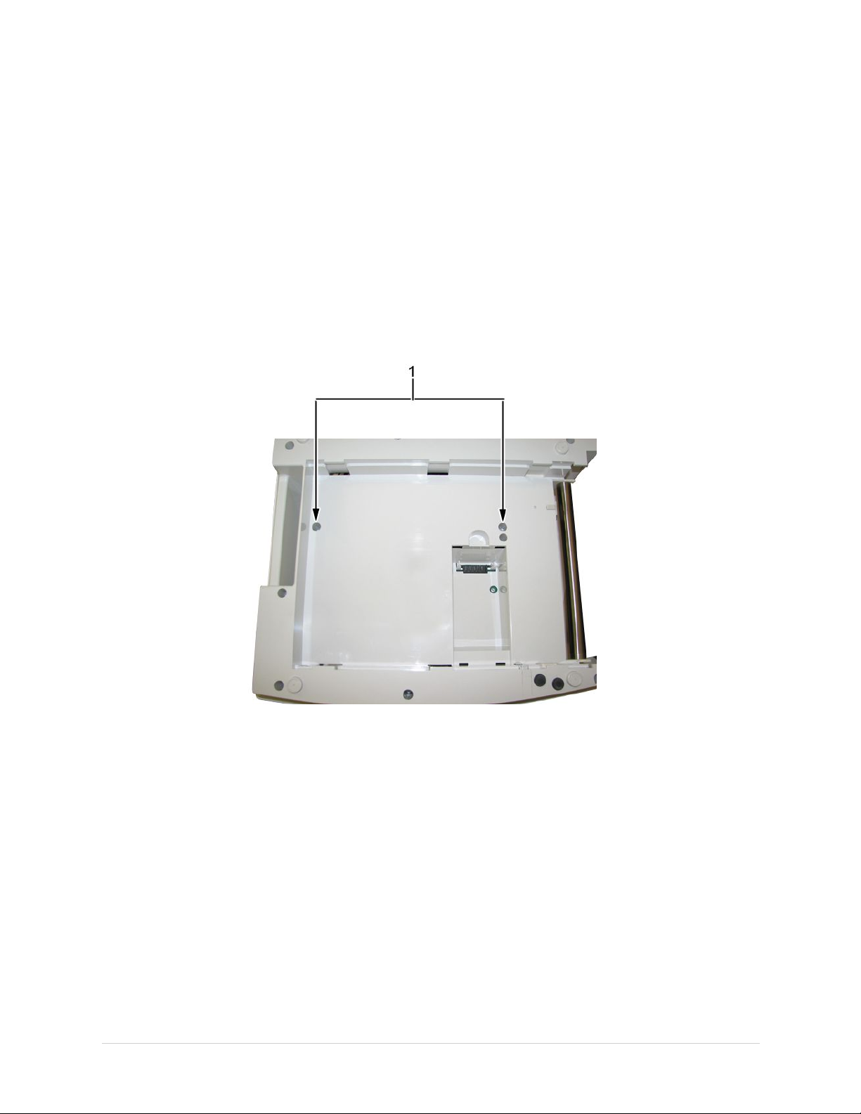
8.ConnectthedevicetoACpowerandpoweronthesystem.
9.Performtheapplicablecheckoutprocedures.
Referto“FunctionalCheckout”onpage99.
ReplacingtheKeyboard
1.DisconnectthesystemfromACpower.
2.Removethepapertrayasdescribedin“ReplacingthePaperTrayAssembly”
onpage64.
3.Removethebatteryasdescribedin“ReplacingtheBattery”onpage64.
4.Removethetwoscrews(1)fromthebottomofthedevice.
Maintenance
5.Turnthedeviceover,soitisrightsideup.
2028451-183EMAC™160067

Maintenance
6.PushasmallAllenwrench(orstraightenedpaperclip)intooneofthe
keyboardbezelreleaseholes(1),asshowninthefollowingillustration,while
pushinguponthecornerofthekeyboardbezel(2).
7.Repeatstep6fortheothercornerofthekeyboardbezel.
Thetwokeyboardbezelreleaseholes(1)areshowninthefollowingillustration.
8.Liftthebackendofthekeyboardbezelapproximatelyoneinch.
68MAC™16002028451-183E

9.Pushforwardonthebezel,inthedirectionindicatedbythearrowinthefollowing
illustration,tounlatchitstabsfromthefouralignmentholeslocatedatthefront
ofkeyboardbezel,toreleasetheitfromthedevice.
10.Removethekeyboardbezel.
11.Liftthekeyboardoutofthebezel.
Maintenance
12.Onthebacksideofthekeyboard,pulldownonthelock-releasetabs(1)oneach
sideofthekeyboardcableconnectorasshowninthefollowingillustration.
2028451-183EMAC™160069

Maintenance
13.Disconnectthekeyboardcableasshowninthefollowingillustration.
14.Removethekeyboard.
15.Reassembleanewkeyboardbyreversingthestepsforremoval.
Thefollowingsequenceofstepsdescribeshowtoreplacethekeyboardbezel.
a.Alignthefourtabs(1)atthefrontofthekeyboardbezelwiththefourholes
inthemiddleplastic.
b.Firmlypushthekeyboardbezeltabsintotheholes.
c.Pushdownoneachcornerattherearofthekeyboardbezeluntil
itsnapsintoposition.
16.Performtheapplicablecheckoutprocedures.
Referto“FunctionalCheckout”onpage99.
70MAC™16002028451-183E

ReplacingtheDisplayAssembly
1.DisconnectthesystemfromACpower.
2.Removethepapertrayasdescribedin“ReplacingthePaperTrayAssembly”
3.Removethebatteryasdescribedin“ReplacingtheBattery”onpage64.
4.Removethekeyboardbezelasdescribedin“ReplacingtheKeyboard”onpage
5.Removethefourscrews(1)thatholdthedisplayassemblyinplace.
Maintenance
onpage64.
67.
6.Liftthedisplayoutoftheassembly.
7.Reassemblethedisplaybyreversingthestepsforremoval.
8.Performtheapplicablecheckoutprocedures.
Referto“FunctionalCheckout”onpage99.
ReplacingtheInternalModem(Option)
1.DisconnectthesystemfromACpower.
2.Removethepapertrayasdescribedin“ReplacingthePaperTrayAssembly”
onpage64.
3.Removethebatteryasdescribedin“ReplacingtheBattery”onpage64.
2028451-183EMAC™160071

Maintenance
4.Carefullynotetheorientationandpositionofthemodemyouareaboutto
remove.
Thisinformationisneededwheninsertingthereplacementmodem.
5.Usingasmall,atbladescrewdriver,gentlylifteachendofthemodemto
releaseitspinsfromtheirsockets.
6.Usingyourngers,liftthemodemandremoveitfromthedevice.
7.Reassembletheinternalmodembyreversingthestepsforremoval.
a.Usethegureinstep4ofthisproceduretoorientandpositionthe
modeminthehole.
b.Visuallyalignthepinsonthemodemwiththesocketsonthemainboard.
c.Pushthemodemtoseatitinthesockets.
d.Ifthegapsbetweenthemodemandtheholedonotmatchthegure
instep4,removethemodemandrepeatthisstepuntilthemodemis
properlyseatedasshowninstep4.
8.Performtheapplicablecheckoutprocedures.
Referto“FunctionalCheckout”onpage99.
ReplacingthePowerSupplyAssembly
1.DisconnectthesystemfromACpower.
2.Removethepapertrayasdescribedin“ReplacingthePaperTrayAssembly”
onpage64.
3.Removethebatteryasdescribedin“ReplacingtheBattery”onpage64.
72MAC™16002028451-183E

4.Turntheunitoverandloosentheeightscrewsshowninthefollowingillustration.
5.Pullthebaseplastichousing(1)awayfromthemiddleplastichousing(2).
PushinwardontheACpowerconnector(3)whileseparatingthetwoassemblies.
Maintenance
2028451-183EMAC™1600
73

Maintenance
6.Liftthebackofthebaseplastic(1)fromthemiddleplastic(2),asshowninthe
followingillustration,untilyoucanaccessthetwocablesthatconnectthese
twoassemblies.
7.Disconnectthetwocablesfromthemainboard.
8.Setthebaseplasticassemblynexttothemiddleplasticassemblyasshownin
thefollowingillustrationandidentifythepowersupplyassembly(1).
9.Usingasmallneedle-nosepliers,disconnectpinkgroundconnectorfrom
ACoutlet.
10.Liftthepowersupplyassembly(Ainthepreviousgure)fromtherails.
11.Removethepowersupplyshield.
12.Disconnectthewhiteconnectorfromthepowersupplycircuitboardbypinching
thewhitetabwhilepullingtheconnector.
13.DisconnectthegroundingcablefromthebackoftheACpowerconnector .
14.Removethepowersupplyassembly.
74
MAC™16002028451-183E

15.Replacethepowersupplyassemblybyreversingthestepsforremoval.
Remembertoreplacethesnippedtiewrapwiththeoneprovidedinthe
powersupplyFRUkit.
16.Performtheapplicablecheckoutprocedures.
Referto“FunctionalCheckout”onpage99.
ReplacingtheAcquisitionBoardAssembly
1.Separatethemiddleplasticandbaseplasticassembliesasdescribedin
“ReplacingthePowerSupplyAssembly”onpage72,steps1through8.
2.Usingthefollowingillustration,identifytheacquisitionboardassembly(1).
Maintenance
3.DisconnectthegrayUSBconnectorfromtheacquisitionboardasshown
inthefollowingillustration.
2028451-183EMAC™1600
75

Maintenance
4.Removethetwoscrews(1)showninthefollowingillustration.
5.Lifttheacquisitionmoduleassemblyuntilyoucanaccesstheblackharness
connectorontheothersideoftheacquisitionmodule.
6.IfthesystemisequippedwiththeoptionalKISSpump,disconnectthegray
hosefromtheluertting.
7.Removetheacquisitionboardassembly.
8.Reassembletheacquisitionboardassembly.Ifthesystemdoesnothavethe
KISSoption,gotostep9.IfthesystemhastheKISSoption,gotostep10.
Usethefollowingillustrationforreference.
9.Reassembleacquisitionboardassembly(systemswithnoKISSoption).
a.Placethelabel(item36)intherecessedholeoftheplasticbezel.
b.Reversethedisassemblystepstoreassemble.
76MAC™16002028451-183E

10.Reassembleacquisitionboardassembly(systemswiththeKISSoption).
a.Reassembleitems37,38,and39intotheplasticbezelasshowninthe
previousillustration.
b.Tightentheplasticnutlock(item38)withasmalladjustablewrench.
c.Handtightentheluerplug(item39)ontotheluerconnector(item37).
d.Reconnectthegrayhosetotheluerconnector(item37).
e.Reversethedisassemblystepstoreassemble.
11.Performtheapplicablecheckoutprocedures.
Referto“FunctionalCheckout”onpage99.
ReplacingtheKISSPumpAssembly(Option)
1.Separatethemiddleplasticandbaseplasticassembliesasdescribedin
“ReplacingthePowerSupplyAssembly”onpage72,steps1through8.
2.Usingthefollowingillustration,identifytheKISSpumpassembly(1).
Maintenance
3.Turnthedeviceoverandremovethekeyboardbezel.
4.Removethetworearpanelscrews.
2028451-183EMAC™1600
77

Maintenance
5.Lifttherearbezelandpullitawayfromthedeviceinordertoreachthe
twoKISSpumphoses.
6.PullthetwoKISSpumphosesfromtheirconnectorsusingthesmallneedle-nose
pliers,ifnecessary.
7.Disconnectandremovethekeyboardasdescribedin“ReplacingtheKeyboard”
onpage67.
NOTE:
Removingthekeyboardisrecommendedtominimizestrainonthekeyboard
ribboncableduringtheremainingstepsinthisprocedure.
8.Turnthedeviceoverandremovetheacquisitionassemblyasdescribedin
“ReplacingtheAcquisitionBoardAssembly”onpage75.
NOTE:
Removingthisassemblyprovideseasieraccessfortheremovalofthehose
inthenextstep.
78MAC™16002028451-183E

Maintenance
9.Lifttheacquisitionassemblyandremovethetwoscrewsholdingthebezelto
theacquisitionassemblyasshowninthefollowingillustration.
10.Pullthegrayhosefromthebezelusingthesmallneedle-nosepliers,ifnecessary.
11.DisconnecttheKISSpumpconnectorfromthemainboard.
12.Removethethreemountingscrews.
13.RemovetheKISSpumpassembly.
14.ReassembletheKISSpumpassemblybyreversingthedisassemblysteps.
15.Performtheapplicablecheckoutprocedures.
Referto“FunctionalCheckout”onpage99.
2028451-183EMAC™160079

Maintenance
ReplacingthePrinterAssembly
Usetheproceduresinthissectiontoreplacetheprinterassembly.
RemovingthePrinterAssembly
1.Separatethemiddleplasticandbaseplasticassembliesasdescribedin
2.Usingthefollowingillustration,identifytheprinter(1).
3.Usingthesidecutterpliers,snipthetiewrap(2)thatholdstheprintercable
“ReplacingthePowerSupplyAssembly”onpage72,steps1through8.
harnesstothebaseplastic(3).
4.DisconnectthegrayUSBcablefromtheprinterboard.
5.Usingasmall,atbladescrewdriver,pullthereleasetabsoneachsideofthe
connectortodisconnectthequeuesensorribboncablefromtheprinterboard,
asshowninthefollowingillustration.
80MAC™16002028451-183E

6.Removethetwomountingscrewsthatholdtherightprintheadholderinplace.
Maintenance
7.Repeatstep6toremovethetwomountingscrewsontheleftprintheadholder.
2028451-183EMAC™160081

Maintenance
8.Carefullyslidetheprinterassemblyapproximately1/2inch(13mm)tothe
righttoprovideaccesstotheprintermotorconnector(1).
9.Lifttheprintermotorconnectorstraightuptoremoveitfromthebaseplastic.
10.Removetheprinterassemblyfromthebaseplastic.
82MAC™16002028451-183E

ReplacingthePrinterAssembly
Maintenance
Usethisproceduretoreplacetheprinterassembly.
1.Whileholdingthereplacementprinterassemblyasshowninthefollowing
illustration,routetheribboncable(1)betweentheprinterboardandthe
printhead.
2.Lowertheprinterassemblyinposition.
Placetheprintermotorconnectorintoitsguiderailswhileroutingthefourwires
inthechannel(1)asshowninthefollowingillustration.Ifthesewiresarenot
properlyroutedinthechannel,theywillbepincheduponreassembly.
3.Slidetheprinterassemblytoitsnalmountingposition.
2028451-183EMAC™160083

Maintenance
4.Replacetherstofthefourmountingscrews.
Ensurethewiresarenotpinched.Useasmallneedle-noseplierstoholdthe
screwwhiledrivingitintoplace.
5.Replacetheremainingthreemountingscrews.
6.Connecttheribboncabletotheprinterboard.
84MAC™16002028451-183E

7.Ensurethetwoqueuesensorribboncables(1)aretuckedinasshowninthe
following“AfterTucking”illustrationtopreventpinchingofthesecableswhen
reassemblingthemain(top)plasticassembly.
Maintenance
8.Reverseallremainingdisassemblystepstocompletethereassembly.
9.CongurethePrintheadResistanceasfollows:
a.FromtheMainMenu,pressF5(SystemConguration).
b.PressF6(More)>F6(More)>F5(ServiceSetup).
c.Whenprompted,entertheServicePassword.
Ifyoudonotknowthepassword,contactGEHealthcareTechnical
Support.
2028451-183EMAC™160085

Maintenance
d.SelectDeviceSettings.
e.InthePrintheadResistanceeld,type1000.
f.PressF6(Save).
10.Performtheapplicablecheckoutprocedures.
Referto“FunctionalCheckout”onpage99.
ReplacingthePrinterBoard
Usetheproceduresinthissectiontoremoveandreplacetheprinterboard.
RemovingthePrinterBoard
Usethefollowingproceduretoremovetheprinterboard.
1.Removetheprinterassemblyasdescribedin“RemovingthePrinterAssembly”
onpage80.
2.Releasethetopedgeoftheboardfromtheprintheadholderbypushingeach
releasetabinthedirectionofthearrowandpullingtheboardbacktothe
positionshowninthefollowingillustration.
3.Disconnectthequeuemarksensorribboncablefromtheprinterboard.
86MAC™16002028451-183E

4.Disconnectthesixgreengroundingcablesbyremovingthescrews(1)holding
theminplace.
Maintenance
5.Disconnectthewhiteribboncablebypushingtheconnectorsleeve(1)inthe
directionshowninthefollowingillustration.
6.Unplugthenarrowconnector(2)oftheharnessfromtheprintheadshowninthe
followingillustrationandremovetheprinterboard.
ReplacingthePrinterBoard
Usethefollowingproceduretoreplacetheprinterboard.
1.Reconnecttheblackharnesstotheprinterassemblyandtothereplacement
printerboard.
2.Reconnectthewhiteribbonconnectortotheprinterboard.
3.Securetheribboncablebyslidingthesleevetothelockedposition.
4.Reconnectthesixgroundingstraps.
5.Guidethequeuemarksensorribboncablebetweentheprinterboardandthe
printhead,andreconnecttheribboncabletotheprinterboard.
2028451-183EMAC™160087

Maintenance
ReplacingthePrinthead
RemovingthePrinthead
6.Placethebottomofprinterboardinthegroovesandsnapthetopedgeon
eachsidebackintoposition.
7.Followtheprinterassemblyreplacementproceduresasdescribedin“Replacing
thePrinterAssembly”onpage83.
8.Performtheapplicablecheckoutprocedures.
Referto“FunctionalCheckout”onpage99.
Usethefollowingprocedurestoremoveandreassembletheprinthead.
Usethefollowingstepstoremovetheprintheadfromtheprinter:
1.Removetheprinterboardasdescribedin“RemovingthePrinterBoard”on
page86.
2.Removethestainlesssteeltubebypushingoutwardontheprintheadholder
whilepushingthetubeasshowninthefollowingillustration.
3.Removethescrew(1)thatfastensthepressurestriptotheleftprintheadholder.
4.Removetheleftprintheadholderinthesamemanner.
88MAC™16002028451-183E

ReassemblingthePrinthead
Maintenance
5.Repeattheprevioustwostepsfortherightprintheadholder.
6.Disconnectthetwocables.
Usethefollowingproceduretoreassembletheprintheadintheprinter.
1.Inserttheprintheadassemblyintotherightprintheadholderbyslidingitunder
thetwotabs(1)showninthefollowingillustration.
2.Standtheassemblyontherightplasticprintheadholder(thesidewithnoqueue
sensor)andreassembletheleftprintheadholderbyperformingthefollowing
threestepssimultaneously:
a.Pushinonpressurebarwithyourthumb(1).
b.Pushdownontheplasticprintheadholderwithyourindexnger(2)
toalignthescrewholes.
c.Replacethescrew(3)thatholdsthepressurebartotheleftprinthead
holder.
2028451-183EMAC™160089

Maintenance
3.Reattachthethreecables(1)showninthefollowingillustration.
4.Reconnectthesixgroundingstraps.
5.Replacetheprinterboardasdescribedin“ReplacingthePrinterBoard”on
page86.
90MAC™16002028451-183E

Maintenance
6.Replacethestainlesssteeltubewiththenotchedend(1)onthesideshownin
thefollowingillustration.
7.Reassembletheprinterassemblytothemainassemblyasdescribedin
“ReplacingthePrinterAssembly”onpage83.
8.CongurethePrintheadResistanceasfollows:
a.OntheMainMenu,pressF5(SystemConguration).
b.PressF6(More)>F6(More)>F5(ServiceSetup).
c.Whenprompted,entertheServicePassword.
Ifyoudonotknowthepassword,contactGEHealthcareTechnical
Support.
d.SelecttheDeviceSettingsbutton.
e.InthePrintheadResistanceeld,type1000
f.PressF6(Save).
9.Performtheapplicablecheckoutprocedures.
Referto“FunctionalCheckout”onpage99.
2028451-183EMAC™160091

Maintenance
ReplacingtheOpticalSensors
Eachdeviceincludestwoopticalsensors:aqueueholesensor(1),andaqueuemark
sensor(2)showninthefollowingillustration.Eachsensorconnectstotheprinter
boardwithacableandaconnector.Thequeuemarksensorcableconnector(3)and
thequeueholesensorcableconnector(4)arealsoshowninthefollowingillustration.
Bothqueuesensorsarefunctionalwitheithertypeofrecommendedpaper.
ReplacingtheQueueHoleSensor
Thequeueholesensorperformsthepaperqueuingfunctionifyouareusingthe
thermalpaperwithqueueholes.Usethefollowingproceduretoreplacethequeue
holesensor.
1.Separatethemiddleplasticandbaseplasticassembliesasdescribedin
“ReplacingthePowerSupplyAssembly”onpage72,steps1through8.
2.Disconnectthequeueholesensorcablefromtheprintercircuitboard.
3.Removethefourmountingscrewsthatholdbothprintheadholders(leftand
right)inplace.
4.Liftandremovetheprinterassembly.
5.UsinganAllenwrench,pushuponthelockingtabwhilepullingthesensor
housingawayfromthemainplastichousing.
92MAC™16002028451-183E

Maintenance
6.Usingthesmallatbladescrewdriver,prythequeuesensorfromthehousing
asshowninthefollowingillustration.
7.Whenreassembling,re-insertthequeuesensorintothequeuesensorholder .
8.Reverseallremainingdisassemblystepstocompletethereassembly.
9.Performtheapplicablecheckoutprocedures.
Referto“FunctionalCheckout”onpage99.
2028451-183EMAC™160093

Maintenance
ReplacingQueueMarkSensor
Thequeuemarksensorperformsthepaperqueuingfunctionifyouareusingthe
thermalpaperwithqueuemarks.Usethefollowingproceduretoreplacethequeue
marksensor.
1.Repeatsteps1through5in“RemovingthePrinthead”onpage88.
2.Removethequeuesensorholder(1)fromtheprintheadholder(2)asdescribed
inthefollowingsteps:
a.Pushonthequeuesensorholder(1)withyourthumbuntilits
lockingtabs(3)moveasshowninthefollowing“Afterpush”illustration.
b.Tocompletetheremovalofthequeuesensor,grabtheplasticbody
ofthesensorandpullittoremoveitfromtheprintheadholder.
3.Reverseallremainingdisassemblystepstocompletethereassembly.
4.Performtheapplicablecheckoutprocedures.
Referto“FunctionalCheckout”onpage99.
ReplacingtheMainboard/ETEModuleAssembly
Thefollowingproceduresdescribehowtoreplacethemainboard/ETEmodule
assembly.
ProcessingECGsinInternalStorage
Beforereplacingthemainboard,ifthesystemhastheinternalstorageoption,transmit
anyECGsremaininginstoragetoyourarchivalsystemand/orprintthemtoensure
youhaveaprintedrecord.
SavingSystemCongurationSettings
Systemcongurationsettingsaresavedonthemainboard.Beforereplacingthe
mainboard,itisveryimportanttosavearecordofthesystemcongurationsettings.
94MAC™16002028451-183E

Maintenance
Thefollowinglistsummarizesthevariouswaysofsavingandprintingthesystem
congurationsettingssoyoucanrestorethemtothenewmainboardafteritis
installed.
•Ifthesystemisfunctionalandallowsyoutosaveandprintthesystemconguration
settings,proceedwiththestepsinthissectionbeforeremovingthedevice’s
mainboard.
•Ifthereisanotherdevicewithidenticalsystemcongurations,performthesteps
inthissectiononthatdevice.ThenusetheSDcardtorestorethesettingstothe
deviceonwhichyoureplacedthemainboard.
•IfthesystemcongurationsweresavedtoanSDcardandprintedduringinitial
installation,usethatinformationtorestorethesettingsafterinstallingthenew
mainboard.
•Ifthepreviousthreealternativesarenotpossible,thestepsinthissectiondonot
apply.Youneedtomanuallyreenterallofthesystemcongurationsafterthe
replacingthemainboard.
1.InsertanSDcardintheSDcardslotofthedevice.
2.OntheMainMenu,pressF5(SystemConguration).
3.PressF6(More)>F6(More)>F3(ExportSetup).
4.HighlightthesystemsetupleyouwanttoexporttotheSDcard.
5.PressF1(Export).
6.Whenthefollowingmessageisdisplayed,pressF6(OK):Congurationwas
successfullyexported
7.RemovetheSDcardandstoreitinasecurelocation.
PrintingtheSystemSetupReport
IfyouwanttosavetheSystemSetupforadditionalreference,printtheSystemSetup
reportaftertheFRUreplacementprocedure.
1.OntheMainMenu,pressF5(SystemConguration).
2.PressF6(More)>F3(PrintSetupReport).
3.MovethefocustoCompleteSetupandpressEnter.
TheSystemSetupreportprints.
4.Savetheprintedsetupreportinasecurelocation.
Youcanusethereportasareferenceifyouneedtorestorethesystemsetup
manually.
NOTE:
Optioncodesarenotpartofsystemcongurationsettings.Thesecodes
arelistedonthelastpageofyourprintedsetupreport.Thesecodesare
alsofoundonalabelnexttothebatterycompartment.Theprintedlistof
optioncodesisamoreconvenientaidtouseifyouneedtoreenterthem
afterinstallingthenewmainboard.
2028451-183EMAC™160095
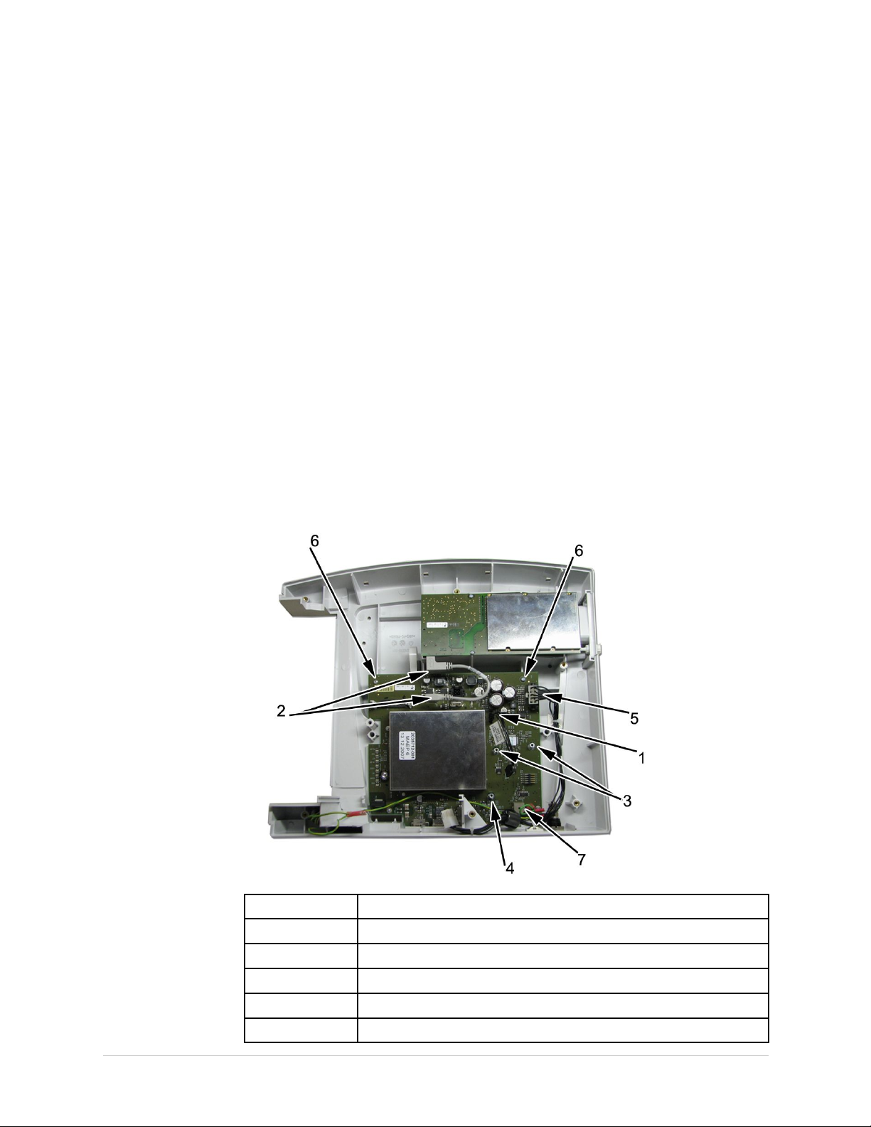
Maintenance
RemovingtheMainboard
Usethefollowingproceduretoremovethemainboard.
1.DisconnectthesystemfromACpower.
2.Removethepapertrayasdescribedin“ReplacingthePaperTrayAssembly”
onpage64.
3.Removethebatteryasdescribedin“ReplacingtheBattery”onpage64.
4.Removethedisplayasdescribedin“ReplacingtheDisplayAssembly”onpage
71.
5.Removethekeyboardasdescribedin“ReplacingtheKeyboard”onpage67.
6.Removetheinternalmodem(ifthisoptionisinstalled)asdescribedin“Replacing
theInternalModem(Option)”onpage71.
7.Removetherearconnectorpanel.
8.Separatethemiddleplasticandbaseplasticassemblies.
9.Removethepowersupplyasdescribedin“ReplacingthePowerSupply
Assembly”onpage72.
10.IftheKISSoptionisinstalled,removetheKISSpumpasdescribedin“Replacing
theKISSPumpAssembly(Option)”onpage77.
11.Disconnectandremovethefollowingfromthemainboard:
Item
1
2
3
4
5
96MAC™16002028451-183E
KISSpumpharnessconnector(ifthisoptionisinstalled).
BothendsofthegrayUSBcable.
ThetwoshorterKISSpumpstandoffs(ifthisoptionisinstalled).
ThelongerKISSpumpstandoff(ifthisoptionisinstalled).
Thepowersupplyconnector.
Description

Maintenance
Item
6
7
Thetwomountingscrews.
Thegroundinglugconnector.
Description
12.Pullthekeyboardribboncable(1)fromtheferriteloop(2).
13.Removethemainboard/ETEassembly.
14.Disconnectthekeyboardcablefromthebottomofthemainboard.
ReassemblingtheMainboard
Usethefollowingproceduretoreassemblethemainboard.
1.Reconnectthekeyboardcabletothebottomofthenewmainboard.
2.Insertthemainboardintothemainplastic.
3.Replacethetwobackmountingscrewsthatwereremovedinstep11of
“RemovingtheMainboard”onpage96.
4.Reconnectthethreecablesthatweredisconnectedinstep11of“Removing
theMainboard”onpage96.
5.IftheKISSoptionisinstalled,dothefollowing:
a.ReplacetheKISSpumpstandoff.
b.ReplacetheKISSpump.
c.RoutethetwotheKISSpumphosestothebackofthedeviceandconnect
themtotherearconnectorpanel.
6.Replacetherearconnectorpanel.
7.Reinsertthepowersupplyintheslottedguideswhilereconnectingthepower
supplyconnector.
8.ReconnectthelonggroundwiretotheACoutlet(pinkconnector).
9.Routethekeyboardcablebackthroughthekeyboardcablehole.
10.Iftheinternalmodemoptionisinstalled,replacetheinternalmodem.
2028451-183EMAC™160097

Maintenance
11.Reassemblethedisplay.
12.Replacethekeyboard.
13.Replacethekeyboardbezel.
14.Reattachthebaseplastic(1)tothemiddleplastic(2)bypushingtheACpower
connector(3)inasshowninthefollowingillustration.
15.Replacethe10screws.
16.Replacethebattery.
17.Replacethepapertray.
18.PowerupthesystemandinstallthesoftwarefromtheSDcardthatshipped
withthemainboard.Referto“UpdatingSoftware”onpage104forthedetailed
procedure.
19.RestoresystemsetupsthatweresavedtotheSDcardbeforethenew
mainboardwasinstalled.
a.InserttheSDcardwiththesavedsystemsetupsintotheSDcardslot.
b.OntheMainMenu,pressF5(SystemConguration).
c.PressF6(More)>F6(More)>F2(ImportSetup).
d.HighlightthesystemsetupleyouwanttoimportfromtheSDcard.
e.PressF1(Import).
f.Whenthefollowingmessageisdisplayed,pressF6(OK):Conguration
wassuccessfullyimported
g.RemovetheSDcardandstoreitinasecurelocation.
20.ConguretheDeviceSettings:
a.OntheMainMenu,pressF5(SystemConguration).
b.PressF6(More)>F6(More)>F5(ServiceSetup).
c.Whenprompted,entertheServicePassword.
Ifyoudonotknowthepassword,contactGEHealthcareTechnical
Support.
98MAC™16002028451-183E

d.SelectDeviceSettings.
e.IntheSerialNumbereld,typetheserialnumberofthedevice.
Referto“SerialNumberFormat”onpage14forinformationabout
theserialnumber.)
f.InthePrintheadResistanceeld,type1000.
g.SelecttheappropriatelanguagefromtheKeyboardlist.
Maintenance
h.PressF6(Save).
21.Reactivatethepurchasedoptions.
(Refertotheoperator’smanualforyoursystemforinstructionsonactivating
theoptions.)
22.Performtheapplicablecheckoutprocedures.
Referto“FunctionalCheckout”onpage99.
FunctionalCheckout
Thefollowingcheckoutproceduresapplytoyoursystem.
NOTE:
TheFRUcheckoutprocedureforanylistedFRUalsoappliestoitsinternalPCBs
andcomponents.
Ifthereisanasterisk(*)listedinthefollowingtables,performtheapplicable
componentorsystemcongurationprocedures.
FRUreplacementproceduresareinprevioussectionsofthischapterofthe
manual.
BasicSystemFRURepairs
FRUDescription
PatientCable
PrinterAssembly
Keyboard
DisplayModule
MainboardETEAssembly
2028451-183EMAC™160099
VisualInspectionFunctionalCheckoutProcedures
1,2,81,2,3
7,81,2,3,9
3,7,81,2,3,8
3,7,81,2,3,7
7,81,2,3,*4,*5,*6,*13

Maintenance
BasicSystemFRURepairs(cont'd.)
FRUDescription
AcquisitionAssembly
BatteryPack
PowerSupplyAssembly
SDCard
Plastics
ACPowerCord
Non-listedFRUs
OptionalSystemFRURepairs
FRUDescription
InternalModem
KISSPump7,81,2,3
ExternalModem
LANOption
BarcodeReader
VisualInspectionFunctionalCheckoutProcedures
1,2,7,81,2,3,*4,*5,*6,*13
5
7,81,2,3,15
61,2,3,4
7,8
4
7,8
VisualInspectionFunctionalCheckoutProcedures
7,81,2,3,5,14
81,2,3,5,14
81,2,3,5
7,81,2,3,6
1,2,3(*15–middleplasticonly)
1,2,3(*15–whenACpowermainsdisturbed)
1,2,3,12
1,2,3
Non-FRURepairs
Description
Nopartsreplaced
SoftwareUpdate
HardwareUpgrade
AnnualElectricalSafety
Checkout
VisualInspectionFunctionalCheckoutProcedures
4,5,7,81,2,3,*4,5,6
n/a
7,81,2,3,*4,5,6
1,3,4,51,2,3,7,8,9,10,11,12,15,*13,14
1,2,3,*4,5,6
VisualInspection
Inspectthefollowingforexcessivewearandanysignsofdamage.
1.Checkforbrokenpatientcable/leadwiresandout-of-dateelectrodes.
a.Verifythatpatientcable/leadwirespassinspection.
b.Verifythattheelectrodespassinspection.
2.Discusselectrodeplacement,skinprep,andpatient-relatedrequirementswith
theECGtechnician.
Verifythatthecustomerisfollowingtheproceduresrecommendedinthe
operator’smanual.
Formoreinformation,referto“PreparingthePatient”intheoperator’smanual
foryoursystem.
100MAC™16002028451-183E
 Loading...