

General Electric LOGIQ 7 SERVICE MANUAL_SM_2286865_14 BENCH FUME HOOD with Auto-return Sash LV05 Style Installation Instructions
Page 1

Technical
Publication
Direction 2286865
REVISION 14
GE Healthcare
GE Healthcare
LOGIQ™ 7 Service Manual
Copyright© 2001-2008
by General Electric Company Inc.
All Right Reserved
Page 2

Page 3

EALTHCARE
GE H
D
IRECTION 2286865, REVISION 14 LOGIQ™ 7 SERVICE MANUAL
Important Precautions
• THIS SERVICE MANUAL IS AVAILABLE IN ENGLISH ONLY.
• IF A CUSTOMER’S SERVICE PROVIDER REQUIRES A LANGUAGE OTHER THAN
ENGLISH, IT IS THE CUSTOMER’S RESPONSIBILITY TO PROVIDE
TRANSLATION SERVICES.
WARNING
AVERTISSEMENT
• DO NOT ATTEMPT TO SERVICE THE EQUIPMENT UNLESS THIS SERVICE
MANUAL HAS BEEN CONSULTED AND IS UNDERSTOOD.
• FAILURE TO HEED THIS WARNING MAY RESULT IN INJURY TO THE SERVICE
PROVIDER, OPERATOR OR PATIENT FROM ELECTRIC SHOCK, MECHANICAL
OR OTHER HAZARDS.
• CE MANUEL DE MAINTENANCE N’EST DISPONIBLE QU’EN ANGLAIS.
• SI LE PRESTATAIRE DE SERVICES DU CLIENT A BESOIN DE CE MANUEL DANS
UNE AUTRE LANGUE QUE L’ANGLAIS, IL INCOMBE AU CLIENT DE LE FAIRE
TRADUIRE.
• NE PAS TENTER D’INTERVENTION SUR LES é QUIPEMENTS TANT QUE LE
MANUEL DE MAINTENANCE N’A PAS éTé CONSULTé ET COMPRIS.
• LE NON-RESPECT DE CET AVERTISSEMENT PEUT ENTRAîNER CHEZ LE
TECHNICIEN, L’OPéRATEUR OU LE PATIENT DES BLESSURES DUES à DES
DANGERS éLECTRIQUES, Mé CANIQUES OU AUTRES.
WARNUNG
• DIESES KUNDENDIENST-HANDBUCH EXISTIERT NUR IN ENGLISCHER
SPRACHE.
• FALLS EIN FREMDER KUNDENDIENST EINE ANDERE SPRACHE BENö TIGT, IST
ES AUFGABE DES KUNDEN, FüR EINE ENTSPRECHENDE ÜBERSETZUNG ZU
SORGEN.
• WARTEN SIE DIESES GERÄT NUR, WENN SIE DIE ENTSPRECHENDEN
ANWEISUNGEN IM KUNDENDIENST-HANDBUCH GELESEN HABEN UND
NACHVOLLZIEHEN KÖNNEN.
• WIRD DIESE WARNUNG NICHT BEACHTET, SO KANN ES ZU VERLETZUNGEN
DES KUNDENDIENSTTECHNIKERS, DES BEDIENERS ODER DES PATIENTEN
DURCH ELEKTRISCHE SCHLä GE, MECHANISCHE ODER SONSTIGE
GEFAHREN KOMMEN.
- i
Page 4

GE HEALTHCARE
DIRECTION 2286865, REVISION 14 LOGIQ™ 7 SERVICE MANUAL
• ESTE MANUAL DE SERVICIO Só LO ESTÁ DISPONIBLE EN INGLéS.
• SI ALGúN PROVEEDOR DE SERVICIOS AJENO A GEMS SOLICITA UN IDIOMA
QUE NO SEA EL INGLéS, LA TRADUCCIÓN ES RESPONSABILIDAD DEL
CLIENTE.
• NO SE DEBERá DAR SERVICIO Té CNICO AL EQUIPO SIN HABER
AV I S O
CONSULTADO Y COMPRENDIDO ESTE MANUAL DE SERVICIO.
• LA NO OBSERVANCIA DEL PRESENTE AVISO PUEDE DAR LUGAR A QUE EL
PROVEEDOR DE SERVICIOS, EL USUARIO O EL PACIENTE SUFRAN LESIONES
PROVOCADAS POR DESCARGAS ELéCTRICAS, PROBLEMAS MECÁNICOS O
PELIGROS DE OTRA NATURALEZA.
• ESTE MANUAL DE ASSISTê NCIA TéCNICA Só SE ENCONTRA DISPONíVEL EM
INGLê S.
• SE QUALQUER OUTRO SERVIç O DE ASSISTê NCIA TéCNICA, QUE Nã O A
GEMS, SOLICITAR ESTES MANUAIS NOUTRO IDIOMA, é DA
RESPONSABILIDADE DO CLIENTE FORNECER OS SERVIç OS DE TRADUç ã O.
ATENÇÃO
• Nã O TENTE REPARAR O EQUIPAMENTO SEM TER CONSULTADO E
COMPREENDIDO ESTE MANUAL DE ASSISTêNCIA Té CNICA.
• O Nã O CUMPRIMENTO DESTE AVISO PODE PÔR EM PERIGO A SEGURANç A
DO TéCNICO, OPERADOR OU PACIENTE DEVIDO A CHOQUES ELéTRICOS,
MECâ NICOS OU OUTROS.
AVVERTENZA
HOIATUS
• IL PRESENTE MANUALE DI MANUTENZIONE è DISPONIBILE SOLTANTO IN
INGLESE.
• SE UN ADDETTO ALLA MANUTENZIONE ESTERNO ALLA GEMS RICHIEDE IL
MANUALE IN UNA LINGUA DIVERSA, IL CLIENTE è TENUTO A PROVVEDERE
DIRETTAMENTE ALLA TRADUZIONE.
• SI PROCEDA ALLA MANUTENZIONE DELL’APPARECCHIATURA SOLO DOPO
AVER CONSULTATO IL PRESENTE MANUALE ED AVERNE COMPRESO IL
CONTENUTO.
• NON TENERE CONTO DELLA PRESENTE AVVERTENZA POTREBBE FAR
COMPIERE OPERAZIONI DA CUI DERIVINO LESIONI ALL’ADDETTO ALLA
MANUTENZIONE, ALL’UTILIZZATORE ED AL PAZIENTE PER FOLGORAZIONE
ELETTRICA, PER URTI MECCANICI OD ALTRI RISCHI.
• KÄESOLEV TEENINDUSJUHEND ON SAADAVAL AINULT INGLISE KEELES.
• KUI KLIENDITEENINDUSE OSUTAJA Nõ UAB JUHENDIT INGLISE KEELEST
ERINEVAS KEELES, VASTUTAB KLIENT Tõ LKETEENUSE OSUTAMISE EEST.
• ä RGE ü RITAGE SEADMEID TEENINDADA ENNE EELNEVALT Kä ESOLEVA
TEENINDUSJUHENDIGA TUTVUMIST JA SELLEST ARU SAAMIST.
• Kä ESOLEVA HOIATUSE EIRAMINE Võ IB Põ HJUSTADA TEENUSEOSUTAJA,
OPERAATORI Võ I PATSIENDI VIGASTAMIST ELEKTRILö ö GI, MEHAANILISE
Võ I MUU OHU TAGAJä RJEL.
ii -
Page 5

EALTHCARE
GE H
D
IRECTION 2286865, REVISION 14 LOGIQ™ 7 SERVICE MANUAL
• TÄMÄ HUOLTO-OHJE ON SAATAVILLA VAIN ENGLANNIKSI.
• JOS ASIAKKAAN PALVELUNTARJOAJA VAATII MUUTA KUIN
ENGLANNINKIELISTä MATERIAALIA, TARVITTAVAN Kä ä NNö KSEN
HANKKIMINEN ON ASIAKKAAN VASTUULLA.
• ä Lä YRITä KORJATA LAITTEISTOA ENNEN KUIN OLET VARMASTI LUKENUT
VAROITUS
JA YMMä RTä NYT Tä Mä N HUOLTO-OHJEEN.
• MIKä LI Tä Tä VAROITUSTA EI NOUDATETA, SEURAUKSENA VOI OLLA
PALVELUNTARJOAJAN, LAITTEISTON Kä YTTä Jä N TAI POTILAAN
VAHINGOITTUMINEN Sä HKö ISKUN, MEKAANISEN VIAN TAI MUUN
VAARATILANTEEN VUOKSI.
• ΤΟ ΠΑΡΟΝ ΕΓΧΕΙΡΙ∆ΙΟ ΣΕΡΒΙΣ ∆ΙΑΤΙΘΕΤΑΙ ΣΤΑ ΑΓΓΛΙΚΑ ΜΟΝΟ.
• ΕΑΝ ΤΟ ΑΤΟΜΟ ΠΑΡΟΧΗΣ ΣΕΡΒΙΣ ΕΝΟΣ ΠΕΛΑΤΗ ΑΠΑΙΤΕΙ ΤΟ ΠΑΡΟΝ
ΕΓΧΕΙΡΙ∆ΙΟ ΣΕ ΓΛΩΣΣΑ ΕΚΤΟΣ ΤΩΝ ΑΓΓΛΙΚΩΝ, ΑΠΟΤΕΛΕΙ ΕΥΘΥΝΗ ΤΟΥ
ΠΕΛΑΤΗ ΝΑ ΠΑΡΕΧΕΙ ΥΠΗΡΕΣΙΕΣ ΜΕΤΑΦΡΑΣΗΣ.
• ΜΗΝ ΕΠΙΧΕΙΡΗΣΕΤΕ ΤΗΝ ΕΚΤΕΛΕΣΗ ΕΡΓΑΣΙΩΝ ΣΕΡΒΙΣ ΣΤΟΝ ΕΞΟΠΛΙΣΜΟ
ΠΡΟΕΙ∆ΟΠΟΙΗΣΗ
ΕΚΤΟΣ ΕΑΝ ΕΧΕΤΕ ΣΥΜΒΟΥΛΕΥΤΕΙ ΚΑΙ ΕΧΕΤΕ ΚΑΤΑΝΟΗΣΕΙ ΤΟ ΠΑΡΟΝ
ΕΓΧΕΙΡΙ∆ΙΟ ΣΕΡΒΙΣ.
• ΕΑΝ ∆Ε ΛΑΒΕΤΕ ΥΠΟΨΗ ΤΗΝ ΠΡΟΕΙ∆ΟΠΟΙΗΣΗ ΑΥΤΗ, ΕΝ∆ΕΧΕΤΑΙ ΝΑ
ΠΡΟΚΛΗΘΕΙ ΤΡΑΥΜΑΤΙΣΜΟΣ ΣΤΟ ΑΤΟΜΟ ΠΑΡΟΧΗΣ ΣΕΡΒΙΣ, ΣΤΟ ΧΕΙΡΙΣΤΗ Ή
ΣΤΟΝ ΑΣΘΕΝΗ ΑΠΟ ΗΛΕΚΤΡΟΠΛΗΞΙΑ, ΜΗΧΑΝΙΚΟΥΣ Ή ΑΛΛΟΥΣ ΚΙΝ∆ΥΝΟΥΣ.
FIGYELMEZTETÉS
VIÐVÖRUN
• EZEN KARBANTARTÁSI KÉZIKÖNYV KIZÁRÓLAG ANGOL NYELVEN ÉRHETŐ
EL.
• HA A VEVŐ SZOLGÁLTATÓJA ANGOLTÓL ELTÉRŐ NYELVRE TART IGÉNYT,
AKKOR A VEVŐ FELELŐSSÉGE A FORDÍTÁS ELKÉSZÍTTETÉSE.
• NE PRÓBÁLJA ELKEZDENI HASZNÁLNI A BERENDEZÉST, AMÍG A
KARBANTARTÁSI KÉZIKÖNYVBEN LEÍRTAKAT NEM ÉRTELMEZTÉK.
• EZEN FIGYELMEZTETÉS FIGYELMEN KÍVÜL HAGYÁSA A SZOLGÁLTATÓ,
MŰKÖDTETŐ VAGY A BETEG ÁRAMÜTÉS, MECHANIKAI VAGY EGYÉB
VESZÉLYHELYZET MIATTI SÉRÜLÉSÉT EREDMÉNYEZHETI.
• ÞESSI ÞJÓNUSTUHANDBÓK ER EINGÖNGU FÁANLEG Á ENSKU.
• EF ÞJÓNUSTUAÐILI VIÐSKIPTAMANNS ÞARFNAST ANNARS TUNGUMÁLS EN
ENSKU, ER ÞAÐ Á ÁBYRGÐ VIÐSKIPTAMANNS AÐ ÚTVEGA ÞÝÐINGU.
• REYNIÐ EKKI AÐ ÞJÓNUSTA TÆKIÐ NEMA EFTIR AÐ HAFA SKOÐAÐ OG SKILIÐ
ÞESSA ÞJÓNUSTUHANDBÓK.
• EF EKKI ER FARIÐ AÐ ÞESSARI VIÐVÖRUN GETUR ÞAÐ VALDIÐ MEIÐSLUM
ÞJÓNUSTUVEITANDA, STJÓRNANDA EÐA SJÚKLINGS VEGNA RAFLOSTS,
VÉLRÆNNAR EÐA ANNARRAR HÆTTU.
- iii
Page 6

GE HEALTHCARE
DIRECTION 2286865, REVISION 14 LOGIQ™ 7 SERVICE MANUAL
• TENTO SERVISNÍ NÁVOD EXISTUJE POUZE V ANGLICKé M JAZYCE.
• V Př íPADě, ŽE POSKYTOVATEL SLUŽEB ZÁKAZNÍKŮM POTř EBUJE Ná VOD V
JINéM JAZYCE, JE ZAJIšTěNí Př EKLADU DO ODPOVíDAJíCíHO JAZYKA
úKOLEM Zá KAZNíKA.
• NEPROVÁDĚJTE úDRŽBU TOHOTO ZAř íZENí, ANIŽ BYSTE SI Př Eč ETLI
VÝSTRAHA
TENTO SERVISNÍ NÁVOD A POCHOPILI JEHO OBSAH.
• V Př íPADě NEDODRŽOVá Ní TéTO VýSTRAHY Mů ŽE DOJíT ÚRAZU
ELEKTRICKÁM PROUDEM PRACOVNíKA POSKYTOVATELE SLUŽEB,
OBSLUŽNéHO PERSONá LU NEBO PACIENTů VLIVEM ELEKTRICKéHOP
PROUDU, RESPEKTIVE VLIVEM K RIZIKU MECHANICKÉHO POŠKOZENÍ NEBO
JINÉMU RIZIKU.
• DENNE SERVICEMANUAL FINDES KUN PÅ ENGELSK.
• HVIS EN KUNDES TEKNIKER HAR BRUG FOR ET ANDET SPROG END
ENGELSK, ER DET KUNDENS ANSVAR AT SØRGE FOR OVERSÆTTELSE.
• FORSØG IKKE AT SERVICERE UDSTYRET MEDMINDRE
ADVARSEL
DENNE SERVICEMANUAL ER BLEVET LÆST OG FORSTÅET.
• MANGLENDE OVERHOLDELSE AF DENNE ADVARSEL KAN MEDFØRE SKADE
PÅ GRUND AF ELEKTRISK, MEKANISK ELLER ANDEN FARE FOR TEKNIKEREN,
OPERATØREN ELLER PATIENTEN.
WAARSCHUWING
BRÎDINÂJUMS
• DEZE ONDERHOUDSHANDLEIDING IS ENKEL IN HET ENGELS
VERKRIJGBAAR.
• ALS HET ONDERHOUDSPERSONEEL EEN ANDERE TAAL VEREIST, DAN IS DE
KLANT VERANTWOORDELIJK VOOR DE VERTALING ERVAN.
• PROBEER DE APPARATUUR NIET TE ONDERHOUDEN VOORDAT DEZE
ONDERHOUDSHANDLEIDING WERD GERAADPLEEGD EN BEGREPEN IS.
• INDIEN DEZE WAARSCHUWING NIET WORDT OPGEVOLGD, ZOU HET
ONDERHOUDSPERSONEEL, DE OPERATOR OF EEN PATIËNT GEWOND
KUNNEN RAKEN ALS GEVOLG VAN EEN ELEKTRISCHE SCHOK,
MECHANISCHE OF ANDERE GEVAREN.
• ðÎ APKALPES ROKASGRÂMATA IR PIEEJAMA TIKAI ANGÏU VALODÂ.
• JA KLIENTA APKALPES SNIEDZÇJAM NEPIECIEÐAMA INFORMÂCIJA CITÂ
VALODÂ, NEVIS ANGÏU, KLIENTA PIENÂKUMS IR NODROÐINÂT TULKOÐANU.
• NEVEICIET APRÎKOJUMA APKALPI BEZ APKALPES ROKASGRÂMATAS
IZLASÎÐANAS UN SAPRAÐANAS.
• ÐÎ BRÎDINÂJUMA NEIEVÇROÐANA VAR RADÎT ELEKTRISKÂS STRÂVAS
TRIECIENA, MEHÂNISKU VAI CITU RISKU IZRAISÎTU TRAUMU APKALPES
SNIEDZÇJAM, OPERATORAM VAI PACIENTAM.
iv -
Page 7

EALTHCARE
GE H
D
IRECTION 2286865, REVISION 14 LOGIQ™ 7 SERVICE MANUAL
• ÐIS EKSPLOATAVIMO VADOVAS YRA IÐLEISTAS TIK ANGLØ KALBA.
• JEI KLIENTO PASLAUGØ TEIKËJUI REIKIA VADOVO KITA KALBA – NE
ANGLØ, VERTIMU PASIRÛPINTI TURI KLIENTAS.
• NEMËGINKITE ATLIKTI ÁRANGOS TECHNINËS PRIEÞIÛROS DARBØ, NEBENT
ÁSPËJIMAS
VADOVAUTUMËTËS ÐIUO EKSPLOATAVIMO VADOVU IR JÁ SUPRASTUMËTE
• NEPAISANT ÐIO PERSPËJIMO, PASLAUGØ TEIKËJAS, OPERATORIUS AR
PACIENTAS GALI BÛTI SUÞEISTAS DËL ELEKTROS SMÛGIO, MECHANINIØ AR
KITØ PAVOJØ.
• DENNE SERVICEHÅNDBOKEN FINNES BARE PÅ ENGELSK.
• HVIS KUNDENS SERVICELEVERANDØR TRENGER ET ANNET SPRÅK, ER DET
KUNDENS ANSVAR Å SØRGE FOR OVERSETTELSE.
• IKKE FORSØK Å REPARERE UTSTYRET UTEN AT DENNE
ADVARSEL
SERVICEHÅNDBOKEN ER LEST OG FORSTÅTT.
• MANGLENDE HENSYN TIL DENNE ADVARSELEN KAN FØRE TIL AT
SERVICELEVERANDØREN, OPERATØREN ELLER PASIENTEN SKADES PÅ
GRUNN AV ELEKTRISK STØT, MEKANISKE ELLER ANDRE FARER.
OSTRZEŻENIE
ATE NŢIE
• NINIEJSZY PODRĘCZNIK SERWISOWY DOSTĘPNY JEST JEDYNIE W JĘZYKU
ANGIELSKIM.
• JEśLI FIRMA śWIADCZĄCA KLIENTOWI USłUGI SERWISOWE WYMAGA
UDOSTęPNIENIA PODRę CZNIKA W JęZYKU INNYM NIŻ ANGIELSKI,
OBOWIĄZEK ZAPEWNIENIA STOSOWNEGO TłUMACZENIA SPOCZYWA NA
KLIENCIE.
• NIE PRó BOWAć SERWISOWAć NINIEJSZEGO SPRZęTU BEZ UPRZEDNIEGO
ZAPOZNANIA SIę Z PODRęCZNIKIEM SERWISOWYM.
• NIEZASTOSOWANIE SIę DO TEGO OSTRZEŻENIA MOżE GROZIć
OBRAŻENIAMI CIAłA SERWISANTA, OPERATORA LUB PACJENTA W WYNIKU
PORAŻENIA PRĄDEM, URAZU MECHANICZNEGO LUB INNEGO RODZAJU
ZAGROŻEń.
• ACEST MANUAL DE SERVICE ESTE DISPONIBIL NUMAI ÎN LIMBA ENGLEZĂ.
• DACĂ UN FURNIZOR DE SERVICII PENTRU CLIENŢI NECESITĂ O ALTĂ LIMBĂ
DECÂT CEA ENGLEZĂ, ESTE DE DATORIA CLIENTULUI SĂ FURNIZEZE O
TRADUCERE.
• NU ÎNCERCAŢI SĂ REPARAŢI ECHIPAMENTUL DECÂT ULTERIOR
CONSULTĂRII I ÎNŢELEGERII ACESTUI MANUAL DE SERVICE.
• IGNORAREA ACESTUI AVERTISMENT AR PUTEA DUCE LA RĂNIREA
DEPANATORULUI, OPERATORULUI SAU PACIENTULUI ÎN URMA
PERICOLELOR DE ELECTROCUTARE, MECANICE SAU DE ALTĂ NATURĂ.
- v
Page 8

GE HEALTHCARE
DIRECTION 2286865, REVISION 14 LOGIQ™ 7 SERVICE MANUAL
• Данное рук о во дс тв о по обслуживанию ПРЕДОСТАВЛЯЕТСЯ
только на английском Язы ке .
• Ес ли сервисноМУ ПЕРСОНАЛУ клиента необходимо рук о во дс тво
не на английском ЯЗЫКЕ, клиенту следует самостоЯтельно
ОБЕСПЕЧИТЬ перевод.
ОСТОРОЖНО!
• ПЕРЕД ОБСЛУЖИВАНИЕМ ОБОРУДОВАНИЯ ОБЯЗАТЕЛЬНО ОБРАТИТЕСЬ
К ДАННОМУ РУКОВОДСТВУ И ПОЙМИТЕ ИЗЛОЖЕННЫЕ В НЕМ СВЕДЕНИЯ.
• НЕСОБЛЮДЕНИЕ УКАЗАННЫХ ТРЕБОВАНИЙ МОЖЕТ ПРИВЕСТИ К ТОМУ,
ЧТО СПЕЦИАЛИСТ ПО ТЕХОБСЛУЖИВАНИЮ, ОПЕРАТОР ИЛИ ПАЦИЕНТ
ПОЛУЧАТ УДАР ЗЛЕКТРИЧЕСКИМ ТОКОМ, МЕХАНИЧЕСКУЮ ТРАВМУ ИЛИ
ДРУГОЕ ПОВРЕЖДЕНИЕ.
• TÁTO SERVISNÁ PRÍRUČKA JE K DISPOZíCII LEN V ANGLIČTINE.
• AK ZÁKAZNÍKOV POSKYTOVATEĽ SLUŽIEB VYŽADUJE INÝ JAZYK AKO
ANGLIČTINU, POSKYTNUTIE PREKLADATEĽSKÝCH SLUŽIEB JE
ZODPOVEDNOSŤOU ZÁKAZNÍKA.
• NEPOKÚŠAJTE SA VYKONÁVAŤ SERVIS ZARIADENIA SKÔR, AKO SI
UPOZORNENIE
NEPREČÍTATE SERVISNÚ PRÍRUČKU A NEPOROZUMIETE JEJ.
• ZANEDBANIE TOHTO UPOZORNENIA Mô ŽE VYÚSTIŤ DO ZRANENIA
POSKYTOVATEĽA SLUŽIEB, OBSLUHUJú CEJ OSOBY ALEBO PACIENTA
ELEKTRICKýM PRúDOM, PRÍPADNE DO MECHANICKéHO ALEBO INéHO
NEBEZPEč ENSTVA.
VARNING
DKKAT
• DEN HÄR SERVICEHANDBOKEN FINNS BARA TILLGÄNGLIG PÅ ENGELSKA.
• OM EN KUNDS SERVICETEKNIKER HAR BEHOV AV ETT ANNAT SPRÅK ÄN
ENGELSKA ANSVARAR KUNDEN FÖR ATT TILLHANDAHÅLLA
ÖVERSÄTTNINGSTJÄNSTER.
• FÖRSÖK INTE UTFÖRA SERVICE PÅ UTRUSTNINGEN OM DU INTE HAR LÄST
OCH FÖRSTÅR DEN HÄR SERVICEHANDBOKEN.
• OM DU INTE TAR HÄNSYN TILL DEN HÄR VARNINGEN KAN DET RESULTERA I
SKADOR PÅ SERVICETEKNIKERN, OPERATÖREN ELLER PATIENTEN TILL
FÖLJD AV ELEKTRISKA STÖTAR, MEKANISKA FAROR ELLER ANDRA FAROR.
• BU SERVS KILAVUZU YALNIZCA NGLZCE OLARAK SAĞLANMITIR.
• EĞER MÜTER TEKNSYEN KILAVUZUN NGLZCE DIINDAK BR DLDE
OLMASINI STERSE, KILAVUZU TERCÜME ETTRMEK MÜTERNN
SORUMLULUĞUNDADIR.
• SERVS KILAVUZUNU OKUYUP ANLAMADAN EKPMANLARA MÜDAHALE
ETMEYNZ.
• BU UYARININ GÖZ ARDI EDLMES, ELEKTRK ÇARPMASI YA DA MEKANK
VEYA DĞER TÜRDEN KAZALAR SONUCUNDA TEKNSYENN, OPERATÖRÜN
YA DA HASTANIN YARALANMASINA YOL AÇABLR.
vi -
Page 9

EALTHCARE
GE H
D
IRECTION 2286865, REVISION 14 LOGIQ™ 7 SERVICE MANUAL
- vii
Page 10

GE HEALTHCARE
DIRECTION 2286865, REVISION 14 LOGIQ™ 7 SERVICE MANUAL
DAMAGE IN TRANSPORTATION
All packages should be closely examined at time of delivery. If damage is apparent write “Damage In
Shipment” on ALL copies of the freight or express bill BEFORE delivery is accepted or “signed for” by
a GE representative or hospital receiving agent. Whether noted or concealed, damage MUST be
reported to the carrier immediately upon discovery, or in any event, within 14 days after receipt, and the
contents and containers held for inspection by the carrier. A transportation company will not pay a claim
for damage if an inspection is not requested within this 14 day period.
CERTIFIED ELECTRICAL CONTRACTOR STATEMENT
All electrical Installations that are preliminary to positioning of the equipment at the site prepared for the
equipment shall be performed by licensed electrical contractors. Other connections between pieces of
electrical equipment, calibrations and testing shall be performed by qualified GE Medical Systems
personnel. In performing all electrical work on these products, GE will use its own specially trained field
engineers. All of GE’s electrical work on these products will comply with the requirements of the
applicable electrical codes.
The purchaser of GE equipment shall only utilize qualified personnel (i.e., GE’s field engineers,
personnel of third-party service companies with equivalent training, or licensed electricians) to perform
electrical servicing on the equipment.
OMISSIONS & ERRORS
If there are any omissions, errors or suggestions for improving this documentation, please contact the
GE Medical Systems Global Documentation Group with specific information listing the system type,
manual title, part number, revision number, page number and suggestion details. Mail the information
to : Service Documentation,9900 Innovation Drive (RP-2123), Wauwatosa, WI 53226, USA.
GE Medical Systems employees should use the iTrak System to report all documentation errors or
omissions.
viii -
Page 11

EALTHCARE
GE H
D
IRECTION 2286865, REVISION 14 LOGIQ™ 7 SERVICE MANUAL
LEGAL NOTES
The contents of this publication may not be copied or duplicated in any form, in whole or in part, without
prior written permission of GE Medical Systems.
GE Medical Systems may revise this publication from time to time without written notice.
PROPRIETARY TO GE MEDICAL SYSTEMS
Permission to use this Advanced Service Software and related documentation (herein called the
material) by persons other than GE Medical Systems employees is provided only under an Advanced
Service Package License relating specifically to this Proprietary Material. This is a different agreement
from the one under which operating and basic service software is licensed. A license to use operating
or basic service software does not extend to or cover this software or related documentation.
If you are a GE Medical Systems employee or a customer who has entered into such a license
agreement with GE Medical Systems to use this proprietary software, you are authorized to use this
Material according to the conditions stated in your license agreement.
However, you do not have the permission of GE Medical Systems to alter, decompose or reverseassemble the software, and unless you are a GE employee, you may not copy the Material. The Material
is protected by Copyright and Trade Secret laws; the violation of which can result in civil damages and
criminal prosecution.
If you are not party to such a license agreement or a GE Medical Systems Employee, you must exit this
Material now.
TRADEMARKS
All products and their name brands are trademarks of their respective holders.
COPYRIGHTS
All Material Copyright© 2001-2008 by General Electric Inc. All Rights Reserved
- ix
Page 12

GE HEALTHCARE
DIRECTION 2286865, REVISION 14 LOGIQ™ 7 SERVICE MANUAL
x -
Page 13

GE HEALTHCARE
DIRECTION 2286865, REVISION 14 LOGIQ™ 7 SERVICE MANUAL
Revision History
Revision Date Reason for change
0 September 1, 2001 Initial Release
1 November 20, 2001 Revision 1
Electrical Requirements (sec2), STCW and TXCW theory, Monitor video
2 February 22, 2002
3 November 11, 2002
specification (sec5), TRAP2 Dip SW, QCON Dip SW, LV2 unit
released,Trackball cleaning (sec 6), New diagnostics (sec 7), New LFC
procedure added (sec8), New part number (sec9)
Probe precaution (sec1), Optional peripherals (sec3), Dongles (sec5),
Trackball cleaning, Jumper and Dip switch setting (sec6), Diagnostics
(sec7), PC box replacement, software loading for R2 (sec8), New part
number (sec9),
4 April 2, 2003
5 October 22, 2003
6 September 17, 2004 BT04
7 March 3, 2005 For L7Pro: Renewal Parts (sec9), Component Replacement (sec8)
8 September 30, 2005 BT06
9 June 26, 2006 BT06-2 released
10 September 22, 2006 Minor correction (sec 8), V65x (Sec1, Sec3, Sec5, Sec8, Sec9)
11 March 5, 2007 BT07 Supported
12 May 28, 2007 Setting Report Printer added (sec 8)
13 Oct.1, 2007 R7.5.x supported, other modifications (all sections)
14 July 16, 2008 BT09 newly released
Monitor and LCD Adjustment, DDBF and Trap settings (sec6), Keyboard
FRU replacement (sec8), Renewal Parts (sec9)
Added: New Printer and probe (Sec. 3), HDD Jumper setting (sec 6), New
PC box and DGVIC replacement, MOD setting, Service dongle notice at
Ghost, R3 software, DVD, TxCW connection notice (sec 8), New spare parts
(Sec. 9)
- xi
Page 14

GE HEALTHCARE
DIRECTION 2286865, REVISION 14 LOGIQ™ 7 SERVICE MANUAL
List of Effected Pages
PAGES REVISION PAGES REVISION PAGES REVISION
Title Page 14 1-1 to 1-23 14 Back Cover N/A
Warnings
i to v
Rev Hist/LOEP
vii to viii
Table of Contents
ix to xxiv
14 2-1 to 2-11 14
14 3-1 to 3-25 14
14 4-1 to 4-31 14
5-1 to 5-45 14
6-1 to 6-41 14
7-1 to 7-2 14
8-1 to 8-60 14
9-1 to 9-91 14
10-1 to 10-33 14
xii -
Page 15

GE HEALTHCARE
DIRECTION 2286865, REVISION 14 LOGIQ™ 7 SERVICE MANUAL
Table of Contents
CHAPTER 1
Introduction
Overview . . . . . . . . . . . . . . . . . . . . . . . . . . . . . . . . . . . . . . . . . . . . . . . . . . . . . . . . .1 - 1
Purpose of Chapter 1 . . . . . . . . . . . . . . . . . . . . . . . . . . . . . . . . . . . . . . . . . .1 - 1
Chapter Contents . . . . . . . . . . . . . . . . . . . . . . . . . . . . . . . . . . . . . . . . . . . . .1 - 1
Purpose of Service Manual . . . . . . . . . . . . . . . . . . . . . . . . . . . . . . . . . . . . .1 - 1
Typical Users of the Basic Service Manual . . . . . . . . . . . . . . . . . . . . . . . . .1 - 2
LOGIQ™ 7 Models Covered by this Manual . . . . . . . . . . . . . . . . . . . . . . . .1 - 2
Purpose of Operator Manual(s) . . . . . . . . . . . . . . . . . . . . . . . . . . . . . . . . . .1 - 4
Important Conventions. . . . . . . . . . . . . . . . . . . . . . . . . . . . . . . . . . . . . . . . . . . . . . .1 - 5
Conventions Used in Book . . . . . . . . . . . . . . . . . . . . . . . . . . . . . . . . . . . . . .1 - 5
Product Icons . . . . . . . . . . . . . . . . . . . . . . . . . . . . . . . . . . . . . . . . . . . . . . . .1 - 7
Introduction . . . . . . . . . . . . . . . . . . . . . . . . . . . . . . . . . . . . . . . . . . . . . . . . .1 - 10
Human Safety . . . . . . . . . . . . . . . . . . . . . . . . . . . . . . . . . . . . . . . . . . . . . . .1 - 10
Mechanical Safety . . . . . . . . . . . . . . . . . . . . . . . . . . . . . . . . . . . . . . . . . . . .1 - 10
Electrical Safety . . . . . . . . . . . . . . . . . . . . . . . . . . . . . . . . . . . . . . . . . . . . . .1 - 11
Label Locations (For BT07 or later, including R7.5.x) . . . . . . . . . . . . . . . . .1 - 12
Label Locations (For BT04, BT06, and V65x) . . . . . . . . . . . . . . . . . . . . . . .1 - 14
Lockout/Tagout Requirements (For USA Only) . . . . . . . . . . . . . . . . . . . . . .1 - 18
Returning/Shipping Probes and Repair Parts . . . . . . . . . . . . . . . . . . . . . . .1 - 18
How to remove the Ghost CD-ROM . . . . . . . . . . . . . . . . . . . . . . . . . . . . . . .1 - 19
Electromagnetic Compatibility . . . . . . . . . . . . . . . . . . . . . . . . . . . . . . . . . . .1 - 21
Electrostatic Discharge (ESD) Prevention . . . . . . . . . . . . . . . . . . . . . . . . . .1 - 21
CE Compliance . . . . . . . . . . . . . . . . . . . . . . . . . . . . . . . . . . . . . . . . . . . . . .1 - 21
Customer Assistance. . . . . . . . . . . . . . . . . . . . . . . . . . . . . . . . . . . . . . . . . . . . . . . .1 - 22
System Manufacture . . . . . . . . . . . . . . . . . . . . . . . . . . . . . . . . . . . . . . . . . .1 - 22
Contact Information . . . . . . . . . . . . . . . . . . . . . . . . . . . . . . . . . . . . . . . . . . .1 - 22
CHAPTER 2
Pre Installation
Overview . . . . . . . . . . . . . . . . . . . . . . . . . . . . . . . . . . . . . . . . . . . . . . . . . . . . . . . . .2 - 1
Purpose of this chapter 2 . . . . . . . . . . . . . . . . . . . . . . . . . . . . . . . . . . . . . . .2 - 1
Table of Contents xiii
Page 16

GE HEALTHCARE
DIRECTION 2286865, REVISION 14 LOGIQ™ 7 SERVICE MANUAL
General Console Requirements. . . . . . . . . . . . . . . . . . . . . . . . . . . . . . . . . . . . . . . .2 - 2
Console Environmental Requirements . . . . . . . . . . . . . . . . . . . . . . . . . . . . .2 - 2
Electrical Requirements . . . . . . . . . . . . . . . . . . . . . . . . . . . . . . . . . . . . . . . .2 - 3
EMI Limitations . . . . . . . . . . . . . . . . . . . . . . . . . . . . . . . . . . . . . . . . . . . . . .2 - 5
Probes Environmental Requirements . . . . . . . . . . . . . . . . . . . . . . . . . . . . .2 - 6
Facility Needs . . . . . . . . . . . . . . . . . . . . . . . . . . . . . . . . . . . . . . . . . . . . . . . . . . . . .2 - 7
Purchaser Responsibilities . . . . . . . . . . . . . . . . . . . . . . . . . . . . . . . . . . . . . .2 - 7
Required Features . . . . . . . . . . . . . . . . . . . . . . . . . . . . . . . . . . . . . . . . . . . .2 - 8
Desirable Ultrasound Room Facilities . . . . . . . . . . . . . . . . . . . . . . . . . . . . .2 - 8
Recommended and Alternate Ultrasound Room Layout . . . . . . . . . . . . . . .2 - 9
CHAPTER 3
Installation
Overview . . . . . . . . . . . . . . . . . . . . . . . . . . . . . . . . . . . . . . . . . . . . . . . . . . . . . . . . .3 - 1
Purpose of Chapter 3 . . . . . . . . . . . . . . . . . . . . . . . . . . . . . . . . . . . . . . . . . .3 - 1
Average Installation Time . . . . . . . . . . . . . . . . . . . . . . . . . . . . . . . . . . . . . . .3 - 1
Installation Warnings . . . . . . . . . . . . . . . . . . . . . . . . . . . . . . . . . . . . . . . . . .3 - 2
Safety Reminders . . . . . . . . . . . . . . . . . . . . . . . . . . . . . . . . . . . . . . . . . . . . .3 - 5
Moving into Position . . . . . . . . . . . . . . . . . . . . . . . . . . . . . . . . . . . . . . . . . . .3 - 6
LCD Monitor Tilt Caution . . . . . . . . . . . . . . . . . . . . . . . . . . . . . . . . . . . . . . .3 - 7
LCD Monitor Swing CautionLCD Monitor Tilt Caution . . . . . . . . . . . . . . . . .3 - 8
LCD Monitor Removal Caution . . . . . . . . . . . . . . . . . . . . . . . . . . . . . . . . . .3 - 9
Shipping Delivery Requirements . . . . . . . . . . . . . . . . . . . . . . . . . . . . . . . . .3 - 9
Preparing for Installation . . . . . . . . . . . . . . . . . . . . . . . . . . . . . . . . . . . . . . . . . . . . .3 - 10
Verify Customer Order . . . . . . . . . . . . . . . . . . . . . . . . . . . . . . . . . . . . . . . . .3 - 10
Physical Inspection . . . . . . . . . . . . . . . . . . . . . . . . . . . . . . . . . . . . . . . . . . .3 - 10
EMI Protection . . . . . . . . . . . . . . . . . . . . . . . . . . . . . . . . . . . . . . . . . . . . . . .3 - 10
Completing the Installation. . . . . . . . . . . . . . . . . . . . . . . . . . . . . . . . . . . . . . . . . . . .3 - 11
Probe (Transducer) Connection . . . . . . . . . . . . . . . . . . . . . . . . . . . . . . . . . .3 - 11
Optional Peripherals/Peripheral Connection . . . . . . . . . . . . . . . . . . . . . . . .3 - 12
Available Probes . . . . . . . . . . . . . . . . . . . . . . . . . . . . . . . . . . . . . . . . . . . . .3 - 15
Video Specification . . . . . . . . . . . . . . . . . . . . . . . . . . . . . . . . . . . . . . . . . . . .3 - 17
Software Option Configuration . . . . . . . . . . . . . . . . . . . . . . . . . . . . . . . . . . .3 - 17
Installation Paperwork . . . . . . . . . . . . . . . . . . . . . . . . . . . . . . . . . . . . . . . . . . . . . . .3 - 18
Peripherals/Accessories Connector Panel . . . . . . . . . . . . . . . . . . . . . . . . . .3 - 18
xiv -
Page 17

EALTHCARE
GE H
DIRECTION 2286865, REVISION 14 LOGIQ™ 7 SERVICE MANUAL
CHAPTER 4
Functional Checks
. . . . . . . . . . . . . . . . . . . . . . . . . . . . . . . . . . . . . . . . . . . . . . . . . . . . . . . . . . . . . . . .
Overview. . . . . . . . . . . . . . . . . . . . . . . . . . . . . . . . . . . . . . . . . . . . . . . . . . . . . . . . . 4 - 1
Purpose for Chapter 4 . . . . . . . . . . . . . . . . . . . . . . . . . . . . . . . . . . . . . . . . 4 - 1
Special Equipment Required . . . . . . . . . . . . . . . . . . . . . . . . . . . . . . . . . . . 4 - 1
General Procedure . . . . . . . . . . . . . . . . . . . . . . . . . . . . . . . . . . . . . . . . . . . . . . . . . 4 - 2
Lockout/Tagout Requirements . . . . . . . . . . . . . . . . . . . . . . . . . . . . . . . . . . 4 - 2
Power On/Boot Up . . . . . . . . . . . . . . . . . . . . . . . . . . . . . . . . . . . . . . . . . . . 4 - 2
Power Shutdown . . . . . . . . . . . . . . . . . . . . . . . . . . . . . . . . . . . . . . . . . . . . . 4 - 7
System Stand-by . . . . . . . . . . . . . . . . . . . . . . . . . . . . . . . . . . . . . . . . . . . . 4 - 7
Using CD-R/MOD/DVD Drive . . . . . . . . . . . . . . . . . . . . . . . . . . . . . . . . . . . 4 - 9
Archiving and Loading Presets for BT07 (Including R7.5.x) . . . . . . . . . . . . 4 - 11
Archiving and Loading Presets for BT06/V65x or lower . . . . . . . . . . . . . . . 4 - 16
Basic Controls . . . . . . . . . . . . . . . . . . . . . . . . . . . . . . . . . . . . . . . . . . . . . . . 4 - 20
Performance Tests . . . . . . . . . . . . . . . . . . . . . . . . . . . . . . . . . . . . . . . . . . . 4 - 20
Mode Checks . . . . . . . . . . . . . . . . . . . . . . . . . . . . . . . . . . . . . . . . . . . . . . . 4 - 21
Basic Measurements . . . . . . . . . . . . . . . . . . . . . . . . . . . . . . . . . . . . . . . . . 4 - 21
ECG Checks . . . . . . . . . . . . . . . . . . . . . . . . . . . . . . . . . . . . . . . . . . . . . . . . 4 - 22
Cineloop Check . . . . . . . . . . . . . . . . . . . . . . . . . . . . . . . . . . . . . . . . . . . . . 4 - 22
Backend Processor Checks . . . . . . . . . . . . . . . . . . . . . . . . . . . . . . . . . . . . 4 - 22
Probe/Connectors Usage (QG) . . . . . . . . . . . . . . . . . . . . . . . . . . . . . . . . . 4 - 22
Peripheral Checks . . . . . . . . . . . . . . . . . . . . . . . . . . . . . . . . . . . . . . . . . . . 4 - 23
Mechanical Functions . . . . . . . . . . . . . . . . . . . . . . . . . . . . . . . . . . . . . . . . . 4 - 24
Application Turnover Check List. . . . . . . . . . . . . . . . . . . . . . . . . . . . . . . . . . . . . . . 4 - 27
Software Configuration Checks . . . . . . . . . . . . . . . . . . . . . . . . . . . . . . . . . 4 - 27
Diagnostics . . . . . . . . . . . . . . . . . . . . . . . . . . . . . . . . . . . . . . . . . . . . . . . . . . . . . . . 4 - 28
Service Software Menu . . . . . . . . . . . . . . . . . . . . . . . . . . . . . . . . . . . . . . . . 4 - 28
Diagnostics Test Menu . . . . . . . . . . . . . . . . . . . . . . . . . . . . . . . . . . . . . . . . 4 - 28
Utility Menu . . . . . . . . . . . . . . . . . . . . . . . . . . . . . . . . . . . . . . . . . . . . . . . . . 4 - 28
Power Supply . . . . . . . . . . . . . . . . . . . . . . . . . . . . . . . . . . . . . . . . . . . . . . . . . . . . . 4 - 29
Power Supply Test Procedure . . . . . . . . . . . . . . . . . . . . . . . . . . . . . . . . . . 4 - 29
Power Supply Adjustment . . . . . . . . . . . . . . . . . . . . . . . . . . . . . . . . . . . . . . 4 - 29
Site Log . . . . . . . . . . . . . . . . . . . . . . . . . . . . . . . . . . . . . . . . . . . . . . . . . . . . . . . . . 4 - 30
- xv
Page 18

GE HEALTHCARE
DIRECTION 2286865, REVISION 14 LOGIQ™ 7 SERVICE MANUAL
CHAPTER 5
Components and Functions (Theory)
Overview . . . . . . . . . . . . . . . . . . . . . . . . . . . . . . . . . . . . . . . . . . . . . . . . . . . . . . . . .5 - 1
Hardware Compatibility Matrix. . . . . . . . . . . . . . . . . . . . . . . . . . . . . . . . . . . . . . . . .5 - 2
Hardware Compatibility BT09 or later . . . . . . . . . . . . . . . . . . . . . . . . . . . . .5 - 2
Hardware Identification Tip . . . . . . . . . . . . . . . . . . . . . . . . . . . . . . . . . . . . .5 - 8
Peripheral Compatibility . . . . . . . . . . . . . . . . . . . . . . . . . . . . . . . . . . . . . . . . . . . . . .5 - 11
Block Diagrams and Theory. . . . . . . . . . . . . . . . . . . . . . . . . . . . . . . . . . . . . . . . . . .5 - 12
Block Diagram (R7.5.x or later, 19 inch LCD model) . . . . . . . . . . . . . . . . . .5 - 12
General Information . . . . . . . . . . . . . . . . . . . . . . . . . . . . . . . . . . . . . . . . . . .5 - 13
CPU/Back End Processor (For BEP4 for BT09 or later) . . . . . . . . . . . . . . .5 - 14
CPU/Back End Processor (For BT06-2 or later) . . . . . . . . . . . . . . . . . . . . .5 - 21
Patient I/O (Option) . . . . . . . . . . . . . . . . . . . . . . . . . . . . . . . . . . . . . . . . . . .5 - 23
External I/O (Rear Panel) . . . . . . . . . . . . . . . . . . . . . . . . . . . . . . . . . . . . . . .5 - 23
Peripherals . . . . . . . . . . . . . . . . . . . . . . . . . . . . . . . . . . . . . . . . . . . . . . . . . .5 - 23
Interconnect Cabling (BT09 or later) . . . . . . . . . . . . . . . . . . . . . . . . . . . . . .5 - 24
Difference points between BT07 (or later) and BT06 (or earlier) Systems for R7.5.x 17"
to 19" LCD Monitor Upgrade . . . . . . . . . . . . . . . . . . . . . . . . . . . . . . . . . . . . . . . . . . . . . . .5 - 26
Common Service Platform. . . . . . . . . . . . . . . . . . . . . . . . . . . . . . . . . . . . . . . . . . . .5 - 27
Introduction . . . . . . . . . . . . . . . . . . . . . . . . . . . . . . . . . . . . . . . . . . . . . . . . .5 - 27
Calibration . . . . . . . . . . . . . . . . . . . . . . . . . . . . . . . . . . . . . . . . . . . . . . . . . .5 - 36
Configuration . . . . . . . . . . . . . . . . . . . . . . . . . . . . . . . . . . . . . . . . . . . . . . . .5 - 36
Replacement . . . . . . . . . . . . . . . . . . . . . . . . . . . . . . . . . . . . . . . . . . . . . . . .5 - 37
Remote Software/Option Installation and Updates . . . . . . . . . . . . . . . . . . .5 - 38
InSite II Configuration . . . . . . . . . . . . . . . . . . . . . . . . . . . . . . . . . . . . . . . . . .5 - 39
Password . . . . . . . . . . . . . . . . . . . . . . . . . . . . . . . . . . . . . . . . . . . . . . . . . . . . . . . . .5 - 40
For Operator Login Window . . . . . . . . . . . . . . . . . . . . . . . . . . . . . . . . . . . . .5 - 40
For Service Login Window . . . . . . . . . . . . . . . . . . . . . . . . . . . . . . . . . . . . . .5 - 40
For Maintenance Access Window . . . . . . . . . . . . . . . . . . . . . . . . . . . . . . . .5 - 41
Air Flow Control . . . . . . . . . . . . . . . . . . . . . . . . . . . . . . . . . . . . . . . . . . . . . . . . . . . .5 - 42
Air Flow Distribution . . . . . . . . . . . . . . . . . . . . . . . . . . . . . . . . . . . . . . . . . . .5 - 42
Filters . . . . . . . . . . . . . . . . . . . . . . . . . . . . . . . . . . . . . . . . . . . . . . . . . . . . . .5 - 42
Fans . . . . . . . . . . . . . . . . . . . . . . . . . . . . . . . . . . . . . . . . . . . . . . . . . . . . . . .5 - 43
Monitor Video Specification . . . . . . . . . . . . . . . . . . . . . . . . . . . . . . . . . . . . . . . . . . .5 - 44
Input . . . . . . . . . . . . . . . . . . . . . . . . . . . . . . . . . . . . . . . . . . . . . . . . . . . . . . .5 - 44
xvi -
Page 19

EALTHCARE
GE H
DIRECTION 2286865, REVISION 14 LOGIQ™ 7 SERVICE MANUAL
Outputs . . . . . . . . . . . . . . . . . . . . . . . . . . . . . . . . . . . . . . . . . . . . . . . . . . . . 5 - 44
SVHS and Composite Video . . . . . . . . . . . . . . . . . . . . . . . . . . . . . . . . . . . . 5 - 45
CHAPTER 6
Service Adjustments
Overview. . . . . . . . . . . . . . . . . . . . . . . . . . . . . . . . . . . . . . . . . . . . . . . . . . . . . . . . . 6 - 1
Purpose of this chapter 6 . . . . . . . . . . . . . . . . . . . . . . . . . . . . . . . . . . . . . . 6 - 1
LV Unit Adjustments (For BT03 or lower) . . . . . . . . . . . . . . . . . . . . . . . . . . . . . . . . 6 - 2
Access to Adjustments . . . . . . . . . . . . . . . . . . . . . . . . . . . . . . . . . . . . . . . . 6 - 2
Adjustments Procedures . . . . . . . . . . . . . . . . . . . . . . . . . . . . . . . . . . . . . . . 6 - 3
Caster Brake/Swivel Function Adjustments . . . . . . . . . . . . . . . . . . . . . . . . . . . . . . 6 - 4
Brake Function Adjustment . . . . . . . . . . . . . . . . . . . . . . . . . . . . . . . . . . . . . 6 - 4
Swivel Function Adjustment . . . . . . . . . . . . . . . . . . . . . . . . . . . . . . . . . . . . 6 - 8
Reloading the Probe Data . . . . . . . . . . . . . . . . . . . . . . . . . . . . . . . . . . . . . . . . . . . 6 - 9
Monitor and LCD Adjustments . . . . . . . . . . . . . . . . . . . . . . . . . . . . . . . . . . . . . . . . 6 - 10
CRT Monitor Contrast and Brightness Adjustment . . . . . . . . . . . . . . . . . . . 6 - 10
19 inch LCD Monitor Brightness Adjustment . . . . . . . . . . . . . . . . . . . . . . . 6 - 12
17 inch LCD Monitor Contrast and Brightness Adjustment . . . . . . . . . . . . 6 - 13
LCD Monitor Resolution . . . . . . . . . . . . . . . . . . . . . . . . . . . . . . . . . . . . . . . 6 - 14
LCD Touch Panel Adjustment . . . . . . . . . . . . . . . . . . . . . . . . . . . . . . . . . . 6 - 14
BW Printer Setting / Adjustment . . . . . . . . . . . . . . . . . . . . . . . . . . . . . . . . . . . . . . . 6 - 27
Parameters for UP-D897 . . . . . . . . . . . . . . . . . . . . . . . . . . . . . . . . . . . . . . 6 - 27
Parameters for UP-D895 . . . . . . . . . . . . . . . . . . . . . . . . . . . . . . . . . . . . . . 6 - 29
Service Tips - Print Quality . . . . . . . . . . . . . . . . . . . . . . . . . . . . . . . . . . . . . 6 - 30
Service Tips - Print Speed . . . . . . . . . . . . . . . . . . . . . . . . . . . . . . . . . . . . . 6 - 31
Cleaning the Trackball . . . . . . . . . . . . . . . . . . . . . . . . . . . . . . . . . . . . . . . . . . . . . . 6 - 33
Jumper and Dip Switch Setting . . . . . . . . . . . . . . . . . . . . . . . . . . . . . . . . . . . . . . . 6 - 37
Dip Switch Setting . . . . . . . . . . . . . . . . . . . . . . . . . . . . . . . . . . . . . . . . . . . . 6 - 37
Jumper Setting . . . . . . . . . . . . . . . . . . . . . . . . . . . . . . . . . . . . . . . . . . . . . . 6 - 39
Printer Dip Switch Setting . . . . . . . . . . . . . . . . . . . . . . . . . . . . . . . . . . . . . . 6 - 39
- xvii
Page 20

GE HEALTHCARE
DIRECTION 2286865, REVISION 14 LOGIQ™ 7 SERVICE MANUAL
CHAPTER 7
Diagnostics/Troubleshooting
Overview . . . . . . . . . . . . . . . . . . . . . . . . . . . . . . . . . . . . . . . . . . . . . . . . . . . . . . . . .7 - 1
Purpose of Chapter 7 . . . . . . . . . . . . . . . . . . . . . . . . . . . . . . . . . . . . . . . . . .7 - 1
Diagnostic Procedure Summary . . . . . . . . . . . . . . . . . . . . . . . . . . . . . . . . .7 - 2
CHAPTER 8
Replacement Procedures
Overview . . . . . . . . . . . . . . . . . . . . . . . . . . . . . . . . . . . . . . . . . . . . . . . . . . . . . . . . .8 - 1
Purpose of Chapter 8 . . . . . . . . . . . . . . . . . . . . . . . . . . . . . . . . . . . . . . . . . .8 - 1
Returning/Shipping Probes and Repair Parts . . . . . . . . . . . . . . . . . . . . . . .8 - 1
Software Loading Procedures for BT09 (R8.x.x or later). . . . . . . . . . . . . . . . . . . . .8 - 3
CHAPTER 9
Renewal Parts
Overview . . . . . . . . . . . . . . . . . . . . . . . . . . . . . . . . . . . . . . . . . . . . . . . . . . . . . . . . .9 - 1
Purpose of Chapter 9 . . . . . . . . . . . . . . . . . . . . . . . . . . . . . . . . . . . . . . . . . .9 - 1
List of Abbreviations. . . . . . . . . . . . . . . . . . . . . . . . . . . . . . . . . . . . . . . . . . . . . . . . .9 - 1
Renewal Parts List For BT09. . . . . . . . . . . . . . . . . . . . . . . . . . . . . . . . . . . . . . . . . .9 - 2
BT09, 19inch LCD: Equipment Models Covered in this Chapter (LOGIQ 7) 9 - 2
BT09 Parts . . . . . . . . . . . . . . . . . . . . . . . . . . . . . . . . . . . . . . . . . . . . . . . . . .9 - 3
Renewal Parts List For R7.5.x . . . . . . . . . . . . . . . . . . . . . . . . . . . . . . . . . . . . . . . . .9 - 5
R7.5.x, 19inch LCD: Equipment Models Covered in this Chapter (LOGIQ 7) 9 - 5
R7.5.x Parts . . . . . . . . . . . . . . . . . . . . . . . . . . . . . . . . . . . . . . . . . . . . . . . . .9 - 6
Renewal Parts List For BT07. . . . . . . . . . . . . . . . . . . . . . . . . . . . . . . . . . . . . . . . . .9 - 8
BT07, CRT: Equipment Models Covered in this Chapter (LOGIQ 7) . . . . . .9 - 8
BT07, LCD: Equipment Models Covered in this Chapter (LOGIQ 7) . . . . . .9 - 9
BT07 PRO: Equipment Models Covered in this Chapter (LOGIQ 7 PRO) . .9 - 10
BT07 Parts . . . . . . . . . . . . . . . . . . . . . . . . . . . . . . . . . . . . . . . . . . . . . . . . . .9 - 11
Renewal Parts List For V65x . . . . . . . . . . . . . . . . . . . . . . . . . . . . . . . . . . . . . . . . . .9 - 13
xviii -
Page 21

EALTHCARE
GE H
DIRECTION 2286865, REVISION 14 LOGIQ™ 7 SERVICE MANUAL
V65x, CRT: Equipment Models Covered in this Chapter (LOGIQ 7) . . . . . 9 - 13
V65x, LCD: Equipment Models Covered in this Chapter (LOGIQ 7) . . . . . 9 - 14
V65x PRO: Equipment Models Covered in this Chapter (LOGIQ 7 PRO) . 9 - 15
V65x Parts . . . . . . . . . . . . . . . . . . . . . . . . . . . . . . . . . . . . . . . . . . . . . . . . . 9 - 16
Renewal Parts List For BT06-2 or later . . . . . . . . . . . . . . . . . . . . . . . . . . . . . . . . . 9 - 17
BT06-2, CRT: Equipment Models Covered in this Chapter (LOGIQ 7) . . . 9 - 17
BT06-2, LCD: Equipment Models Covered in this Chapter (LOGIQ 7) . . . 9 - 18
BT06-2 PRO: Equipment Models Covered in this Chapter (LOGIQ 7 PRO) 9 - 19
BT06-2 Parts . . . . . . . . . . . . . . . . . . . . . . . . . . . . . . . . . . . . . . . . . . . . . . . . 9 - 20
Renewal Parts List For BT06-2 CONSIP (SOI) . . . . . . . . . . . . . . . . . . . . . . . . . . . 9 - 23
BT06-2 CONSIP: Equipment Models Covered in this Chapter (LOGIQ 7) . 9 - 23
BT06-2 CONSIP Parts . . . . . . . . . . . . . . . . . . . . . . . . . . . . . . . . . . . . . . . . 9 - 24
Renewal Parts List For BT04 and BT06. . . . . . . . . . . . . . . . . . . . . . . . . . . . . . . . . 9 - 25
BT06, CRT: Equipment Models Covered in this Chapter (LOGIQ 7) . . . . . 9 - 25
BT06, LCD: Equipment Models Covered in this Chapter (LOGIQ 7) . . . . . 9 - 26
BT06: Equipment Models Covered in this Chapter (LOGIQ 7 PRO) . . . . . 9 - 27
BT04: Equipment Models Covered in this Chapter (LOGIQ 7) . . . . . . . . . . 9 - 28
BT04: Equipment Models Covered in this Chapter (LOGIQ 7 PRO) . . . . . 9 - 29
Monitor . . . . . . . . . . . . . . . . . . . . . . . . . . . . . . . . . . . . . . . . . . . . . . . . . . . . 9 - 30
Casters and Pedals . . . . . . . . . . . . . . . . . . . . . . . . . . . . . . . . . . . . . . . . . . 9 - 32
Plastic Covers . . . . . . . . . . . . . . . . . . . . . . . . . . . . . . . . . . . . . . . . . . . . . . . 9 - 34
Recording Devices . . . . . . . . . . . . . . . . . . . . . . . . . . . . . . . . . . . . . . . . . . . 9 - 36
Probe Holder . . . . . . . . . . . . . . . . . . . . . . . . . . . . . . . . . . . . . . . . . . . . . . . . 9 - 37
OP Panel and Keys . . . . . . . . . . . . . . . . . . . . . . . . . . . . . . . . . . . . . . . . . . 9 - 38
Circuit Board Assemblies . . . . . . . . . . . . . . . . . . . . . . . . . . . . . . . . . . . . . . 9 - 40
HDD and Battery . . . . . . . . . . . . . . . . . . . . . . . . . . . . . . . . . . . . . . . . . . . . . 9 - 42
Power Units . . . . . . . . . . . . . . . . . . . . . . . . . . . . . . . . . . . . . . . . . . . . . . . . 9 - 44
Options, Peripherals and Cables . . . . . . . . . . . . . . . . . . . . . . . . . . . . . . . . 9 - 47
Probes . . . . . . . . . . . . . . . . . . . . . . . . . . . . . . . . . . . . . . . . . . . . . . . . . . . . 9 - 52
LCD Option . . . . . . . . . . . . . . . . . . . . . . . . . . . . . . . . . . . . . . . . . . . . . . . . . 9 - 54
Renewal Parts List for BT03 or lower . . . . . . . . . . . . . . . . . . . . . . . . . . . . . . . . . . . 9 - 57
Equipment Models Covered in this Chapter . . . . . . . . . . . . . . . . . . . . . . . . 9 - 57
Monitor . . . . . . . . . . . . . . . . . . . . . . . . . . . . . . . . . . . . . . . . . . . . . . . . . . . . 9 - 60
Casters and Pedals . . . . . . . . . . . . . . . . . . . . . . . . . . . . . . . . . . . . . . . . . . 9 - 62
Plastic Covers . . . . . . . . . . . . . . . . . . . . . . . . . . . . . . . . . . . . . . . . . . . . . . . 9 - 65
Recording Devices . . . . . . . . . . . . . . . . . . . . . . . . . . . . . . . . . . . . . . . . . . . 9 - 67
Probe Holder . . . . . . . . . . . . . . . . . . . . . . . . . . . . . . . . . . . . . . . . . . . . . . . . 9 - 69
OP Panel and Keys . . . . . . . . . . . . . . . . . . . . . . . . . . . . . . . . . . . . . . . . . . 9 - 70
Circuit Board Assemblies . . . . . . . . . . . . . . . . . . . . . . . . . . . . . . . . . . . . . . 9 - 73
- xix
Page 22

GE HEALTHCARE
DIRECTION 2286865, REVISION 14 LOGIQ™ 7 SERVICE MANUAL
HDD and Battery . . . . . . . . . . . . . . . . . . . . . . . . . . . . . . . . . . . . . . . . . . . . .9 - 75
Power Units . . . . . . . . . . . . . . . . . . . . . . . . . . . . . . . . . . . . . . . . . . . . . . . . .9 - 78
Options, Peripherals and Cables . . . . . . . . . . . . . . . . . . . . . . . . . . . . . . . . .9 - 80
Probes . . . . . . . . . . . . . . . . . . . . . . . . . . . . . . . . . . . . . . . . . . . . . . . . . . . . .9 - 90
CHAPTER 10
Periodic Maintenance
Overview . . . . . . . . . . . . . . . . . . . . . . . . . . . . . . . . . . . . . . . . . . . . . . . . . . . . . . . . .10 - 1
Purpose of Chapter 10 . . . . . . . . . . . . . . . . . . . . . . . . . . . . . . . . . . . . . . . . .10 - 1
Why do Periodic Maintenance . . . . . . . . . . . . . . . . . . . . . . . . . . . . . . . . . . . . . . . . .10 - 2
Keeping Records . . . . . . . . . . . . . . . . . . . . . . . . . . . . . . . . . . . . . . . . . . . . .10 - 2
Quality Assurance . . . . . . . . . . . . . . . . . . . . . . . . . . . . . . . . . . . . . . . . . . . .10 - 2
Periodic Maintenance Schedule . . . . . . . . . . . . . . . . . . . . . . . . . . . . . . . . . . . . . . .10 - 2
How often should PMs be performed? . . . . . . . . . . . . . . . . . . . . . . . . . . . . .10 - 2
Standard GE Tool Kit . . . . . . . . . . . . . . . . . . . . . . . . . . . . . . . . . . . . . . . . . .10 - 4
Special Tools, Supplies and Equipment . . . . . . . . . . . . . . . . . . . . . . . . . . . .10 - 6
Preliminary Checks . . . . . . . . . . . . . . . . . . . . . . . . . . . . . . . . . . . . . . . . . . .10 - 7
Input Power . . . . . . . . . . . . . . . . . . . . . . . . . . . . . . . . . . . . . . . . . . . . . . . . .10 - 9
Cleaning . . . . . . . . . . . . . . . . . . . . . . . . . . . . . . . . . . . . . . . . . . . . . . . . . . . .10 - 9
Physical Inspection . . . . . . . . . . . . . . . . . . . . . . . . . . . . . . . . . . . . . . . . . . .10 - 10
Probe Maintenance . . . . . . . . . . . . . . . . . . . . . . . . . . . . . . . . . . . . . . . . . . .10 - 11
Using a Phantom . . . . . . . . . . . . . . . . . . . . . . . . . . . . . . . . . . . . . . . . . . . . . . . . . . .10 - 11
Electrical Safety Tests . . . . . . . . . . . . . . . . . . . . . . . . . . . . . . . . . . . . . . . . . . . . . . .10 - 12
Safety Test Overview . . . . . . . . . . . . . . . . . . . . . . . . . . . . . . . . . . . . . . . . . .10 - 12
Grounding Continuity . . . . . . . . . . . . . . . . . . . . . . . . . . . . . . . . . . . . . . . . .10 - 15
Isolated Patient Lead (Source) Leakage–Lead to Ground . . . . . . . . . . . . . .10 - 19
Isolated Patient Lead (Source) Leakage–Lead to Lead . . . . . . . . . . . . . . . .10 - 22
Isolated Patient Lead (Sink) Leakage-Isolation Test . . . . . . . . . . . . . . . . . .10 - 22
Probe Leakage Current Test . . . . . . . . . . . . . . . . . . . . . . . . . . . . . . . . . . . .10 - 24
xx -
Page 23

GE HEALTHCARE
DIRECTION 2286865, REVISION 14 LOGIQ™ 7 SERVICE MANUAL
Chapter 1
Introduction
Section 1-1 Overview
1-1-1 Purpose of Chapter 1
This Chapter describes important issues related to safety servicing this ultrasound machine. The
service provider must read and understand all the information presented here before installing or
servicing a unit.
1-1-2 Chapter Contents
Table 1-1 Contents in Chapter 1
Section Description Page Number
1-1
1-2
1-3
1-4
1-5
Overview
Important Conventions
Safety Considerations
EMC, EMI, and ESD
Customer Assistance
1-1-3 Purpose of Service Manual
This manual provides service information on the LOGIQ™ 7 Ultrasound Scanning System. It contains
the following chapters:
1.) Chapter 1, Introduction: Contains a content summary and warnings.
2.) Chapter 2, Pre-Installation: Contains any pre-installation requirements for the LOGIQ™ 7.
3.) Chapter 3, Installation: Contains the LOGIQ™ 7 installation procedure with installation
checklist.
4.) Chapter 4, Functional Checks: Contains functional checks that must be performed as part of
the installation, or as required during servicing and periodic maintenance.
5.) Chapter 5 Theory: Contains block diagrams and functional explanations of the LOGIQ™ 7
electronics.
6.) Chapter 6, Service Adjustments: Contains instructions on how to make any available
adjustments to the LOGIQ™ 7.
7.) Chapter 7, Diagnostics/Trouble Shooting: Provides procedures for running and diagnostic
or related routines for the LOGIQ™ 7.
8.) Chapter 8, Replacement Procedures: Provides disassembly procedures and reassembly
procedures for all changeable FRU.
9.) Chapter 9, Renewal Parts: Contains a complete list of replacement parts for the LOGIQ™ 7.
10.)Chapter 10, Periodic Maintenance: Provides periodic maintenance procedures for the
LOGIQ™ 7.
1-1
1-5
1-10
1-21
1-22
Section 1-1 - Overview 1-1
Page 24

GE HEALTHCARE
DIRECTION 2286865, REVISION 14 LOGIQ™ 7 SERVICE MANUAL
1-1-4 Typical Users of the Basic Service Manual
• Service Personnel (installation, maintenance, etc.).
• Hospital’s Service Personnel
• Architects (Some parts of Chapter 2 - Pre-Installation)
1-1-5 LOGIQ™ 7 Models Covered by this Manual
Table 1-2 LOGIQ™ 7 Model Designations
Part Number Description Reference Remarks
2287317 LOGIQ™ 7 100V / NTSC Console and Peripherals BT01
2304806 LOGIQ™ 7 120V / NTSC Console and Peripherals BT01
2304807 LOGIQ™ 7 220V / PAL Console and Peripherals BT01
2304808 LOGIQ™ 7 220V / NTSC Console and Peripherals BT01
2354857 LOGIQ™ 7 100V / NTSC Console and Peripherals (Style B/Ver2) BT02
2354858 LOGIQ™ 7 120V / NTSC Console and Peripherals (Style B/Ver2) BT02
2354859 LOGIQ™ 7 220V / PAL Console and Peripherals (Style B/Ver2) BT02
2354860 LOGIQ™ 7 220V / NTSC Console and Peripherals (Style B/Ver2) BT02
2355589 LOGIQ™ 7 100V / NTSC Console and Peripherals (Style B/Ver2) BT02
2389221 LOGIQ™ 7 100V / NTSC Console and Peripherals (Style C/Ver3) BT03
2389220 LOGIQ™ 7 120V / NTSC Console and Peripherals (Style C/Ver3) BT03
2389219 LOGIQ™ 7 220V / PAL Console and Peripherals (Style C/Ver3) BT03
2389218 LOGIQ™ 7 220V / NTSC Console and Peripherals (Style C/Ver3) BT03
2389217 LOGIQ™ 7 100V / NTSC Console and Peripherals (Style C/Ver3) BT03
5118055 LOGIQ™ 7 100V / NTSC Console and Peripherals (Style D/Ver4) BT04
5118056 LOGIQ™ 7 120V / NTSC Console and Peripherals (Style D/Ver4) BT04
5118057 LOGIQ™ 7 220V / PAL Console and Peripherals (Style D/Ver4) BT04
5118058 LOGIQ™ 7 220V / NTSC Console and Peripherals (Style D/Ver4) BT04
5118059 LOGIQ™ 7 100V / NTSC Console and Peripherals (Style D/Ver4) BT04
5148047 LOGIQ™ 7 100V / NTSC Console and Peripherals, CRT monitor (Style E) BT06 CRT
5148048 LOGIQ™ 7 120V / NTSC Console and Peripherals, CRT monitor (Style E) BT06 CRT
5148049 LOGIQ™ 7 220V / PAL Console and Peripherals, CRT monitor (Style E) BT06 CRT
5148050 LOGIQ™ 7 220V / NTSC Console and Peripherals, CRT monitor (Style E) BT06 CRT
5148052 LOGIQ™ 7 100V / NTSC Console and Peripherals, LCD monitor (Style E) BT06 LCD
5148053 LOGIQ™ 7 120V / NTSC Console and Peripherals, LCD monitor (Style E) BT06 LCD
5148054 LOGIQ™ 7 220V / PAL Console and Peripherals, LCD monitor (Style E) BT06 LCD
5148055 LOGIQ™ 7 220V / NTSC Console and Peripherals, LCD monitor (Style E) BT06 LCD
5148057 LOGIQ™ 7PRO 100V / NTSC Console and Peripherals (Style E) BT06 PRO
1-2 Section 1-1 - Overview
Page 25

GE HEALTHCARE
DIRECTION 2286865, REVISION 14 LOGIQ™ 7 SERVICE MANUAL
Table 1-2 LOGIQ™ 7 Model Designations
Part Number Description Reference Remarks
5148058 LOGIQ™ 7PRO 120V / NTSC Console and Peripherals (Style E) BT06 PRO
5148059 LOGIQ™ 7PRO 220V / PAL Console and Peripherals (Style E) BT06 PRO
5148060 LOGIQ™ 7 220V / NTSC Console and Peripherals (Style E) BT06 PRO
5176232 LOGIQ™ 7 100V / NTSC Console and Peripherals, CRT monitor BT06-2 CRT
5176567 LOGIQ™ 7 120V / NTSC Console and Peripherals, CRT monitor BT06-2 CRT
5176948 LOGIQ™ 7 220V / PAL Console and Peripherals, CRT monitor BT06-2 CRT
5176508 LOGIQ™ 7 220V / NTSC Console and Peripherals, CRT monitor BT06-2 CRT
5176713 LOGIQ™ 7 100V / NTSC Console and Peripherals, LCD monitor BT06-2 LCD
5176888 LOGIQ™ 7 120V / NTSC Console and Peripherals, LCD monitor BT06-2 LCD
5176300 LOGIQ™ 7 220V / PAL Console and Peripherals, LCD monitor BT06-2 LCD
5176380 LOGIQ™ 7 220V / NTSC Console and Peripherals, LCD monitor BT06-2 LCD
5176619 LOGIQ™ 7PRO 100V / NTSC Console and Peripherals BT06-2 PRO
5176454 LOGIQ™ 7PRO 120V / NTSC Console and Peripherals BT06-2 PRO
5176439 LOGIQ™ 7PRO 220V / PAL Console and Peripherals BT06-2 PRO
5176774 LOGIQ™ 7 220V / NTSC Console and Peripherals BT06-2 PRO
5179605 LOGIQ™ 7PRO 220V / PAL Console and Peripherals, LCD monitor BT06-2 CONSIP
5183269 LOGIQ™ 7 100V / NTSC Console and Peripherals, CRT monitor V65x CRT
5183237 LOGIQ™ 7 120V / NTSC Console and Peripherals, CRT monitor V65x CRT
5183396 LOGIQ™ 7 220V / PAL Console and Peripherals, CRT monitor V65x CRT
5183304 LOGIQ™ 7 220V / NTSC Console and Peripherals, CRT monitor V65x CRT
5183330 LOGIQ™ 7 100V / NTSC Console and Peripherals, LCD monitor V65x LCD
5183410 LOGIQ™ 7 120V / NTSC Console and Peripherals, LCD monitor V65x LCD
5183412 LOGIQ™ 7 220V / PAL Console and Peripherals, LCD monitor V65x LCD
BT06 New
Hardware -
requires
software R6.2.x
or later
SOI (BT06-2
PRO with LCD)
5183190 LOGIQ™ 7 220V / NTSC Console and Peripherals, LCD monitor V65x LCD
5183352 LOGIQ™ 7PRO 100V / NTSC Console and Peripherals V65x PRO
5183136 LOGIQ™ 7PRO 120V / NTSC Console and Peripherals V65x PRO
5183125 LOGIQ™ 7PRO 220V / PAL Console and Peripherals V65x PRO
5183515 LOGIQ™ 7PRO 220V / NTSC Console and Peripherals V65x PRO
5191090 LOGIQ™ 7 100V / NTSC Console and Peripherals, CRT monitor (Style H) BT07 CRT
5191824 LOGIQ™ 7 120V / NTSC Console and Peripherals, CRT monitor (Style H) BT07 CRT
5191341 LOGIQ™ 7 220V / PAL Console and Peripherals, CRT monitor (Style H) BT07 CRT
5191701 LOGIQ™ 7 220V / NTSC Console and Peripherals, CRT monitor (Style H) BT07 CRT
5191499 LOGIQ™ 7 100V / NTSC Console and Peripherals, LCD monitor (Style H) BT07 LCD
5191946 LOGIQ™ 7 120V / NTSC Console and Peripherals, LCD monitor (Style H) BT07 LCD
Section 1-1 - Overview 1-3
Page 26

GE HEALTHCARE
DIRECTION 2286865, REVISION 14 LOGIQ™ 7 SERVICE MANUAL
Table 1-2 LOGIQ™ 7 Model Designations
Part Number Description Reference Remarks
5191853 LOGIQ™ 7 220V / PAL Console and Peripherals, LCD monitor (Style H) BT07 LCD
5191441 LOGIQ™ 7 220V / NTSC Console and Peripherals, LCD monitor (Style H) BT07 LCD
5191006 LOGIQ™ 7 100V / NTSC Console and Peripherals (Style H) BT07 PRO
5191258 LOGIQ™ 7 120V / NTSC Console and Peripherals (Style H) BT07 PRO
5191436 LOGIQ™ 7 220V / PAL Console and Peripherals (Style H) BT07 PRO
5191259 LOGIQ™ 7 220V / NTSC Console and Peripherals (Style H) BT07 PRO
5244924 LOGIQ™ 7 100V / NTSC Console and Peripherals, LCD monitor (Style I) R7.5.x LCD
5244925 LOGIQ™ 7 120V / NTSC Console and Peripherals, LCD monitor (Style I) R7.5.x LCD
5244926 LOGIQ™ 7 220V / PAL Console and Peripherals, LCD monitor (Style I) R7.5.x LCD
5244927 LOGIQ™ 7 220V / NTSC Console and Peripherals, LCD monitor (Style I) R7.5.x LCD
5309921 LOGIQ™ 7 LCD, 100V, 60Hz, NTSC, Japan BT09 BEP4 Intro
5309922 LOGIQ™ 7 LCD, 120V, 60Hz, NTSC BT09 BEP4 Intro
5309923 LOGIQ™ 7 LCD, 220V, 50Hz, PAL BT09 BEP4 Intro
5309924 LOGIQ™ 7 LCD, 220V, 60Hz, NTSC, Asia BT09 BEP4 Intro
1-1-6 Purpose of Operator Manual(s)
The Operator Manual(s) should be fully read and understood before operating the LOGIQ™ 7 and also
kept near the unit for quick reference.
1-4 Section 1-1 - Overview
Page 27

GE HEALTHCARE
DIRECTION 2286865, REVISION 14 LOGIQ™ 7 SERVICE MANUAL
Section 1-2 Important Conventions
1-2-1 Conventions Used in Book
Model Designations.
This manual covers the LOGIQ™ 7scanners.
Icons.
Pictures, or icons, are used wherever they will reinforce the printed message. The icons, labels and
conventions used on the product and in the service information are described in this chapter.
Safety Precaution Messages.
Various levels of safety precaution messages may be found on the equipment and in the service
information. The different levels of concern are identified by a flag word that precedes the precautionary
message. Known or potential hazards are labeled in one of three ways:
DANGER
DANGER IS USED TO INDICATE THE PRESENCE OF A HAZARD THAT WILL
CAUSE SEVERE PERSONAL INJURY OR DEATH IF THE INSTRUCTIONS ARE
IGNORED.
WARNINGWARNING
CAUTION
NOTICE
NOTE: Notes are used to provide important information about an item or a procedure. Be sure to read
WARNING IS USED TO INDICATE THE PRESENCE OF A HAZARD THAT CAN CAUSE
SEVERE PERSONAL INJURY OR PROPERTY DAMAGE IF INSTRUCTIONS ARE
IGNORED.
Caution is used to indicate the presence of a hazard that will or can cause minor personal injury
and property damage if instructions are ignored.
Equipment Damage Possible
Notice is used when a hazard is present that can cause property damage but has absolutely no personal
injury risk.
Example: Disk Drive will crash.
the notes; the information contained in a note can often save you time or effort.
Section 1-2 - Important Conventions 1-5
Page 28

GE HEALTHCARE
DIRECTION 2286865, REVISION 14 LOGIQ™ 7 SERVICE MANUAL
1-2-2 Standard Hazard Icons
Important Information will always be preceded by the exclamation point contained within a triangle, as
seen throughout this chapter. In addition to text, several different graphical icons (symbols) may be used
to make you aware of specific types of hazards that could possibly cause harm.
Some others make you aware of specific procedures that should be followed.
Table 1-3 Standard Hazard Icons
ELECTRICAL MECHANICAL RADIATION
LASER HEAT PINCH
LASER
LIGHT
Some others make you aware of specific procedures that should be followed.
Table 1-4 Standard Icons that indicates that a special procedure is to be used
AVOID STATIC ELECTRICITY TAG AND LOCK OUT WEAR EYE PROTECTION
TAG
&
LOCKOUT
Date
Signed
EYE
PROTECTION
1-6 Section 1-2 - Important Conventions
Page 29

GE HEALTHCARE
DIRECTION 2286865, REVISION 14 LOGIQ™ 7 SERVICE MANUAL
1-2-3 Product Icons
The following table describes the purpose and location of safety labels and other important information
provided on the equipment.
Table 1-5 Warnings
Label/Symbol Purpose/Meaning Location Note
Manufacturer's name and address
Identification and Rating Plate
Date of manufacture
Model and serial numbers
Electrical ratings
Rear of console near power inlet
Type/Class Label
IP Code (IPX8)
Device Listing/Certification Labels
CAUTION - This unit weighs...Special
care must be used to avoid...”
Used to indicate the degree of safety
or protection.
Indicates the degree of protection
provided by the enclosure per IEC60
529. IPX8 indicates can be used in
operating room environment.
Equipment Type BF (man in the box
symbol) IEC 60878-02-03 indicates B
Type equipment having a floating
applied part.
Equipment Type CF (heart in the box
symbol) IEC 878-02-05 indicates
equipment having a floating applied
part having a degree of protection
suitable for direct cardiac contact.
Laboratory logo or labels denoting
conformance with industry safety
standards such as UL or IEC.
This precaution is intended to prevent
injury that may result if one person
attempt to move the unit considerable
distances or on an incline due to the
weight of the unit.
Footswitch
Probe connectors and PCG
connector
ECG connector and Probes marked
Type CF
Rear of console
On the console where easily seen
during transport
“DANGER - Risk of explosion
used in...”
The system is not designed for use
with flammable anesthetic gases.
“CAUTION” The equilateral triangle is
usually used in combination with
other symbols to advise or warn the
user.
ATTENTION - Consult accompanying
documents is intended to alert the
user to refer to the operator manual or
other instructions when complete
information cannot be provided on the
label.
Rear of console
Various
Various
Section 1-2 - Important Conventions 1-7
Page 30

GE HEALTHCARE
DIRECTION 2286865, REVISION 14 LOGIQ™ 7 SERVICE MANUAL
Table 1-5 Warnings
Label/Symbol Purpose/Meaning Location Note
“General Warning Sign” Rear panel and UPS battery BT07 or later
“Warning” - Dangerous voltage” (the
lightning flash with arrowhead) is
used to indicate electric shock
hazards.
“Mains OFF” Indicates the power off
position of the mains power switch.
“Mains ON” indicates the power on
position of the mains power switch.
“ON” indicates the power on position
of the power switch.
CAUTION
This Power Switch DOES NOT
ISOLATE Mains Supply
“Standby” indicates the power stand
by position of the power switch.
CAUTION
This Power Switch DOES NOT
ISOLATE Mains Supply
Rear panel and inside of console BT07 or later
Rear of system adjacent to mains
switch
Rear of system adjustment to mains
switch
Adjacent to On/Standby Switch
“Protective Earth” Indicates the
protective earth (grounding) terminal.
“Equipotentiality” Indicates the
terminal to be used for connecting
equipotential conductors when
interconnecting (grounding) with
other equipment.
Alternating Current symbol is in
accordance with IEC 60878-01-14.
This symbol indicates that waste
electrical and electronic equipment
must not be disposed of as unsorted
municipal waste and must be
collected separately. Please contact
an authorized representative of the
manufacturer for information
concerning the decommissioning of
your equipment.
Various
Rear of console
Rear Panel, Rating Plate, Circuit
breaker label of console and front
panel (if applicable).
Rear Panel BT07 or later
1-8 Section 1-2 - Important Conventions
BT07 or later
Page 31

GE HEALTHCARE
DIRECTION 2286865, REVISION 14 LOGIQ™ 7 SERVICE MANUAL
Table 1-5 Warnings
Label/Symbol Purpose/Meaning Location Note
Indicates the presence of hazardous
substance(s) above the maximum
concentration value. Maximum
concentration values for electronic
information products, as set by the
People’s Republic of China
Electronic Industry Standard SJ/
T11364-2006, include the hazardous
substances of lead, mercury,
hexavalent chromium, cadmium,
polybrominated biphenyl (PBB), and
polybrominated diphenyl ether
(PBDE). “10” indicates the number of
years during which the hazardous
substance(s) will not leak or mutate
so that the use of this product will not
result in any severe environmental
pollution, bodily injury, or damage to
any assets.
Indicates the presence of hazardous
substance(s) above the maximum
concentration value. Maximum
concentration values for electronic
information products, as set by the
People’s Republic of China
Electronic Industry Standard SJ/
T11364-2006, include the hazardous
substances of lead, mercury,
hexavalent chromium, cadmium,
polybrominated biphenyl (PBB), and
polybrominated diphenyl ether
(PBDE). “20” indicates the number of
years during which the hazardous
substance(s) will not leak or mutate
so that the use of this product will not
result in any severe environmental
pollution, bodily injury, or damage to
any assets.
Probe BT07 or later
Rear Panel, China Rating Plate BT07 or later
Do not use the following devices near
this equipment: cellular phone, radio
receiver, mobile radio transmitter,
radio controlled toy, broadband
power lines, etc. Use of these
devices near this equipment could
cause this equipment to perform
outside the published specifications.
Keep power to these devices turned
off when near this equipment.
Rear Panel BT07 or later
Section 1-2 - Important Conventions 1-9
Page 32

GE HEALTHCARE
DIRECTION 2286865, REVISION 14 LOGIQ™ 7 SERVICE MANUAL
Section 1-3 Safety Considerations
1-3-1 Introduction
The following safety precautions must be observed during all phases of operation, service and repair of
this equipment. Failure to comply with these precautions or with specific warnings elsewhere in this
manual, violates safety standards of design, manufacture and intended use of the equipment.
1-3-2 Human Safety
Operating personnel must not remove the system covers.
Servicing should be performed by authorized personnel only.
Only personnel who have participated in a LOGIQ™ 7Training Seminar are authorized to service the
equipment.
1-3-3 Mechanical Safety
WARNINGWARNING
WARNINGWARNING
WARNINGWARNING
CAUTION
CAUTION
CAUTION
WHEN THE UNIT IS RAISED FOR A REPAIR OR MOVED ALONG ANY INCLINE, USE
EXTREME CAUTION SINCE IT MAY BECAUSE UNSTABLE AND TIP OVER.
ULTRASOUND PROBES ARE HIGHLY SENSITIVE MEDICAL INSTRUMENTS THAT CAN
EASILY BE DAMAGED BY IMPROPER HANDLING. USE CARE WHEN HANDLING AND
PROTECT FROM DAMAGE WHEN NOT IN USE. DO NOT USE A DAMAGED OR
DEFECTIVE PROBE. FAILURE TO FOLLOW THESE PRECAUTIONS CAN RESULT IN
SERIOUS INJURY AND EQUIPMENT DAMAGE.
NEVER USE A PROBE THAT HAS FALLEN TO THE FLOOR. EVEN IF IT LOOKS OK, IT
MAY BE DAMAGED.
Always lock the Control Console in its parking (locked) position before moving the scanner
around.
Disconnect all probes before moving the scanner around.
The LOGIQ™ 7 weights 225 kg or more, depending on installed peripherals, (496 lbs, or more)
when ready for use. Care must be used when moving it or replacing its parts. Failure to follow
the precautions listed below could result in injury, uncontrolled motion and costly damage.
ALWAYS:
• Be sure the path way is clear.
• Use slow, careful motions.
• Use two people when moving on inclines or lifting more than 23 kg (50 lb).
NOTE: Special Care should be taken when transporting the unit in a vehicle:
• Secure the unit in an upright position.
• Lock the wheels (brake).
• DO NOT use the Control Panel as an anchor point.
• Place the probes in the carrying case.
• Eject any Magnet Optical disk from the MO Drive (if installed).
1-10 Section 1-2 - Important Conventions
Page 33

GE HEALTHCARE
DIRECTION 2286865, REVISION 14 LOGIQ™ 7 SERVICE MANUAL
1-3-4 Electrical Safety
To minimize shock hazard, the equipment chassis must be connected to an electrical ground. The
system is equipped with a three-conductor AC power cable. This must be plugged into an approved
electrical outlet with safety ground. If an extension cord is used with the system, make sure that the total
current rating of the system does not exceed the extension cord rating.
The power outlet used for this equipment should not be shared with other types of equipment.
Both the system power cable and the power connector meet international electrical standards.
Section 1-2 - Important Conventions 1-11
Page 34

GE HEALTHCARE
DIRECTION 2286865, REVISION 14 LOGIQ™ 7 SERVICE MANUAL
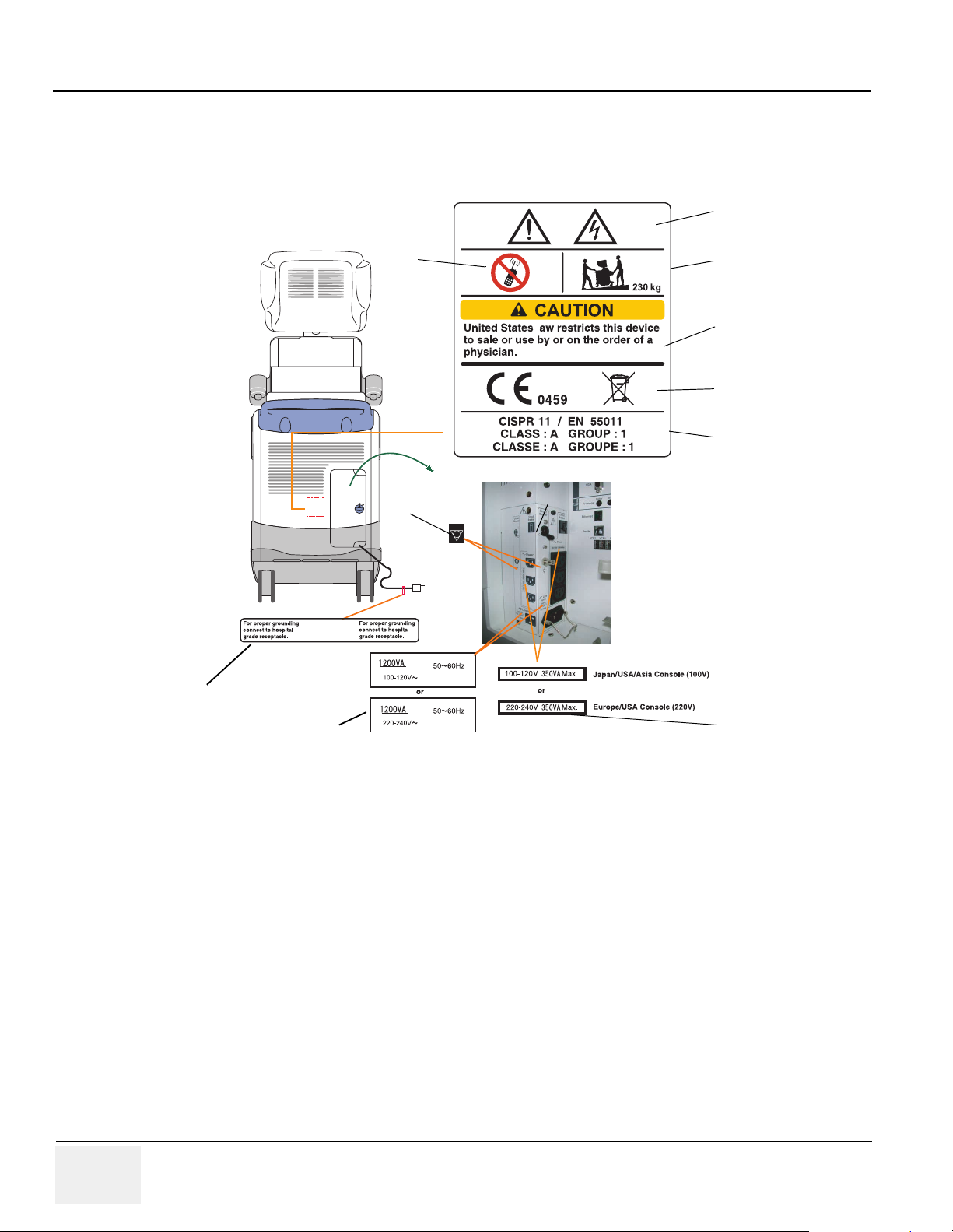
1-3-5 Label Locations (For BT07 or later, including R7.5.x)
NOTE: For the symbols shown in the illustration below, refer to previous pages in this chapter.
(1)
(14)
(21)
(17)
(10)
~
100-120V
220-240V
〜
〜
(15)
GE Yokogawa Medical Systems
(12)
ETL LISTED
CONFORMS TO
UL STD. 2601-1
L
R
D
I
E
S
T
CERTIFIED TO
46477
CAN/CSA C22.2 NO. 601.1
ETL TESTING LABORATORIES INC.
CORTLAND, NEW YORK 13043
(2)
(3)
(4)
(5)
(6)
(7)
(9)
(8)
Japan/USA/Asia Console(100V)
(11)
L
R
D
I
C
E
S
T
Except for R7.5.x
(13)
(2)
(5)
(16)
Label for China
(1)
(3)
(6)
(7)
LCD model ONLY
(18)
CAUTION
CAUTION
Figure 1-1 OUTSIDE MARKINGS OF LOGIQ™ 7 For BT07
or later, including R7.5.x (Back Side)
1-12 Section 1-2 - Important Conventions
Page 35

GE HEALTHCARE
DIRECTION 2286865, REVISION 14 LOGIQ™ 7 SERVICE MANUAL
1-3-5 Label Locations (For BT07 or later, including R7.5.x) (cont’d)
1.) Possible Shock Hazard
2.) Caution for devices near by the equipment
3.) Caution for Transportation
4.) Prescription Devices (For USA Only)
5.) CE Marking of conformity
6.) WEEE mark
7.) CISPR
8.) Voltage Range
9.) Signal Ground Point Label
10.)Power Indication Label
11.)Caution for Grounding Reliability (For USA, Canada and Japan)
12.)ETL Label
13.)Identification and Rating Plate (USA/Asia 120V console)
14.)Identification and Rating Plate (Europe/Asia/USA 220V console)
15.)Identification and Rating Plate (Jpan 100V console)
16.)Identification and Rating Plate (China)
17.)Label that indicates the presence of hazardous substance(s) above the maximum
concentration value.
18.)Identification and Rating Plate (Korean)
19.)Caution label on the monitor
20.)Caution label for the range of motion
21.)This machine should be used in compliance with law. Some jurisdictions restrict certain uses,
such as gender determination. - Korea Console
Section 1-2 - Important Conventions 1-13
Page 36
GE HEALTHCARE
DIRECTION 2286865, REVISION 14 LOGIQ™ 7 SERVICE MANUAL
1-3-6 Label Locations (For BT04, BT06, and V65x)
NOTE: For the symbols shown in the illustration below, refer to previous pages in this chapter.
1.
3.2.
4.
5.
6.
8.
10.
9.
Figure 1-2 OUTSIDE MARKINGS OF LOGIQ™ 7 For BT04
or later (Back Side)
1.) Possible Shock Hazard
2.) Caution for devices near by the equipment
3.) Caution for Transportation
4.) Prescription Devices (For USA Only)
5.) CE Marking of conformity and WEEE mark
6.) CISPR
7.) Voltage Range
8.) Signal Ground Point Label
9.) Power Indication Label
10.)Caution for Grounding Reliability (For USA, Canada and Japan)
7.
7
1-14 Section 1-2 - Important Conventions
Page 37

GE HEALTHCARE
n
DIRECTION 2286865, REVISION 14 LOGIQ™ 7 SERVICE MANUAL
1-3-6 Label Locations (For BT04, BT06, and V65x) (cont’d)
3.
China220VCo
(RightSide)
~
Figure 1-3 OUTSIDE MARKINGS OF LOGIQ™ 7 For BT04
or later
1.) ETL Label
2.) Identification and Rating Plate
3.) SFDA or SDA Label (For China ONLY)
1.
2.
Section 1-2 - Important Conventions 1-15
Page 38

GE HEALTHCARE
DIRECTION 2286865, REVISION 14 LOGIQ™ 7 SERVICE MANUAL
1-3-7 Label Locations (For BT03 or lower)
NOTE: For the symbols shown in the illustration below, refer to previous pages in this chapter.
1.
3.2.
4.
5.
6.
7.
8.
9.
Figure 1-4 OUTSIDE MARKINGS OF LOGIQ™ 7 For BT03
or lower (Back Side)
1.) Possible Shock Hazard
2.) Caution for devices near by the equipment
3.) Caution for Transportation
4.) Prescription Devices (For USA Only)
5.) CE Marking of conformity
6.) CISPR
7.) Voltage Range
8.) Signal Ground Point Label
9.) Power Indication Label
10.)Caution for Grounding Reliability (For USA, Canada and Japan)
10.
1-16 Section 1-2 - Important Conventions
Page 39

GE HEALTHCARE
DIRECTION 2286865, REVISION 14 LOGIQ™ 7 SERVICE MANUAL
1-3-7 Label Locations (For BT03 or lower) (cont’d)
3.
China220VConsole
(RightSide)
~
Figure 1-5 OUTSIDE MARKINGS OF LOGIQ™ 7 For BT03
or lower (Left Side)
1.) ETL Label
2.) Identification and Rating Plate
3.) SDA Label (For China ONLY)
1.
2.
Section 1-2 - Important Conventions 1-17
Page 40

GE HEALTHCARE
DIRECTION 2286865, REVISION 14 LOGIQ™ 7 SERVICE MANUAL
1-3-8 Dangerous Procedure Warnings
Warnings, such as the example below, precede potentially dangerous procedures through our this
manual. Instructions contained in the warnings must be followed.
DANGER
DANGEROUS VOLTAGES, CAPABLE OF CAUSING DEATH, ARE PRESENT IN
THIS EQUIPMENT. USE EXTREME CAUTION WHEN HANDLING, TESTING AND
ADJUSTING.
WARNINGWARNING
WARNINGWARNING
EXPLOSION WARNING: DO NOT OPERATE THE EQUIPMENT IN AN EXPLOSIVE
ATMOSPHERE. OPERATION OF ANY ELECTRICAL EQUIPMENT IN SUCH AN
ENVIRONMENT CONSTITUTES A DEFINITE SAFETY HAZARD.
DO NOT SUBSTITUTE PARTS OR MODIFY EQUIPMENT: BECAUSE OF THE DANGER
OF INTERDICTING ADDITIONAL HAZARDS, DO NOT INSTALL SUBSTITUTE PARTS OR
PERFORM ANY UNAUTHORIZED MODIFICATION OF THE EQUIPMENT.
1-3-9 Lockout/Tagout Requirements (For USA Only)
Follow OSHA Lockout/Tagout requirements by ensuring you are in total control of the electrical Mains
plug.
NOTICE
Energy Control and Power Lockout for LOGIQ™ 7
When servicing parts of the system where there is exposure to voltage greater than 30 Volts:
Unplug the system
Maintain control of the system power plug
There are no test points to verify isolation,
discharge
Beware that the AC Control Box, Front End Processor and Back End Processor may be energized even
if the power is turned off when the cord is still plugged into the AC Outlet.
you must wait for at least 20 seconds for capacitors to
1-3-10 Returning/Shipping Probes and Repair Parts
Equipment being returned must be clean and free of blood and other infectious substances.
GEMS policy states that body fluids must be properly removed from any part or equipment prior to
shipment. GEMS employees, as well as customers, are responsible for ensuring that parts/equipment
have been properly decontaminated prior to shipment. Under no circumstance should a part or
equipment with visible body fluids be taken or shipped from a clinic or site (for example, body coils or
an ultrasound probe).
The purpose of the regulation is to protect employees in the transportation industry, as well as the
people who will receive or open this package.
NOTE: The US Department of Transportation (DOT) has ruled that “items that were saturated and/or
dripping with human blood that are now caked with dried blood; or which were used or intended
for use in patient care” are “regulated medical waste” for transportation purposes and must be
transported as a hazardous material.
1-18 Section 1-2 - Important Conventions
Page 41

GE HEALTHCARE
DIRECTION 2286865, REVISION 14 LOGIQ™ 7 SERVICE MANUAL
1-3-11 How to remove the Ghost CD-ROM
The Ghost CD-ROM (Base System Software Load Image CD-ROM) is mounted on the PC-BOX inside
the scanner using velcro tapes. The upper side of the PC-BOX cover contains sharp edge causing a FE
to have possibility of cutting his hand if he removes the CD-ROM with the PC-BOX cover closed.
PC-BOX Cover
For BT04 or later
Ghost CD-ROM
Sharp Edge
CD-ROMs
NG: WITH PC BOX COVER CLOSED
Do NOT remove the Ghost CD-ROM
when the PC-Box cover is closed.
PC-BOX Cover
OK: WITH PC BOX COVER OPEN
Figure 1-6 How to Remove Ghost CD-ROM
Section 1-2 - Important Conventions 1-19
Page 42

GE HEALTHCARE
DIRECTION 2286865, REVISION 14 LOGIQ™ 7 SERVICE MANUAL
1-3-11 How to remove the Ghost CD-ROM (cont’d)
The sharp edge of the PC Box Cover are chamfered before shipment. However, the Ghost CD-ROM
must be removed with the PC-Box cover open according to the following steps.
1.) Disconnect the DVI-D connector, then remove the four mounting bolts (three hex bolts and one
phillips screw).
Hex bolt
PC Box Cover
Figure 1-7 Removing Bolts
2.) Open the PC box cover and remove the Ghost CD-ROM from the PC box.
PC Box Cover
Hex bolts
Phillips screw
DVI-D connector
Open
Figure 1-8 Removing Ghost CD-ROM
1-20 Section 1-2 - Important Conventions
Ghost CD-ROM
Page 43

GE HEALTHCARE
DIRECTION 2286865, REVISION 14 LOGIQ™ 7 SERVICE MANUAL
Section 1-4 EMC, EMI, and ESD
1-4-1 Electromagnetic Compatibility
Electro Magnetic Compatibility describes a level of performance of a device within its electromagnetic
environment. This environment consists of the device itself and its surroundings including other
equipment, power sources and persons with which the device must interface. Inadequate compatibility
results when a susceptible device fails to perform as intended due interface from its environment or
when the device produces unacceptable levels of mission to its environment. This interface is often
referred to as radio-frequency or electromagnetic interface (RFI/EMI) and can be radiated through
space or conducted over interconnecting power of signal cables. In addition to electromagnetic energy,
EMC also includes possible effects from electrical fields, magnetic fields, electrostatic discharge and
disturbances in the electrical power supply.
1-4-2 Electrostatic Discharge (ESD) Prevention
WARNINGWARNING
DO NOT TOUCH ANY BOARDS WITH INTEGRATED CIRCUITS PRIOR TO TAKING THE
NECESSARY ESD PRECAUTIONS:
1.) Always connect yourself, via an arm-wrist strap, to the dedicated ground
point located on the rear of the scanner (to the left of the power
connector) or a proper frame ground.
2.) Follow general guide lined for handling of electrostatic sensitive
equipment.
1-4-3 CE Compliance
The LOGIQ™ 7 unit conforms to all applicable conducted and radiated emission limits and immunity
from electrostatic discharge, radiated and conducted RF fields, magnetic fields and power line transient
requirements.
Applicable standards are: 47CFR Part18, IEC60601-1-2, and 806-13.
NOTE: For CE Compliance, it is critical that all covers, screws, shielding, gaskets, mesh, clamps, are
in good condition, installed tightly without skew or stress. Proper installation following all
comments noted in this service manual is required in order to achieve full EMC performance.
Section 1-2 - Important Conventions 1-21
Page 44

GE HEALTHCARE
DIRECTION 2286865, REVISION 14 LOGIQ™ 7 SERVICE MANUAL
Section 1-5 Customer Assistance
This system is not repairable by the customer. If this equipment does not work as indicated in the
Operator Manual, please contact your service support center. If the service engineer needs additional
information to repair this equipment, please contact the following address (The necessary information
will be provided to the Service Engineer as needed).
1-5-1 System Manufacture
Table 1-6 System Manufacture
GE YOKOGAWA MEDICAL SYSTEMS
4-7-127 Asahigaoka, Hino-shi, Tokyo, 191-8503
JAPAN
1-5-2 Contact Information
For GE Service:
Table 1-7 Phone Numbers for Customer Assistance
Location Phone Number
USA/ Canada
GE Medical Systems
Ultrasound Service Engineering
4855 W. Electric Avenue
Milwaukee, WI 53219
Customer Answer Center
Latin America
GE Medical Systems
Ultrasound Service Engineering
4855 W. Electric Avenue
Milwaukee, WI 53219
Customer Answer Center
Europe
GE Ultraschall Deutschland GmbH& Co. KG
BeethovenstraBe 239
Postfach 11 05 60, D-42655 Solingen
Germany
Tel: 1-800-321-7937
1-800-682-5327
1-262-524-5698
Fax: +1-414-647-4125
Tel: 1-262-524-5300
1-262-524-5698
Fax: +1-414-647-4125
Tel:
+33 0 130 831 300 - CARDIAC
+33 0 130 831 300 - GENERAL IMAGING
Fax: +49 212 2802 431
Asia (Singapore)
GE Ultrasound Asia
Service Department - Ultrasound
298 Tiong Bahru Road #15-01/06
Central Plaza
Singapore 169730
ASIA (Japan) +65-277-3512
Tel: +65-6277-3512
Fax: +65 6272-3997
1-22 Section 1-5 - Customer Assistance
Page 45

GE HEALTHCARE
DIRECTION 2286865, REVISION 14 LOGIQ™ 7 SERVICE MANUAL
1-5-2 Contact Information (cont’d)
NOTE: If this equipment does not work as indicated in the Operator Manual(s), contact your support
center. Have the system ID number available when you call.
Section 1-5 - Customer Assistance 1-23
Page 46

GE HEALTHCARE
DIRECTION 2286865, REVISION 14 LOGIQ™ 7 SERVICE MANUAL
This page was intentionally left blank.
1-24 Section 1-5 - Customer Assistance
Page 47

GE HEALTHCARE
DIRECTION 2286865, REVISION 14 LOGIQ™ 7 SERVICE MANUAL
Chapter 2
Pre Installation
Section 2-1 Overview
2-1-1 Purpose of this chapter 2
This chapter provides the information required to plan and prepare for the installation of a LOGIQ™ 7.
Included are descriptions of the facility and electrical needs to be met by the purchaser of the unit. A
checklist is also provided at the end of this section to help determine whether the proper planning and
preparation is accomplished before the actual equipment installation is scheduled.
Table 2-1 Contents in Chapter 2
Section Description Page Number
2-1
2-2
2-3
Overview
General Console Requirements
Facility Needs
2-1
2-2
2-7
Section 2-1 - Overview 2-1
Page 48

GE HEALTHCARE
DIRECTION 2286865, REVISION 14 LOGIQ™ 7 SERVICE MANUAL
Section 2-2 General Console Requirements
2-2-1 Console Environmental Requirements
Table 2-2 Environmental Requirements for LOGIQ™ 7 Scanners
Operational Storage Transport
Temperature
Humidity
Pressure
10 - 35 oC
o
50 - 95
F
30 - 80%
non-condensing
700 - 1060hPa 700 - 1060hPa 700 - 1060hPa
o
-10 - 50
14 - 122
30 - 80%
non-condensing
C
o
F
-10 - 50
14 - 122
30 - 80%
non-condensing
Table 2-3 Environmental Requirements for an Ultrasound Room
Item Values
Power Source
Current Rating
Radiation Shielding
Temperature
Humidity
Heat Dissipation
Floor Landing
Floor Condition
Refer to Table 2-4 on page 2-3.
20A (120V, 100V); 7.5A (220-240V) CIRCUIT BREAKER
NONE REQUIRED for ULTRASOUND ENERGY
20-26 DEG. C (68-79 DEG F) for PATIENT COMFORT
50% to 70% for PATIENT COMFORT
3500 BTU/Hr.
Approximately 680 - 800 kg/m2 without Accessories
Gradient: WITHIN 5 degrees
o
C
o
F
Weight
Approximately 225 kg (496lbs) without Accessories
2-2-1-1 Cooling
The cooling requirement for the LOGIQ™ 7 is 3500 BTU/hr. This figure does not include cooling needed
for lights, people, or other equipment in the room. Each person in the room places an additional 300
BTU/hr. demand on the cooling system.
2-2-1-2 Lighting
Bright light is needed for system installation, updates and repairs. However, operator and patient
comfort may be optimized if the room light is subdued and indirect. Therefore a combination lighting
system (dim/bright) is recommended. Keep in mind that lighting controls and diameters can be a source
of EMI which could degrade image quality. These controls should be selected to minimize possible
interface.
2-2 Section 2-2 - General Console Requirements
Page 49

GE HEALTHCARE
DIRECTION 2286865, REVISION 14 LOGIQ™ 7 SERVICE MANUAL
2-2-2 Electrical Requirements
2-2-2-1 Electrical Requirements
NOTE: GE Medical Systems requires a dedicated power and ground for the proper operation of its
Ultrasound equipment. This dedicated power shall originate at the last distribution panel before
the system.
Sites with a mains power system
The dedicated line shall consist of one phase, a neutral (not shared with any other circuit), and
a full size ground wire from the distribution panel to the Ultrasound outlet.
Sites with a mains power system
The dedicated line shall consist of one phase (two lines), not shared with any other circuit, and
a full size ground wire from the distribution panel to the Ultrasound outlet.
Please note that image artifacts can occur, if at any time within the facility, the ground from the
main facility's incoming power source to the Ultrasound unit is only a conduit.
2-2-2-2 LOGIQ™ 7 Power Requirements
The following power line parameters should be monitored for one week before installation. We
recommend that you use an analyzer Dranetz Model 606-3 or Dranetz Model 626:
Table 2-4 Electrical Specifications for LOGIQ™ 7
PARAMETER AREA LIMITS
Voltage Range
Power All applications MAX. 1200 VA
with defined Neutral and Line:
without a defined Neutral:
100V 100 VAC ±10% (90-110 VAC)
220V 220-240 VAC ±10% (198-264 VAC)
120V 120 VAC ±10% (108-132 VAC)
Line Frequency All applications 50/60Hz (±2Hz)
Power Transients All applications
Decaying Oscillation All applications
2-2-2-3 Inrush Current
Inrush Current is not a factor to consider due to the inrush current limiting properties of the power
supplies.
2-2-2-4 Site Circuit Breaker
It is recommended that the branch circuit breaker for the machine be ready accessible.
CAUTION
POWER OUTAGE MAY OCCURE. The LOGIQ™ 7 requires a dedicated single branch circuit. To
avoid circuit overload and possible loss of critical care equipment, make sure you DO NOT have
any other equipment operating on the same circuit.
Section 2-2 - General Console Requirements 2-3
Less than 25% of nominal peak
voltage for less than 1 millisecond for
any type of transient, including line
frequency, synchronous,
asynchronous, or aperiodic
transients.
Less than 15% of peak voltage for
less than 1 millisecond.
Page 50

GE HEALTHCARE
DIRECTION 2286865, REVISION 14 LOGIQ™ 7 SERVICE MANUAL
2-2-2-5 Site Power Outlets
A desiccated AC power outlet must be within reach of the unit without extension cords. Other outlets
adequate for the external peripherals, medical and test equipment needed to support this unit must also
be present within 1 m (3.2 ft.) of the unit. Electrical installation must meet all current local, state, and
national electrical codes.
2-2-2-6 Unit Power Plug
If the unit arrives without the power plug, or with the wrong plug, you must contact your GE dealer or
the installation engineer must supply what is locally required.
2-2-2-7 Power Stability Requirements
Voltage drop-out
Max 10 ms.
Power Transients
Refer Table
2-4 Section 2-2 - General Console Requirements
Page 51

GE HEALTHCARE
DIRECTION 2286865, REVISION 14 LOGIQ™ 7 SERVICE MANUAL
2-2-3 EMI Limitations
Ultrasound machines are susceptible to Electromagnetic Interference (EMI) from radio frequencies,
magnetic fields, and transient in the air wiring. They also generate EMI. The LOGIQ™ 7 complies with
limits as stated on the EMC label. However there is no guarantee that interface will not occur in a
particular installation.
Possible EMI sources should be identified before the unit is installed.
Electrical and electronic equipment may produce EMI unintentionally as the result of defect.
These sources include:
• medical lasers,
• scanners,
• cauterizing guns,
•computers,
•monitors,
•fans,
• gel warmers,
• microwave ovens,
• light dimmers,
• portable phones.
The presence of broadcast station or broadcast van may also cause interference. See for EMI
Prevention tips.
Table 2-5 EMI Prevention/abatement
EMI Rule Details
Be aware of RF sources
Ground the unit
Replace all screws, RF
gaskets, covers, cores
Replace broken RF gaskets
Do not place labels where
RF gaskets touch metal
Use GE specified
harnesses and peripherals
Take care with cellular
phones
Keep the unit at least 5 meters or 15 feet away from other EMI sources. Special shielding
may be required to eliminate interference problems caused by high frequency, high
powered radio or video broadcast signals.
Poor grounding is the most likely reason a unit will have noisy images. Check grounding
of the power cord and power outlet.
After you finish repairing or updating the system, replace all covers and tighten all
screws. Any cable with an external connection requires a magnet wrap at each end.
Install the shield over the front of card cage. Loose or missing covers or RF gaskets allow
radio frequencies to interface with the ultrasound signals.
If more than 20% or a pair of fingers on the RF gaskets are broken, replace the gaskets.
Do not turn on the unit until any loose metallic part is removed.
Never place a label where RF gaskets meet the unit. Otherwise, the gap created will
permit RF leakage. Or, if a label has been found in such a position, move the label.
The interconnect cables are grounded and require ferrite beads and other shielding.
Also, cable length, material, and routing are all important; do not change from what is
specified.
Cellular phones may transmit a 5 V/m signal; that could cause image artifacts.
Properly dress peripheral
cables
Section 2-2 - General Console Requirements 2-5
Do not allow cables to lie across the top of the card cage or hang out of the peripheral
bays. Loop the excess length for peripheral cables inside the peripheral bays. Attach the
monitor cables to the frame.
Page 52

GE HEALTHCARE
DIRECTION 2286865, REVISION 14 LOGIQ™ 7 SERVICE MANUAL
2-2-4 Probes Environmental Requirements
Table 2-6 Operation and storage Temperatures for 2D Probes
Operational Storage Transport
Temperature
Humidity
Pressure
10 - 40 oC
50 - 104
30 - 85%
non-condensing
700 - 1060hPa 700 - 1060hPa 700 - 1060hPa
o
F
o
-10 - 60
14 - 140
30 - 90%
non-condensing
C
o
F
-40 - 60
-40 - 140
30 - 90%
non-condensing
Table 2-7 Operation and storage Temperatures for 4D Probes
Operational Storage Transport
Temperature
Humidity
Pressure
18 - 30 oC
o
64- 86
F
Max. 70%
non-condensing
700 - 1060hPa 700 - 1060hPa 700 - 1060hPa
o
-10 - 50
14 - 122
Max. 90%
non-condensing
C
o
F
-10 - 50
14 - 122
Max. 90%
non-condensing
o
C
o
F
o
C
o
F
2-6 Section 2-2 - General Console Requirements
Page 53

GE HEALTHCARE
DIRECTION 2286865, REVISION 14 LOGIQ™ 7 SERVICE MANUAL
Section 2-3 Facility Needs
2-3-1 Purchaser Responsibilities
The work and materials needed to prepare the site is the responsibility of the purchaser. Delay,
confusion, and waste of manpower can be avoided by completing pre installation work before delivery.
User the Pre Installation checklist to verify that all needed steps have been taken,
Purchaser reasonability includes:
• Procuring the materials required.
• Completing the preparations before delivery of the ultrasound system.
• Paying the costs for any alternations and modifications not specifically provided in the sales
contract.
NOTE: All electrical installation that are preliminary to the positioning of the equipment at the site
prepared for the equipment must be performed by licensed electrical contractors. Other
connections between pieces of electrical equipment, products involved (and the accompanying
electrical installations) are highly sophisticated and special engineering competence is
required. All electrical work on these product must comply with the requirements of applicable
electrical codes. The purchaser of GE equipment must only utilize qualified personnel to
perform electrical servicing on the equipment.
The desire to use a non-listed or customer provided product or to place an approved product further
from the system than the interface kit allows presents challenges to the installation team. To avoid
delays during installation, such variances should be made known to the individuals or group performing
the installation at the earliest possible date (preferable prior to purchase).
The ultrasound suite must be clean proof to delivery of the machine. Carpet is not recommended
because it collects dust and creates static. Potential sources of EMI (electromagnetic interference)
should also be investigated before delivery. Dirt, static, and EMI can negatively impact system.
Section 2-3 - Facility Needs 2-7
Page 54

GE HEALTHCARE
DIRECTION 2286865, REVISION 14 LOGIQ™ 7 SERVICE MANUAL
2-3-2 Required Features
• Dedicated single branch power outlet of adequate amperage (see Table 2-3) meeting all local and
national codes which is located less than 2.5 m (8 ft.) from the unit’s proposed location
• Door opening is at least 76 cm (30 in) wide
• Proposed location for unit is at least 0.3 m (1 ft.) from the wall for cooling
• Power outlet and place for any external peripheral are within 2 m (6.5 ft.) of each other with
peripheral within 1 m of the unit to connect cables.
NOTE: The LOGIQ™ 7 has four outlets inside the unit. One is for the monitor and three for on board peripherals.
• Power outlets for other medical equipment and gel warmer
• Power outlets for test equipment and modem within 1 m (3.2 ft.) of unit
• Clean and protected space to store transducers (in their cases or on a rack)
• Material to safely clean probes (done with a plastic container, never metal)
2-3-3 Desirable Ultrasound Room Facilities
• Door is at least 92 cm (3 ft.) wide
• Circuit breaker for dedicated power outlet is easily accessible
• Sink with hot and cold water
• Receptacle for bio–hazardous waste, like used probe sheaths
• Emergency oxygen supply
• Storage for linens and equipment
• Nearby waiting room, lavatory, and dressing room
• Dual level lighting (bright and dim)
• Lockable cabinet ordered by GE for its software and proprietary manuals
2-8 Section 2-3 - Facility Needs
Page 55

GE HEALTHCARE
DIRECTION 2286865, REVISION 14 LOGIQ™ 7 SERVICE MANUAL
2-3-4 Recommended and Alternate Ultrasound Room Layout
Recommended standard floor plan and a minimal floor plan for ultrasound equipment:
LOGIQ
LOGIQ
Figure 2-1 RECOMMENDED ULTRASOUND ROOM
LAYOUT
Section 2-3 - Facility Needs 2-9
Page 56

GE HEALTHCARE
DIRECTION 2286865, REVISION 14 LOGIQ™ 7 SERVICE MANUAL
2-3-5 Networking Pre-installation Requirements
2-3-5-1 Purpose of DICOM Network Function
DICOM services provide the operator with clinically useful features for moving images and patient
information over a hospital network. Examples of DICOM services include the transfer of images to
workstations for viewing or transferring images to remote printers. As an added benefit, transferring
images in this manner frees up the on-board monitor and peripherals, enabling viewing to be done while
scanning continues. With DICOM, images can be archived, stored, and retrieved faster, easier, and at
a lower cost.
2-3-5-2 DICOM Option Pre-installation Requirements
To configure the LOGIQ™ 7 to work with other network connections, the site’s network administrator
must provide some necessary information.
Information must include:
• A host name, local port number, AE Title, IP address and Net Mask for the LOGIQ™ 7.
• The IP addresses for the default gateway and other routers at the site for ROUTING
INFORMATION.
• The host name, IP address, port and AE Title for each device the site wants connected to the
LOGIQ™ 7 for DICOM APPLICATION INFORMATION. A field for the make (manufacturer) and
the revision of the device, is also included. This information may be useful for solving errors.
2-10 Section 2-3 - Facility Needs
Page 57

GE HEALTHCARE
DIRECTION 2286865, REVISION 14 LOGIQ™ 7 SERVICE MANUAL
2-3-5-2 DICOM Option Pre-installation Requirements (cont’d)
.
.
LOGIQ™ 7
Host Name
Local Port
IP Address
..
.
AE Title
ROUTING INFORMATION
ROUTER1
ROUTER2
ROUTER3
DICOM APPLICATION INFORMATION
NAME
Store 1
Store 2
Store 3
Store 4
Destination
IP Addresses
...
...
...
MAKE/REVISION IP ADDRESSES PORTAE TITLE
Net Mask
Default
...
GATEWAY IP Addresses
...
...
...
...
...
...
...
...
Store 5
Store 6
Worklist
Storage
Commit
MPPS
...
...
...
...
...
Figure 2-2 Worksheet for DICOM Network Information
Section 2-3 - Facility Needs 2-11
Page 58

GE HEALTHCARE
DIRECTION 2286865, REVISION 14 LOGIQ™ 7 SERVICE MANUAL
This page was intentionally left blank.
2-12 Section 2-3 - Facility Needs
Page 59

GE HEALTHCARE
DIRECTION 2286865, REVISION 14 LOGIQ™ 7 SERVICE MANUAL
Chapter 3
Installation
Section 3-1 Overview
3-1-1 Purpose of Chapter 3
This chapter contains information needed to install the unit. Included are references to a procedure that
describes how to receive and unpack the equipment and how to file a damage or loss claim.
How to prepare the facility and unit of the actual installation, and how to check and test the unit, probes,
and external peripherals for electrical safety are included in this procedure. Also included in this section
are guidelines for transporting the unit to a new site.
Table 3-1 Contents in Chapter 3
Section Description Page Number
3-1
3-2
3-3
3-4
3-5
Overview
Receiving and Unpacking the Equipment
Preparing for Installation
Completing the Installation
Installation Paperwork
3-1-2 Average Installation Time
Table 3-2 Average Installation Time
Description Average Installation Time Comments
Unpacking the scanner
Scanner wo/options
DICOM Option
InSite Option
0.5 hour
0.5 hour
0.5 hour
0.5 hour
3-1
3-3
3-10
3-11
3-18
Dependant on the configuration that is required
Dependant on the amount of configuration
The LOGIQ™ 7 has been designed to be installed and checked out by an experienced service
technician in approximately four hours. LOGIQ™ 7 consoles with optional equipment may take slightly
longer.
Section 3-1 - Overview 3-1
Page 60

GE HEALTHCARE
DIRECTION 2286865, REVISION 14 LOGIQ™ 7 SERVICE MANUAL
3-1-3 Installation Warnings
1.) Since the LOGIQ™ 7 weighs approximately 225 kg. (496 lb) without options, preferably two people
should unpack it. Two people are also preferable for installing any additional bulky items.
2.) There are no operator serviceable components. To prevent shock, do not remove any covers or
panels. Should problems or malfunctions occur, unplug the power cord. Only qualified service
personnel should carry out servicing and troubleshooting.
3.) After being transported, the unit may be very cold or hot. If this is the case, allow the unit to
acclimate before you turn it on. It requires one hour for each 2.5×C increment it's temperature is
below 10×C or above 40×C.
CAUTION
Equipment damage possibility. Turning the system on without acclimation after arriving at site
may cause the system to be damaged.
Table 3-3 Time for Settlement
60 55 50 45 40 35 30 25 20 15 10 5 0 -5 -10 -15 -20 -25 -30 -35 -40
°C
140 131 122 113 104 96 86 77 68 59 50 41 32 23 14 5 -4 -13 -22 -31 -40
°F
864200000002468101214161820
hrs
3-1-3-1 Brake Pedal Operation
WARNINGWARNING
R
REMEMBER: IF THE FRONT CASTER SWIVEL LOCK IS ENGAGED FOR
TRANSPORTATION, PRESSING THE RELEASE PEDAL ONCE EDISENGAGES THE
SWICEL LOCK. YOU MUST DEPRESS THE RELEASE PEDAL A SECOND TIME TO
ENGAGE THE BRAKE.
3-2 Section 3-1 - Overview
Page 61

GE HEALTHCARE
DIRECTION 2286865, REVISION 14 LOGIQ™ 7 SERVICE MANUAL
Section 3-2 Receiving and Unpacking the Equipment
When a new system arrives, check that any components are not damaged and are not in short supply.
If shipping damage or shortage occurs, contact the address shown in Chapter 1.
Example shown:
LOGIQ 7 system
Outer Sleeve
Monitor Sleeve
For CRT
Box for
Peripherals
Front Cushion
Slope
Cap
Plastic Joint
Monitor Sleeve
For LCD
Rear Cushion
Plastic Band
Skid
Figure 3-1 Unpacking Procedures
Unpacking Procedures:
1.) Cut the two Metal Bands.
2.) Lift the Cap up and off.
3.) Remove the six (6) Plastic Joints from the Outer Sleeves.
4.) Remove the Outer Sleeves.
5.) Remove the Monitor Sleeve.
6.) Remove the Box for Peripherals.
7.) Remove the Front and Rear Cushions.
8.) Slide out and set up the Slope.
9.) Unlock the brakes by stepping down on the brake pedal in front, then carefully roll the LOGIQ™
7 rear side first off the Skid.
Section 3-1 - Overview 3-3
Page 62

GE HEALTHCARE
DIRECTION 2286865, REVISION 14 LOGIQ™ 7 SERVICE MANUAL
Section 3-2 Receiving and Unpacking the Equipment (cont’d)
NOTE: Check the shipping container for special instructions. Verify that the container is intact. In some
cases a secondary container may be used. If so, ask the carrier for unpacking instructions.
NOTICE
For the protection of LCD monitor, re-use the packing sleeve whenever possible, in case of shipment
after unpacking.
Secure the LCD Sleeve with adhesive tape after
placing it to the proper location.
Adhesive Tape (Each side)
Pull over the sleeve to the LCD arm.
Turn over the LCD monitor, and
place the sleeve to the location
above. Make sure LCD arm is
locked.
Figure 3-2 Labels on Package
3-4 Section 3-1 - Overview
Make sure the LCD arm hinge is
placed inside of the protective pad.
Note: These labels are attached onto the
shipping box, defining environment at
which consoles are to be transported or
stored.
Page 63

GE HEALTHCARE
DIRECTION 2286865, REVISION 14 LOGIQ™ 7 SERVICE MANUAL
3-2-1 Safety Reminders
DANGER
CAUTION
CAUTION
CAUTION
CAUTION
CAUTION
CAUTION
CAUTION
WHEN USING ANY TEST INSTRUMENT THAT IS CAPABLE OF OPENING THE
AC GROUND LINE (I.E., METER’S GROUND SWITCH IS OPEN), DO NOT TOUCH
THE UNIT!
Two people should unpack the unit because of its weight. Two people are required whenever a
part weighing 19kg (35 lb.) or more must be lifted.
If the unit is very cold or hot, do not turn on its power until it has had a chance to acclimate to
its operating environment.
To prevent electrical shock, connect the unit to a properly grounded power outlet. Do not use a
three to two prong adapter. This defeats safety grounding.
Do NOT wear the ESD wrist strap when you work on live circuit and more than 30 V peak is
present.
Do not use a 20 Amp to 15 Amp adapter on the 120 Vac unit’s power cord. This unit requires a
dedicated 20 A circuit and can have a 15 A plug if the on board peripherals do not cause the unit
to draw more than 14.0 amps.
Do not operate this unit unless all board covers and frame panels are securely in place. System
performance and cooling require this.
OPERATOR MANUAL(S)
The User Manual(s) should be fully read and understood before operating the LOGIQ™ 7 and
kept near the unit for quick reference.
CAUTION
CAUTION
CAUTION
ACOUSTIC OUTPUT HAZARD
Although the ultrasound energy transmitted from the LOGIQ™ 7 probe is within FDA limits,
avoid unnecessary exposure. Ultrasound energy can produce heat and mechanical damage.
Do not lift the unit by the Keyboard. Equipment damage may result.
The crate with the LOGIQ™ 7 weighs approximately 340 kg. (749.7 lb) Be prepared for a sudden
shift of weight as the unit is removed from its base (pallet)
Section 3-1 - Overview 3-5
Page 64

GE HEALTHCARE
DIRECTION 2286865, REVISION 14 LOGIQ™ 7 SERVICE MANUAL
3-2-2 Moving into Position
CAUTION
CAUTION
CAUTION
Do not lift the unit by the Keyboard.
Do not tilt the unit more than 5 degrees to avoid tipping it over.
To avoid injury by tipping over. Set the monitor to the lowest position before moving.
Equipment Damage Possibility. Lifting the console by holding covers may damage the covers.
Do not lift the console by holding any covers.
In general, a single adult can move the LOGIQ™ 7 along an even surface with no steep grades. At least
two people should move the machine when large humps, grooves, or grades will be encountered. (It is
better to pull from the rear rather than push from the front of the unit). Before moving, store all loose
parts in the unit. Wrap transducers in soft cloth or foam to prevent damage.
Although LOGIQ™ 7 is a compact and mobile machine, two people should move it over rough surfaces
or up and down grades.
For LCD Model ONLY:
Always lock the LCD monitor arm before removing the LCD monitor. This prevents the monitor
arm from being suddenly and unexpectedly extended when removing the LCD monitor. Failure
to heed this warning may result in personal harm, harm to others or death..
Arm Lock (LCD Model ONLY)
3-6 Section 3-1 - Overview
Page 65

GE HEALTHCARE
DIRECTION 2286865, REVISION 14 LOGIQ™ 7 SERVICE MANUAL
3-2-3 LCD Monitor Tilt Caution
CAUTION
Do NOT put your hand here! Your fingers might be pinched when adjusting angle of the LCD
monitor.
For R7.5.x 19inch LCD system
Figure 3-3 LCD Monitor Tilt Caution
Section 3-1 - Overview 3-7
Page 66

GE HEALTHCARE
DIRECTION 2286865, REVISION 14 LOGIQ™ 7 SERVICE MANUAL
3-2-4 LCD Monitor Swing CautionLCD Monitor Tilt Caution
CAUTION
CAUTION
Arm can be swung 180 degree left and right, and stick out from the side frame. Pay attention to
the location from the wall in the room for room layout, and notice the attention to customer for
Examination Table side.
LCD will hit the KBD in case of moving over the right/left side.
3-8 Section 3-1 - Overview
Page 67

GE HEALTHCARE
DIRECTION 2286865, REVISION 14 LOGIQ™ 7 SERVICE MANUAL
3-2-5 LCD Monitor Removal Caution
CAUTION
Always lock the LCD monitor arm before removing the LCD monitor. This prevents the monitor
arm from being suddenly and fastly extended when removing the LCD monitor. Failure to heed
this warning may result in personal harm, harm to others or death.
Arm Lock (LCD Model ONLY)
3-2-6 Shipping Delivery Requirements
Do NOT hold the scanner at the LCD monitor or rotaing arm using the belt as shown. Always hold it at
the body part of the console.
CAUTION
Always hold the scanner
at the body.
Figure 3-4 Shipping Delivery Requirements
Section 3-1 - Overview 3-9
Page 68

GE HEALTHCARE
DIRECTION 2286865, REVISION 14 LOGIQ™ 7 SERVICE MANUAL
Section 3-3 Preparing for Installation
3-3-1 Verify Customer Order
Compare items received by the customer to that which is listed on the delivery order. Report any items
that are missing, back ordered or damaged.
3-3-2 Physical Inspection
3-3-2-1 System Voltage Settings
• Verify that the scanner is set to the correct voltage. The Voltage settings for the LOGIQ™ 7 Scanner
is found on the label onto the rear lower of the scanner.
WARNINGWARNING
CONNECTING A LOGIQ™ 7 SCANNER TO THE WRONG VOLTAGE LEVEL WILL MOST
LIKELY DESTROY THE SCANNER.
WARNINGWARNING
PROTECTIVE EARTH MUST BE TAKEN WHEN CONNECTING AC POWER CABLE
(200V) WITHOUT ITS PLUG TO WALL OUTLET.
3-3-3 EMI Protection
This Unit has been designed to minimize the effects of Electro Magnetic Interference (EMI). Many of the
covers, shields, and screws are provided primarily to protect the system from image artifacts caused by
this interference. For this reason, it is imperative that all covers and hardware are installed and secured
before the unit is put into operation.
3-10 Section 3-3 - Preparing for Installation
Page 69

GE HEALTHCARE
DIRECTION 2286865, REVISION 14 LOGIQ™ 7 SERVICE MANUAL
Section 3-4 Completing the Installation
3-4-1 Probe (Transducer) Connection
1.) Connect a transducer to the upper transducer receptacle as follows:
NOTICE
NOTE: It is not necessary to turn OFF power to connect or disconnect a transducer.
To make effective use of the memory space:
1. When a scanner has one linear probe, it must be connected to the most left receptacle.
2. When a scanner has several linear probes, they must be connected from the left to the right.
a.) Ensure that the transducer twist lock lever to the horizontal position.
b.) Insert the transducer connector on the receptacle guide pin until it touches the receptacle
mating surface.
c.) Twist the transducer twist lock lever to vertical position to lock it in place. Twist the lever to the
horizontal position to disconnect the transducer.
2.) Connect the main power cable to a hospital grade power receptacle with the proper rated voltage
checked during pre installation. Never use a three-to-two prong adapter; this defeats the safety
ground.
Section 3-4 - Completing the Installation 3-11
Page 70

GE HEALTHCARE
DIRECTION 2286865, REVISION 14 LOGIQ™ 7 SERVICE MANUAL
3-4-2 Optional Peripherals/Peripheral Connection
Depending on the customer order, the peripheral(s) already has been installed onto the scanner before
shipment. If it does not, select the proper location to install the peripherals, following the table below.
Console Top
Device Room
Figure 3-5 Optional Peripherals/Peripheral Connection
Location for
peripheral
Consle Top Not used Not used VCR or DVD recorder
Device Room Used
One peripheral
(Color printer ONLY)
One peripheral (VCR
or DVD recorder)
Used Color Pinter
Two peripherals
3-12 Section 3-4 - Completing the Installation
Page 71

GE HEALTHCARE
DIRECTION 2286865, REVISION 14 LOGIQ™ 7 SERVICE MANUAL
3-4-2 Optional Peripherals/Peripheral Connection (cont’d)
Check if the fixing belts are loosen. If it is, tighten the belts again to secure the peripheral(s). If
necessary, remove the peripheral from the device room to tighten the belts.
Connect the related cables
between the peripheral and
Belts
Belts
LOGIQ 7 if they are NOT connected each other.
Belts
Figure 3-6 How to Hold Peripherals
3-4-2-1 Approved on-board peripherals
Refer to Section 5-3 Peripheral Compatibility.
Section 3-4 - Completing the Installation 3-13
Page 72

GE HEALTHCARE
DIRECTION 2286865, REVISION 14 LOGIQ™ 7 SERVICE MANUAL
3-4-2-1 Approved on-board peripherals (cont’d)
Connecting Cables
CAUTION
Equipment damage possibility. Be sure to use the following recommended connecting cables to connect
recording devices and a network with LOGIQ™ 7 console.
Table 3-4 List of Connecting Cables
Name Part No. Figure NOTE
Power Supply Cable P9509EE
USB Serial Bridge
Cable
AV Cable 2119874
Mini-Plug Cable P9509BE
RS232C Cable
Cross
RS232C Cable
Straight
2304621
The followings are the cables for BT04 ore lower system ONLY.
2305550
2305549
Connected to power
For converting the signal of
RS232C cable to USB cable:
connected to VCR1 on the Rear
Panel
Connected to Video-In/Out on the
Rear Panel
Shutter control signals:
connected to B/W Printer
For control signals:
connected to Serial Bridge Cable
For control signals:
connected to Serial Bridge Cable
BNC Cable 2297053
USB Cable 2324360
SCSI cables
(UP-D50 ONLY)
2375479
3-4-2-2 Reference off-board peripherals and options
None.
For control signal:
connected to Composite B/W
Connected to USB port.
Connected toSCSI port and SCSI
Cable Connector.
3-14 Section 3-4 - Completing the Installation
Page 73

GE HEALTHCARE
DIRECTION 2286865, REVISION 14 LOGIQ™ 7 SERVICE MANUAL
3-4-3 Available Probes
See in specification in the LOGIQ™ 7 Reference Manual for Probes and intended use.
See Chapter 9 - Renewal Parts for Part Numbers to be used when ordering new or replacement probes.
Table 3-5 List of Transducers supported (All models)
Material of
Probe Name
Headshell
Area of Using TYPE Catalog Number Part Number
3C PES ABDOMINAL CONVEX
5C PES ABDOMINAL CONVEX
8C PBT
E8C
M7C PBT ABDOMINAL CONVEX
M12L PBT SMALL PARTS LINEAR
7L NORYL
10L NORYL SUPERFICIAL LINEAR
10S ABS PEDIATRIC SECTOR
3.5C NORYL ABDOMINAL CONVEX
3.5CS NORYL ABDOMINAL CONVEX
NORYL
PBT
NEONATAL
PEDIATRICS
TRANSVAGINAL MICRO-CONVEX
ABDOMINAL
SUPERFICIAL
MICRO-CONVEX
LINEAR
H79802P
H40412LB
H79822P
H40412LA
H79792P
H40412LJ
H79852P
H40412LE
H79832P
H40412LC
H79842P
H40412LD
H79862P
H40412LF
H79872P
H40412LG
H79922P
H4901PC
H79812P
H4901PE
H78042P
H40412LK
2286353
2286354
2294515
2294516
2348093
2348094
2294640
2294641
2294513
2294514
2294510
2294511
2294520
2294521
2294522
2294523
2309478
2298589
2303215
2050357
2380854
2051858
3S NORYL CARDIOLOGY SECTOR
i12L ABS INTRAOPERATIVE LINEAR
M3S PBT CARDIOLOGY SECTOR
TRASOPHAGEAL FOR
6T-OR-TEE PU: PolyUrethane
7S PBT CARDIOLOGY SECTOR
BE9C PBT TRANSRECTAL MICRO-CONVEX
T739 NORYL INTRAOPERATIVE LINEAR
4D3C_L PBT ABDOMINAL CONVEX Volume H44801G
ADULT
CARDIOLOGY
SECTOR
H79632P
H4701SZ
H79322P
H4012L
H79892P
H45011SZ
H79932P
H45521DX
H78082P
H40422LB
H40412LW
H76572SR
H40212LM
Section 3-4 - Completing the Installation 3-15
2348878
2323337
2270556
2264883
2293726
2378099
5131947
KN100068
2355698
2347471
2389381
2389382
2259245
2259246
5121652
KTZ195893
Page 74

GE HEALTHCARE
DIRECTION 2286865, REVISION 14 LOGIQ™ 7 SERVICE MANUAL
Table 3-5 List of Transducers supported (All models)
Material of
Probe Name
Headshell
Area of Using TYPE Catalog Number Part Number
4D10L PBD SUPERFICIAL LINEAR Volume H44801GB
4C PBT ABDOMINAL CONVEX H4904PC
12L Noryl SUPERFICIAL LINEAR H40412LH
P2D ABS CARDIOLOGY CWD H4830JE TE100024
P6D --- SUPERFICIAL CWD H4830JG TQ100002
NOTE: PES: Polyethersulfone NORYL: Modified Polyphenylene Oxide PU: Polyurethane
PBT: Polybutylene Terephthalate ABS: Acrylonitrile Butadiene Styrene
NOTE: Some probes indicated on the table above have two different part numbers. The upper row
shows the part numbers of probes for Japan. The lower row shows the part numbers of probes
for regions other than Japan. Probes which have only one part number are not available in
Japan.
The following transducers, additional to ones listed in Table 3-6, are supported by V65x and later LOGIQ
7 models.
Table 3-6 List of Transducers supported by V65x and later
Material of
Probe Name
Headshell
Area of Using TYPE Catalog Number Part Number
5121651
KTZ156836
5131944
5123455
2295375
2295377
9L PBT
4DE7C PBT OB Gyn Urology CONVEX Volume H44801GA 5121650
VASCULAR SMALL
PARTS
LINEAR H40412LT 5131433
The following transducers, additional to ones listed in Table 3-7, are supported by R7.5.x and later
LOGIQ 7 models.
Table 3-7 List of Transducers supported by R7.5.x and later
Material of
Probe Name
3CRF PU: PolyUrethane ABDOMINAL MICRO-CONVEX H40442LP
Headshell
Area of Using TYPE Catalog Number Part Number
The following transducers, additional to ones listed in Table 3-8, are supported by BT09 and later
LOGIQ 7 models.
Table 3-8 List of Transducers supported by BT09 and later
Material of
Probe Name
11L PBT SUPERFICIAL LINEAR
Headshell
Area of Using TYPE Catalog Number Part Number
H78842P
H40412LY
5214820
5196216
5251881
5171885
3-16 Section 3-4 - Completing the Installation
Page 75

GE HEALTHCARE
DIRECTION 2286865, REVISION 14 LOGIQ™ 7 SERVICE MANUAL
3-4-4 Video Specification
Table 3-9 Video Specifications
CRT LCD
800x600
Timing Parameter
Horizontal Rate [kHz] 46.88 Horizontal Rate [kHz] 64
Horizontal Period [µs] 21.33 Horizontal Period [µs] 15.625
Pixel Clock [MHz] 49.50 Pixel Clock [MHz] 108
H Blank Width [µs] 5.17 H Blank Width [µs] 3.778 (408dots)
H Sync Width [µs] 1.62 H Sync Width [µs] 1.037 (112dots)
H Front Porch [µs] 0.32 H Sync Front Porch [µs] 0.444 (48dots)
Active Horizontal Period [µs] 16.16 Active Horizontal Period [µs]
Vertical Rate [Hz] 75.00 Vertical Rate [Hz] 60.0
Vertical Period [ms] 13.33 Vertical Period [ms]
V Sync Width [lines=ms] 25=0.53 V Sync Front Porch [ms] 0.016 (1 line)
V Front Porch [lines=µs] 3=64.00 Equalization Porch None
Equalization Gate [lines=µs] 1=21.3 Lines: Field/Frame 1066
Lines: Field/Frame 625 Active Lines/Frame 1024
Active Lines/Frame 600
75Hz
Timing Parameter
1280 x 1024
60Hz
11.852
(1280dots)
16.67
(1066lines)
3-4-5 Software Option Configuration
3-4-5-1 Onsite check and configuration
Select Utility > Admin > System Admin and check the option software to be installed.
Section 3-4 - Completing the Installation 3-17
Page 76

GE HEALTHCARE
DIRECTION 2286865, REVISION 14 LOGIQ™ 7 SERVICE MANUAL
Section 3-5 Installation Paperwork
NOTE: During and after installation, the documentation (i.e. Users Manual, Installation Manuals...) for
the peripheral units must be kept as part of the original system documentation. This will ensure
that all relevant safety and user informations are available during the operation and service of
the complete system.
3-5-1 Peripherals/Accessories Connector Panel
LOGIQ™ 7 peripherals and accessories can be properly connected using the rear connector panel
located behind the rear door, front connector panel located next to the video printer, and Footswitch
connector located bottom of the OP panel.
3-18 Section 3-5 - Installation Paperwork
Page 77

GE HEALTHCARE
DIRECTION 2286865, REVISION 14 LOGIQ™ 7 SERVICE MANUAL
3-5-1-1 Rear Panel Connector
Located on the rear panel are video input and output connectors, audio input and output, camera
expose connectors, footswitch connector power connector and control connections for VCR, printer,
and service tools.
This section indicates the pin assignment for each connector.
Rear Pannel Connector for BT04 and later models
1
S-Video
In
LR
Video In
Audio
In
Audio
Out
LR
Cmpst
S-Video
Video Out
Out
Out
B/WColor
Circuit
Circuit
Breaker
Breaker
Circuit
Circuit
Breaker
Breaker
Power
Power
VGA
Camera
Expose
8
c/
Re
Ethernet
Insite
2
B/WColor
7
5
6
VCR2 VCR1 Service
3
100-120V 350VA Max
AC Line Input
AC Line Input
1200VA
1200VA
-
-
240V
120V
220
100
50/ 60Hz
50/ 60Hz
Figure 3-7 Rear Pannel Connector (BT04 or later)
Section 3-5 - Installation Paperwork 3-19
Page 78

GE HEALTHCARE
DIRECTION 2286865, REVISION 14 LOGIQ™ 7 SERVICE MANUAL
3-5-1-1 Rear Panel Connector (cont’d)
Rear Pannel Connector for BT03 or lower
1
2
3
USB1.1 (USB compatible)
or (USB + USB Serial Bridge
+ RS232C)
USB1.1 (USB compatible)
or (USB + USB Serial Bridge
+ RS232C)
USB1.1 (USB compatible)
or (USB + USB Serial Bridge
8
7
4
+ RS232C)
(Reserved for future use)
5
6
Figure 3-8 Rear Panel Connector (BT03 or lower)
NOTE: Each outer (case) ground line of peripheral/accessory connectors are protectively grounded.
Signal ground lines are not isolated, except the Service port (3). All of signal lines (include signal
GND) of the Service port are isolated.
The specified peripherals/accessories only can be connected to the USB ports.
3-20 Section 3-5 - Installation Paperwork
Page 79

GE HEALTHCARE
DIRECTION 2286865, REVISION 14 LOGIQ™ 7 SERVICE MANUAL
3-5-1-1 Rear Panel Connector (cont’d)
1
Pin Assignment of S-Video Connector
Connector: S-Terminal, 4-pin
4
2
2
Pin Assignment of VGA Connector
3
Table 3-10 Pin Assignment of S-Video Connector
1
Pin No Output/Input Signal Description
1 SVIDEO OUT/IN YG Y (Luma) GND
2 SVIDEO OUT/IN CG C (Chroma) GND
3 SVIDEO OUT/IN Y Y (Luma) SIGNAL
4 SVIDEO OUT/IN C C (Chroma) SIGNAL
Connector: Shrank D-Sub, 15-pin
5
10
15
1
6
Table 3-11 Pin Assignment of VGA Connector
11
Pin No Output Signal Description
1 IO VGA OUT1 R Red
2 IO VGA OUT1 G Green
3 IO VGA OUT1 B Blue
6 IO VGA OUT1 RG Reg GND
7 IO VGA OUT1 GG Green GND
8 IO VGA OUT1 BG Blue GND
13 IO VGA OUT1 HS H Sync
14 IO VGA OUT1 VS V Sync
Others GND GND
3
Pin Assignment of Service/VCR 1/VCR 2 Connector, USB1.1
Connector: 4 pin
1 2 3 4
Table 3-12 Pin Assignment of Service/VCR 1/VCR 2 Connector
Pin No Output Signal Description
1 VBUSn Power Supply
2 Dn Data (-)
3 Dn Data (+)
4 GNDn Power Ground
Section 3-5 - Installation Paperwork 3-21
Page 80

GE HEALTHCARE
DIRECTION 2286865, REVISION 14 LOGIQ™ 7 SERVICE MANUAL
3-5-1-1 Rear Panel Connector (cont’d)
4
Pin Assignment of Digital Int. Connector
2 4 6
Connector: 6-pin
Table 3-13 Pin Assignment of IEEE-1394 Connector)
1 3 5
5
Pin Assignment of Ethernet
Connector: RJ-45 Modular, 8-pin
Table 3-14 Pin Assignment of Ethernet Connector
8 1
Pin No Output Signal Description
1 VP 1394 Power Supply
2 VG 1394 Power Ground
3 TPB 1394 Data B (-)
4 TPB 1394 Data B (+)
5 TPA 1394 Data A (-)
6 TPA 1394 Data A (+)
Pin No Output Signal Description
1 ETHER TD Ethernet TD+
6
Pin Assignment of Insite
Connector: RJ-11 Modular, 6-pin
Table 3-15 Pin Assignment of Insite Connector
8 1
2 ETHER TD Ethernet TD-
3 ETHER RD Ethernet RD+
6 ETHER RD Ethernet RD-
Others NC Non-connection
Pin No Output Signal Description
2 TEL L4 Telephone L4
3 TEL L2 Telephone L2
4 TEL L1 Telephone L1
5 TEL L3 Telephone L3
Others NC Non-connection
3-22 Section 3-5 - Installation Paperwork
Page 81

GE HEALTHCARE
DIRECTION 2286865, REVISION 14 LOGIQ™ 7 SERVICE MANUAL
3-5-1-1 Rear Panel Connector (cont’d)
7
Pin Assignment for Camera B/W
Table 3-16 Pin Assignment of Mini-Jack for Controlling B/W Camera
Pin No Output Signal
1PRINT
2 Signal GND
NOTE: Output level of control signals indicated in the above tables are TTL level.
8
Pin Assignment of Insite
Table 3-17 Pin Assignment of Mini-Jack for Controlling Color Camera
Pin No Output Signal
3-5-1-2 Front Connector Panel
Located on the front panel are Microphone, LED, and Reset.
For BT03 or lower
Microphone
LED
(HD access)
Figure 3-9 Front Connector Panel
1 SHUTTER
2 Signal GND
Note:USB1.1. Some
systems do NOT have this
port. If your system has
this port, do NOT use this
port! Instead, use the
USB port located at the
rear connector panel.
Reset
For BT04 or later
USB2.0
You can use
the serial port.
Serial
Section 3-5 - Installation Paperwork 3-23
Page 82

GE HEALTHCARE
DIRECTION 2286865, REVISION 14 LOGIQ™ 7 SERVICE MANUAL
3-5-1-3 B/W Printer Connector Panel
Table 3-18 Pin Assignment of Mini-Jack for Controlling B/W Printer
Pin No Output Signal
1PRINT
2 Signal GND
3-5-1-4 Footswitch Connector Panel
3
4
2
1
5
Round 5 pin connector.
Table 3-19 Pin Assignment of Mini-Jack for Footswitch
Pin No Output Signal
1SW1-WH
2SW2-RD
3SW3-GN
4 SW1-BK, SW2-BK, SW3-BK
5Frame GND
NOTE: Output level of control signals indicated in the above tables are TTL level.
3-24 Section 3-5 - Installation Paperwork
Page 83

GE HEALTHCARE
DIRECTION 2286865, REVISION 14 LOGIQ™ 7 SERVICE MANUAL
This page was intentionally left blank.
Section 3-5 - Installation Paperwork 3-25
Page 84

GE HEALTHCARE
DIRECTION 2286865, REVISION 14 LOGIQ™ 7 SERVICE MANUAL
3-26 Section 3-5 - Installation Paperwork
Page 85

GE HEALTHCARE
DIRECTION 2286865, REVISION 14 LOGIQ™ 7 SERVICE MANUAL
Chapter 4
Functional Checks
Section 4-1 Overview
4-1-1 Purpose for Chapter 4
This chapter provides procedures for quickly checking major functions of the LOGIQ™ 7 console,
diagnostics by using the built-in service software, and power supply adjustments.
Table 4-1 Contents in chapter 4
Section Description Page Number
NOTICE
4-1
4-2
4-3
4-4
4-5
4-6
4-7
Most of the information pertaining to this Functional Checks chapter is found in the LOGIQ™ 7 Quick
Overview
General Procedure
Functional Checks
Application Turnover Check List
Diagnostics
Power Supply
Site Log
Guide (Direction Number 2291859-100).
Look for the letters (QG) after a section in the Table of Contents to determine if the information is in this
chapter or in the Quick Guide.
4-1-2 Special Equipment Required
• An empty (blank) MO Disk.
• At least one transducer.
(normally you should check all the transducers used on the system.)
4-1
4-2
4-20
4-27
4-28
4-29
4-30
Section 4-1 - Overview 4-1
Page 86

GE HEALTHCARE
DIRECTION 2286865, REVISION 14 LOGIQ™ 7 SERVICE MANUAL
Section 4-2 General Procedure
CAUTION
SYSTEM REQUIRES ALL COVERS
Operate this unit only when all board covers and frame panels are securely in place. The covers
are required for safe operation, good system performance and cooling purposes.
4-2-1 Lockout/Tagout Requirements
Follow OSHA Lockout/Tagout requirements by ensuring you are in total control of the plug.
4-2-2 Power On/Boot Up
NOTE: After turning off the system, wait at least ten seconds before turning it on again. The system
may not be able to boot if power is recycled too quickly.
4-2-2-1 Power Up
1.) Connect the Main Power Cable at the rear of the System.
WARNINGWARNING
PROTECTIVE EARTH MUST BE TAKEN WHEN CONNECTING AC POWER CABLE
(200V) WITHOUT ITS PLUG TO WALL OUTLET.
2.) Connect the Main Power cable to an appropriate mains power outlet.
3.) Switch ON the Main Circuit Breaker at the rear of the System.
Main Circuit Breaker
Main Power Cable
Figure 4-1 Circuit Breaker
When power is applied to the Scanner, and the Rear Circuit breaker is turned ON, Power is distributed
to the Fans, Control panel, Monitor, Internal and External I/O’s, Cage Boards, Peripherals and the
Backend Processor. When the Power ON/OFF key is pressed once, the Backend Processor starts and
its software code is distributed to initiate the scanner.
4-2 Section 4-2 - General Procedure
For BT04 or lator
Page 87

GE HEALTHCARE
DIRECTION 2286865, REVISION 14 LOGIQ™ 7 SERVICE MANUAL
4-2-2-1 Power Up (cont’d)
4.) Press the ON/OFF
key at the front of the System once.
Figure 4-2 Power On/Off Standby Switch Location
4-2-2-2 Power Up Sequence
NOTE: For consoles with BEP4 (BT09), power switch lamp is darker compared to existing BT04-BT07
consoles with BEP3. This is NOT abnormality and system will function normally regardless of
the brightness of the power button.
1.) The Start Up Screen will be shown on the Monitor display when the system is turned ON.
Figure 4-3 Start Up Screen
Section 4-2 - General Procedure 4-3
Page 88
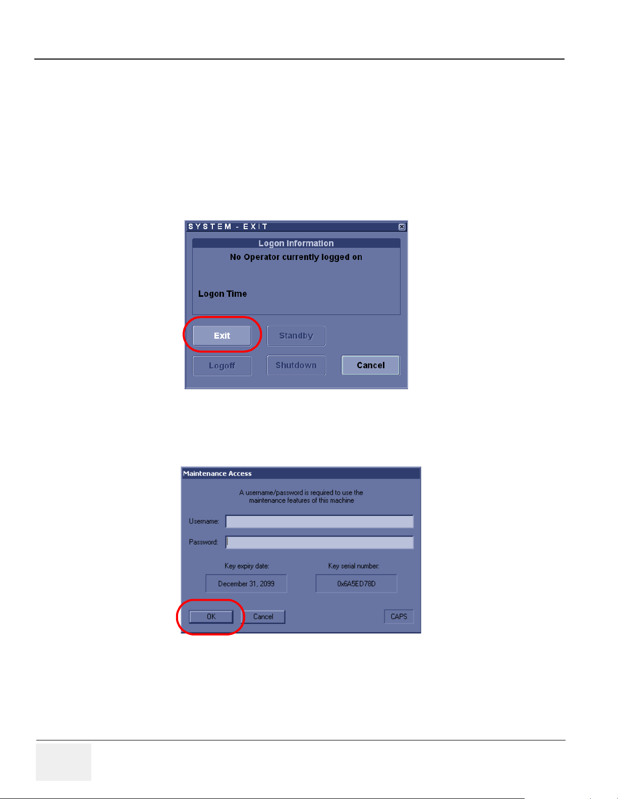
GE HEALTHCARE
DIRECTION 2286865, REVISION 14 LOGIQ™ 7 SERVICE MANUAL
2.) After initialization is complete, all lighted buttons on the Control Panel light and the default B-Mode
screen or Patient screen (no probes are connected) is displayed on the monitor display.
4-2-2-3 Entering Maintenance Mode
4-2-2-3-1 R6.2.x or later
1.) Insert the service dongle into any USB port.
2.) Wait for scanner boot-up.
3.) Tap ON/OFF the power switch.
4.) Click on Exit.
Figure 4-4 Clicking on Exit
5.) Enter the proper password to enter the maintenance mode.
6.) Click on OK.
Figure 4-5 Clicking on OK
4-4 Section 4-2 - General Procedure
Page 89

GE HEALTHCARE
DIRECTION 2286865, REVISION 14 LOGIQ™ 7 SERVICE MANUAL
4-2-2-3 Entering Maintenance Mode (cont’d)
7.) Click on maintenance.
Figure 4-6 Clicking on Maintetance
8.) Click on Exit to window.
7
7
Figure 4-7 Clicking on Exit to Window
Section 4-2 - General Procedure 4-5
Page 90

GE HEALTHCARE
DIRECTION 2286865, REVISION 14 LOGIQ™ 7 SERVICE MANUAL
4-2-2-3 Entering Maintenance Mode (cont’d)
4-2-2-3-2 R 4.x.x to R6.0.x
1.) The Start Up Screen will be shown on the Monitor display when the system is turned ON.
2.) The “Probing for maintenance access” dialog appears. Enter Password, then click on OK.
3.) Then Start Loader display will be shown on the Monitor display.Click on Maintenance.
Figure 4-8 Clicking on Mainttenance
4.) Click on Exit to Windows in maintenace diaglog window.Then the scanner is booted up
automatically.
4-2-2-3-3 R2.x.x to R4.x.x
1.) Insert the service dongle in the Service port located at the rear panel.
2.) The Start Up Screen will be shown on the Monitor display when the system is turned ON.
3.) Then Start Loader display will be shown on the Monitor display. Then the scanner is booted up
automatically.
NOTE: To enter the Maintenance Mode, select Maintenance button.
Figure 4-9 Start Application Window
NOTE: Start is selected automatically when it time out.
4-6 Section 4-2 - General Procedure
Page 91

GE HEALTHCARE
DIRECTION 2286865, REVISION 14 LOGIQ™ 7 SERVICE MANUAL
4-2-3 Power Shutdown
Purpose: This is a description on how to Shutdown the system.
4-2-3-1 Complete Power Down
1.) Press the ON/OFF
2.) Switch OFF the Main Circuit Breaker at the rear of the system Refer to Figure 4-1.
3.) Disconnect the Main Power Cable if needed. Refer to Figure 4-1.
key at the front of the System for about two (2) seconds. Refer to Figure 4-2.
4-2-4 System Stand-by
LOGIQ 7 is available with Stand-by option. The option is effective in reducing the scanner power up
time, when used as portable device.
Users must follow the procedures in order to use the option.
NOTE: Do not use more than 20 Stand-by mode continuously without shutting down the system. The
scanner must be powered off daily.
1.) Press the POWER switch once.
2.) Select Standby.At this point, both the touch panel and the main monitor will go blank. Keyboard
lights also turns dark. Power switch button will be illuminated.
NOTICE
NOTICE
Standby
Figure 4-10 Selecting Standby
3.) Wait more than 20seconds.
Do not disconnect the power cable immediately.
4.) Plug off the power cord from wall outlet.
Do not press the Power button without connecting the power cable.
5.) Transport the scanner as required, but re-connect to power outlet within 20 minutes. If not powered
system may shut down due to loss of sustained battery power.
6.) Connect the scanner to a wall electrical outlet.
Section 4-2 - General Procedure 4-7
Page 92

GE HEALTHCARE
q
DIRECTION 2286865, REVISION 14 LOGIQ™ 7 SERVICE MANUAL
4-2-4 System Stand-by (cont’d)
7.) To power up the scanner, tap POWER button momentary, and wait for power up. It will
approximately 45seconds for the scanner to power up.
NOTICE
Do not press the Power button long time, as it will cause the system to power down.
Stand-by Sequence
Stand-by
uence
Se
Wait
ON
Press POWER button
Select "Standby"
Che ck Monitor
OFF
Check Touch
Panel OFF
OFF
Connect to electrical outlet
(Power Cord)
Stan dby may be
faile d
Note1 : BT09 Release with BEP4 Hardware have "Blinking Power Button"
capability to indicate the console in Stand-by condition. For BEP3 and earlier,
Power button must be "OFF" before disconnecting the power cord.
ON
Che ck POWER
button
(Note 1)
OFF or Blinking
Wait more than 20 seconds
Disconnect Power Cord
Figure 4-11 Stand-by Sequence
4-8 Section 4-2 - General Procedure
Press POWER button
Wait 5 se conds
Scanner Start up completion
in 45 seconds
Page 93

GE HEALTHCARE
DIRECTION 2286865, REVISION 14 LOGIQ™ 7 SERVICE MANUAL
4-2-5 Using CD-R/MOD/DVD Drive
4-2-5-1 Using CD-R or DVD Drive
NOTICE
NOTICE
CD-R Drive
Never move the unit with a disk in the CD-R or DVD because the drive actuator will not be
locked and the CD-R or DVD could break.
1.) Push the EJECT
2.) Put the disk onto the disk tray.
3.) Press the EJECT
4.) There are a number of methods to eject a disk from the CD-R or DVD. Ejection is automatic in some
cases. Manual ejection methods, listed in preferred order of use, are:
a.) Press EJECT
b.) Press and hold EJECT
c.) Mechanical ejection. Insert the end of a paper clip into the hole while system power is OFF.
Avoid mechanical ejection whenever possible. Mechanical ejection leaves the actuator
unlocked and the MOD susceptible to damage if moved. If forced to use this method, reboot
the system, then insert and eject a known good disk using one of the other methods.
button, the disk tray will appear.
button to insert the disk into the CD-R or DVD device.
button on the CD-R or DVD while system is ON.
button while the system is booting.
Eject Button
Mechanical
Eject Hole
DVD Drive
Figure 4-12 CD-R or DVD drive
NOTE: Be careful not to scratch the disk when wiping it off for cleaning.
NOTE: Keeping your CD-R or DVD disc in an original CD-R or DVD case or caddy all the time will
prevent it from becoming dirty or damaged.
NOTE: Media Requirement:
Please be aware of the following regarding saving data to DVD-R on R6.0.x.:
Use x8 or x16 speed compatible DVD-R. When it is the upgraded R6.0.x system from R4.x.x.
or prior version, some systems have a number "4" or "5" printed on the disc tray of the media
drive and others don't. If there is no number printed on the disc tray, use x4 or x16 speed
compatible DVD-R.
Section 4-2 - General Procedure 4-9
Page 94

GE HEALTHCARE
DIRECTION 2286865, REVISION 14 LOGIQ™ 7 SERVICE MANUAL
4-2-5-2 Using MOD Drive
1.) Before installing an MO disk in the MOD, check the MO disk for loose hardware or damaged labels
which could jam inside the MO Drive. Also ensure that the slide switch in one corner of the disk is
set so that the disk is write enabled (disk hole closed).
2.) Insert the disk into the MOD with the label facing up.
NOTICE
NOTICE
MO Drive
Never move the unit with a disk in the MOD because the drive actuator will not be locked and
the MOD could break.
3.) The are a number of methods to eject a disk from the MOD. Ejection is automatic in some cases.
Manual ejection methods, listed in preferred order of use, are:
a.) Press EJECT
b.) Press and hold EJECT
button on the MOD while system is ON.
button while the system is booting.
c.) Mechanical eject. Insert the end of a paper clip into the hole while system power is OFF.
Avoid mechanical ejection whenever possible. Mechanical ejection leaves the actuator
unlocked and the MOD susceptible to damage if moved. If forced to use this method, reboot
the system, then insert and eject a known good disk using one of the other methods.
Eject Button
Mechanical
Eject Hole
Figure 4-13 MOD drive
4-10 Section 4-2 - General Procedure
MO Drive
Page 95

GE HEALTHCARE
DIRECTION 2286865, REVISION 14 LOGIQ™ 7 SERVICE MANUAL
4-2-6 Archiving and Loading Presets for BT07 (Including R7.5.x)
NOTE: Always save presets before any software reload. This ensures the presets loaded after the software
reload are as up–to–date as possible.
All user presets except changes to Summary, Anatomy, and Biometry pages, can be saved on an CDR/MO/DVD-R disk for reloading on the system.
NOTICE
Presets should NOT be saved on the same CD-R/MO/DVD-R disk as images. The Archive Menu
lists the images but does NOT list the presets stored on a CD-R/MO/DVD-R disk.
4-2-6-1 Regional Preset - General (Supported from BT07)
NOTICE
Do not attempt to change/use Regional Preset buttons for Upgraded BT07. For Upgrade BT07 always
use Factory Default in order to avoid preset conflict. Contact application specialist for details.
This feature has the capability to have factory default preset defined by the following regions; Americas,
Europe, Asia, or Japan.
Table 4-2
Presets Unique to Regions Presets NOT unique to Regions
System Imaging (System>System Imaging page)
System Measure (System->System Measure page)
Imaging Settings (Imaging page)
Comments (Comments page)
Body Patterns (Body Patterns page)
Application (Application page)
3D/4D (3D/4D page)
Measure (Measure page) : Utility/Measure Advanced and
Doppler preset
System General (System>General page)
Connectivity (Connectivity page)
Reports (Report page)
Measure (Measure page) : Utility/Measure M&A and OB
Table preset
Section 4-2 - General Procedure 4-11
Page 96

GE HEALTHCARE
DIRECTION 2286865, REVISION 14 LOGIQ™ 7 SERVICE MANUAL
4-2-6-2 Using Regional Preset
Regional Preset is selected during Application Load (Refer to 8-8-13 - Installing R7.x.x Application
Software for details).
Current Regional Preset is displayed under Utility > System > About .
NOTICE
Figure 4-14 Current Regional Preset
For Upgraded BT07, this field always shows "None" as Region Preset is feature available for pure BT07
and onward.
Factory Default Regional Preset can be re-loaded from Utility > Systme > About > Additional About.
Figure 4-15 Factory Default Regional Preset
4-12 Section 4-2 - General Procedure
Page 97

GE HEALTHCARE
DIRECTION 2286865, REVISION 14 LOGIQ™ 7 SERVICE MANUAL
4-2-6-3 Cautions Using Regional Preset
• Do not attempt to modify Regional Preset on Upgraded BT07.
• Backup/Restore function should be used between the same region systems. Unexpected setting
may result if you restore the preset files to another region setting system.
CAUTION
When software is upgraded (from BT07 and on) re-loaded or upgraded (from BT07and on), make sure
to select the factory default. Because the preset region information in globalconfig.res file shall not be
upgraded, if different region presets are loaded, then it may cause conflict between system setting and
region presets.
4-2-6-4 Formatting CD-R/DVD-R Disk
1.) Insert an empty (blank) CD-R/DVD-R disk into the CD-R/DVD-R device.
2.) Access to the Utility Menu on the Touch Panel, and select Connectivity>Removable Media.
3.) Select the removable media from media list.
4.) Type a name for the removable media in Label field.
5.) Select Format button.
Figure 4-16 Selecting Format Button
Section 4-2 - General Procedure 4-13
Page 98

GE HEALTHCARE
DIRECTION 2286865, REVISION 14 LOGIQ™ 7 SERVICE MANUAL
4-2-6-5 Archiving Presets to an CD-R/DVD-R Disk
1.) Insert an empty (blank) formatted CD-R/DVD-R disk into the CD-R/DVD-R device.
2.) Access to the Utility Menu on the Touch Panel, and select System>Backup/Restore. The Backup
screen will be shown on the monitor.
3.) Select the item to back up either from Resource Files.
4.) Select the media to locate the items.
5.) Click on Backup. The backup status for each item is displayed on the Result column.
Figure 4-17 Clicking on Backup
6.) Make sure “Finished OK” is displayed on the Result column.
4-14 Section 4-2 - General Procedure
Page 99

GE HEALTHCARE
DIRECTION 2286865, REVISION 14 LOGIQ™ 7 SERVICE MANUAL
4-2-6-6 Loading Presets from an CD-R/DVD-R disk
1.) Insert the CD-R/DVD-R disk with the archived Presets into the CD-R/DVD-R.
2.) Access to the Utility Menu on the Touch Panel, and select System>Backup/Restore. The Restore
sheet will be shown on the monitor.
3.) Select the item to restore either from resource Files.
4.) Click on Restore. A message to make sure the restore process is displayed on the monitor. Click
OK. The restore status for each item is displayed on the Result column.
Figure 4-18 Clicking on Restore
5.) Make sure “Finished OK” is displayed on the Result column.
4-2-6-7 Regional Preset - Files
Service Tip: The system shall have each region preset files into:
• Americas : C:/Pegasus/target/resources/Pegasus/ Americas/userdefs/
• Europe: C:/Pegasus/target/resources/Pegasus/Europe/userdefs/
• Asia: C:/Pegasus/target/resources/Pegasus/ Asia/userdefs/
• Japan: C:/Pegasus/target/resources/Pegasus/Japan/userdefs/
When region is selected, Region preset files are copied to:
• C:/Pegasus/target/resources/idunn/userdefs/
Section 4-2 - General Procedure 4-15
Page 100

GE HEALTHCARE
DIRECTION 2286865, REVISION 14 LOGIQ™ 7 SERVICE MANUAL
4-2-7 Archiving and Loading Presets for BT06/V65x or lower
NOTE: Always save presets before any software reload. This ensures the presets loaded after the software
reload are as up–to–date as possible.
All user presets except changes to Summary, Anatomy, and Biometry pages, can be saved on an CDR/MO/DVD-R disk for reloading on the system.
NOTICE
4-2-7-1 Formatting CD-R/MO/DVD-R Disk
Presets should NOT be saved on the same CD-R/MO/DVD-R disk as images. The Archive Menu
lists the images but does NOT list the presets stored on a CD-R/MO/DVD-R disk.
1.) Insert an empty (blank) CD-R/MO/DVD-R disk into the CD-R/MO/DVD-R device.
2.) Access to the Utility Menu on the Touch Panel, and select Connectivity>Removable Media or
Tools.
Figure 4-19 Formatting Removable Media1
4-16 Section 4-2 - General Procedure
 Loading...