

General Electric LOGIQ 400 SERVICE MANUAL_SM_2127661_9 Cell Counter Preventative Maintenance
Page 1

2127661
Revision 9
LOGIQ 400
Service Manual
Copyright1995, 1996, 1997, 1998, 1999, 2000 by General Electric Company
Page 2

LOGIQ 400 SERVICE MANUALGE MEDICAL SYSTEMS
REV 9
2127661
LIST OF EFFECTIVE PAGES
REV DATE PRIMARY REASON FOR CHANGE
0 July 27, 1995 Initial release
1 October 6, 1995 Software version 2.10 release, error correction
2 July 10, 1996 Software version 3.00 release, error correction
3 March 10, 1997 Software version 3.10 release, error correction
4 December 17, 1997 LOGIQ 400CL release, error correction
5 June 19, 1998 Software version 3.40 and 3.41 for LOGIQ 400CL release and error correction
6 April 21, 1999 Software version 4.01y and 4.02y release and error correction
7 September 17, 1999 Additional information for SGMS Manufacturing
8 October 15, 1999 Software version 4.31y and 4.32y release and error correction
9 March 17, 2000 Software version 5.01 release and error correction
P AGE REV PAGE REV PAGE REV PAGE REV PAGE REV
Title page 9. . . . . . . . . .
GE Logo page –. . . . . .
P9030CB 2. . . . . . . . . . .
P9030CC 4. . . . . . . . . .
P9030CD 0. . . . . . . . . .
A9. . . . . . . . . . . . . . . . . .
i8. . . . . . . . . . . . . . . . . . .
ii to x 9. . . . . . . . . . . . . .
Chapter 1
1–1 8. . . . . . . . . . . . . . . .
1–2 to 1–3 0. . . . . . . . . .
1–4 2. . . . . . . . . . . . . . . .
1–5 to 1–8 8. . . . . . . . . .
1–9 7. . . . . . . . . . . . . . . .
1–10 to 20 8. . . . . . . . . .
Chapter 2
2–1 5. . . . . . . . . . . . . . . .
2–2 to 2–4 0. . . . . . . . . .
2–5 5. . . . . . . . . . . . . . . .
2–6 to 2–9 0. . . . . . . . . .
2–10 9. . . . . . . . . . . . . . .
2–11 to 2–16 0. . . . . . . .
Chapter 3
3–1 9. . . . . . . . . . . . . . . .
3–2 0. . . . . . . . . . . . . . . .
3–3 to 3–16 9. . . . . . . . .
Chapter 4
4–1 6. . . . . . . . . . . . . . . .
4–2 0. . . . . . . . . . . . . . . .
4–3 2. . . . . . . . . . . . . . . .
4–4 1. . . . . . . . . . . . . . . .
4–5 0. . . . . . . . . . . . . . . .
4–6 1. . . . . . . . . . . . . . . .
4–7 0. . . . . . . . . . . . . . . .
4–8 to 4–10 1. . . . . . . . .
4–11 to 4–13 0. . . . . . . .
4–14 1. . . . . . . . . . . . . . .
4–15 0. . . . . . . . . . . . . . .
4–16 6. . . . . . . . . . . . . . .
4–17 0. . . . . . . . . . . . . . .
4–18 5. . . . . . . . . . . . . . .
4–19 1. . . . . . . . . . . . . . .
4–20 to 4–24 5. . . . . . .
4–25 to 4–26 9. . . . . . .
4–27 to 4–32 5. . . . . . .
4–33 to 4–46 6. . . . . . .
Chapter 5
5–1 6. . . . . . . . . . . . . . . .
5–2 0. . . . . . . . . . . . . . . .
5–3 to 5–4 1. . . . . . . . . .
5–5 9. . . . . . . . . . . . . . . .
5–6 to 5–7 6. . . . . . . . . .
5–8 to 5–9 9. . . . . . . . . .
5–10 to 5–1 1 6. . . . . . . .
5–12 to 5–13 0. . . . . . .
5–14 to 5–15 2. . . . . . .
5–16 to 5–17 6. . . . . . .
5–18 9. . . . . . . . . . . . . . .
5–19 8. . . . . . . . . . . . . . .
5–20 9. . . . . . . . . . . . . . .
Chapter 6
6–1 to 6–288 9. . . . . . .
Chapter 7
7–1 5. . . . . . . . . . . . . . . .
7–2 0. . . . . . . . . . . . . . . .
7–3 4. . . . . . . . . . . . . . . .
7–4 to 7–6 2. . . . . . . . . .
7–7 to 7–20 5. . . . . . . . .
Chapter 8
8–1 to 8–3 5. . . . . . . . . .
8–4 0. . . . . . . . . . . . . . . .
8–5 to 8–7 5. . . . . . . . . .
8–8 to 8–15 0. . . . . . . . .
8–16 5. . . . . . . . . . . . . . .
8–17 0. . . . . . . . . . . . . . .
8–18 5. . . . . . . . . . . . . . .
8–19 to 8–20 4. . . . . . .
8–21 5. . . . . . . . . . . . . . .
8–22 0. . . . . . . . . . . . . . .
8–23 5. . . . . . . . . . . . . . .
8–24 0. . . . . . . . . . . . . . .
8–25 to 8–26 5. . . . . . .
8–27 0. . . . . . . . . . . . . . .
8–28 5. . . . . . . . . . . . . . .
8–29 0. . . . . . . . . . . . . . .
8–30 to 8–88 5. . . . . . .
A
Page 3

LOGIQ 400 SERVICE MANUALGE MEDICAL SYSTEMS
REV 8
2127661
TABLE OF CONTENTS
SECTION TITLE PAGE
T ABLE OF CONTENTS i. . . . . . . . . . . . . . . . . . . . . . . . . . . . . . . . . . . . . . . . . . . . . . . . . . . . . . . . . . . . . . . . . .
CHAPTER 1 – INTRODUCTION
1–1 SER VICE MANUAL CONTENTS 1–3. . . . . . . . . . . . . . . . . . . . . . . . . . . . . . . . . . . . . . . . . . . . . . . . . . . . . . .
1–2 SAFETY 1–4. . . . . . . . . . . . . . . . . . . . . . . . . . . . . . . . . . . . . . . . . . . . . . . . . . . . . . . . . . . . . . . . . . . . . . . . . . . . .
1–2–1 Warnings 1–4. . . . . . . . . . . . . . . . . . . . . . . . . . . . . . . . . . . . . . . . . . . . . . . . . . . . . . . . . . . . . . . . . . .
1–2–2 Specifications 1–17. . . . . . . . . . . . . . . . . . . . . . . . . . . . . . . . . . . . . . . . . . . . . . . . . . . . . . . . . . . . . .
1–3 EMC (Electromagnetic Compatibility) 1–18. . . . . . . . . . . . . . . . . . . . . . . . . . . . . . . . . . . . . . . . . . . . . . . . . . .
1–3–1 EMC Performance 1–18. . . . . . . . . . . . . . . . . . . . . . . . . . . . . . . . . . . . . . . . . . . . . . . . . . . . . . . . . .
1–3–2 Notice upon Installation of Product 1–18. . . . . . . . . . . . . . . . . . . . . . . . . . . . . . . . . . . . . . . . . . . .
1–3–3 General Notice 1–19. . . . . . . . . . . . . . . . . . . . . . . . . . . . . . . . . . . . . . . . . . . . . . . . . . . . . . . . . . . . .
1–3–4 Countermeasures against EMC-related Issues 1–19. . . . . . . . . . . . . . . . . . . . . . . . . . . . . . . . . .
1–3–5 Notice on Service 1–19. . . . . . . . . . . . . . . . . . . . . . . . . . . . . . . . . . . . . . . . . . . . . . . . . . . . . . . . . . .
1–4 ADDRESS 1–20. . . . . . . . . . . . . . . . . . . . . . . . . . . . . . . . . . . . . . . . . . . . . . . . . . . . . . . . . . . . . . . . . . . . . . . . . .
CHAPTER 2 – INSTALLATION
2–1 PREINSTALLATION 2–3. . . . . . . . . . . . . . . . . . . . . . . . . . . . . . . . . . . . . . . . . . . . . . . . . . . . . . . . . . . . . . . . . .
2–1–1 Introduction 2–3. . . . . . . . . . . . . . . . . . . . . . . . . . . . . . . . . . . . . . . . . . . . . . . . . . . . . . . . . . . . . . . . .
2–1–2 Power Line Requirements 2–3. . . . . . . . . . . . . . . . . . . . . . . . . . . . . . . . . . . . . . . . . . . . . . . . . . . . .
2–1–3 Physical Specifications 2–4. . . . . . . . . . . . . . . . . . . . . . . . . . . . . . . . . . . . . . . . . . . . . . . . . . . . . . .
2–1–4 Recommended Ultrasound Room Layout 2–5. . . . . . . . . . . . . . . . . . . . . . . . . . . . . . . . . . . . . . .
2–2 INSTALLA TION 2–8. . . . . . . . . . . . . . . . . . . . . . . . . . . . . . . . . . . . . . . . . . . . . . . . . . . . . . . . . . . . . . . . . . . . . . .
2–2–1 Introduction 2–8. . . . . . . . . . . . . . . . . . . . . . . . . . . . . . . . . . . . . . . . . . . . . . . . . . . . . . . . . . . . . . . . .
2–2–2 Average Installation Time 2–8. . . . . . . . . . . . . . . . . . . . . . . . . . . . . . . . . . . . . . . . . . . . . . . . . . . . .
2–2–3 Installation Warnings 2–8. . . . . . . . . . . . . . . . . . . . . . . . . . . . . . . . . . . . . . . . . . . . . . . . . . . . . . . . .
2–2–4 Checking the Components 2–8. . . . . . . . . . . . . . . . . . . . . . . . . . . . . . . . . . . . . . . . . . . . . . . . . . . .
2–2–5 Unpacking LOGIQ 400 2–9. . . . . . . . . . . . . . . . . . . . . . . . . . . . . . . . . . . . . . . . . . . . . . . . . . . . . .
2–2–6 Probe Cable Arm Installation 2–12. . . . . . . . . . . . . . . . . . . . . . . . . . . . . . . . . . . . . . . . . . . . . . . . .
2–2–7 MTZ Probe Holder Installation 2–13. . . . . . . . . . . . . . . . . . . . . . . . . . . . . . . . . . . . . . . . . . . . . . . .
2–2–8 Transducer Connection 2–13. . . . . . . . . . . . . . . . . . . . . . . . . . . . . . . . . . . . . . . . . . . . . . . . . . . . . .
2–2–9 Powering-Up Procedure 2–14. . . . . . . . . . . . . . . . . . . . . . . . . . . . . . . . . . . . . . . . . . . . . . . . . . . . .
2–2–10 Moving into Position 2–15. . . . . . . . . . . . . . . . . . . . . . . . . . . . . . . . . . . . . . . . . . . . . . . . . . . . . . . . .
2–2–11 Adjusting System Clock 2–15. . . . . . . . . . . . . . . . . . . . . . . . . . . . . . . . . . . . . . . . . . . . . . . . . . . . . .
2–2–12 Product Locator Installation Card 2–16. . . . . . . . . . . . . . . . . . . . . . . . . . . . . . . . . . . . . . . . . . . . . .
i
T ABLE OF CONTENTS
Page 4

LOGIQ 400 SERVICE MANUALGE MEDICAL SYSTEMS
REV 9
SECTION TITLE PAGE
2127661
CHAPTER 3 – SYSTEM CONFIGURATION
3–1 INTRODUCTION 3–3. . . . . . . . . . . . . . . . . . . . . . . . . . . . . . . . . . . . . . . . . . . . . . . . . . . . . . . . . . . . . . . . . . . . .
3–2 DIMENSIONS 3–3. . . . . . . . . . . . . . . . . . . . . . . . . . . . . . . . . . . . . . . . . . . . . . . . . . . . . . . . . . . . . . . . . . . . . . . .
3–3 ELECTRICAL SPECIFICATIONS 3–6. . . . . . . . . . . . . . . . . . . . . . . . . . . . . . . . . . . . . . . . . . . . . . . . . . . . . . .
3–3–1 Power Supply 3–6. . . . . . . . . . . . . . . . . . . . . . . . . . . . . . . . . . . . . . . . . . . . . . . . . . . . . . . . . . . . . . .
3–3–2 Facility Power Receptacle 3–6. . . . . . . . . . . . . . . . . . . . . . . . . . . . . . . . . . . . . . . . . . . . . . . . . . . . .
3–4 ST ORAGE AND OPERATION REQUIREMENTS 3–6. . . . . . . . . . . . . . . . . . . . . . . . . . . . . . . . . . . . . . . . .
3–5 OPTIONAL PERIPHERALS 3–7. . . . . . . . . . . . . . . . . . . . . . . . . . . . . . . . . . . . . . . . . . . . . . . . . . . . . . . . . . . .
3–5–1 Peripherals/Accessories Connector Panel 3–7. . . . . . . . . . . . . . . . . . . . . . . . . . . . . . . . . . . . . . .
3–5–2 List of Optional Peripherals 3–11. . . . . . . . . . . . . . . . . . . . . . . . . . . . . . . . . . . . . . . . . . . . . . . . . . .
3–5–3 Power Consumption of Optional Peripherals 3–15. . . . . . . . . . . . . . . . . . . . . . . . . . . . . . . . . . . .
3–6 VIDEO SPECIFICATIONS 3–16. . . . . . . . . . . . . . . . . . . . . . . . . . . . . . . . . . . . . . . . . . . . . . . . . . . . . . . . . . . .
CHAPTER 4 – FUNCTIONAL CHECKS
4–1 INTRODUCTION 4–3. . . . . . . . . . . . . . . . . . . . . . . . . . . . . . . . . . . . . . . . . . . . . . . . . . . . . . . . . . . . . . . . . . . . .
4–1–1 Required Equipment 4–3. . . . . . . . . . . . . . . . . . . . . . . . . . . . . . . . . . . . . . . . . . . . . . . . . . . . . . . . . .
4–2 FUNCTIONAL CHECK PROCEDURES 4–4. . . . . . . . . . . . . . . . . . . . . . . . . . . . . . . . . . . . . . . . . . . . . . . . .
4–2–1 Basic Controls 4–4. . . . . . . . . . . . . . . . . . . . . . . . . . . . . . . . . . . . . . . . . . . . . . . . . . . . . . . . . . . . . . .
4–3 DIAGNOSTICS 4–10. . . . . . . . . . . . . . . . . . . . . . . . . . . . . . . . . . . . . . . . . . . . . . . . . . . . . . . . . . . . . . . . . . . . . .
4–3–1 Service Software Menu 4–10. . . . . . . . . . . . . . . . . . . . . . . . . . . . . . . . . . . . . . . . . . . . . . . . . . . . . .
4–3–2 Diagnosis Test Menu 4–11. . . . . . . . . . . . . . . . . . . . . . . . . . . . . . . . . . . . . . . . . . . . . . . . . . . . . . . .
4–3–3 Utility Menu 4–16. . . . . . . . . . . . . . . . . . . . . . . . . . . . . . . . . . . . . . . . . . . . . . . . . . . . . . . . . . . . . . . .
4–4 POWER SUPPLY ADJUSTMENTS 4–37. . . . . . . . . . . . . . . . . . . . . . . . . . . . . . . . . . . . . . . . . . . . . . . . . . . .
4–4–1 Power Supply Access 4–38. . . . . . . . . . . . . . . . . . . . . . . . . . . . . . . . . . . . . . . . . . . . . . . . . . . . . . .
4–4–2 Power Supply Adjustment Procedure 4–40. . . . . . . . . . . . . . . . . . . . . . . . . . . . . . . . . . . . . . . . . .
CHAPTER 5 – DIAGRAMS
5–1 INTRODUCTION 5–3. . . . . . . . . . . . . . . . . . . . . . . . . . . . . . . . . . . . . . . . . . . . . . . . . . . . . . . . . . . . . . . . . . . . .
5–2 LOGIQ 400 SYSTEM 5–3. . . . . . . . . . . . . . . . . . . . . . . . . . . . . . . . . . . . . . . . . . . . . . . . . . . . . . . . . . . . . . . .
5–3 BLOCK DIAGRAM 5–4. . . . . . . . . . . . . . . . . . . . . . . . . . . . . . . . . . . . . . . . . . . . . . . . . . . . . . . . . . . . . . . . . . . .
5–4 WIRING DIAGRAM 5–8. . . . . . . . . . . . . . . . . . . . . . . . . . . . . . . . . . . . . . . . . . . . . . . . . . . . . . . . . . . . . . . . . . .
5–5 POWER SUPPLY BLOCK DIAGRAM 5–12. . . . . . . . . . . . . . . . . . . . . . . . . . . . . . . . . . . . . . . . . . . . . . . . . .
5–6 POWER SUPPLY2 BLOCK DIAGRAM 5–14. . . . . . . . . . . . . . . . . . . . . . . . . . . . . . . . . . . . . . . . . . . . . . . . .
5–7 POWER SUPPLY2 BLOCK DIAGRAM 5–16. . . . . . . . . . . . . . . . . . . . . . . . . . . . . . . . . . . . . . . . . . . . . . . . .
5–8 CIRCUIT BOARD DESCRIPTION 5–18. . . . . . . . . . . . . . . . . . . . . . . . . . . . . . . . . . . . . . . . . . . . . . . . . . . . .
ii
T ABLE OF CONTENTS
Page 5

LOGIQ 400 SERVICE MANUALGE MEDICAL SYSTEMS
REV 9
SECTION TITLE PAGE
2127661
CHAPTER 6 – RENEWAL PARTS
6–1 RENEWAL PARTS 6–7. . . . . . . . . . . . . . . . . . . . . . . . . . . . . . . . . . . . . . . . . . . . . . . . . . . . . . . . . . . . . . . . . . . .
6–2 DISASSEMBLY/RE–ASSEMBLY 6–69. . . . . . . . . . . . . . . . . . . . . . . . . . . . . . . . . . . . . . . . . . . . . . . . . . . . . .
6–2–1 Monitor Assy (FRU No. 100) 6–70. . . . . . . . . . . . . . . . . . . . . . . . . . . . . . . . . . . . . . . . . . . . . . . . . .
6–2–2 Monitor Cover Set (FRU No. 101) 6–72. . . . . . . . . . . . . . . . . . . . . . . . . . . . . . . . . . . . . . . . . . . . .
6–2–3 Escutcheon Latch (FRU No. 103) 6–76. . . . . . . . . . . . . . . . . . . . . . . . . . . . . . . . . . . . . . . . . . . . .
6–2–4 Escutcheon Front Door (FRU No. 107) 6–77. . . . . . . . . . . . . . . . . . . . . . . . . . . . . . . . . . . . . . . . .
6–2–5 CRT Cap Set (FRU No. 108) 6–78. . . . . . . . . . . . . . . . . . . . . . . . . . . . . . . . . . . . . . . . . . . . . . . . .
6–2–6 CRT Filter (FRU No. 109), CRT Filter Clamp Set (FRU No. 110) 6–79. . . . . . . . . . . . . . . . . . .
6–2–7 Accessory Assy (FRU No. 111) 6–80. . . . . . . . . . . . . . . . . . . . . . . . . . . . . . . . . . . . . . . . . . . . . . .
6–2–8 Speaker Assy (FRU No. 112) 6–82. . . . . . . . . . . . . . . . . . . . . . . . . . . . . . . . . . . . . . . . . . . . . . . . .
6–2–9 CRT Lamp Assy (FRU No. 113), CRT Lamp (FRU No. 114) 6–84. . . . . . . . . . . . . . . . . . . . . . .
6–2–10 CRT Assy (FRU No. 115) 6–86. . . . . . . . . . . . . . . . . . . . . . . . . . . . . . . . . . . . . . . . . . . . . . . . . . . .
6–2–11 CRT Cable Set (FRU No. 116) 6–88. . . . . . . . . . . . . . . . . . . . . . . . . . . . . . . . . . . . . . . . . . . . . . . .
6–2–12 Monitor Assy NTSC (FRU No. 150), Monitor Assy PAL (FRU No. 151) 6–90. . . . . . . . . . . . .
6–2–13 Monitor Cover (FRU No. 152) 6–92. . . . . . . . . . . . . . . . . . . . . . . . . . . . . . . . . . . . . . . . . . . . . . . . .
6–2–14 Escutcheon Assy (FRU No. 153) 6–93. . . . . . . . . . . . . . . . . . . . . . . . . . . . . . . . . . . . . . . . . . . . . .
6–2–15 Fixing Metal Plate (FRU No. 154) 6–96. . . . . . . . . . . . . . . . . . . . . . . . . . . . . . . . . . . . . . . . . . . . .
6–2–16 CRT Filter (FRU No. 155), CRT Filter Clamp Set (FRU No. 156) 6–97. . . . . . . . . . . . . . . . . .
6–2–17 Monitor Bottom Assy (FRU No. 157) 6–98. . . . . . . . . . . . . . . . . . . . . . . . . . . . . . . . . . . . . . . . . . .
6–2–18 CRT Assy NTSC (FRU No. 158), CRT Assy PAL (FRU No. 159) 6–100. . . . . . . . . . . . . . . . .
6–2–19 CRT Cable Set (FRU No. 160) 6–102. . . . . . . . . . . . . . . . . . . . . . . . . . . . . . . . . . . . . . . . . . . . . . .
6–2–20 CRT Lamp (FRU No. 161) 6–103. . . . . . . . . . . . . . . . . . . . . . . . . . . . . . . . . . . . . . . . . . . . . . . . . . .
6–2–21 Monitor15 Assy (FRU No. 170) 6–104. . . . . . . . . . . . . . . . . . . . . . . . . . . . . . . . . . . . . . . . . . . . . .
6–2–22 Monitor15 Cover Set (FRU No. 171) 6–106. . . . . . . . . . . . . . . . . . . . . . . . . . . . . . . . . . . . . . . . . .
6–2–23 Speaker Assy (FRU No. 178) 6–109. . . . . . . . . . . . . . . . . . . . . . . . . . . . . . . . . . . . . . . . . . . . . . . .
6–2–24 Task Lamp (FRU No. 180) 6–110. . . . . . . . . . . . . . . . . . . . . . . . . . . . . . . . . . . . . . . . . . . . . . . . . . .
6–2–25 CRT Cable Set (FRU No. 182) 6–111. . . . . . . . . . . . . . . . . . . . . . . . . . . . . . . . . . . . . . . . . . . . . . .
6–2–26 Neck Assy (FRU No. 201 for Color Monitor, No. 202 for B/W Monitor) 6–114. . . . . . . . . . . . .
6–2–27 Neck Grip (FRU No. 203) 6–117. . . . . . . . . . . . . . . . . . . . . . . . . . . . . . . . . . . . . . . . . . . . . . . . . . .
6–2–28 Neck Space Plate (FRU No. 204) 6–120. . . . . . . . . . . . . . . . . . . . . . . . . . . . . . . . . . . . . . . . . . . .
6–2–29 Neck Space Plate 2 (FRU No. 205) 6–122. . . . . . . . . . . . . . . . . . . . . . . . . . . . . . . . . . . . . . . . . . .
6–2–30 Rotation Spacer (FRU No. 206) 6–124. . . . . . . . . . . . . . . . . . . . . . . . . . . . . . . . . . . . . . . . . . . . . .
6–2–31 Side Cover Left (FRU No. 301) 6–127. . . . . . . . . . . . . . . . . . . . . . . . . . . . . . . . . . . . . . . . . . . . . .
6–2–32 Side Cover Right (FRU No. 302) 6–128. . . . . . . . . . . . . . . . . . . . . . . . . . . . . . . . . . . . . . . . . . . . .
6–2–33 Rear Cover (FRU No. 303) 6–129. . . . . . . . . . . . . . . . . . . . . . . . . . . . . . . . . . . . . . . . . . . . . . . . . .
6–2–34 Rear Door Assy (FRU No. 304) 6–130. . . . . . . . . . . . . . . . . . . . . . . . . . . . . . . . . . . . . . . . . . . . . .
6–2–35 Front Base Cover (FRU No. 305) 6–131. . . . . . . . . . . . . . . . . . . . . . . . . . . . . . . . . . . . . . . . . . . .
6–2–36 Front Cover (FRU No. 306) 6–132. . . . . . . . . . . . . . . . . . . . . . . . . . . . . . . . . . . . . . . . . . . . . . . . . .
6–2–37 Keyboard Bottom Cover (FRU No. 307) 6–134. . . . . . . . . . . . . . . . . . . . . . . . . . . . . . . . . . . . . . .
6–2–38 Top Cover (FRU No. 308) 6–135. . . . . . . . . . . . . . . . . . . . . . . . . . . . . . . . . . . . . . . . . . . . . . . . . . .
6–2–39 Front Bumper Set (FRU No. 310) 6–136. . . . . . . . . . . . . . . . . . . . . . . . . . . . . . . . . . . . . . . . . . . .
6–2–40 Corner Guard (FRU No. 311) 6–137. . . . . . . . . . . . . . . . . . . . . . . . . . . . . . . . . . . . . . . . . . . . . . . .
6–2–41 Probe Holder (FRU No. 312) 6–138. . . . . . . . . . . . . . . . . . . . . . . . . . . . . . . . . . . . . . . . . . . . . . . .
iii
T ABLE OF CONTENTS
Page 6

LOGIQ 400 SERVICE MANUALGE MEDICAL SYSTEMS
REV 9
SECTION TITLE PAGE
2127661
CHAPTER 6 – RENEWAL PARTS (continued)
6–2–42 Gel Holder (FRU No. 313), Gel Holder Bottom (FRU No. 314) 6–139. . . . . . . . . . . . . . . . . . .
6–2–43 Handle (FRU No. 315) 6–140. . . . . . . . . . . . . . . . . . . . . . . . . . . . . . . . . . . . . . . . . . . . . . . . . . . . . .
6–2–44 Air Filter (FRU No. 316) 6–141. . . . . . . . . . . . . . . . . . . . . . . . . . . . . . . . . . . . . . . . . . . . . . . . . . . . .
6–2–45 Cable Arm Assy (FRU No. 317) 6–142. . . . . . . . . . . . . . . . . . . . . . . . . . . . . . . . . . . . . . . . . . . . . .
6–2–46 Front Caster Assy (FRU No. 318) 6–143. . . . . . . . . . . . . . . . . . . . . . . . . . . . . . . . . . . . . . . . . . . .
6–2–47 Rear Caster Assy (FRU No. 319) 6–144. . . . . . . . . . . . . . . . . . . . . . . . . . . . . . . . . . . . . . . . . . . . .
6–2–48 Caster Cover Assy (FRU No. 320) 6–145. . . . . . . . . . . . . . . . . . . . . . . . . . . . . . . . . . . . . . . . . . . .
6–2–49 Keyboard Panel Assy (FRU No. 400) 6–147. . . . . . . . . . . . . . . . . . . . . . . . . . . . . . . . . . . . . . . . .
6–2–50 Keyboard Assy (FRU No. 401), Keyboard Cover (FRU No. 402),
Key Sheet (FRU No. 403) 6–148. . . . . . . . . . . . . . . . . . . . . . . . . . . . . . . . . . . . . . . . . . . . . . . . . . .
6–2–51 Keyboard Knob Set (FRU No. 404) 6–151. . . . . . . . . . . . . . . . . . . . . . . . . . . . . . . . . . . . . . . . . . .
6–2–52 Trackball (FRU No. 405) 6–152. . . . . . . . . . . . . . . . . . . . . . . . . . . . . . . . . . . . . . . . . . . . . . . . . . . .
6–2–53 Gain Encoder (FRU No. 410) 6–153. . . . . . . . . . . . . . . . . . . . . . . . . . . . . . . . . . . . . . . . . . . . . . . .
6–2–54 Keyboard Panel Assy (FRU No. 450) 6–155. . . . . . . . . . . . . . . . . . . . . . . . . . . . . . . . . . . . . . . . .
6–2–55 Keyboard Cover Assy (FRU No. 451), SW PWB (FRU No. 462),
Rubber Key (FRU No. 452, 453, 454, and 455) 6–156. . . . . . . . . . . . . . . . . . . . . . . . . . . . . . . .
6–2–56 Keyboard Knob Set (FRU No. 464) 6–159. . . . . . . . . . . . . . . . . . . . . . . . . . . . . . . . . . . . . . . . . . .
6–2–57 Trackball (FRU No. 457) 6–160. . . . . . . . . . . . . . . . . . . . . . . . . . . . . . . . . . . . . . . . . . . . . . . . . . . .
6–2–58 TGC Assy (FRU No. 458) 6–161. . . . . . . . . . . . . . . . . . . . . . . . . . . . . . . . . . . . . . . . . . . . . . . . . . .
6–2–59 Freeze Key Assy (FRU No. 459) 6–162. . . . . . . . . . . . . . . . . . . . . . . . . . . . . . . . . . . . . . . . . . . . .
6–2–60 Rotary Encoder (FRU No. 460) 6–163. . . . . . . . . . . . . . . . . . . . . . . . . . . . . . . . . . . . . . . . . . . . . .
6–2–61 Rear CONN Panel Assy (FRU No. 501) 6–166. . . . . . . . . . . . . . . . . . . . . . . . . . . . . . . . . . . . . . .
6–2–62 CNTIF Assy (FRU No. 502) 6–168. . . . . . . . . . . . . . . . . . . . . . . . . . . . . . . . . . . . . . . . . . . . . . . . .
6–2–63 AVIF Assy or BVIF Assy (FRU No. 503) 6–169. . . . . . . . . . . . . . . . . . . . . . . . . . . . . . . . . . . . . . .
6–2–64 Circuit Protector (FRU No. 504: 15A, FRU No. 505: 7.5A) 6–170. . . . . . . . . . . . . . . . . . . . . . .
6–2–65 ECG Board Assy (FRU No. 506) 6–171. . . . . . . . . . . . . . . . . . . . . . . . . . . . . . . . . . . . . . . . . . . . .
6–2–66 ECG Panel Assy (FRU No. 507) 6–172. . . . . . . . . . . . . . . . . . . . . . . . . . . . . . . . . . . . . . . . . . . . .
6–2–67 Nest Fan Assy (FRU No. 511) 6–174. . . . . . . . . . . . . . . . . . . . . . . . . . . . . . . . . . . . . . . . . . . . . . .
6–2–68 Probe CONN Set Assy
(FRU No. 512 for 3 slots model, FRU No. 513 for 2 slots model) 6–176. . . . . . . . . . . . . . . . .
6–2–69 Connector Cover (FRU No. 514) 6–178. . . . . . . . . . . . . . . . . . . . . . . . . . . . . . . . . . . . . . . . . . . . .
6–2–70 Shield Finger Long (FRU No. 515), Shield Finger Short (FRU No. 516) 6–179. . . . . . . . . . . .
6–2–71 Probe CONN 1 Assy (FRU No. 517) or DCON Assy (FRU No. 518) 6–180. . . . . . . . . . . . . . .
6–2–72 PRAG Assy (FRU No. 519) 6–182. . . . . . . . . . . . . . . . . . . . . . . . . . . . . . . . . . . . . . . . . . . . . . . . . .
6–2–73 MODD (FRU No. 520), MODD Fan (FRU No. 521),
MODD Holder Assy (FRU No. 522) 6–184. . . . . . . . . . . . . . . . . . . . . . . . . . . . . . . . . . . . . . . . . . .
6–2–74 HDD Assy (FRU No. 523), HDD Holder Assy (FRU No. 524) 6–189. . . . . . . . . . . . . . . . . . . . .
6–2–75 HDDB Assy (FRU No. 525) 6–195. . . . . . . . . . . . . . . . . . . . . . . . . . . . . . . . . . . . . . . . . . . . . . . . . .
6–2–76 HDD LED Assy (FRU No. 526) 6–196. . . . . . . . . . . . . . . . . . . . . . . . . . . . . . . . . . . . . . . . . . . . . . .
6–2–77 Power Switch Assy (FRU No. 527) 6–197. . . . . . . . . . . . . . . . . . . . . . . . . . . . . . . . . . . . . . . . . . .
6–2–78 P.C. Board(s) (FRU No. 601 through 612) 6–198. . . . . . . . . . . . . . . . . . . . . . . . . . . . . . . . . . . . .
6–2–79 Time Keeper RAM (FRU No. 613) 6–200. . . . . . . . . . . . . . . . . . . . . . . . . . . . . . . . . . . . . . . . . . . .
6–2–80 Time Keeper Battery (FRU No. 613B) 6–202. . . . . . . . . . . . . . . . . . . . . . . . . . . . . . . . . . . . . . . . .
6–2–81 Time Keeper Battery (for MVME167–002B) (FRU No. 613C) 6–204. . . . . . . . . . . . . . . . . . . . .
6–2–82 OMEM Assy (FRU No. 614) 6–206. . . . . . . . . . . . . . . . . . . . . . . . . . . . . . . . . . . . . . . . . . . . . . . . .
iv
T ABLE OF CONTENTS
Page 7

LOGIQ 400 SERVICE MANUALGE MEDICAL SYSTEMS
REV 9
SECTION TITLE PAGE
2127661
CHAPTER 6 – RENEWAL PARTS (continued)
6–2–83 Nest Mother Assy (FRU No. 615) 6–208. . . . . . . . . . . . . . . . . . . . . . . . . . . . . . . . . . . . . . . . . . . .
6–2–84 Mother IC (FRU No. 616) 6–210. . . . . . . . . . . . . . . . . . . . . . . . . . . . . . . . . . . . . . . . . . . . . . . . . . .
6–2–85 High Voltage Assy (FRU No. 701) 6–214. . . . . . . . . . . . . . . . . . . . . . . . . . . . . . . . . . . . . . . . . . . .
6–2–86 HV Fan (FRU No. 702) 6–216. . . . . . . . . . . . . . . . . . . . . . . . . . . . . . . . . . . . . . . . . . . . . . . . . . . . .
6–2–87 Low Voltage Unit (FRU No. 703) 6–218. . . . . . . . . . . . . . . . . . . . . . . . . . . . . . . . . . . . . . . . . . . . .
6–2–88 Power Control Unit (FRU No. 704) 6–220. . . . . . . . . . . . . . . . . . . . . . . . . . . . . . . . . . . . . . . . . . .
6–2–89 SSR Unit (FRU No. 705) 6–222. . . . . . . . . . . . . . . . . . . . . . . . . . . . . . . . . . . . . . . . . . . . . . . . . . . .
6–2–90 Power Inlet Unit (FRU No. 706 for 115V , FRU No. 707 for 220V) 6–224. . . . . . . . . . . . . . . . .
6–2–91 PW Air Filter (FRU No. 708) 6–226. . . . . . . . . . . . . . . . . . . . . . . . . . . . . . . . . . . . . . . . . . . . . . . . .
6–2–92 Filter Cover Set (FRU No. 709) 6–227. . . . . . . . . . . . . . . . . . . . . . . . . . . . . . . . . . . . . . . . . . . . . .
6–2–93 HV Unit (FRU No. 750) 6–230. . . . . . . . . . . . . . . . . . . . . . . . . . . . . . . . . . . . . . . . . . . . . . . . . . . . .
6–2–94 Cooling Fan (FRU No. 751) 6–232. . . . . . . . . . . . . . . . . . . . . . . . . . . . . . . . . . . . . . . . . . . . . . . . .
6–2–95 LV2 Unit (FRU No. 752) 6–234. . . . . . . . . . . . . . . . . . . . . . . . . . . . . . . . . . . . . . . . . . . . . . . . . . . . .
6–2–96 TRIAC Unit (FRU No. 753) 6–236. . . . . . . . . . . . . . . . . . . . . . . . . . . . . . . . . . . . . . . . . . . . . . . . . .
6–2–97 Power Inlet Unit2 (FRU No. 754 for 115V , FRU No. 755 for 220V) 6–238. . . . . . . . . . . . . . . .
6–2–98 LV3 Unit (FRU No. 770) 6–240. . . . . . . . . . . . . . . . . . . . . . . . . . . . . . . . . . . . . . . . . . . . . . . . . . . . .
6–3 FUSE REPLACEMENT 6–243. . . . . . . . . . . . . . . . . . . . . . . . . . . . . . . . . . . . . . . . . . . . . . . . . . . . . . . . . . . . . .
6–3–1 Introduction 6–243. . . . . . . . . . . . . . . . . . . . . . . . . . . . . . . . . . . . . . . . . . . . . . . . . . . . . . . . . . . . . . .
6–3–2 Replacement Procedures 6–244. . . . . . . . . . . . . . . . . . . . . . . . . . . . . . . . . . . . . . . . . . . . . . . . . . .
6–4 SYSTEM SOFTWARE INSTALLATION 6–251. . . . . . . . . . . . . . . . . . . . . . . . . . . . . . . . . . . . . . . . . . . . . . . .
6–4–1 Introduction 6–251. . . . . . . . . . . . . . . . . . . . . . . . . . . . . . . . . . . . . . . . . . . . . . . . . . . . . . . . . . . . . . .
6–4–2 Preparing before Installation 6–252. . . . . . . . . . . . . . . . . . . . . . . . . . . . . . . . . . . . . . . . . . . . . . . . .
6–4–3 Initializing Hard Disk 6–253. . . . . . . . . . . . . . . . . . . . . . . . . . . . . . . . . . . . . . . . . . . . . . . . . . . . . . . .
6–4–4 Installing Software 6–254. . . . . . . . . . . . . . . . . . . . . . . . . . . . . . . . . . . . . . . . . . . . . . . . . . . . . . . . .
6–4–5 Final Procedures 6–255. . . . . . . . . . . . . . . . . . . . . . . . . . . . . . . . . . . . . . . . . . . . . . . . . . . . . . . . . . .
6–5 POWER SUPPLY REPLACEMENT 6–257. . . . . . . . . . . . . . . . . . . . . . . . . . . . . . . . . . . . . . . . . . . . . . . . . . .
6–5–1 Introduction 6–257. . . . . . . . . . . . . . . . . . . . . . . . . . . . . . . . . . . . . . . . . . . . . . . . . . . . . . . . . . . . . . .
6–5–2 Replacement Procedures 6–257. . . . . . . . . . . . . . . . . . . . . . . . . . . . . . . . . . . . . . . . . . . . . . . . . . .
6–6 REPLACING 2.5–INCH HDD ASSY WITH 3.5–INCH HDD ASSY 6–263. . . . . . . . . . . . . . . . . . . . . . . . .
6–6–1 Introduction 6–263. . . . . . . . . . . . . . . . . . . . . . . . . . . . . . . . . . . . . . . . . . . . . . . . . . . . . . . . . . . . . . .
6–6–2 Time Required 6–263. . . . . . . . . . . . . . . . . . . . . . . . . . . . . . . . . . . . . . . . . . . . . . . . . . . . . . . . . . . . .
6–6–3 Parts Required 6–263. . . . . . . . . . . . . . . . . . . . . . . . . . . . . . . . . . . . . . . . . . . . . . . . . . . . . . . . . . . .
6–6–4 Procedures 6–263. . . . . . . . . . . . . . . . . . . . . . . . . . . . . . . . . . . . . . . . . . . . . . . . . . . . . . . . . . . . . . . .
6–7 REPLACING LV2 UNIT WITH LV3 UNIT 6–276. . . . . . . . . . . . . . . . . . . . . . . . . . . . . . . . . . . . . . . . . . . . . . .
6–7–1 Introduction 6–276. . . . . . . . . . . . . . . . . . . . . . . . . . . . . . . . . . . . . . . . . . . . . . . . . . . . . . . . . . . . . . .
6–7–2 Time Required 6–276. . . . . . . . . . . . . . . . . . . . . . . . . . . . . . . . . . . . . . . . . . . . . . . . . . . . . . . . . . . . .
6–7–3 Parts Required 6–276. . . . . . . . . . . . . . . . . . . . . . . . . . . . . . . . . . . . . . . . . . . . . . . . . . . . . . . . . . . .
6–7–4 Procedures 6–276. . . . . . . . . . . . . . . . . . . . . . . . . . . . . . . . . . . . . . . . . . . . . . . . . . . . . . . . . . . . . . . .
v
T ABLE OF CONTENTS
Page 8

LOGIQ 400 SERVICE MANUALGE MEDICAL SYSTEMS
REV 9
SECTION TITLE PAGE
2127661
CHAPTER 7 – PERIODIC MAINTENANCE
7–1 INTRODUCTION 7–3. . . . . . . . . . . . . . . . . . . . . . . . . . . . . . . . . . . . . . . . . . . . . . . . . . . . . . . . . . . . . . . . . . . . .
7–1–1 Periodic Maintenance 7–3. . . . . . . . . . . . . . . . . . . . . . . . . . . . . . . . . . . . . . . . . . . . . . . . . . . . . . . . .
7–2 PERIODIC MAINTENANCE PROCEDURE 7–3. . . . . . . . . . . . . . . . . . . . . . . . . . . . . . . . . . . . . . . . . . . . . .
7–2–1 Visual Inspection 7–3. . . . . . . . . . . . . . . . . . . . . . . . . . . . . . . . . . . . . . . . . . . . . . . . . . . . . . . . . . . . .
7–2–2 Cleaning 7–4. . . . . . . . . . . . . . . . . . . . . . . . . . . . . . . . . . . . . . . . . . . . . . . . . . . . . . . . . . . . . . . . . . . .
7–2–3 Measurement 7–6. . . . . . . . . . . . . . . . . . . . . . . . . . . . . . . . . . . . . . . . . . . . . . . . . . . . . . . . . . . . . . . .
7–2–4 User Data Backup 7–6. . . . . . . . . . . . . . . . . . . . . . . . . . . . . . . . . . . . . . . . . . . . . . . . . . . . . . . . . . . .
7–2–5 Note 7–6. . . . . . . . . . . . . . . . . . . . . . . . . . . . . . . . . . . . . . . . . . . . . . . . . . . . . . . . . . . . . . . . . . . . . . . .
7–3 ELECTRICAL SAFETY TEST 7–7. . . . . . . . . . . . . . . . . . . . . . . . . . . . . . . . . . . . . . . . . . . . . . . . . . . . . . . . . .
7–3–1 Outlet Test Wiring Arrangement 7–7. . . . . . . . . . . . . . . . . . . . . . . . . . . . . . . . . . . . . . . . . . . . . . . .
7–3–2 Ground Continuity 7–8. . . . . . . . . . . . . . . . . . . . . . . . . . . . . . . . . . . . . . . . . . . . . . . . . . . . . . . . . . . .
7–3–3 Chassis Leakage Current Test 7–9. . . . . . . . . . . . . . . . . . . . . . . . . . . . . . . . . . . . . . . . . . . . . . . . .
7–3–4 Probe Leakage Current Test 7–12. . . . . . . . . . . . . . . . . . . . . . . . . . . . . . . . . . . . . . . . . . . . . . . . . .
7–3–5 ECG Leakage Current Test 7–16. . . . . . . . . . . . . . . . . . . . . . . . . . . . . . . . . . . . . . . . . . . . . . . . . . .
7–3–6 When There’s Too Much Leakage Current 7–20. . . . . . . . . . . . . . . . . . . . . . . . . . . . . . . . . . . . . .
CHAPTER 8 – OPTIONS
8–1 INTRODUCTION 8–5. . . . . . . . . . . . . . . . . . . . . . . . . . . . . . . . . . . . . . . . . . . . . . . . . . . . . . . . . . . . . . . . . . . . .
8–2 VIDEO CASSETTE RECORDER INSTALLATION 8–6. . . . . . . . . . . . . . . . . . . . . . . . . . . . . . . . . . . . . . . . .
8–2–1 Foreword 8–6. . . . . . . . . . . . . . . . . . . . . . . . . . . . . . . . . . . . . . . . . . . . . . . . . . . . . . . . . . . . . . . . . . .
8–2–2 Tools Required 8–6. . . . . . . . . . . . . . . . . . . . . . . . . . . . . . . . . . . . . . . . . . . . . . . . . . . . . . . . . . . . . .
8–2–3 Time Required 8–6. . . . . . . . . . . . . . . . . . . . . . . . . . . . . . . . . . . . . . . . . . . . . . . . . . . . . . . . . . . . . . .
8–2–4 Parts Required 8–6. . . . . . . . . . . . . . . . . . . . . . . . . . . . . . . . . . . . . . . . . . . . . . . . . . . . . . . . . . . . . .
8–2–5 Functional Check–out 8–7. . . . . . . . . . . . . . . . . . . . . . . . . . . . . . . . . . . . . . . . . . . . . . . . . . . . . . . .
8–2–6 Installing VCR on Console 8–8. . . . . . . . . . . . . . . . . . . . . . . . . . . . . . . . . . . . . . . . . . . . . . . . . . . .
8–2–7 Installing VCR on Color Monitor 8–13. . . . . . . . . . . . . . . . . . . . . . . . . . . . . . . . . . . . . . . . . . . . . . .
8–2–8 Connecting Cables 8–19. . . . . . . . . . . . . . . . . . . . . . . . . . . . . . . . . . . . . . . . . . . . . . . . . . . . . . . . . .
8–2–9 Setting DIP Switches 8–20. . . . . . . . . . . . . . . . . . . . . . . . . . . . . . . . . . . . . . . . . . . . . . . . . . . . . . . .
8–2–10 Operational Check-out 8–20. . . . . . . . . . . . . . . . . . . . . . . . . . . . . . . . . . . . . . . . . . . . . . . . . . . . . . .
8–2–11 Final Procedures 8–23. . . . . . . . . . . . . . . . . . . . . . . . . . . . . . . . . . . . . . . . . . . . . . . . . . . . . . . . . . . .
8–2–12 Renewal Parts 8–24. . . . . . . . . . . . . . . . . . . . . . . . . . . . . . . . . . . . . . . . . . . . . . . . . . . . . . . . . . . . . .
vi
T ABLE OF CONTENTS
Page 9

LOGIQ 400 SERVICE MANUALGE MEDICAL SYSTEMS
REV 9
SECTION TITLE PAGE
2127661
CHAPTER 8 – OPTIONS (continued)
8–3 COLOR VIDEO PRINTER INSTALLATION 8–25. . . . . . . . . . . . . . . . . . . . . . . . . . . . . . . . . . . . . . . . . . . . . .
8–3–1 Foreword 8–25. . . . . . . . . . . . . . . . . . . . . . . . . . . . . . . . . . . . . . . . . . . . . . . . . . . . . . . . . . . . . . . . . .
8–3–2 Tools Required 8–25. . . . . . . . . . . . . . . . . . . . . . . . . . . . . . . . . . . . . . . . . . . . . . . . . . . . . . . . . . . . .
8–3–3 Time Required 8–25. . . . . . . . . . . . . . . . . . . . . . . . . . . . . . . . . . . . . . . . . . . . . . . . . . . . . . . . . . . . . .
8–3–4 Parts Required 8–25. . . . . . . . . . . . . . . . . . . . . . . . . . . . . . . . . . . . . . . . . . . . . . . . . . . . . . . . . . . . .
8–3–5 Functional Check–out 8–26. . . . . . . . . . . . . . . . . . . . . . . . . . . . . . . . . . . . . . . . . . . . . . . . . . . . . . .
8–3–6 Installing Color Video Printer on Console 8–26. . . . . . . . . . . . . . . . . . . . . . . . . . . . . . . . . . . . . . .
8–3–7 Connecting Cables 8–31. . . . . . . . . . . . . . . . . . . . . . . . . . . . . . . . . . . . . . . . . . . . . . . . . . . . . . . . . .
8–3–8 Setting DIP Switches 8–33. . . . . . . . . . . . . . . . . . . . . . . . . . . . . . . . . . . . . . . . . . . . . . . . . . . . . . . .
8–3–9 Setting Parameters of UP–2950 Series Printers 8–33. . . . . . . . . . . . . . . . . . . . . . . . . . . . . . . . .
8–3–10 Operational Check–out 8–36. . . . . . . . . . . . . . . . . . . . . . . . . . . . . . . . . . . . . . . . . . . . . . . . . . . . . .
8–3–11 Final Procedures 8–40. . . . . . . . . . . . . . . . . . . . . . . . . . . . . . . . . . . . . . . . . . . . . . . . . . . . . . . . . . . .
8–3–12 Renewal Parts 8–41. . . . . . . . . . . . . . . . . . . . . . . . . . . . . . . . . . . . . . . . . . . . . . . . . . . . . . . . . . . . . .
8–4 B/W PRINTER INSTALLATION 8–42. . . . . . . . . . . . . . . . . . . . . . . . . . . . . . . . . . . . . . . . . . . . . . . . . . . . . . . .
8–4–1 Foreword 8–42. . . . . . . . . . . . . . . . . . . . . . . . . . . . . . . . . . . . . . . . . . . . . . . . . . . . . . . . . . . . . . . . . .
8–4–2 Tools Required 8–42. . . . . . . . . . . . . . . . . . . . . . . . . . . . . . . . . . . . . . . . . . . . . . . . . . . . . . . . . . . . .
8–4–3 Time Required 8–42. . . . . . . . . . . . . . . . . . . . . . . . . . . . . . . . . . . . . . . . . . . . . . . . . . . . . . . . . . . . . .
8–4–4 Parts Required 8–42. . . . . . . . . . . . . . . . . . . . . . . . . . . . . . . . . . . . . . . . . . . . . . . . . . . . . . . . . . . . .
8–4–5 Functional Check–out 8–42. . . . . . . . . . . . . . . . . . . . . . . . . . . . . . . . . . . . . . . . . . . . . . . . . . . . . . .
8–4–6 Setting DIP Switches 8–43. . . . . . . . . . . . . . . . . . . . . . . . . . . . . . . . . . . . . . . . . . . . . . . . . . . . . . . .
8–4–7 Installing B/W Video Printer on Console 8–43. . . . . . . . . . . . . . . . . . . . . . . . . . . . . . . . . . . . . . . .
8–4–8 Connecting Cables 8–47. . . . . . . . . . . . . . . . . . . . . . . . . . . . . . . . . . . . . . . . . . . . . . . . . . . . . . . . . .
8–4–9 Operational Check–out 8–48. . . . . . . . . . . . . . . . . . . . . . . . . . . . . . . . . . . . . . . . . . . . . . . . . . . . . .
8–4–10 Final Procedures 8–51. . . . . . . . . . . . . . . . . . . . . . . . . . . . . . . . . . . . . . . . . . . . . . . . . . . . . . . . . . . .
8–4–11 Renewal Parts 8–51. . . . . . . . . . . . . . . . . . . . . . . . . . . . . . . . . . . . . . . . . . . . . . . . . . . . . . . . . . . . . .
8–5 ECG OPTION INSTALLATION 8–52. . . . . . . . . . . . . . . . . . . . . . . . . . . . . . . . . . . . . . . . . . . . . . . . . . . . . . . .
8–5–1 Foreword 8–52. . . . . . . . . . . . . . . . . . . . . . . . . . . . . . . . . . . . . . . . . . . . . . . . . . . . . . . . . . . . . . . . . .
8–5–2 Tools Required 8–52. . . . . . . . . . . . . . . . . . . . . . . . . . . . . . . . . . . . . . . . . . . . . . . . . . . . . . . . . . . . .
8–5–3 Time Required 8–52. . . . . . . . . . . . . . . . . . . . . . . . . . . . . . . . . . . . . . . . . . . . . . . . . . . . . . . . . . . . . .
8–5–4 Parts Required 8–52. . . . . . . . . . . . . . . . . . . . . . . . . . . . . . . . . . . . . . . . . . . . . . . . . . . . . . . . . . . . .
8–5–5 Functional Check–out 8–52. . . . . . . . . . . . . . . . . . . . . . . . . . . . . . . . . . . . . . . . . . . . . . . . . . . . . . .
8–5–6 Installing ECG Board Assy 8–53. . . . . . . . . . . . . . . . . . . . . . . . . . . . . . . . . . . . . . . . . . . . . . . . . . .
8–5–7 Installing ECG Panel Assy 8–55. . . . . . . . . . . . . . . . . . . . . . . . . . . . . . . . . . . . . . . . . . . . . . . . . . .
8–5–8 Operational Check–out 8–57. . . . . . . . . . . . . . . . . . . . . . . . . . . . . . . . . . . . . . . . . . . . . . . . . . . . . .
8–5–9 Attaching Caution Label 8–66. . . . . . . . . . . . . . . . . . . . . . . . . . . . . . . . . . . . . . . . . . . . . . . . . . . . . .
8–5–10 Final Procedures 8–67. . . . . . . . . . . . . . . . . . . . . . . . . . . . . . . . . . . . . . . . . . . . . . . . . . . . . . . . . . . .
8–5–11 Renewal Parts 8–69. . . . . . . . . . . . . . . . . . . . . . . . . . . . . . . . . . . . . . . . . . . . . . . . . . . . . . . . . . . . . .
vii
T ABLE OF CONTENTS
Page 10

LOGIQ 400 SERVICE MANUALGE MEDICAL SYSTEMS
REV 9
SECTION TITLE PAGE
2127661
CHAPTER 8 – OPTIONS (continued)
8–6 EXPANDED CINE MEMORY INSTALLATION 8–70. . . . . . . . . . . . . . . . . . . . . . . . . . . . . . . . . . . . . . . . . . .
8–6–1 Foreword 8–70. . . . . . . . . . . . . . . . . . . . . . . . . . . . . . . . . . . . . . . . . . . . . . . . . . . . . . . . . . . . . . . . . .
8–6–2 Tools Required 8–70. . . . . . . . . . . . . . . . . . . . . . . . . . . . . . . . . . . . . . . . . . . . . . . . . . . . . . . . . . . . .
8–6–3 Time Required 8–70. . . . . . . . . . . . . . . . . . . . . . . . . . . . . . . . . . . . . . . . . . . . . . . . . . . . . . . . . . . . . .
8–6–4 Parts Required 8–70. . . . . . . . . . . . . . . . . . . . . . . . . . . . . . . . . . . . . . . . . . . . . . . . . . . . . . . . . . . . .
8–6–5 Functional Check–out 8–70. . . . . . . . . . . . . . . . . . . . . . . . . . . . . . . . . . . . . . . . . . . . . . . . . . . . . . .
8–6–6 Accessing Board Assy 8–71. . . . . . . . . . . . . . . . . . . . . . . . . . . . . . . . . . . . . . . . . . . . . . . . . . . . . . .
8–6–7 Installing OMEM Assy 8–72. . . . . . . . . . . . . . . . . . . . . . . . . . . . . . . . . . . . . . . . . . . . . . . . . . . . . . .
8–6–8 Operational Check–out 8–74. . . . . . . . . . . . . . . . . . . . . . . . . . . . . . . . . . . . . . . . . . . . . . . . . . . . . .
8–6–9 Final Procedures 8–75. . . . . . . . . . . . . . . . . . . . . . . . . . . . . . . . . . . . . . . . . . . . . . . . . . . . . . . . . . . .
8–6–10 Renewal Parts 8–77. . . . . . . . . . . . . . . . . . . . . . . . . . . . . . . . . . . . . . . . . . . . . . . . . . . . . . . . . . . . . .
8–7 FOOT SWITCH INSTALLATION 8–78. . . . . . . . . . . . . . . . . . . . . . . . . . . . . . . . . . . . . . . . . . . . . . . . . . . . . .
8–7–1 Foreword 8–78. . . . . . . . . . . . . . . . . . . . . . . . . . . . . . . . . . . . . . . . . . . . . . . . . . . . . . . . . . . . . . . . . .
8–7–2 Tools Required 8–78. . . . . . . . . . . . . . . . . . . . . . . . . . . . . . . . . . . . . . . . . . . . . . . . . . . . . . . . . . . . .
8–7–3 Time Required 8–78. . . . . . . . . . . . . . . . . . . . . . . . . . . . . . . . . . . . . . . . . . . . . . . . . . . . . . . . . . . . . .
8–7–4 Parts Required 8–78. . . . . . . . . . . . . . . . . . . . . . . . . . . . . . . . . . . . . . . . . . . . . . . . . . . . . . . . . . . . .
8–7–5 Functional Check–out 8–78. . . . . . . . . . . . . . . . . . . . . . . . . . . . . . . . . . . . . . . . . . . . . . . . . . . . . . .
8–7–6 Connecting Foot Switch 8–79. . . . . . . . . . . . . . . . . . . . . . . . . . . . . . . . . . . . . . . . . . . . . . . . . . . . . .
8–7–7 Operational Check-out 8–80. . . . . . . . . . . . . . . . . . . . . . . . . . . . . . . . . . . . . . . . . . . . . . . . . . . . . . .
8–7–8 Final Procedures 8–80. . . . . . . . . . . . . . . . . . . . . . . . . . . . . . . . . . . . . . . . . . . . . . . . . . . . . . . . . . . .
8–8 SWIVEL LOCK INSTALLATION 8–81. . . . . . . . . . . . . . . . . . . . . . . . . . . . . . . . . . . . . . . . . . . . . . . . . . . . . . .
8–8–1 Foreword 8–81. . . . . . . . . . . . . . . . . . . . . . . . . . . . . . . . . . . . . . . . . . . . . . . . . . . . . . . . . . . . . . . . . .
8–8–2 Tools Required 8–81. . . . . . . . . . . . . . . . . . . . . . . . . . . . . . . . . . . . . . . . . . . . . . . . . . . . . . . . . . . . .
8–8–3 Time Required 8–81. . . . . . . . . . . . . . . . . . . . . . . . . . . . . . . . . . . . . . . . . . . . . . . . . . . . . . . . . . . . . .
8–8–4 Parts Required 8–81. . . . . . . . . . . . . . . . . . . . . . . . . . . . . . . . . . . . . . . . . . . . . . . . . . . . . . . . . . . . .
8–8–5 Functional Check–out 8–81. . . . . . . . . . . . . . . . . . . . . . . . . . . . . . . . . . . . . . . . . . . . . . . . . . . . . . .
8–8–6 Installing Swivel Lock 8–82. . . . . . . . . . . . . . . . . . . . . . . . . . . . . . . . . . . . . . . . . . . . . . . . . . . . . . . .
8–8–7 Operational Check-out 8–84. . . . . . . . . . . . . . . . . . . . . . . . . . . . . . . . . . . . . . . . . . . . . . . . . . . . . . .
8–8–8 Final Procedures 8–84. . . . . . . . . . . . . . . . . . . . . . . . . . . . . . . . . . . . . . . . . . . . . . . . . . . . . . . . . . . .
viii
T ABLE OF CONTENTS
Page 11

LOGIQ 400 SERVICE MANUALGE MEDICAL SYSTEMS
REV 9
SECTION TITLE PAGE
2127661
CHAPTER 8 – OPTIONS (continued)
8–9 LEFT SIDE PROBE HOLDER INSTALLATION 8–85. . . . . . . . . . . . . . . . . . . . . . . . . . . . . . . . . . . . . . . . . .
8–9–1 Foreword 8–85. . . . . . . . . . . . . . . . . . . . . . . . . . . . . . . . . . . . . . . . . . . . . . . . . . . . . . . . . . . . . . . . . .
8–9–2 Tools Required 8–85. . . . . . . . . . . . . . . . . . . . . . . . . . . . . . . . . . . . . . . . . . . . . . . . . . . . . . . . . . . . .
8–9–3 Time Required 8–85. . . . . . . . . . . . . . . . . . . . . . . . . . . . . . . . . . . . . . . . . . . . . . . . . . . . . . . . . . . . . .
8–9–4 Parts Required 8–85. . . . . . . . . . . . . . . . . . . . . . . . . . . . . . . . . . . . . . . . . . . . . . . . . . . . . . . . . . . . .
8–9–5 Installing Left Side Probe Holder 8–85. . . . . . . . . . . . . . . . . . . . . . . . . . . . . . . . . . . . . . . . . . . . . .
8–9–6 Operational Check-out 8–86. . . . . . . . . . . . . . . . . . . . . . . . . . . . . . . . . . . . . . . . . . . . . . . . . . . . . . .
8–9–7 Final Procedures 8–86. . . . . . . . . . . . . . . . . . . . . . . . . . . . . . . . . . . . . . . . . . . . . . . . . . . . . . . . . . . .
8–10 MTZ PROBE HOLDER INST ALLATION 8–87. . . . . . . . . . . . . . . . . . . . . . . . . . . . . . . . . . . . . . . . . . . . . . . .
8–10–1 Foreword 8–87. . . . . . . . . . . . . . . . . . . . . . . . . . . . . . . . . . . . . . . . . . . . . . . . . . . . . . . . . . . . . . . . . .
8–10–2 Tools Required 8–87. . . . . . . . . . . . . . . . . . . . . . . . . . . . . . . . . . . . . . . . . . . . . . . . . . . . . . . . . . . . .
8–10–3 Time Required 8–87. . . . . . . . . . . . . . . . . . . . . . . . . . . . . . . . . . . . . . . . . . . . . . . . . . . . . . . . . . . . . .
8–10–4 Parts Required 8–87. . . . . . . . . . . . . . . . . . . . . . . . . . . . . . . . . . . . . . . . . . . . . . . . . . . . . . . . . . . . .
8–10–5 Installing MTZ Probe Holder 8–88. . . . . . . . . . . . . . . . . . . . . . . . . . . . . . . . . . . . . . . . . . . . . . . . . .
8–10–6 Final Procedures 8–88. . . . . . . . . . . . . . . . . . . . . . . . . . . . . . . . . . . . . . . . . . . . . . . . . . . . . . . . . . . .
ix
T ABLE OF CONTENTS
Page 12

REV 9
This page is left blank intentionally.
LOGIQ 400 SERVICE MANUALGE MEDICAL SYSTEMS
2127661
x
T ABLE OF CONTENTS
Page 13

LOGIQ 400 SERVICE MANUALGE MEDICAL SYSTEMS
REV 8
2127661
CHAPTER 1 – INTRODUCTION
TABLE OF CONTENTS
SECTION TITLE PAGE
1–1 SER VICE MANUAL CONTENTS 1–3. . . . . . . . . . . . . . . . . . . . . . . . . . . . . . . . . . . . . . . . . . . . . . . . . . . . . . .
1–2 SAFETY 1–4. . . . . . . . . . . . . . . . . . . . . . . . . . . . . . . . . . . . . . . . . . . . . . . . . . . . . . . . . . . . . . . . . . . . . . . . . . . . .
1–2–1 Warnings 1–4. . . . . . . . . . . . . . . . . . . . . . . . . . . . . . . . . . . . . . . . . . . . . . . . . . . . . . . . . . . . . . . . . . .
1–2–2 Specifications 1–17. . . . . . . . . . . . . . . . . . . . . . . . . . . . . . . . . . . . . . . . . . . . . . . . . . . . . . . . . . . . . .
1–3 EMC (Electromagnetic Compatibility) 1–18. . . . . . . . . . . . . . . . . . . . . . . . . . . . . . . . . . . . . . . . . . . . . . . . . . .
1–3–1 EMC Performance 1–18. . . . . . . . . . . . . . . . . . . . . . . . . . . . . . . . . . . . . . . . . . . . . . . . . . . . . . . . . .
1–3–2 Notice upon Installation of Product 1–18. . . . . . . . . . . . . . . . . . . . . . . . . . . . . . . . . . . . . . . . . . . .
1–3–3 General Notice 1–19. . . . . . . . . . . . . . . . . . . . . . . . . . . . . . . . . . . . . . . . . . . . . . . . . . . . . . . . . . . . .
1–3–4 Countermeasures against EMC-related Issues 1–19. . . . . . . . . . . . . . . . . . . . . . . . . . . . . . . . . .
1–3–5 Notice on Service 1–19. . . . . . . . . . . . . . . . . . . . . . . . . . . . . . . . . . . . . . . . . . . . . . . . . . . . . . . . . . .
1–4 ADDRESS 1–20. . . . . . . . . . . . . . . . . . . . . . . . . . . . . . . . . . . . . . . . . . . . . . . . . . . . . . . . . . . . . . . . . . . . . . . . . .
1–1
INTRODUCTION
Page 14

REV 0
This page is left blank intentionally.
LOGIQ 400 SERVICE MANUALGE MEDICAL SYSTEMS
2127661
1–2
INTRODUCTION
Page 15

LOGIQ 400 SERVICE MANUALGE MEDICAL SYSTEMS
REV 0
1–1 SERVICE MANUAL CONTENTS
This manual provides service information on the LOGIQ 400 Ultrasound Scanning System. It contains the following
chapters:
1. Chapter 1, Introduction: Contains a content summary and warnings;
2. Chapter 2, Installation: Contains physical and electrical requirements that must be considered prior to installation and a complete LOGIQ 400 installation procedure with installation checklist;
3. Chapter 3, System Configuration: Contains system configuration and specifications;
4. Chapter 4, Functional Checks: Contains functional checks that must be performed as part of the installation, or
as required during servicing and periodic maintenance;
5. Chapter 5, Diagrams: Contains block diagrams and functional explanations of the LOGIQ 400 electronics;
6. Chapter 6, Renewal Parts: Contains a complete list of replacement parts for the LOGIQ 400 and disassembly
procedures for all changeable FRU;
7. Chapter 7, Periodic Maintenance: Provides periodic maintenance procedures for the LOGIQ 400.
2127661
8. Chapter 8, Options: Provides installation procedures and changeable FRU for the optional devices.
1–3
INTRODUCTION
Page 16

LOGIQ 400 SERVICE MANUALGE MEDICAL SYSTEMS
REV 2
1–2 SAFETY
1–2–1 Warnings
2127661
W ARNING!
CAREFULLY READ ALL THE WARNINGS LISTED BELOW!
1. The operator manual should be fully read and understood before operating the LOGIQ 400 and kept nearby for
quick reference.
2. Although the ultrasound energy transmitted from the LOGIQ 400 transducer is within AIUM/NEMA standards,
unnecessary exposure should be avoided. Only trained personnel should operate the LOGIQ 400.
3. T o prevent electrical shock, the LOGIQ 400 should be connected to a properly grounded power receptacle. Do
not use a three prong to two prong adapter. This defeats safety grounding.
4. Do not use with Defibrillator when LOGIQ 400 is being operated .
5. Probes are fragile, please handle with care.
6. Concerning Outside Markings, refer to Illustration 1–1, 1–2, 1–3, 1–4, 1–5, 1–6, and 1–7.
7. For the cleaning, disinfection, and sterilization, refer to Probe section in LOGIQ 400 User Manual and Caution
Sheet supplied with each probe.
NOTICE
This medical equipment is approved, in terms of the prevention of radio wave interference, to be used
in hospitals, clinics and other institutions which are environmentally qualified. The use of this equipment in an inappropriate environment may cause some electronic interference to radios and televisions around the equipment. Proper handling of this equipment is required in order to avoid such
trouble according to the operator and service manuals.
This equipment can be used in residential areas only under the supervision of physicians or qualified
technicians.
CAUTION
Improper performance possibility. Do not use the following devices near this equipment.
Cellular phone, radio transceiver, mobile radio transmitter, radio-controlled toy, etc.
Use of these devices near this equipment could cause this equipment to perform outside the
published specifications. Keep power to these devices turned off when near this equipment.
1–4
INTRODUCTION
Page 17

REV 8
1–2–1 Warnings (continued)
LOGIQ 400 SERVICE MANUALGE MEDICAL SYSTEMS
2127661
OUTSIDE MARKINGS OF LOGIQ 400 (For Color Monitor Models)
ILLUSTRATION 1–1
Note
For further details regarding the cautions above, refer to 2–2–10 MOVING INTO POSITION in Chapter 2.
1–5
INTRODUCTION
Page 18

REV 8
1–2–1 Warnings (continued)
LOGIQ 400 SERVICE MANUALGE MEDICAL SYSTEMS
2127661
OUTSIDE MARKINGS OF LOGIQ 400 (For B/W Monitor Models with S/W V3.40 or earlier)
ILLUSTRATION 1–2
Note
For further details regarding the cautions above, refer to 2–2–10 MOVING INTO POSITION in Chapter 2.
Note
B/W system is applied the color monitor from software version 4.01y.
1–6
INTRODUCTION
Page 19

REV 8
1–2–1 Warnings (continued)
Possible Injury. Placing objects on top of the monitor may cause the monitor to tilt with the
falling objects resulting in injury to the operator. Do not place any objects on the monitor.
CAUTION
LOGIQ 400 SERVICE MANUALGE MEDICAL SYSTEMS
2127661
OUTSIDE MARKINGS OF LOGIQ 400 (For Color Monitor Models)
ILLUSTRATION 1–3
1–7
INTRODUCTION
Page 20

REV 8
1–2–1 Warnings (continued)
LOGIQ 400 SERVICE MANUALGE MEDICAL SYSTEMS
2127661
OUTSIDE MARKINGS OF LOGIQ 400 (For USA)
ILLUSTRATION 1–4
Note
For the symbols shown in the illustration above, refer to latter pages in this chapter.
The CAUTION label for the radio influence is attached on the console from April, 1996.
1–8
INTRODUCTION
Page 21

REV 7
1–2–1 Warnings (continued)
LOGIQ 400 SERVICE MANUALGE MEDICAL SYSTEMS
2127661
OUTSIDE MARKINGS OF LOGIQ 400 (For Europe)
ILLUSTRATION 1–5
Note
For the symbols shown in the illustration above, refer to latter pages in this chapter.
The CAUTION label for the radio influence is attached on the console from April, 1996.
The GOST label is attached on the console from June, 1998.
1–9
INTRODUCTION
Page 22

REV 8
1–2–1 Warnings (continued)
LOGIQ 400 SERVICE MANUALGE MEDICAL SYSTEMS
2127661
Labels including English, Russian, Swedish, Danish, Greek, and Turkish
[supplied with European Console]
EUROPEAN CAUTION LABELS FOR MAIN CAUTION LABEL
ILLUSTRATION 1–6
Note
The labels shown in ILLUSTRATION 1–6 are supplied with the consoles for Europe. They shall be
attached on the console over the existing labels as necessary. Refer to the installation instructions
supplied with the labels.
1–10
INTRODUCTION
Page 23

REV 8
1–2–1 Warnings (continued)
LOGIQ 400 SERVICE MANUALGE MEDICAL SYSTEMS
2127661
OUTSIDE MARKINGS OF LOGIQ 400 (For Japan)
ILLUSTRATION 1–7
Note
For the symbols shown in the illustration above, refer to latter pages in this chapter.
The CAUTION label for the radio influence is attached on the console from April, 1996.
The Japanese EMC label is attached on the console wiith the software version 4.10 or later instead of
the VCIM label.
1–11
INTRODUCTION
Page 24

REV 8
1–2–1 Warnings (continued)
LOGIQ 400 SERVICE MANUALGE MEDICAL SYSTEMS
2127661
OUTSIDE MARKINGS OF LOGIQ 400 (For Korea)
ILLUSTRATION 1–8
Note
ILLUSTRATION 1–8 shows the labels attached on the console for Korea.
1–12
INTRODUCTION
Page 25

REV 8
1–2–1 Warnings (Continued)
Do not use a Defibrillator simultaneously with the ECG, as its excessive voltage will damage
the signal input block of the ECG unit.
CAUTION
LOGIQ 400 SERVICE MANUALGE MEDICAL SYSTEMS
2127661
OUTSIDE MARKINGS OF LOGIQ 400 (For Units with ECG)
ILLUSTRATION 1–9
Note
This label is attached only on the LOGIQ 400 console with the optional ECG unit.
Labels including English, Russian, Swedish, Danish, Greek, and Turkish
[supplied with European Console]
EUROPEAN LANGUAGE LABEL ON ECG LABEL
ILLUSTRATION 1–10
Note
The labels shown in ILLUSTRA TION 1–10 are supplied with the consoles for Europe. They shall be
attached on the console over the existing labels as necessary. Refer to the installation instructions
supplied with the labels.
1–13
INTRODUCTION
Page 26

REV 8
1–2–1 Warnings (Continued)
HAZARDOUS VOLTAGE. 140VDC CAN CAUSE A SEVERE INJURY OR DEATH, OR THE
POWER SUPPLY TO BE DAMAGED. TURN OFF THE POWER AND CHECK THE RESIDUAL
VOL TAGE OF CAPACITORS BEFORE ACCESSING THE POWER SUPPLY UNIT. CAREFULLY
WORK WHILE ACCESSING THE POWER SUPPLY UNIT.
WARNING!
LOGIQ 400 SERVICE MANUALGE MEDICAL SYSTEMS
2127661
OUTSIDE MARKINGS OF LOGIQ 400 (ON POWER SUPPLY BOX)
ILLUSTRATION 1–11
Note
Same labels are attached on both left and right outside of the power supply unit.
1–14
INTRODUCTION
Page 27

LOGIQ 400 SERVICE MANUALGE MEDICAL SYSTEMS
REV 8
2127661
1–2–1 Warnings (Continued)
The following table describes the purpose and location of safety labels and other important information provided on the
equipment.
Label/Symbol Purpose/Meaning Location
Identification and Rating
Plate
Type/Class Label
Device Listing/
Certification Labels
”DANGER – Risk of explosion
used in...”
• Manufacturer’s name and address
• Date of manufacture
• Model and serial numbers
• Electrical ratings
Used to indicate the degree of safety
or protection.
Equipment Type BF (man in the box
symbol) IEC 878–02–03 indicates B
Type equipment having a floating applied part.
Equipment Type CF (heart in the box
symbol) IEC 878–02–05 indicates
equipment having a floating applied
part having a degree of protection
suitable for direct cardiac contact.
Laboratory logo or labels denoting
conformance with industry safety
standards such as UL or IEC.
The system is not designed for use
with flammable anesthetic gases.
• ”CAUTION” The equilateral
triangle is usually used in combination with other symbols to advise or
warn the user.
Rear of console near power
inlet
Probe connectors
and PCG connector
ECG connector and surgical
probes
Rear of console
Rear of console
Various
• ”ATTENTION – Consult accompanying documents ” is intended to alert
the user to refer to the operator
manual or other instructions when
complete information cannot be provided on the label.
• ”WARNING – Dangerous voltage”
(the lightning flash with arrowhead) is
used to indicate electric shock hazards.
1–15
Various
Left and right side of power
supply unit
INTRODUCTION
Page 28

REV 8
1–2–1 Warnings (Continued)
Label/Symbol Purpose/Meaning Location
LOGIQ 400 SERVICE MANUALGE MEDICAL SYSTEMS
2127661
• ”Mains OFF” Indicates the power
off position of the mains power
switch.
• ”OFF/Standby” Indicates the power off/standby position of the power
switch.
CAUTION
This Power Switch DOES NOT ISOLATE Mains Supply
• ”Mains ON” Indicates the power
on position of the mains power
switch.
• ”ON” Indicates the power on position of the power switch.
CAUTION
This Power Switch DOES NOT ISOLATE Mains Supply
• ”Protective Earth” Indicates the
protective earth (grounding) terminal.
• ”Equipotentiality” Indicates the terminal to be used for connecting equipotential conductors when interconnecting (grounding) with other equipment.
Rear of system
Adjacent to mains switch
Adjacent to
On–Off/Standby Switch
Rear of system
Adjacent to mains switch
Adjacent to
On–Off/Standby Switch
Not used
Rear of console
• ”Non-Ionizing Radiation” indicates
that the system applies RF energy.
1–16
Rear of console near power
inlet
INTRODUCTION
Page 29

LOGIQ 400 SERVICE MANUALGE MEDICAL SYSTEMS
REV 8
1–2–2 Specifications
Type of protection against electric shock: Class I EQUIPMENT (*1)
Degree of protection against electric shock: Type BF EQUIPMENT (*2) (Except ECG)
Type CF EQUIPMENT (*3) (ECG Only)
Ordinary Equipment
Continuous Operation
*1. Class I EQUIPMENT
EQUIPMENT in which protection against electric shock does not rely on BASIC INSULA TION only, but which
includes an additional safety precaution in that means are provided for the connection of the EQUIPMENT to
the protective earth conductor in the fixed wiring of the installation in such a way that ACCESSIBLE MET AL
PARTS cannot become LIVE in the event of a failure of the BASIC INSULATION.
*2. Type BF EQUIPMENT
TYPE B EQUIPMENT with an F–TYPE APPLIED P ART
TYPE B EQUIPMENT: EQUIPMENT providing a particular degree of protection against electric shock, particularly regarding:
2127661
– allowable LEAKAGE CURRENT ;
Normal mode Single failure mode
Patient leakage current Less than 100µA Less than 500µA
*3. Type CF EQUIPMENT
EQUIPMENT providing a particular degree of protection higher than that for TYPE OF BF EQUIPMENT
against electric shock particularly regarding allowable LEAKAGE CURRENT, and having an F–TYPE APPLIED PART.
– allowable LEAKAGE CURRENT ;
Normal mode Single failure mode
Patient leakage current Less than 10µA Less than 50µA
1–17
INTRODUCTION
Page 30

LOGIQ 400 SERVICE MANUALGE MEDICAL SYSTEMS
REV 8
1–3 EMC (Electromagnetic Compatibility)
1–3–1 EMC Performance
All types of electronic equipment may characteristically cause electromagnetic interference with other equipment,
either through air or connecting cables. The term EMC (Electromagnetic Compatibility) indicates capability of the
equipment, which curbs electromagnetic influence from other equipment and at the same time does not affect other
equipment with similar electromagnetic radiation from itself.
This product is designed to fully comply with the EN60601–1–2 (IEC601–1–2), in Medical electrical equipment EMC
regulations.
Proper installation following this service manual is required in order to achieve the full EMC performance of the product.
The product must be installed as stipulated in 1–3–2, Notice upon Installation of Product.
In case of issues related to EMC, please follow procedures stated in 1–3–4, Countermeasures against EMC-related
Issues.
2127661
1–3–2 Notice upon Installation of Product
1) Use either power supply cords provided by GEMS or ones designated by GEMS. Products equipped with
power source plug should be plugged into the fixed power socket which has the protective grounding conductor.
Connect a three-pole plug to a three-pole socket without using a three-pole-to-two-pole converter.
2) Locate the equipment as far as possible from other electronic equipment.
3) Be sure to use either any cables provided by GEMS or ones designated by GEYMS. Wire these cables follow-
ing these installation procedures.
(Example) Wire power cables separately from signal cables.
4) Lay out the main equipment and other peripherals following the installation procedures described in Chapter2,
INST ALLATION.
1–18
INTRODUCTION
Page 31

REV 8
1–3–3 General Notice
1) Designation of Peripheral Equipment Connectable to This Product
The equipment which conforms to EN60601–1–2 (IEC601–1–2), can be hooked up to the product without
compromising its EMC performance.
Avoid using non-standardized equipment. Failure to comply with this instruction may result in poor EMC performance of the product.
2) Notice against User Modification
Never modify this product. Unilateral user modification may cause degradation in EMC performance.
Modification of the product includes:
a) Changes in cables (length, material, wiring etc.)
b) Changes in system installation/layout
c) Changes in system configuration/components
LOGIQ 400 SERVICE MANUALGE MEDICAL SYSTEMS
2127661
d) Changes in means of fixing system/parts (cover open/close, cover screwing)
3) Operate the system with all covers closed. If you open any cover for some reason, be sure to shut it before
starting/resuming operation.
Operating the system with any cover open may affect EMC performance.
1–3–4 Countermeasures against EMC-related Issues
Generally it is very difficult to grapple with issues related to EMC. It may take much time and cost.
General countermeasures
Electromagnetic interference with other equipment
1) Electromagnetic interference may be alleviated by positioning other equipment far from the system.
2) Electromagnetic interference may be mitigated by changing the relative location (installation angle) between
the system and other equipment.
3) Electromagnetic interference may be eased by changing wiring locations of power/signal cables of other
equipment.
4) Electromagnetic influence may be reduced by altering the path of power supply for other equipment.
1–3–5 Notice on Service
1) Ensure all screws are tight after servicing. Loose screws may cause degradation in EMC performance.
2) In case the high frequency gasket of this system is broken, replace it with a new one immediately.
1–19
INTRODUCTION
Page 32

LOGIQ 400 SERVICE MANUALGE MEDICAL SYSTEMS
REV 8
1–4 ADDRESS
This system is not repairable by the customer. If this equipment does not work as indicated in the Operator Manual,
please contact your service support center. If the service engineer needs additional information to repair this equipment, please contact the following address (The necessary information will be provided to the Service Engineer as
needed):
GE Medical Systems
Ultrasound Business Group
4855 W. Electric Ave., Milwaukee, WI 53219
USA
TEL: (1) 800–437–1171
FAX: (1) 414–647–4090
CANADA
TEL: (1) 800–668–0732
LATIN & SOUTH AMERICA
TEL: (1) 305–735–2304
2127661
GE Ultrasound Europe
GE Ultraschall Deutschland GmbH & Co. KG
Beethovenstr. 239
42655 Solingen, GERMANY
TEL: OLC–Europe Toll Free Numbers
or
English/German Hotline (49) (212) 2802 207
English/German/French Hotline (49) (212) 2802 208
FAX: (49) (212) 2802 28
GE YOKOGAWA MEDICAL SYSTEMS
On–Line Center (OLC), Asia
Ultrasound Group
67–4 Takakura–cho, Hachioji–shi, Tokyo, 192–0033
JAPAN
TEL: (81) 426–48–2940
FAX: (81) 426–48–2905
1–20
INTRODUCTION
Page 33

LOGIQ 400 SERVICE MANUALGE MEDICAL SYSTEMS
REV 5
2127661
CHAPTER 2 – INSTALLATION
TABLE OF CONTENTS
SECTION TITLE PAGE
2–1 PREINSTALLATION 2–3. . . . . . . . . . . . . . . . . . . . . . . . . . . . . . . . . . . . . . . . . . . . . . . . . . . . . . . . . . . . . . . . . .
2–1–1 Introduction 2–3. . . . . . . . . . . . . . . . . . . . . . . . . . . . . . . . . . . . . . . . . . . . . . . . . . . . . . . . . . . . . . . . .
2–1–2 Power Line Requirements 2–3. . . . . . . . . . . . . . . . . . . . . . . . . . . . . . . . . . . . . . . . . . . . . . . . . . . . .
2–1–3 Physical Specifications 2–4. . . . . . . . . . . . . . . . . . . . . . . . . . . . . . . . . . . . . . . . . . . . . . . . . . . . . . .
2–1–4 Recommended Ultrasound Room Layout 2–5. . . . . . . . . . . . . . . . . . . . . . . . . . . . . . . . . . . . . . .
2–2 INSTALLA TION 2–8. . . . . . . . . . . . . . . . . . . . . . . . . . . . . . . . . . . . . . . . . . . . . . . . . . . . . . . . . . . . . . . . . . . . . . .
2–2–1 Introduction 2–8. . . . . . . . . . . . . . . . . . . . . . . . . . . . . . . . . . . . . . . . . . . . . . . . . . . . . . . . . . . . . . . . .
2–2–2 Average Installation Time 2–8. . . . . . . . . . . . . . . . . . . . . . . . . . . . . . . . . . . . . . . . . . . . . . . . . . . . .
2–2–3 Installation Warnings 2–8. . . . . . . . . . . . . . . . . . . . . . . . . . . . . . . . . . . . . . . . . . . . . . . . . . . . . . . . .
2–2–4 Checking the Components 2–8. . . . . . . . . . . . . . . . . . . . . . . . . . . . . . . . . . . . . . . . . . . . . . . . . . . .
2–2–5 Unpacking LOGIQ 400 2–9. . . . . . . . . . . . . . . . . . . . . . . . . . . . . . . . . . . . . . . . . . . . . . . . . . . . . .
2–2–6 Probe Cable Arm Installation 2–12. . . . . . . . . . . . . . . . . . . . . . . . . . . . . . . . . . . . . . . . . . . . . . . . .
2–2–7 MTZ Probe Holder Installation 2–13. . . . . . . . . . . . . . . . . . . . . . . . . . . . . . . . . . . . . . . . . . . . . . . .
2–2–8 Transducer Connection 2–13. . . . . . . . . . . . . . . . . . . . . . . . . . . . . . . . . . . . . . . . . . . . . . . . . . . . . .
2–2–9 Powering-Up Procedure 2–14. . . . . . . . . . . . . . . . . . . . . . . . . . . . . . . . . . . . . . . . . . . . . . . . . . . . .
2–2–10 Moving into Position 2–15. . . . . . . . . . . . . . . . . . . . . . . . . . . . . . . . . . . . . . . . . . . . . . . . . . . . . . . . .
2–2–11 Adjusting System Clock 2–15. . . . . . . . . . . . . . . . . . . . . . . . . . . . . . . . . . . . . . . . . . . . . . . . . . . . . .
2–2–12 Product Locator Installation Card 2–16. . . . . . . . . . . . . . . . . . . . . . . . . . . . . . . . . . . . . . . . . . . . . .
2–1
INSTALLATION
Page 34

REV 0
This page is left blank intentionally.
LOGIQ 400 SERVICE MANUALGE MEDICAL SYSTEMS
2127661
2–2
INSTALLATION
Page 35

LOGIQ 400 SERVICE MANUALGE MEDICAL SYSTEMS
REV 0
2–1 PREINSTALLATION
2–1–1 Introduction
This section describes various general electrical, operational, and environmental considerations that must be considered before installing the LOGIQ 400 Ultrasound unit.
2–1–2 Power Line Requirements
The following power line parameters should be monitored for one week before installation. We recommend that you
use an analyzer Dranetz Model 606–3 or Dranetz Model 626:
PARAMETER : LIMITS
Voltage Range : Japan. : 100 VAC ±10% (90–110 VAC)
: Europe : 220–240 VAC ±10% (198–264 VAC)
USA : 120 VAC ±10% (108–132 VAC)
Power : Japan : MAX. 1000 VA
: Europe : MAX. 1000 VA
: USA : MAX. 1000VA
2127661
Line Frequency : All applications : 50/60Hz (±2Hz)
Power Transients : Less than 25 % of nominal peak voltage for less than 1 millisecond for any type of
transient, including line frequency, synchronous, asynchronous, or aperiodic
transients.
Decaying Oscillation : Less than 15 % of peak voltage for less than 1 millisecond.
2–3
INSTALLATION
Page 36

LOGIQ 400 SERVICE MANUALGE MEDICAL SYSTEMS
REV 0
2–1–3 Physical Specifications
The LOGIQ 400 (excluding accessories) weighs 145 kg (320 lbs). See Chapter 3, ILLUSTRA TION 3–1 for dimensions.
Operating Conditions
The LOGIQ 400 is designed to operate within a temperature range of 10 degrees C to 40 degrees C (50 degrees F to
104 degrees F), and a relative humidity range of 30 % to 85 % (Non–condensing).
Patient Comfort
Concerning permissible operating temperature and humidity tolerances, we recommend that ambient room temperature should be maintained between 20 to 26 degrees C (68 to 79 degrees F), Humidity should be maintained between
50 % and 70 % for patient comfort during ultrasound scanning.
Electromagnetic Interference (EMI)
Ultrasound machines are susceptible to interference from the radio frequencies, magnetic fields, and transients in the
air or power leads. Possible EMI sources should be identified. Electrical and electronic equipment may produce EMI
unintentionally as the result of a malfunction. These sources include medical lasers, cauterizing guns, computers,
monitors, fans, gel warmers, microwave ovens, and cellular phones. The presence of broadcast station or van may
also cause interference.
2127661
Carefully read the following precautions before installing the unit.
1. Connect the power plug for any other equipment into the fixed outlet with ground wire.
2. Securely connect any equipment with permanent ground connection to the earth ground furnished in the building.
3. Install the unit as far from any electrical or electronic equipment as possible.
If any EMI troubles are known or suspected to be present, try to deal with the equipment suspected to have influence
on the Ultrasound machine as follows:
1. Move the ultrasound machine as far from the equipment as possible.
2. Change the arrangement of the equipment in the room.
3. Plug the equipment into other outlet.
4. Move the power cable or signal cable connected with the equipment.
Securely re–tighten drive any screws for the Ultrasound machine after re–assembling for service operation.
2–4
INSTALLATION
Page 37

REV 5
2–1–4 Recommended Ultrasound Room Layout
Table 2–1 provides the requirements for an ultrasound room:
TABLE 2–1
ULTRASOUND ROOM REQUIREMENTS
POWER SOURCE 220–240VAC, 50Hz, SINGLE PHASE For Europe Version
115VAC, 60Hz, SINGLE PHASE For USA Version
CURRENT RATING 15A (115V, 100V) ; 7.5A (220–240V) CIRCUIT BREAKER
RADIATION SHIELDING NONE REQUIRED for ULTRASOUND ENERGY
TEMPERATURE 20–26 DEG. C (68–79 DEG F) for PATIENT COMFORT
HUMIDITY 50% to 70% for PATIENT COMFORT
HEAT DISSIPA TION 2000 BTU/Hr for LOGIQ 400 ;
LOGIQ 400 SERVICE MANUALGE MEDICAL SYSTEMS
2127661
2
FLOOR LOADING Approximately 680 – 800 kg/m
FLOOR CONDITION Gradient : WITHIN 5 degrees
LOGIQ 400 Weight 145 kg (320lbs) without Accessories
without Accessories
2–5
INSTALLATION
Page 38

REV 0
2–1–4 Recommended Ultrasound Room Layout (Continued)
Optional Desirable Ultrasound Room Facilities
These facilities are:
1. Lab sink with hot and cold water;
2. Emergency oxygen supply;
3. Dimmer control for overhead lights;
4. Film viewer;
5. Film and linen storage;
6. Medical equipment storage;
7. Hospital grade equipment electrical outlet;
8. Analog telephone line for connection to InSite;
LOGIQ 400 SERVICE MANUALGE MEDICAL SYSTEMS
2127661
9. Document storage area for operating and service manuals;
10. Nearby waiting room, dressing room, lavatory
11. Trash bin.
Recommended and Alternate Ultrasound Console Floor Plans
ILLUSTRA TION 2–1 provides a recommended standard floor plan and a minimal floor plan for ultrasound equipment
2–6
INSTALLATION
Page 39

REV 0
2–1–4 Recommended Ultrasound Room Layout (Continued)
LOGIQ 400 SERVICE MANUALGE MEDICAL SYSTEMS
2127661
RECOMMENDED ULTRASOUND FLOOR PLAN
ILLUSTRATION 2–1
2–7
INSTALLATION
Page 40

LOGIQ 400 SERVICE MANUALGE MEDICAL SYSTEMS
REV 0
2–2 INSTALLATION
2–2–1 Introduction
This section contains many of the procedures required to install the LOGIQ 400 console.
2–2–2 Average Installation Time
The LOGIQ 400 has been designed to be installed and checked out by an experienced service technician in approximately four hours. LOGIQ 400 consoles with optional equipment may take slightly longer.
2–2–3 Installation Warnings
1. Since the LOGIQ 400 weighs approximately 320 lbs (145 kg) without options, preferably two people should
unpack it. Two people are also preferable for installing any additional bulky items.
2. There are no operator serviceable components. T o prevent shock, do not remove any covers or panels. Should
problems or malfunctions occur, unplug the power cord. Only qualified service personnel should carry out servicing and troubleshooting.
2127661
Note
For information regarding packing labels, refer to ILLUSTRATION 2–3, LABELS ON PACKAGE.
2–2–4 Checking the Components
When a new system arrives, check that any components are not damaged and are not in short supply. If shipping
damage or shortage occurs, contact the address shown in Chapter 1.
2–8
INSTALLATION
Page 41

REV 0
2–2–5 Unpacking LOGIQ 400
CAUTION
Do not lift the unit by the Keyboard. Equipment damage may result.
CAUTION
The unit weighs approximately 145kg (320 lbs). Be prepared for a sudden shift of weight as the
unit is removed from its base (pallet).
Refer to ILLUSTRATION 2–2 while performing the following procedure.
1. Cut the two PLASTIC BANDs.
LOGIQ 400 SERVICE MANUALGE MEDICAL SYSTEMS
2127661
2. Lift the TOP COVER up and off.
3. Lift the MONITOR CAP up and off.
4. Remove the three PLASTIC JOINTs from the OUTER SLEEVE.
5. Remove the OUTER SLEEVE.
6. Remove the INNER SLEEVE.
7. Remove the PLASTIC BAG.
8. Lift the Monitor up by pressing the <UP/DOWN Release> button located on the Monitor Arm.
9. Remove the MONITOR SUPPORTER.
10. Remove the adhesive tapes attached at the four corners of the TOP COVER.
1 1. Put the TOP COVER on floor and prepare the slope to put the console down as shown in ILLUSTRA TION 2–2.
12. Unlock the brakes by stepping down on the brake pads in front, then carefully put the LOGIQ 400 console off the
P ALETTE.
13. Remove the Caution Label attached in front of the CRT (or CRT Filter) and clean the CRT (or CRT Filter).
Note
Check the shipping container for special instructions. Verify that the container is intact. In some
cases a secondary container may be used. If so, ask the carrier for unpacking instructions.
2–9
INSTALLATION
Page 42

REV 9
2–2–5 Unpacking LOGIQ 400 (Continued)
LOGIQ 400 SERVICE MANUALGE MEDICAL SYSTEMS
2127661
or
VINYL BAG
UNPACKING LOGIQ 400
ILLUSTRATION 2–2
2–10
INSTALLATION
Page 43

REV 0
2–2–5 Unpacking LOGIQ 400 (Continued)
LABELS ON PACKAGE
ILLUSTRATION 2–3
LOGIQ 400 SERVICE MANUALGE MEDICAL SYSTEMS
2127661
2–11
INSTALLATION
Page 44

LOGIQ 400 SERVICE MANUALGE MEDICAL SYSTEMS
REV 0
2127661
2–2–6 Probe Cable Arm Installation
Probe Cable Arm is supplied with the LOGIQ 400 console (except to Japanese console). This provides the procedures for installing the probe cable arm onto console.
1. Set the arm spacer to the axis of the probe cable arm. Refer to ILLUSTRATION 2–4.
2. Insert the probe cable arm into the hole onto console as shown in ILLUSTRATION 2–4.
PROBE CABLE ARM INSTALLATION
ILLUSTRATION 2–4
2–12
INSTALLATION
Page 45

LOGIQ 400 SERVICE MANUALGE MEDICAL SYSTEMS
REV 0
2127661
2–2–7 MTZ Probe Holder Installation
One MTZ probe holder is supplied with the LOGIQ 400 console. Assemble the MTZ probe holder at the bottom of
1
standard probe holder by screwing two screws (
and 2: supplied with the starter kit) as shown in
ILLUSTRATION 2–5.
MTZ PROBE HOLDER INSTALLATION
ILLUSTRATION 2–5
2–2–8 Transducer Connection
Connect a transducer to the upper transducer receptacle as follows:
1. Ensure that the transducer twist lock lever points towards the 3 o’clock position.
2. Insert the transducer connector on the receptacle guide pin until it touches the receptacle mating surface.
3. Twist the transducer twist lock lever to the 7 o’clock position to lock it in place. Twist the lever to the 3 o’clock
position to disconnect the transducer.
Note
It is not necessary to turn the system power OFF to connect or disconnect a transducer.
2–13
INSTALLATION
Page 46

LOGIQ 400 SERVICE MANUALGE MEDICAL SYSTEMS
REV 0
2127661
2–2–9 Powering-Up Procedure
1. Make sure that the circuit breaker located at the rear side of the PS Unit is set to OFF position (lower side). Refer
to ILLUSTRA TION 2–6.
2. Make sure that the main power switch located at the front side of console is set to OFF position. Refer to
ILLUSTRATION 2–6.
CIRCUIT BREAKER AND MAIN POWER SWITCH
ILLUSTRATION 2–6
3. Plug the main power cable to a hospital grade power receptacle with the proper rated voltage checked during
preinstallation.
Note
Never use a three–to–two prong adapter; this defeats the safety ground.
4. Set the circuit breaker to ON position (upper side).
5. Turn the main power switch ON. LOGIQ 400 will start the power-up sequence.
Note
Follow the procedures below when unplugging the system.
1. Turn the main power switch OFF.
2. Wait a while until the power off process is completed.
3. Set the circuit breaker to OFF position (lower side).
4. Unplug the main power cable.
2–14
INSTALLATION
Page 47

LOGIQ 400 SERVICE MANUALGE MEDICAL SYSTEMS
REV 0
2–2–10 Moving into Position
2127661
CAUTION
Do not lift the unit by the Keyboard.
Do not tilt the unit more than 5 degrees to avoid tipping it over.
To avoid injury by tipping over. Set the monitor to the lowest position before moving.
In general, a single adult can move the LOGIQ 400 along an even surface with no steep grades. At least two people
should move the machine when large humps, grooves, or grades will be encountered. (It is better to pull from the rear
rather than push from the front of the unit). Before moving, store all loose parts in the unit. Wrap transducers in soft
cloth or foam to prevent damage.
Although LOGIQ 400 is a compact and mobile machine, two people should move it over rough surfaces or up and
down grades.
2–2–11 Adjusting System Clock
Set the system clock for the LOGIQ 400 to the local time. For procedure of adjusting the system clock, refer to 4–3–3
Utility Menu, (A) TIME ADJUSTMENT, in Chapter 4, FUNCTIONAL CHECKS.
2–15
INSTALLATION
Page 48

LOGIQ 400 SERVICE MANUALGE MEDICAL SYSTEMS
REV 0
2127661
2–2–12 Product Locator Installation Card
Fill out proper customer Information the Product Locator Installation Card. Refer to ILLUSTRATION 2–7. Mail this
Installation Card “Product Locator” to the address corresponding to your pole.
Note
The Product Locator Installation Card shown in ILLUSTRA TION 2–7 may not be same as the provided Product Locator card.
PRODUCT LOCATOR INSTALLATION CARD
ILLUSTRATION 2–7
2–16
INSTALLATION
Page 49

GE MEDICAL SYSTEMS
REV 9
LOGIQ 400 SERVICE MANUAL
2127661
CHAPTER 3 – SYSTEM CONFIGURATION
TABLE OF CONTENTS
SECTION TITLE PAGE
3–1 INTRODUCTION 3–3. . . . . . . . . . . . . . . . . . . . . . . . . . . . . . . . . . . . . . . . . . . . . . . . . . . . . . . . . . . . . . . . . . . . .
3–2 DIMENSIONS 3–3. . . . . . . . . . . . . . . . . . . . . . . . . . . . . . . . . . . . . . . . . . . . . . . . . . . . . . . . . . . . . . . . . . . . . . . .
3–3 ELECTRICAL SPECIFICATIONS 3–6. . . . . . . . . . . . . . . . . . . . . . . . . . . . . . . . . . . . . . . . . . . . . . . . . . . . . . .
3–3–1 Power Supply 3–6. . . . . . . . . . . . . . . . . . . . . . . . . . . . . . . . . . . . . . . . . . . . . . . . . . . . . . . . . . . . . . .
3–3–2 Facility Power Receptacle 3–6. . . . . . . . . . . . . . . . . . . . . . . . . . . . . . . . . . . . . . . . . . . . . . . . . . . . .
3–4 ST ORAGE AND OPERATION REQUIREMENTS 3–6. . . . . . . . . . . . . . . . . . . . . . . . . . . . . . . . . . . . . . . . .
3–5 OPTIONAL PERIPHERALS 3–7. . . . . . . . . . . . . . . . . . . . . . . . . . . . . . . . . . . . . . . . . . . . . . . . . . . . . . . . . . . .
3–5–1 Peripherals/Accessories Connector Panel 3–7. . . . . . . . . . . . . . . . . . . . . . . . . . . . . . . . . . . . . . .
3–5–2 List of Optional Peripherals 3–11. . . . . . . . . . . . . . . . . . . . . . . . . . . . . . . . . . . . . . . . . . . . . . . . . . .
3–5–3 Power Consumption of Optional Peripherals 3–15. . . . . . . . . . . . . . . . . . . . . . . . . . . . . . . . . . . .
3–6 VIDEO SPECIFICATIONS 3–16. . . . . . . . . . . . . . . . . . . . . . . . . . . . . . . . . . . . . . . . . . . . . . . . . . . . . . . . . . . .
3–1
SYSTEM CONFIGURA TION
Page 50

GE MEDICAL SYSTEMS
REV 0
This page is left blank intentionally.
LOGIQ 400 SERVICE MANUAL
2127661
3–2
SYSTEM CONFIGURA TION
Page 51
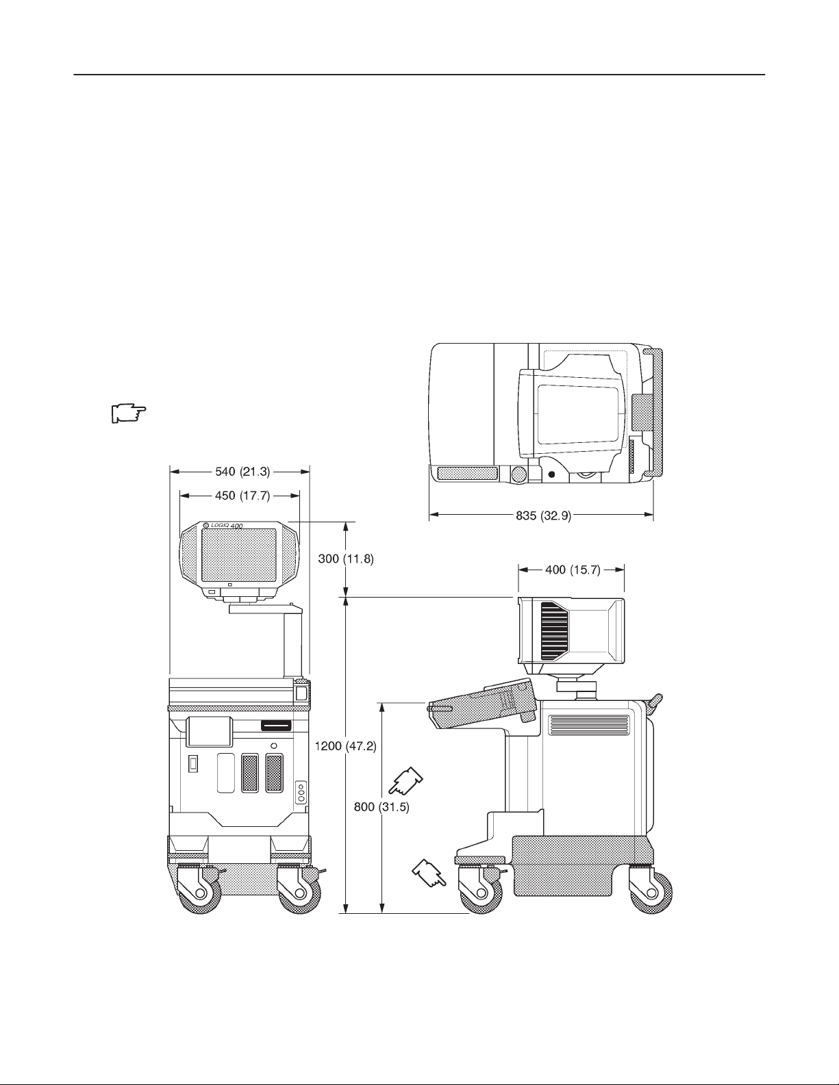
GE MEDICAL SYSTEMS
REV 9
LOGIQ 400 SERVICE MANUAL
2127661
3–1 INTRODUCTION
This chapter describes system configuration and specifications.
3–2 DIMENSIONS
Regarding LOGIQ 400 dimensions, Refer to ILLUSTRATION 3–1 and 3–2, for planning the position of your
LOGIQ 400.
WEIGHT: 145 kg
320 lbs
NOTE
LENGTH : mm (inches)
ABERRATION : ±10%
OVERALL DIMENSIONS (Color Monitor Models and B/W Monitor Models with S/W V4.01 or later)
ILLUSTRATION 3–1
3–3
SYSTEM CONFIGURA TION
Page 52

GE MEDICAL SYSTEMS
REV 9
3–2 DIMENSIONS (continued)
WEIGHT: 136 kg
300 lbs
NOTE
LENGTH : mm (inches)
ABERRATION : ±10%
LOGIQ 400 SERVICE MANUAL
2127661
OVERALL DIMENSIONS (B/W Monitor Models with S/W V3.40 or earlier)
ILLUSTRATION 3–2
Note
The ILLUSTRA TION 3–2 shows the dimensions for the B/W console with the software version 3.40 or
earlier. For the dimensions of the B/W console with the software version 4.01 or later, refer to
ILLUSTRATION 3–1.
3–4
SYSTEM CONFIGURA TION
Page 53

GE MEDICAL SYSTEMS
REV 9
LOGIQ 400 SERVICE MANUAL
2127661
3–2 DIMENSIONS (continued)
ILLUSTRATION 3–3 shows the dimensions for the LOGIQ 400 console with the software version 5.01y or later.
Note
The tall type console is 75mm taller than the normal height console.
WEIGHT: 145 kg
320 lbs
NOTE
LENGTH : mm (inches)
ABERRATION : ±10%
OVERALL DIMENSIONS (15–INCH Monitor Models with S/W V5.01 or later)
ILLUSTRATION 3–3
3–5
SYSTEM CONFIGURA TION
Page 54

GE MEDICAL SYSTEMS
REV 9
LOGIQ 400 SERVICE MANUAL
2127661
3–3 ELECTRICAL SPECIFICA TIONS
Electrical conduit, junction boxes, outlets, circuit breakers, and switches should be in place before installing the
LOGIQ 400 console.
3–3–1 Power Supply
Voltage setup is performed in the factory, since different rear panels which contain different power cables and circuit
breakers are used for the 100 VAC and 220 VAC versions.
3–3–2 Facility Power Receptacle
A separate power outlet with a 15 amp circuit breaker for 1 15 VAC units, or a 7.5 amp circuit breaker for 220 V AC units,
is recommended. The specific power receptacle used depends on your country’s power line standards.
The receptacle should have International Electrotechnical Commission (IEC) approval, or equivalent.
3–4 STORAGE AND OPERATION REQUIREMENTS
The LOGIQ 400 is shipped in a single container excluding PROBES. Shipping weight is approximately 395 lbs
(179kg) [B/W monitor console: 375lbs (170kg)]. The size of the container is D1 100 mm x W660 mm x H1390 mm. (43
in. x 26 in. x 55 in). T ABLE 3–1 provides a summary of temperature, atmospheric pressure, and humidity tolerances
for shipping, installation, and operation:
TABLE 3–1
STORAGE AND OPERATION REQUIREMENTS
PARAMETER STORAGE OPERATION
TEMPERATURE (DEG.C)
(DEG.F)
ATOMOSPHERIC PRESSURE
(hPa)
HUMIDITY (%)
(Non–condensing)
–10 to 60
14 to 140
700 to 1060 700 to 1060
30 to 95 30 to 85
10 to 40
50 to 104
3–6
SYSTEM CONFIGURA TION
Page 55

GE MEDICAL SYSTEMS
REV 9
LOGIQ 400 SERVICE MANUAL
2127661
3–5 OPTIONAL PERIPHERALS
3–5–1 Peripherals/Accessories Connector Panel
LOGIQ 400 peripherals and accessories can be properly connected using the rear connector panel located behind
the rear door.
The serial ports for controlling recording devices, video input/output connectors, audio input/output connectors, camera expose connectors, foot switch connector, and power outlet connectors for peripherals are located on the rear
panel.
This section indicates the pin assignment for each connector (
3–8.
1–6
in ILLUSTRA TION 3–4) at pages 3–7 through
REAR CONNECTOR PANEL
ILLUSTRATION 3–4
Note
The B/W console with the software version 4.01 or later has the same Rear Connector Panel,
3–7
SYSTEM CONFIGURA TION
Page 56

GE MEDICAL SYSTEMS
REV 9
3–5–1 Peripherals/Accessories Connector Panel (Continued)
Note
The Ethernet Port (
with the software version 3.40 or later and the optional DICOM Upgrade Set.
Each outer (case) ground line of peripheral/accessory connectors are protectively grounded.
Signal ground lines are Not Isolated, except the Service port (1). All of signal lines (include signal
GND) of the Service port are isolated.
6
in ILLUSTRA TION 3–4) for the DICOM connection is available on the console
Note
LOGIQ 400 SERVICE MANUAL
2127661
Output level of RS232C signals:
Note
High +3V to +15V
Low –15V to 0V
3–8
SYSTEM CONFIGURA TION
Page 57

GE MEDICAL SYSTEMS
REV 9
3–5–1 Peripherals/Accessories Connector Panel (Continued)
LOGIQ 400 SERVICE MANUAL
2127661
Note
Output level of control signals indicated in the above tables are TTL level.
3–9
SYSTEM CONFIGURA TION
Page 58

GE MEDICAL SYSTEMS
REV 9
3–5–1 Peripherals/Accessories Connector Panel (continued)
Ethernet
RN
+12V
Note
Output level of RS232C signals:
High +3V to +15V
Low –15V to 0V
LOGIQ 400 SERVICE MANUAL
2127661
3–10
SYSTEM CONFIGURA TION
Page 59

GE MEDICAL SYSTEMS
REV 9
LOGIQ 400 SERVICE MANUAL
2127661
3–5–2 List of Optional Peripherals
The tables below show the optional connectable peripherals for LOGIQ 400. Proper remote control and image recording when connecting these peripherals to LOGIQ 400, are verified.
1. RECORDING DEVICES
TABLE 3–2
LIST OF RECORDING DEVICES
DEVICE MANUFACTURER MODEL VIDEO SIGNAL
Video Cassette Recorder SONY SVO–9500MD NTSC
SONY SVO–9500MDP PAL
Color Video Printer SONY UP–1850MD NTSC
SONY UP–1850EPM PAL
SONY UP–2950MD NTSC
SONY UP–2850P P AL
SONY UP–2900MD NTSC
SONY UP–2800P P AL
Video Graphic Printer SONY UP890MD NTSC
SONY UP890CE PAL
SONY UP890MDG NTSC/PAL
Note
If the customer need to connect the other peripherals with LOGIQ 400 console, please contact the
address shown in Chapter 1 of this manual.
Note
The “Quaf–Frm” format is available only for the following color printers:
UP–1850MD, UP–1850EPM, UP–2950MD, and UP–2850P
The “Quaf–Frmls” selection for the Color Printer Memory in the SYSTEM PARAMETER SETUP, is
not available for those printers. This function is valid only for the UP–3030MD printer.
3–1 1
SYSTEM CONFIGURA TION
Page 60

GE MEDICAL SYSTEMS
LOGIQ 400 SERVICE MANUAL
REV 9
3–5–2 List of Optional Peripherals (Continued)
2. CONNECTING CABLES
CAUTION
Equipment damage possibility . Be sure to use the following recommended connecting cables
to connect recording devices with LOGIQ 400 console.
TABLE 3–3
LIST OF CONNECTING CABLES
NAME PART NO. FIGURE NOTE
POWER CABLE P9509EE For recording device
P9509LH Used only for installing B/W Video
Printer on front of console
RS232C CABLE P9509MN For control signals
2127661
2150410 For Insite connection
MINI PLUG CABLE P9509BE For control signals (used only
for B/W Video Printer)
Ethernet Cable 2195662 For DICOM capability
Included in the DICOM Support
option with Tranceivers
3–12
SYSTEM CONFIGURA TION
Page 61

GE MEDICAL SYSTEMS
REV 9
3–5–2 List of Optional Peripherals (Continued)
3. PROBES
LIST OF TRANSDUCERS
TABLE 3–4
LOGIQ 400 SERVICE MANUAL
2127661
PROBE MATERIAL OF AREA OF CATALOG REQUIRED
NAME HEADSHELL USING NO. ADAPTER
C364 PES ABDOMINAL CONVEX H45202CF
C551 PES ABDOMINAL CONVEX H45202CE
E721 PES INTRACAVITY CONVEX H45202MT
C721 NORYL NEONATAL CONVEX H45202MN No need
739L NORYL SUPERFICIAL LINEAR H45202AG
L764 PES SUPERFICIAL LINEAR H45202HP
S220 PES CARDIAC SECTOR H45202WG
CBF PES ABDOMINAL CONVEX H46022CB
CAE PES ABDOMINAL CONVEX H46022CA
MTZ PES INTRACA VITY CONVEX H46022MT
LH PES SUPERFICIAL LINEAR H46022LH
W PES CARDIAC SECTOR H4162C 5S
546L NORYL LINEAR H45202LE
S317 NORYL CARDIAC/ABDOMINAL SECTOR H45202SD
S611 NORYL SECTOR H45202SF
C386 NORYL CONVEX H45202CC No need
I739 NORYL LINEAR H45202JG
T739 NORYL INTRAOPERA TIVE LINEAR H45202TG
LA39 NORYL SUPERFICIAL LINEAR H45202LA
B510 PU CARDIAC H45202BT PA51
S222 NORYL TRANSCRANIAL SECTOR H45202TC
CWD2 NOR YL CARDIAC CWD H45202DB No need
CWD5 NOR YL CARDICAC CWD H45202DE
ABDOMINAL/
SUPERFICIAL
CARDIAC/NEONATAL/
PEDIATRICS
ABDOMINAL/
OB/GYN
INTRAOPERATIVE/
INTRACAVITY
TYPE FAMILY PROBES PART No.
PA51
BI–PLANE
SECTOR
HEAD SHELL IS
SAME AS CBF
HEAD SHELL IS
SAME AS CAE
HEAD SHELL IS
SAME AS MTZ
HEAD SHELL IS
SAME AS LH
HEAD SHELL IS
SAME AS W
HEAD SHELL IS
SAME AS 739L
P9607AB
P9607AA
P9607AD
P9607AC
P9607AF
P9607AE
2121267–2
2121267
2107460–2
2107460
2121377–2
2121377
2121793–2
2121793
P9603AD
P9603AA
P9603AE
P9603AB
P9603AU
P9603AL
P9601AS
P9601AC
P9600BH
P9600BD
2144266–2
2144266
2144268–2
2144268
2144267–2
2144267
2154186–2
2154186
2147189–2
2147189
2147188–2
2147188
2155078–2
2155078
2123593
21331 15
2159263
2156263
2123594
21331 16
2123595
21331 17
3–13
SYSTEM CONFIGURA TION
Page 62

GE MEDICAL SYSTEMS
REV 9
3–5–2 List of Optional Peripherals (continued)
3. PROBES (Continued)
LIST OF TRANSDUCERS (continued)
TABLE 3–5
LOGIQ 400 SERVICE MANUAL
2127661
PROBE MATERIAL OF AREA OF CATALOG REQUIRED
NAME HEADSHELL USING NO. ADAPTER
LD PES BIOPSY LINEAR PA 51
C358 PES ABDOMINAL CONVEX H45202CD
ERB7 NORYL ENDOCAVITY H40392LC
3S NORYL CARDIOLOGY SECTOR H4550SZ No Needed
TYPE FAMILY PROBES PART No.
LINEAR/
CONVEX
Note
PES : Polyethersulfone NORYL : Modified Polyphenylene Oxide PU : Polyurethane
Note
Some probes listed on the table above have two different part numbers. The number of upper row
indicates the part number of probes for the region other than Japan. The number of lower row indicates the part number of probes for Japan.
Probes which have only one part number are not available in Japan.
Note
546L, S317, S61 1, C386, I739, T739 and LA39 probes are available on LOGIQ 400 console from
software version 3.00.
P9601AD
2193617
2172443
2239590
2204232
2252157
Note
B510, S222, CWD2 and CWD5 probes are available on LOGIQ 400 console from software version
3.10.
Note
The following probes are not available on LOGIQ 400CL:
S220, B510, CWD2, CWD5, S317, S611, and S222
Note
The LD probe is available only for the Japanese console with the software version 3.40 or later.
Note
The C358 and ERB7 probes are available on LOGIQ 400 console with the software version 4.01 or
later.
Note
The 3S probe is available on LOGIQ 400 console with the software version 5.01 or later.
3–14
SYSTEM CONFIGURA TION
Page 63

GE MEDICAL SYSTEMS
LOGIQ 400 SERVICE MANUAL
REV 9
3–5–3 Power Consumption of Optional Peripherals
The table below shows the power consumption of each optional peripheral for LOGIQ 400.
TABLE 3–6
POWER CONSUMPTION OF OPTIONAL RECORDING DEVICES
DEVICE MODEL POWER CONSUMPTION
Video Cassette Recorder SVO–9500MD 64W
SVO–9500MDP
Color Video Printer UP–1850MD 140W
UP–1850EPM
UP–2950MD 220W
UP–2850P (at printing)
UP–2900MD 180W
UP–2800P (at printing)
B/W Video Printer UP890MD 110W
UP890CE
UP890MDG 120W
(at printing)
2127661
3–15
SYSTEM CONFIGURA TION
Page 64

GE MEDICAL SYSTEMS
LOGIQ 400 SERVICE MANUAL
REV 9
3–6 VIDEO SPECIFICA TIONS
TABLE 3–7
VIDEO SPECIFICATIONS
12–inch monitor 15–inch monitor
NTSC PAL NTSC PAL
Total Line per Frame [Line] 525 625 525 625
Vertical Frame Frequency [Hz] 30 25 60 50
Horizontal Scanning Frequency [kHz] 15.734 15.625 31.469 31.250
Displayed Image Pixels [mm] 207.0 by
157.3
Total Horizontal Line Time [s]
Horizontal Display [s]
Front Porch Width [s]
Sync Pulse Width [s]
Back Porch Width [s]
Total Horizontal Blanking [s]
63.56 64.00 31.78 32.00
49.54 48.81 24.77 24.41
2.76 3.09 1.39 1.54
4.73 4.68 2.36 2.34
6.53 7.42 3.26 3.71
14.02 15.19 7.01 7.59
207.0 by
157.3
239.5 by
180
Vertical Blanking Interval [H] 31.50 38.50 31.50 38.50
Vertical Front Porch Width [H] 6.5 9.0 6.5 9.0
Vertical Sync W idth [H] 3 2.5 3 2.5
Vertical Back Porch W idth [H] 22 27 22 27
Pixel Clock [MHZ] 12.2727 14.7500 24.5454 29.5000
H[s]
63.56 64 31.78 32
2127661
239.5 by
180
3–16
SYSTEM CONFIGURA TION
Page 65

GE MEDICAL SYSTEMS
REV 6
LOGIQ 400 SERVICE MANUAL
2127661
CHAPTER 4 – FUNCTIONAL CHECKS
TABLE OF CONTENTS
SECTION TITLE PAGE
4–1 INTRODUCTION 4–3. . . . . . . . . . . . . . . . . . . . . . . . . . . . . . . . . . . . . . . . . . . . . . . . . . . . . . . . . . . . . . . . . . . . .
4–1–1 Required Equipment 4–3. . . . . . . . . . . . . . . . . . . . . . . . . . . . . . . . . . . . . . . . . . . . . . . . . . . . . . . . . .
4–2 FUNCTIONAL CHECK PROCEDURES 4–4. . . . . . . . . . . . . . . . . . . . . . . . . . . . . . . . . . . . . . . . . . . . . . . . .
4–2–1 Basic Controls 4–4. . . . . . . . . . . . . . . . . . . . . . . . . . . . . . . . . . . . . . . . . . . . . . . . . . . . . . . . . . . . . . .
4–3 DIAGNOSTICS 4–10. . . . . . . . . . . . . . . . . . . . . . . . . . . . . . . . . . . . . . . . . . . . . . . . . . . . . . . . . . . . . . . . . . . . . .
4–3–1 Service Software Menu 4–10. . . . . . . . . . . . . . . . . . . . . . . . . . . . . . . . . . . . . . . . . . . . . . . . . . . . . .
4–3–2 Diagnosis Test Menu 4–11. . . . . . . . . . . . . . . . . . . . . . . . . . . . . . . . . . . . . . . . . . . . . . . . . . . . . . . .
4–3–3 Utility Menu 4–16. . . . . . . . . . . . . . . . . . . . . . . . . . . . . . . . . . . . . . . . . . . . . . . . . . . . . . . . . . . . . . . .
4–4 POWER SUPPLY ADJUSTMENTS 4–37. . . . . . . . . . . . . . . . . . . . . . . . . . . . . . . . . . . . . . . . . . . . . . . . . . . .
4–4–1 Power Supply Access 4–38. . . . . . . . . . . . . . . . . . . . . . . . . . . . . . . . . . . . . . . . . . . . . . . . . . . . . . .
4–4–2 Power Supply Adjustment Procedure 4–40. . . . . . . . . . . . . . . . . . . . . . . . . . . . . . . . . . . . . . . . . .
4–1
FUNCTIONAL CHECKS
Page 66

GE MEDICAL SYSTEMS
REV 0
This page is left blank intentionally.
LOGIQ 400 SERVICE MANUAL
2127661
4–2
FUNCTIONAL CHECKS
Page 67

GE MEDICAL SYSTEMS
REV 2
4–1 INTRODUCTION
This chapter provides procedures for quickly checking major functions of the LOGIQ 400 console, diagnostics by
using the built–in service software, and power supply adjustments.
4–1–1 Required Equipment
To perform these tests, you’ll need any of a sector , linear, or a convex transducer.
Note
The soft menu displayed on the CRT monitor screen disappears automatically by the time set with the
CRT Menu Auto Erase Interval of the System Parameter (page 1/6). When the “Inf” is selected, the
soft menu does not disappear automatically.
LOGIQ 400 SERVICE MANUAL
2127661
4–3
FUNCTIONAL CHECKS
Page 68

GE MEDICAL SYSTEMS
REV 1
4–2 FUNCTIONAL CHECK PROCEDURES
4–2–1 Basic Controls
Step Check Expected result
1. Connect a sector or convex
transducer to ”Probe 2”
connector beneath keyboard.
2. Turn ON Power toggle switch.
3. Type USER ID and then press PATIENT ENTRY MENU should appear.
return key as necessary.
4. Press New Patient key. After a few seconds, the B mode screen should appear
5. Press Top Menu Select key The top menu should appear on the CRT monitor screen
twice. as follows:
LOGIQ 400 SERVICE MANUAL
as shown in ILLUSTRATION 4–1.
2127661
Note
The items displayed on the T op Menu are different depending on the component options.
6. Select B section using or The B selection is displayed in reverse video.
key.
7. Press key. The B mode sub-menu should appear on CRT monitor
screen as follows:
8. Select Dynamic Range section The Dynamic Range selection is displayed in reverse
using or key. video.
9. Change Dynamic Range up/ Image grows softer and harder depending on position.
down using or key.
10. Press Top Menu Select key The menus on CRT monitor screen should disappear.
twice.
11. Rotate B/M Gain knob. Image grows lighter and darker with rotation.
12. Slide TGC potentiometers Image grows darker or brighter at depth equivalent to
(pots). pot’s location.
13. Rotate Depth knob. The depth of image should be magnified/reduced.
14. Press Reverse key. The image reverses the left/right orientation.
15. Press Reverse key again. The image reverses the left/right orientation.
4–4
FUNCTIONAL CHECKS
Page 69

GE MEDICAL SYSTEMS
REV 0
4–2–1 Basic Controls (Continued)
LOGIQ 400 SERVICE MANUAL
2127661
B–MODE DISPLAY SCREEN
ILLUSTRATION 4–1
4–5
FUNCTIONAL CHECKS
Page 70

GE MEDICAL SYSTEMS
REV 1
4–2–1 Basic Controls (Continued)
Step Check Expected result
16. Press M key. The M mode timeline should appear below the B image
17. Roll trackball. The M mode cursor should follow trackball movement and
18. Press Scan Area key. The indicator LED located at the left side of the Scan Area
19. Roll trackball. The width of B mode image should change wider or
20. Press M/D Cursor key. The indicator LED located at the left side of the M Cursor
21. Press Top Menu Select key The top menu should appear on the CRT monitor screen
twice. as follows:
LOGIQ 400 SERVICE MANUAL
as shown in ILLUSTRATION 4–2. Whether it takes half
the screen or two–thirds depends on the preset.
the timeline should update for new location of focus.
key should be ON and the color of the M mode cursor
should change.
narrower.
key should be ON and the M mode cursor should become
active again.
2127661
Note
The items displayed on the T op Menu are different depending on the component options.
22. Select M section using or The M selection is displayed in reverse video.
key.
23. Press key. The M mode sub-menu should appear on CRT monitor
screen as follows:
24. Select Edge Enhance section The Edge Enhance selection is displayed in reverse video.
using or key.
25. Change M Edge Enhance up/ Changes the M–Mode image.
down using or key.
26. Press Top Menu Select key The menus on CRT monitor screen should disappear.
twice.
4–6
FUNCTIONAL CHECKS
Page 71

GE MEDICAL SYSTEMS
REV 0
4–2–1 Basic Controls (Continued)
LOGIQ 400 SERVICE MANUAL
2127661
M–MODE DISPLAY SCREEN
ILLUSTRATION 4–2
Note
You can select the two types of display format: Side by Side (with the 2–D display to the left of the
M–mode display) and Top/Bottom (with the 2–D display on top of the M–mode display) by using the
Preset Menu. For the Preset Menu, refer to Customizing Y our System in the LOGIQ 400 User Man–
ual.
4–7
FUNCTIONAL CHECKS
Page 72

GE MEDICAL SYSTEMS
REV 1
4–2–1 Basic Controls (Continued)
Step Check Expected result
27. Press B key. The B mode screen should appear as shown in
28. Press CFM key. The CFM mode screen should appear as shown in
29. Rotate Gain knob Color image noise should appear.
30. Press Freeze key. The image should freeze.
31. Rotate Cine Scroll knob. The Cine gauge should appear under the B mode image.
32. Press Freeze key again. The image revives acquisition and the Cine gauge should
33. Press CFM key again. The B mode screen should appear as shown in
ILLUSTRATION 4–1.
ILLUSTRATION 4–3.
disappear.
ILLUSTRATION 4–1.
LOGIQ 400 SERVICE MANUAL
2127661
CFM MODE DISPLAY SCREEN
ILLUSTRATION 4–3
Note
Y ou can select the four types of CFM window: Survey, Survey Detail, Map, and Map Detail by using
the CUSTOM DISPLA Y Preset Menu. For the CUSTOM DISPLA Y Preset Menu, refer to Customizing
Your System in the LOGIQ 400 User Manual.
4–8
FUNCTIONAL CHECKS
Page 73
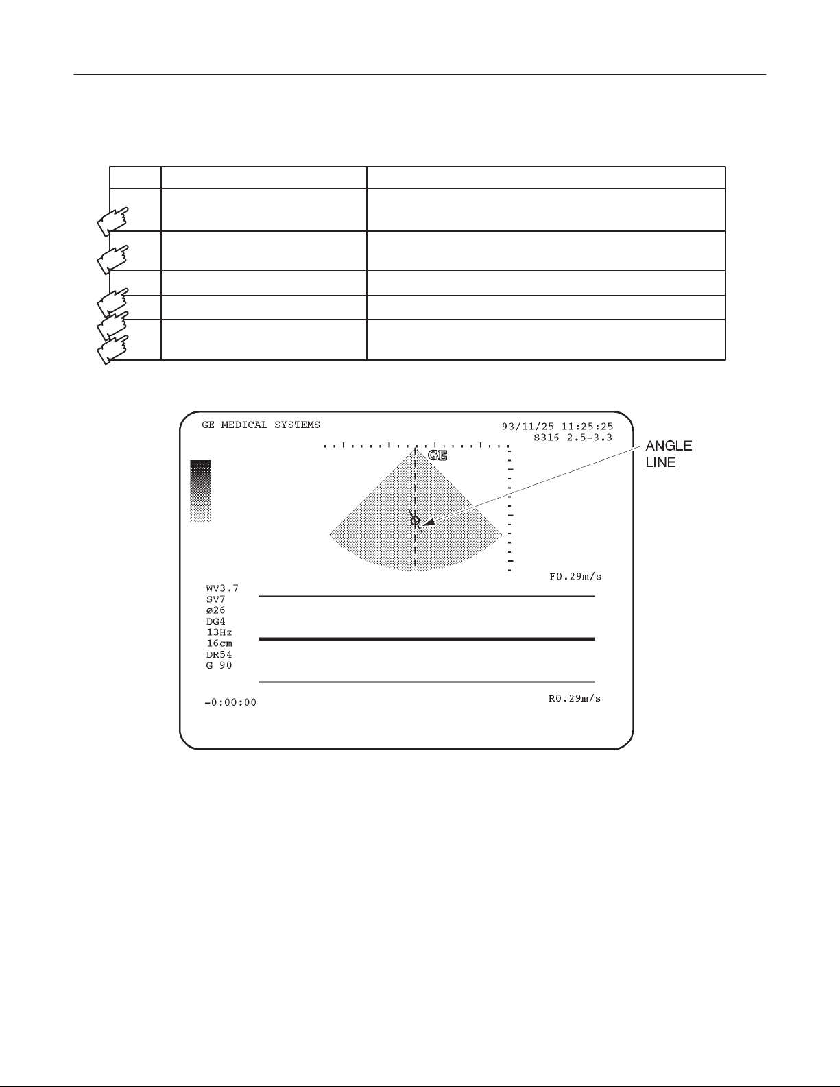
GE MEDICAL SYSTEMS
REV 1
4–2–1 Basic Controls (Continued)
Step Check Expected result
34. Press PD key. The Pulse Doppler mode screen should appear as shown
in ILLUSTRA TION 4–4.
LOGIQ 400 SERVICE MANUAL
2127661
35. Rotate
θ Angle knob. A line should appear in the circle on the B mode image
and that line displayed with circle should rotate.
36. Rotate Gain knob. The Doppler noise should increase/decrease.
37. Rotate Audio Volume knob. The Doppler audio volume should increase/decrease.
38. Press B key. The B mode screen should appear as shown in
ILLUSTRATION 4–1.
PULSE DOPPLER MODE DISPLAY SCREEN
ILLUSTRATION 4–4
Note
You can select the two types of display format: Side by Side (with the 2–D display to the left of the
PD–mode display) and T op/Bottom (with the 2–D display on top of the PD–mode display) by using the
Preset Menu. For the Preset Menu, refer to Customizing Y our System in the LOGIQ400 User Man–
ual.
4–9
FUNCTIONAL CHECKS
Page 74

GE MEDICAL SYSTEMS
REV 1
4–3 DIAGNOSTICS
4–3–1 Service Software Menu
1. Press the Top Menu Select key located on the keyboard twice.
SOFTWARE MENU CONTROL KEYS
ILLUSTRATION 4–5
LOGIQ 400 SERVICE MANUAL
2127661
The top menu is displayed on CRT monitor screen as shown in ILLUSTRATION 4–6.
TOP MENU
ILLUSTRATION 4–6
Note
The items displayed on the Top Menu are different depending on the component options.
2. Select the Set Up Menu using the or key of Sub Menu Select keys on the keyboard. The Set Up selection is displayed in reverse video as shown in ILLUSTRATION 4–6.
3. Press key to select the Set Up Menu. The Set Up Menu is displayed on the CRT monitor screen as shown in
ILLUSTRATION 4–7.
SET UP MENU
ILLUSTRATION 4–7
4. Select the Diag. section using the or key and press key to use the User Diagnostics function. The
Diagnosis Menu is displayed on the CRT monitor screen. Refer to ILLUSTRA TION 4–8. Select the Utility section
using the
or key and press key to use User Utility function. The Utility Menu is displayed on the
CRT monitor screen. Refer to ILLUSTRATION 4–13.
4–10
FUNCTIONAL CHECKS
Page 75

GE MEDICAL SYSTEMS
REV 0
LOGIQ 400 SERVICE MANUAL
2127661
4–3–2 Diagnosis Test Menu
Select the Diag. section using the or key and press key to use the User Diagnostics function. The
Diagnosis Menu is displayed on the CRT monitor screen as shown in ILLUSTRATION 4–8.
DIAGNOSIS TEST MENU
ILLUSTRATION 4–8
Note
Press and hold the Control key and press R to display the previous menu in the User Diagnostics
mode.
4–1 1
FUNCTIONAL CHECKS
Page 76

GE MEDICAL SYSTEMS
LOGIQ 400 SERVICE MANUAL
REV 0
4–3–2 Diagnosis Test Menu (Continued)
(A) SYSTEM TEST 1
Make sure that one or more probes are connected with console before executing the following system test.
Type 1 and then press the Return key when the Diagnosis Test Menu is displayed. The system test will start
automatically . After checking each test item, ”Passed” or ”Failed” is displayed depending on the actual test result.
2127661
SYSTEM TEST 1
ILLUSTRATION 4–9
The system beeps three times after checking all the tests.
If system does not pass the diagnostic test, please contact the qualified service engineer in your area. Please
refer to Chapter 1 of this manual for the appropriate address/phone number to contact service.
4–12
FUNCTIONAL CHECKS
Page 77

GE MEDICAL SYSTEMS
LOGIQ 400 SERVICE MANUAL
REV 0
4–3–2 Diagnosis Test Menu (Continued)
(B) TEST PATTERN BLACK & WHITE
The black & white pattern permits the serviceman to accurately adjust the contrast of an optional equipment
(such as a camera) to see the details in the lightest and darkest areas of the image.
Type 2 and then press Enter key when the Diagnosis Menu is displayed. The T est Pattern Black & White is dis-
played as shown in ILLUSTRATION 4–10.
2127661
TEST PATTERN BLACK & WHITE
ILLUSTRATION 4–10
4–13
FUNCTIONAL CHECKS
Page 78

GE MEDICAL SYSTEMS
LOGIQ 400 SERVICE MANUAL
REV 1
4–3–2 Diagnosis Test Menu (Continued)
(C) TEST PATTERN COLOR
The color scale permits the serviceman to adjust the color contrast of an optional equipment (such as a color
video printer).
Type 3 and then press Enter key when the Diagnosis Menu is displayed. The T est Pattern Color is displayed as
shown in ILLUSTRATION 4–11.
2127661
TEST PATTERN COLOR
ILLUSTRATION 4–11
Note
In case of B/W monitor system, this function is invalid. The message ”Not tested” is displayed on the
CRT monitor screen when the option number 3, Test Pattern Color is selected.
4–14
FUNCTIONAL CHECKS
Page 79

GE MEDICAL SYSTEMS
LOGIQ 400 SERVICE MANUAL
REV 0
4–3–2 Diagnosis Test Menu (Continued)
(D) TEST PATTERN GRAPHICS
The vertical linearity and graphics perimeter pattern should be centered on the optional equipment display . This
ensures all whitescale graphics overlays will be visible.
Type 4 and then press Enter key when the Diagnosis Menu is displayed. The T est Pattern Graphics is displayed
as shown in ILLUSTRATION 4–12.
2127661
TEST PATTERN GRAPHICS
ILLUSTRATION 4–12
4–15
FUNCTIONAL CHECKS
Page 80

GE MEDICAL SYSTEMS
REV 6
LOGIQ 400 SERVICE MANUAL
2127661
4–3–3 Utility Menu
Select the Utility section using the or key and press key to use the User Utility function. The Utility
Menu is displayed on the CRT monitor screen as shown in ILLUSTRATION 4–13.
UTILITY MENU
ILLUSTRATION 4–13
Note
Press and hold the Control key and press R to display the previous screen in the User Utility mode.
Note
Item 12 (for V4.01, V4.02 or later) and item 1 1 (for V3.40 or V3.41), Network Error Log Display is the
additional function for the console with the software version 3.40 or later. This menu is displayed and
available only when the Storage/Print DICOM option is enabled.
Note
Item 11, Monitor Adjustment is available on the console with the software version 4.01 or later.
4–16
FUNCTIONAL CHECKS
Page 81

GE MEDICAL SYSTEMS
LOGIQ 400 SERVICE MANUAL
REV 0
4–3–3 Utility Menu (Continued)
(A) TIME ADJUSTMENT
This changes the current time in the system.
Type 1 and then press Enter key when the Utility Menu is displayed. The system date and time previously set is
displayed as shown in ILLUSTRATION 4–14.
2127661
TIME ADJUSTMENT SCREEN
ILLUSTRATION 4–14
Procedure
1. Input the time difference using the numeric keys on keyboard and then press <Enter>. The input format for the
time is ”HH:MM”. You can change the current time within ±12 hours
Note
Put a ”–” character in front of the time difference to decrease the current time.
After changing the current time, the Utility Menu reappears on the CRT monitor.
4–17
FUNCTIONAL CHECKS
Page 82

GE MEDICAL SYSTEMS
LOGIQ 400 SERVICE MANUAL
REV 5
4–3–3 Utility Menu (Continued)
(B) ERROR LOG DISPLAY
This loads and displays an error log file, or saves it into the MO (Magneto Optical) disk.
Type 2 and then press Return key when the Utility Menu is displayed. The Error Log Display is displayed as
shown in ILLUSTRATION 4–15.
2127661
ERROR LOG FILE DISPLAY
ILLUSTRATION 4–15
Procedure for Saving File
1. Type Y and then press Return key.
2. Insert an 128MB MO (Magneto Optical) disk (or 230MB disk for the conosle with software version 3.10 or later)
into the MOD drive of console and press any key.
Note
Use new initialized MO disk. It is impossible to save the error log file into the disk which another file is
already stored.
Note
The 230MB MO disk is available on the console with software version 3.10 or later.
During the time that the system is saving the error log file, “Copying now” is displayed on the CRT monitor.
4–18
FUNCTIONAL CHECKS
Page 83

GE MEDICAL SYSTEMS
LOGIQ 400 SERVICE MANUAL
REV 1
4–3–3 Utility Menu (Continued)
(C) TROUBLE IMAGE SAVE/LOAD/DISPLAY
This saves the trouble image recorded in the Hard Disk into the MO (Magneto Optical) Disk. This also loads the
image data saved in the MO Disk into the Hard Disk and displays the trouble image selected on the CRT monitor
by using the image recall function.
Note
Press and hold the Control key and press W to save the trouble image into the hard disk. You can
save the maximum 8 images into the hard disk.
Note
T o save the trouble image into the hard disk, the optional VIPB Assy must be installed on the console
instead of VIDO Assy . Otherwise, the message ”This function is not available.” will be displayed on the
CRT monitor screen.
Type 3 and then press Return key when the Utility Menu is displayed. The following screen is displayed.
2127661
TROUBLE IMAGE SAVE/LOAD/DISPLAY (a)
ILLUSTRATION 4–16
4–19
FUNCTIONAL CHECKS
Page 84

GE MEDICAL SYSTEMS
REV 5
4–3–3 Utility Menu (Continued)
(C) TROUBLE IMAGE RECORD & DISPLAY (Continued)
Procedure for Saving Trouble Images
1. Type 1 and then press Return key . The message “Set a media to drive and then press any key .” is displayed.
2. Set an 128MB MO (Magneto Optical) disk (or 230MB disk for the conosle with software version 3.10 or later)
into the MOD drive and press any key. The Trouble Image File Menu will be displayed on the CRT monitor
screen. Refer to ILLUSTRATION 4–16.
Note
Use new initialized MO disk. It is impossible to save any trouble image files into the disk which another
file is already stored.
Note
The 230MB MO disk is available on the console with software version 3.10 or later.
LOGIQ 400 SERVICE MANUAL
2127661
3. Input the file number you desire to save into the MO disk.
4. Press Return key.
During the system is saving the file, “Saving now” is displayed on the CRT monitor . After saving the file, “Suc–
ceeded” or “Failed” is displayed on the CRT monitor. Then, the message “Press Y to continue, Control + R to
quit” is displayed. Type Y and press Return to continue to use this function. Press and hold the Control key, and
press R to quit this function.
Procedure for Loading Trouble Images
1. Type 2 and then press Return key . The message “Set a media to drive and then press any key .” is displayed.
2. Set an 128MB MO (Magneto Optical) disk (or 230MB disk for the conosle with software version 3.10 or later)
into the MOD drive and press any key. The Trouble Image File Menu will be displayed on the CRT monitor
screen. Refer to ILLUSTRATION 4–16.
Note
The 230MB MO disk is available on the console with software version 3.10 or later.
3. Input the file number you desire to load from the MO disk.
4. Press Return key.
During the system is loading the file, “Loading now” is displayed on the CRT monitor. After saving the file, “Suc–
ceeded” or “Failed” is displayed on the CRT monitor. Then, the message “Press Y to continue, Control + R to
quit” is displayed. Type Y and press Return to continue to use this function. Press and hold the Control key, and
press R to quit this function.
4–20
FUNCTIONAL CHECKS
Page 85

GE MEDICAL SYSTEMS
REV 5
4–3–3 Utility Menu (Continued)
(C) TROUBLE IMAGE RECORD & DISPLAY (Continued)
Procedure for Displaying Trouble Images
1. Type 3 and then press Return key . The Trouble Image File Menu will be displayed on the CRT monitor screen.
Refer to ILLUSTRATION 4–16.
2. Input the file number you desire to display on the CRT monitor screen.
3. Press Return key.
Press and hold the Control key and press Q to display the Trouble Image Menu on the CRT monitor screen.
LOGIQ 400 SERVICE MANUAL
2127661
4–21
FUNCTIONAL CHECKS
Page 86

GE MEDICAL SYSTEMS
REV 5
4–3–3 Utility Menu (Continued)
(D) USER DATA BACK UP
This saves the user preset data into the MO disk. This also loads the user preset data stored in the MO disk.System Parameter, Probe Parameter, and the User Table into the external recording media.
Note
The user preset data is different depending on each category.
You can select the user preset data from among the following menu.
1. System Data
2. Application (Rad/Abdomen) Data
3. Application (Obstetrics) Data
4. Application (Gynecology) Data
5. Application (Cardiology) Data
6. Application (Vascular) Data
7. Application (Ulorogy) Data
8. Application (Small Parts) Data
9. All System & Application Data
LOGIQ 400 SERVICE MANUAL
2127661
System data includes:
System Preset Data File, User Define Data File*, VCR Registration Information
Data File*, VCR Patient Information Data File*, and Image Archive Search Data
File*
Each application data includes:
Application Preset Data File, Probe Preset Data File, Report Format Data File,
OB Table Data File, Fetal Trend Patient Data File*, and Cardiac Calc. Auto Sequence Data File*
The files with the symbol “*” listed above are saved only when the software options are installed and
any files are stored in the hard disk.
Note
The 230MB MO disk is available on the console with software version 3.10 or later.
4–22
FUNCTIONAL CHECKS
Page 87

GE MEDICAL SYSTEMS
LOGIQ 400 SERVICE MANUAL
REV 5
4–3–3 Utility Menu (Continued)
(D) USER DATA BACK UP (Continued)
Type 4 and then press Return key when the Utility Menu is displayed. The User Data Back Up Menu is displayed
as shown in ILLUSTRATION 4–17.
USER DATA BACK UP MENU
ILLUSTRATION 4–17
2127661
Note
Y ou cannot save two or more items into one MO disk. If you want to save two or more items of the User
Data Menu into one MO disk, Choose the item 09, All System & Application Data.
Procedure for Saving User Data
1. Type 1 and then press the Return key. The message “Set a media to drive and then press any key” is dis-
played.
2. Insert an initialized 128MB MO (Magneto Optical) disk (or 230MB disk for the conosle with software version
3.10 or later) into the MOD drive of console and press the Return key . The User Data Menu is displayed on the
CRT monitor screen as shown in ILLUSTRATION 4–18.
Note
Use new initialized MO disk. It is impossible to save any user data files into the disk which another file
is already stored.
USER DATA MENU
ILLUSTRATION 4–18
4–23
FUNCTIONAL CHECKS
Page 88

GE MEDICAL SYSTEMS
REV 5
4–3–3 Utility Menu (Continued)
(D) USER DATA BACK UP (Continued)
3. Input the file number you desire to save into the MO disk.
4. Press Return key. The system starts saving.
During the system is saving data, “Saving now” is displayed on the CRT monitor . After saving data, “Succeeded”
or “Failed” is displayed on the CRT monitor. Then, the message “Press Y to continue, Control + R to quit” is
displayed. Type Y and press Return key to continue to use this function. Press and hold Control, and press R to
quit this function.
Procedure for Loading User Data
1. Type 2 and then press the Return key. The message “Set a media to drive and then press any key” is dis-
played.
2. Insert an initialized 128MB MO (Magneto Optical) disk (or 230MB disk for the conosle with software version
3.10 or later) into the MOD drive of console and press the Return key . The User Data Menu is displayed on
the CRT monitor screen. Refer to ILLUSTRATION 4–18.
LOGIQ 400 SERVICE MANUAL
2127661
3. Input the file number you desire to load from the MO disk.
4. Press Return key. The system starts loading.
During the system is loading data, “Loading now” is displayed on the CRT monitor. After loading data, “Suc–
ceeded” or “Failed” is displayed on the CRT monitor. Then, the message “Press Y to continue, Control + R to
quit” is displayed. Type Y and press Return key to continue to use this function. Press and hold Control, and
press R to quit this function.
Note
After loading User Data, turn the system power OFF. Then, turn the system power ON again after
completing the power off process.
4–24
FUNCTIONAL CHECKS
Page 89

GE MEDICAL SYSTEMS
LOGIQ 400 SERVICE MANUAL
REV 9
4–3–3 Utility Menu (continued)
(E) USER OPTION DISPLAY
This displays the option names and the current status for each option.
Type 5 and then press Return key when the Utility Menu is displayed. The User Option Display is displayed as
shown in ILLUSTRATION 4–19.
2127661
USER OPTION DISPLAY
ILLUSTRATION 4–19
Note
The status of options indicated on the user option display is different depending on the system configuration.
Note
This function can only display the option names. It is not possible for the user to change the option
settings.
Note
The following three options are not available on the LOGIQ 400CL systems.
Item 09: Phased Array Sector Probe
Item 17: Heading VCR Playback
Item 21: Advanced Cardiac Calculation
4–25
FUNCTIONAL CHECKS
Page 90

GE MEDICAL SYSTEMS
REV 9
4–3–3 Utility Menu (continued)
(E) USER OPTION DISPLAY (continued)
The following four (4) options are available only for the console with the software version 3.00 or later:
Item 25: Multigestation calculation
Item 26: Advanced Vascular Calculation
Item 27: CFM/PDI Enhancement
Item 28: MD Startup Display
The item 28, “MD Startup Display” is changed to “CL Startup Display” for the LOGIQ 400CL systems.
The following four (4) options are available only for the console with the software version 3.40 ot later:
Item 29: 3DvieW–1
Item 30: 3DvieW–2
Item 31: Storage/Print (DICOM)
Item 32: Worklist (DICOM)
Note
Note
LOGIQ 400 SERVICE MANUAL
2127661
Note
The following three (3) options are available only for the console with the software version 4.01 ot later:
Item 33: ACE–2
Item 34: Realtime Doppler Calculation
Item 35: MR3 Startup Display
Note
The A T O option (Item# 36) is not available on the console with the software version 4.01 and 4.02.
Note
The following four (4) options are available only for the console with the software version 5.01 ot later:
Item 36: ACE–2
Item 37: Realtime Doppler Calculation
Item 38: MR3 Startup Display
Item 39: CL Startup Display
4–26
FUNCTIONAL CHECKS
Page 91

GE MEDICAL SYSTEMS
LOGIQ 400 SERVICE MANUAL
REV 5
4–3–3 Utility Menu (Continued)
(F) BOARD CONFIGURATION DISPLAY
This displays the configurations of all P. C. boards installed in the console. This also displays the version and
capacity of memory (only operator usable memory) for each installed board.
Type 6 and then press Return key when the Utility Menu is displayed. The Board Configuration Display is dis-
played as shown in ILLUSTRATION 4–20.
2127661
BOARD CONFIGURATION DISPLAY
ILLUSTRATION 4–20
Note
The board configuration and version of each board indicated on the board configuration display is
different depending on the style of console.
4–27
FUNCTIONAL CHECKS
Page 92

GE MEDICAL SYSTEMS
LOGIQ 400 SERVICE MANUAL
REV 5
4–3–3 Utility Menu (Continued)
(G) SOFTW ARE CONFIGURATION DISPLAY
This displays the configurations of all system software installed in the console.
Type 7 and then press Return key when the Utility Menu is displayed. The Software Configuration Display is
displayed as shown in ILLUSTRATION 4–21.
2127661
SOFTWARE CONFIGURATION DISPLAY
ILLUSTRATION 4–21
Note
The configuration indicated on the software configuration display is different depending on the software version of console.
4–28
FUNCTIONAL CHECKS
Page 93

GE MEDICAL SYSTEMS
LOGIQ 400 SERVICE MANUAL
REV 5
4–3–3 Utility Menu (Continued)
(H) MODEM SET UP
This displays and changes the current settings for the modem.
Type 8 and then press Return key when the Utility Menu is displayed. The Modem Set Up is displayed as shown
in ILLUSTRA TION 4–22.
2127661
SOFTWARE CONFIGURATION DISPLAY
ILLUSTRATION 4–22
Procedure for Changing Each Settings
1. Input the item number you desire to change the settings. The choices for the selected item are displayed.
2. Type the appropriate number and press Return.
Note
This function is valid only when the USrobotics modem is selected by the option setting function of the
service software. If the Motolora modem is selected, the message “This function is not available.” is
displayed on the CRT monitor screen.
4–29
FUNCTIONAL CHECKS
Page 94

GE MEDICAL SYSTEMS
LOGIQ 400 SERVICE MANUAL
REV 5
4–3–3 Utility Menu (Continued)
(I) MEDIA INITIALIZE
This initialize the floppy disk.
Type 9 and then press Return key when the Utility Menu is displayed. The Media Initialize screen is displayed as
shown in ILLUSTRATION 4–23.
2127661
MEDIA INITIALIZATION
ILLUSTRATION 4–23
Procedure for Changing Each Settings
Insert an 128MB MO (Magneto Optical) disk (or 230MB disk for the conosle with software version 3.10 or later)
and press the Return key. The system automatically starts initializing the MO disk. It takes approximately 15
minutes to complete initializing a disk.
Note
The 230MB MO disk is available on the console with software version 3.10 or later.
During the system is initializing MO disk, “Initializing” is displayed on the CRT monitor . After initializing, “Suc–
ceeded” or “Failed” is displayed on the CRT monitor. Then, the message “Press Y to continue, Control + R to
quit” is displayed. Type Y and press Return to continue to use this function. Press and hold Control, and press R
to quit this function.
4–30
FUNCTIONAL CHECKS
Page 95

GE MEDICAL SYSTEMS
LOGIQ 400 SERVICE MANUAL
REV 5
4–3–3 Utility Menu (Continued)
(J) SYSTEM ID ENTRY/DISPLAY
This displays the current system ID number and sets the new one.
Type 10 and then press the Return key when the Utility Menu is displayed. The System ID Entry/Display menu is
displayed as shown in ILLUSTRATION 4–24.
2127661
SYSTEM ID ENTRY/DISPLAY
ILLUSTRATION 4–24
4–31
FUNCTIONAL CHECKS
Page 96

GE MEDICAL SYSTEMS
REV 5
4–3–3 Utility Menu (Continued)
(J) SYSTEM ID ENTRY/DISPLAY (Continued)
Procedure for Setting New System ID
1. Type 1 and then press the Return key. The system ID number entry menu is displayed on the CRT monitor
screen as shown in ILLUSTRATION 4–24.
2. Type any 5–digit number within the limits of 00000 to 16383 and press the Return key. The new system ID
number is set.
Procedure for Displaying Current System ID
1. Type 2 and then press the Return key . The current system ID number is displayed on the CRT monitor screen
as shown in ILLUSTRATION 4–24.
2. Type Y and then press the Return key to continue this function. Press and hold the Control key and press R to
exit this function.
LOGIQ 400 SERVICE MANUAL
2127661
4–32
FUNCTIONAL CHECKS
Page 97

GE MEDICAL SYSTEMS
LOGIQ 400 SERVICE MANUAL
REV 6
4–3–3 Utility Menu (continued)
(K) MONITOR ADJUSTMENT
This helps to adjust the settings of the Contrast and the Brightness on the CRT Monitor suitably.
Note
This function is available only for the console with the system software version 4.01 or later.
Type 11 and then press Return key when the Utility Menu is displayed. The Monitor Adjustment menu is displayed as shown in ILLUSTRATION 4–25.
2127661
MONITOR ADJUSTMENT
ILLUSTRATION 4–25
4–33
FUNCTIONAL CHECKS
Page 98

GE MEDICAL SYSTEMS
REV 6
4–3–3 Utility Menu (continued)
(K) MONITOR ADJUSTMENT (continued)
Procedure for Adjusting Monitor
1. Input the item number according to the brightness of Exam room.
The Gray Scale Bar for adjustment will be displayed on the CRT monitor screen as shown in
ILLUSTRATION 4–26.
LOGIQ 400 SERVICE MANUAL
2127661
GRAY SCALE BAR
ILLUSTRATION 4–26
2. Open the front door at the lower center of the Monitor Assy by pushing the top center of the door.
3. Move Contrast and Brightness slide potentiometers rightwards to the maximum to increase both settings.
4. Decrease brightness by moving Brightness slide potentiometer leftwards by degrees until “B” in the gray
scale bar is not visible.
5. Decrease contrast by moving Contrast slide potentiometer leftwards by degrees until “A” in the gray scale bar
is not visible.
6. Move Brightness slide potentiometer rightwards to the maximum again.
7. Decrease brightness by moving Brightness slide potentiometer leftwards by degrees until “C” in the gray
scale bar is not visible.
4–34
FUNCTIONAL CHECKS
Page 99

GE MEDICAL SYSTEMS
LOGIQ 400 SERVICE MANUAL
REV 6
4–3–3 Utility Menu (continued)
(L) NETWORK ERROR LOG DISPLAY
This displays and copies an error log file into a MO disk.
Note
This function is available only when the optional Storage/Print DICOM is enabled on the console with
the system software version 3.40 or later.
Type 11 (12 on the console with the software V4.01 or later) and then press Return key when the Utility Menu is
displayed. The Network Error Log Display menu is displayed as shown in ILLUSTRATION 4–27.
2127661
NETWORK ERROR LOG DISPLAY
ILLUSTRATION 4–27
Procedure for Saving File
1. Type Y and then press Return key.
2. Insert a MO disk into the MOD drive and press any key.
During the time that the system is copying the error log file, “Copying now” is displayed on the CRT monitor
screen.
4–35
FUNCTIONAL CHECKS
Page 100

GE MEDICAL SYSTEMS
REV 6
This page is left blank intentionally.
LOGIQ 400 SERVICE MANUAL
2127661
4–36
FUNCTIONAL CHECKS
 Loading...