

Page 1
Installation
JXFLUSH1
Instructions
Cooktop Flush-Mount Kit
If you have questions, call GE Appliances at 800.GE.CARES (800.432.2737)
or visit our website at: GEAppliances.com.
BEFORE YOU BEGIN
Read these instructions completely and carefully.
• IMPORTANT — Save these instructions
for local inspector’s use.
• IMPORTANT — Observe all governing
codes and ordinances.
• Note to Installer – Be sure to leave these
instructions with the Consumer.
• Note – The flush-mounted cooktop must be
properly grounded.
FOR YOUR SAFETY
Review all Safety, Power Requirements,
Dimensions and Clearances and Preparation of
the cutout opening instructions in the Installation
Instructions included with your cooktop.
NOTICE — Read all instructions thoroughly,
PRIOR to beginning any work. Actual product
dimensions may vary due to manufacturing
tolerances.
WARNING
damage, the cutout should be made by a professional
cabinet installer.
WARNING
any cooktop counter unit that requires a down draft
ventilation system.
WARNING
counter is capable of holding at least 300 lbs. once
the cooktop has been flush mounted.
To avoid the risk of property
Do not attempt to flush-mount
Installer must ensure that the
KIT INCLUDES
• Installation Instructions
• (2) 60” long 3/4” wide one sided foam tape
• (2) 130” long 3/4” wide one sided Teflon tape
• Hold Down Bracket Hardware:
(2) hold down bracket
(2) 3/8” long 1/4” hex head screw
(2) 2 1/2” long thumb screw
MATERIALS YOU WILL NEED
• High-temperature sealant meeting the following
requirements:
- Only certain models may be installed over wall
ovens. The wall oven and cooktop will both have
a label stating which models are approved in
combination.
- 100% Silicone
- Temperature rating – 400°F minimum
- Tack free time – 30 minutes minimum
- Recommendation:
GE SUPREME 100% Silicone “CLEAR”
• Caulking tool(s) to shape/finish the silicone bead.
• 2 Heavy duty suction cups, each rated for 100 lbs.
minimum.
• Masking tape
• Measuring tape
• Pencil
• Scraper
CUTTING THE COUNTERTOP
If you are installing the cooktop in a solid surface
material such as granite, quartz or any other natural
or synthetic solid surface, we recommend that the
flush-mount cutout be prepared by a professional
cabinet or countertop installer.
Cooktop cutouts in wood or wood-laminate
countertops may be able to be prepared using a 1½
HP (minimum) router and carbide router bit.
31-11024 09-16 GEA
Page 2
Installation Instructions
INSTALLING THE COOKTOP
1. Initially prepare the cutout as per the installation
instructions that were supplied with your cooktop.
IMPORTANT: Prior to final installation of the unit
in the flush-mount cutout using the silicone caulk,
temporarily make all wiring connections and
check the unit per the installation instructions to
ensure it is working properly. The unit should be
re-wired and re-checked for correct working upon
final installation.
2. Use a pencil and measuring tape to prepare the
cutout area by marking it off per the dimensions
on page 4.
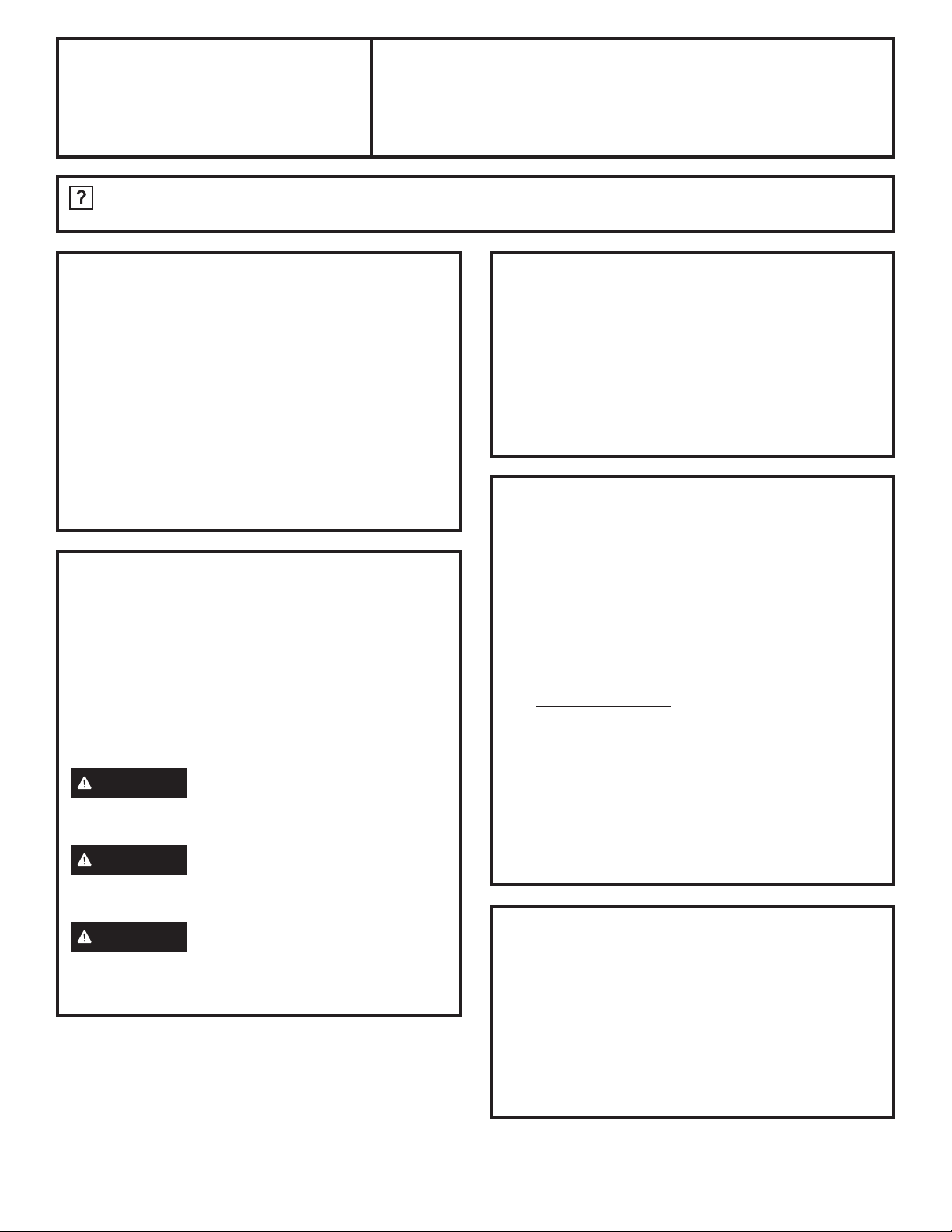
3. The cutout must be made to a maximum depth of
ó´DQGVKRXOGDOZD\VOHDYHDWOHDVWDǩ´JDSDOO
around the edge of the cooktop.
IMPORTANT: To ensure sufficient support for the
cooktop while cooking, reinforcing strips of wood
or solid surface material must be secured in place
below the edge of the cutout (see illustration).
Ensure sufficient support is provided in all
necessary locations on the countertop. Follow all
countertop manufacturer installation instructions.
Silicone Caulk
1/4”
Max.
1/8” Min.
Teflon tape
Glass
4. Vacuum dust and other particles from the cooktop
cutout.
5. Apply the black foam tape provided in the kit to
the top of the rabbeted edge of the countertop,
flush with the outer edge of the rabbet (see
picture in step 3.) The foam tape will keep the
silicone sealant from seeping between the
countertop and the underside of the cooktop.
Make sure the foam tape does not overlap - it
needs to be a single thickness for proper spacing.
6. Apply the Teflon tape to the underside of the
cooktop flush with the outside edge of the glass
and partially covering the metal flange (see picture
in step 3.) Trim the Teflon tape at the corners of
the cooktop to match the curve of the glass. The
Teflon tape will keep the silicone sealant from
seeping between the glass and the metal.
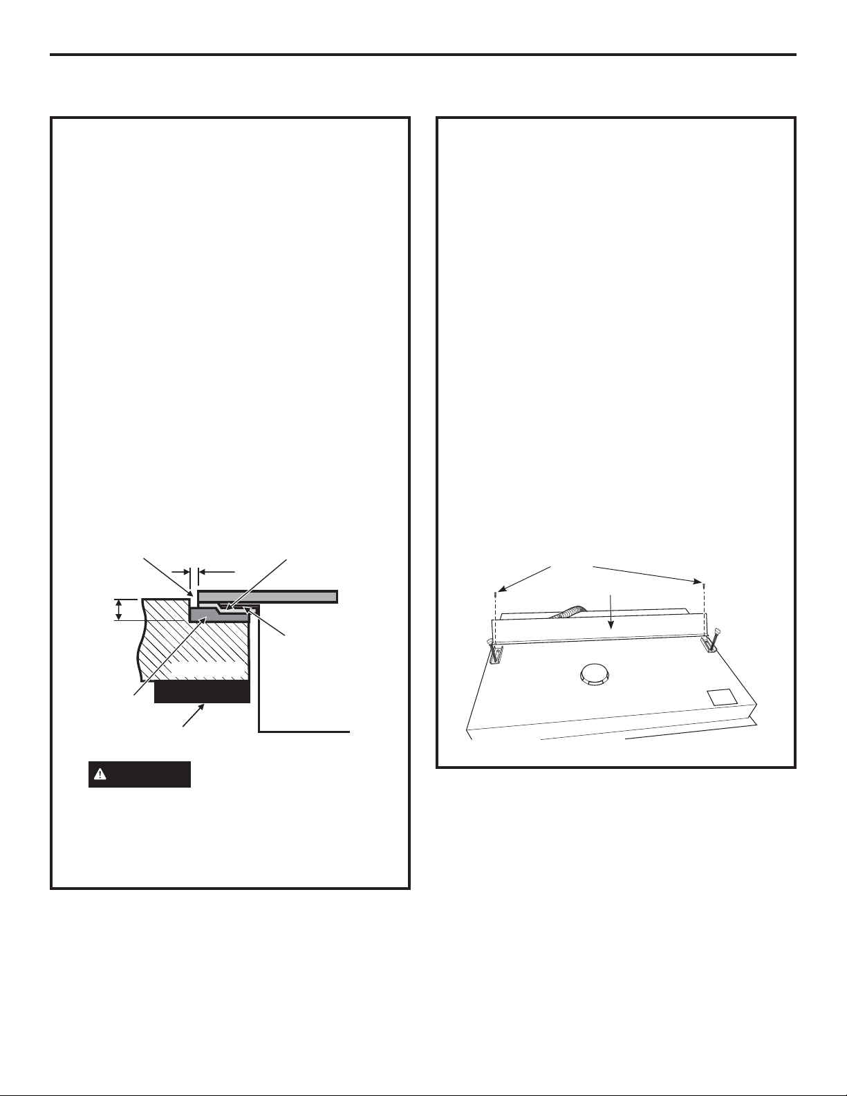
7. Install the hold-down brackets provided in the kit
onto the cooktop (both sides). DO NOT TIGHTEN
YET. Turn the brackets inwards to avoid
interference when dropping the cooktop into the
countertop. The baffle supplied with the cooktop
needs to be attached as well, unless the cooktop
is being installed over a single wall oven.
Screws
Baffle
Ensure cooktop sits
on the metal flange
on all four sides
Cooktop burner box
Foam tape
(Compressed)
Reinforcing strip
WARNING
Countertop
Failure to provide adequate
countertop reinforcement for cooktop may result
in damage to unit when weight is added to
cooktop during cooking.
Bottom of Cooktop
2
31-11024
Page 3

Installation Instructions
INSTALLING THE COOKTOP
8. Using the heavy duty suction cups (not provided)
lift and place the cooktop into the prepared
cutout.
CAUTION
surface is higher than the countertop surface
to prevent hot cookware from contacting the
countertop. If necessary, add wooden shims
under the foam tape where needed around the
perimeter of the cooktop to increase the height.
Make sure the foam and Teflon tapes contact
around the entire perimeter.
Hold Down
Bracket
Ensure that the cooktop
Cooktop
12. Using masking tape (not provided), place a border
around the edge of the cooktop cutout and the
edges of the glass. This will prevent the silicone
sealant from sticking to the top surface of the
countertop or to the glass surface of the cooktop.
WARNING
to come into contact with the top surface of the
glass cooktop.
Make sure tape does not cross
area to fill with silicone sealant
Do not allow silicone sealant
Glass
9. Make all wiring connections and check unit per
the installation instructions to ensure that it is
working correctly
10. Align the cooktop in the opening allowing for
equal clearance on all sides.
11. Access the bottom of the cooktop below the
countertop and tighten the screws on the
hold-down brackets. Turn the thumbscrew until it
touches the bottom of the countertop (see picture).
IMPORTANT: Turn the thumbscrew just until it
touches the bottom of the countertop. DO NOT
OVERTIGHTEN.
Countertop
Cooktop
Countertop
Masking tape
13. Ensure the area is well ventilated when applying
sealant. Apply high-temperature 100% silicone
sealant (not provided) into the opening between
the countertop edge and the edge of the glass
cooktop, one side at a time. It is important to wipe
away any sealant on the glass and countertop
immediately as the sealant can begin to form a
skin fairly quickly. Use only a high-temperature
100% silicone sealant that meets the listed
specifications. Use a caulking tool to finish the
surface of the bead to get a smooth look.
14. Do not touch the sealant, or move or use the
cooktop for the amount of time listed as the full
cure time for the sealant. Protect the area from
dust for at least 2 hours.
15. Allow the sealant to cure for the manufacturer’s
recommended time, then remove the masking
tape from the countertop and glass cooktop.
Clean any excess sealant on the cooktop and
countertop with the scraper.
31-11024
3
Page 4

Installation Instructions
INSTALLING THE COOKTOP
CUTOUT DIMENSIONS
These are the dimensions to which the countertop
should be cut for both the 30” and 36” wide cooktops.
Maximum depth of cut is 1/4“.
C
A
R 5/8”(1.6 cm)
All Four Corners
D
B
INSTALLING ABOVE A WALL OVEN
When installing the cooktop above a single wall oven,
do not install the baffle. The wall oven will need to
be removed during the cooktop installation and then
re-installed into its space.
IMPORTANT: Maintain a minimum distance of
31-1/4” from the top surface of the countertop to the
wall oven platform to ensure that the cooktop and wall
oven do not interfere with each other (see picture).
IMPORTANT: When the cooktop is installed above
a flush-mounted wall oven, the clearance from the
front edge of the countertop to the front edge of the
cooktop cutout is 2-1/2” minimum plus the wall oven
cleat setback (see picture).
(6.4 cm)
Cooktop
Wall Oven
31-1/4” min.
(79.4 cm)
From top surface of
countertop to top
surface of wall
oven platform
2-1/2” min.
+ wall oven cleat setback
4-3/4” min.
(12.1 cm)
SIDE VIEW
4
31-11024
 Loading...