

Page 1

Safety Information ..........2, 3
Warranty ........................ 4
Assistance / Accessories ......5
Using The Hood
Controls ...........................6
Fi lt ers .............................. 7
Care and Cleaning
Surfaces ...........................8
Lights ..............................8
Owner’s Manual and
Installation Instructions
JVC3300 Hood
Insert
Installation Instructions
Before You Begin ...................9
Installation Preparation ........10-13
Installing the Hood ............14, 15
Finalize Installation ................15
Troubleshooting Tips .........16
Custom Hood
For a Spanish version of this manual, visit
our Website at GEAppliances.com.
Para consultar una version en español
de este manual de instrucciones, visite
nuestro sitio de internet GEAppliances.com.
For a French version of this manual, visit
our Website at GEAppliances.com.
Pour obtenir une version française de
ce manuel, visitez notre site Web sur
GEAppliances.com.
Write the model and serial
numbers here:
Model # ______________________
Serial # _______________________
You can find them on a label on the
inside of the hood.
49-80778 10-15 GE
Page 2
IMPORTANT SAFETY INFORMATION.
READ ALL INSTRUCTIONS BEFORE USING.
This is the safety alert symbol. This symbol alerts you to potential hazards that can kill or hurt you and others.
All safety messages will follow the safety alert symbol and the word “DANGER”, “WARNING”, or “CAUTION”. These
words are defined as:
DANGER
WARNING
CAUTION
SAFETY PRECAUTIONS
SAFETY INFORMATION
WARNING
ELECTRIC SHOCK OR INJURY TO PERSONS,
OBSERVE THE FOLLOWING:
A. Use this unit only in the manner intended by the
manufacturer. If you have questions, contact the
manufacturer.
B. Before servicing or cleaning unit, switch power
off at service panel and lock the service
disconnecting means to prevent power from
being switched on accidentally. When the service
disconnecting means cannot be locked, securely
fasten a prominent warning device, such as a
tag, to the service panel.
C. Do not use this unit with any solid-state speed
control device.
D. This unit must be grounded.
CAUTION
ONLY. DO NOT USE TO EXHAUST HAZARDOUS
OR EXPLOSIVE MATERIALS AND VAPORS.
CAUTION
PROPERLY EXHAUST AIR, BE SURE TO DUCT
AIR OUTSIDE. DO NOT VENT EXHAUST AIR
INTO SPACES WITHIN WALLS OR CEILINGS OR
INTO ATTICS, CRAWL SPACES OR GARAGES.
Indicates a hazardous situation which, if not avoided, will result in death or serious injury.
Indicates a hazardous situation which, if not avoided, could result in death or serious injury.
Indicates a hazardous situation which, if not avoided, could result in minor or moderate injury.
TO REDUCE THE RISK OF FIRE,
FOR GENERAL VENTILATING USE
TO REDUCE RISK OF FIRE AND TO
WARNING
TO PERSONS IN THE EVENT OF A RANGE TOP
GREASE FIRE, OBSERVE THE FOLLOWING*:
A. SMOTHER FLAMES with a close-fitting lid,
cookie sheet or metal tray, then turn off the
burner. BE CAREFUL TO PREVENT BURNS.
If the flames do not go out immediately,
EVACUATE AND CALL THE FIRE
DEPARTMENT.
B. NEVER PICK UP A FLAMING PAN—You may
be burned.
C. DO NOT USE WATER, including wet dishcloths
or towels—a violent steam explosion will result.
D. Use an extinguisher ONLY if:
1. You know you have a Class ABC extinguisher,
and you already know how to operate it.
2. The fire is small and contained in the area
where it started.
3. The fire department is being called.
4. You can fight the fire with your back to an exit.
* Based on “Kitchen Fire Safety” published by NFPA.
TO REDUCE THE RISK OF INJURY
READ AND SAVE THESE INSTRUCTIONS
2
49-80778
Page 3

SAFETY PRECAUTIONS (Cont.)
SAFETY INFORMATION
WARNING
RANGE TOP GREASE FIRE:
A. Never leave surface units unattended at high
settings. Boilovers cause smoking and greasy
spillovers may ignite. Heat oils slowly on low or
medium settings.
B. Always turn hood ON when cooking on high heat
or when flambéing food (i.e. Crepes Suzette,
Cherries Jubilee, Peppercorn Beef Flambé).
C. Clean ventilating fans frequently. Grease should
not be allowed to accumulate on fan or filter.
D. Use proper pan size. Always use cookware
appropriate for the size of the surface element.
WARNING
ELECTRIC SHOCK OR INJURY TO PERSONS,
OBSERVE THE FOLLOWING:
A. Installation work and electrical wiring must be
done by qualified person(s) in accordance with
all applicable codes and standards, including
fire-rated construction.
B. Sufficient air is needed for proper combustion
and exhausting of gases through the flue
(chimney) of fuel burning equipment to prevent
back drafting. Follow the heating equipment
manufacturer’s guidelines and safety standards
such as those published by the National Fire
Protection Association (NFPA), the American
Society for Heating, Refrigeration and Air
Conditioning Engineers (ASHRAE) and the local
code authorities.
TO REDUCE THE RISK OF A
TO REDUCE THE RISK OF FIRE,
C. When cutting or drilling into wall or ceiling, do
not damage electrical wiring and other hidden
utilities.
D. Ducted fans must always be vented to the
outdoors.
E. When applicable, install any makeup
(replacement) air system in accordance
with local building code requirements. Visit
GEAppliances.com for available makeup air
solutions.
F. Turn off breaker to adjacent rooms while
working.
WARNING
USE ONLY METAL DUCTWORK.
Ŷ Do not attempt to repair or replace any part of
your hood unless it is specifically recommended
in this manual. All other servicing should be
referred to a qualified technician.
TO REDUCE THE RISK OF FIRE,
49-80778
READ AND SAVE THESE INSTRUCTIONS
3
Page 4

Thank You! ... for your purchase of a GE Brand appliance.
Register Y our Appliance: Register your new appliance on-line at your convenience!
www.geappliances.com/service_and_support/register/
Timely product registration will allow for enhanced communication and prompt service under the terms of your warranty,
should the need arise. You may also mail in the pre-printed registration card included in the packing material.
WARRANTY
GE Warranty
GEAppliances.com
All warranty service is provided by our Factory Service Centers, or an authorized Customer Care® technician.
To schedule service, on-line, visit us at www.geappliances.com/service_and_support/, or call 800.GE.CARES
(800.432.2737). Please have serial number and model number available when calling for service.
Servicing your appliance may require the use of the onboard data port for diagnostics. This gives a GE factory
service technician the ability to quickly diagnose any issues with your appliance and helps GE improve its products
by providing GE with information on your appliance. If you do not want your appliance data to be sent to GE, please
advise your technician not to submit the data to GE at the time of service.
For the period of one year from the date of the original purchase, GE will provide any part of the hood insert which
fails due to a defect in materials or workmanship. During this limited one-year warranty, GE will also provide, free of
charge, all labor and in-home service to replace the defective part.
What GE will not cover:
Ŷ Service trips to your home to teach you how to use
the product.
Ŷ Improper installation, delivery or maintenance.
Ŷ Failure of the product if it is abused, misused,
modified or used for other than the intended purpose
or used commercially.
Ŷ Replacement of house fuses or resetting of circuit
breakers.
Ŷ Damage to the product caused by accident, fire,
floods or acts of God.
Ŷ Damage to finish, such as surface rust, tarnish, or
small blemishes not reported within 48 hours of
delivery.
Ŷ Incidental or consequential damage caused by
possible defects with this appliance.
Ŷ Damage caused after delivery.
Ŷ Product not accessible to provide required service.
Ŷ Service to repair or replace light bulbs, except for
LED lamps.
EXCLUSION OF IMPLIED WARRANTIES
Your sole and exclusive remedy is product repair as provided in this Limited Warranty. Any implied warranties,
including the implied warranties of merchantability or fitness for a particular purpose, are limited to one year or the
shortest period allowed by law.
This warranty is extended to the original purchaser and any succeeding owner for products purchased for home use
within the USA. If the product is located in an area where service by a GE Authorized Servicer is not available, you
may be responsible for a trip charge or you may be required to bring the product to an Authorized GE Service location
for service. In Alaska, the warranty excludes the cost of shipping or service calls to your home.
Some states do not allow the exclusion or limitation of incidental or consequential damages. This warranty gives you
specific legal rights, and you may also have other rights which vary from state to state. To know what your legal rights
are, consult your local or state consumer affairs office or your state’s Attorney General.
Warrantor: General Electric Company. Louisville, KY 40225
Staple your receipt here. Proof of the original purchase
date is needed to obtain service under the warranty.
Extended Warranties: Purchase a GE extended warranty and learn about special discounts that are available while
your warranty is still in effect. You can purchase it on-line anytime
www.geappliances.com/service_and_support/shop-for-extended-service-plans.htm
or call 800.626.2224 during normal business hours. GE Consumer Home Services will still be there after your
warranty expires.
4
49-80778
Page 5

Have a question or need assistance with your appliance?
Try the GE Appliances Website (www.geappliances.com/service_and_support/) 24 hours a day, any day of the
year! For greater convenience and faster service, you can now download Owner’s Manuals, order parts or even
schedule service on-line.
Schedule Service: Expert GE repair service is only one
step away from your door. Get on-line and schedule your
service at www.geappliances.com/service_and_support/
Or call 800.GE.CARES (800.432.2737) during normal
business hours.
Parts and Accessories: Individuals qualified to service
their own appliances can have parts or accessories sent
directly to their homes (VISA, MasterCard and Discover
cards are accepted).Order on-line today, 24 hours
every day or by phone at 800.626.2002 during normal
business hours.
Instructions contained in this manual cover procedures
to be performed by any user. Other servicing generally
should be referred to qualified service personnel. Caution
must be exercised, since improper servicing may cause
unsafe operation.
Real Life Design Studio: GE supports the Universal
Design concept of products, services and environments
that can be used by people of all ages, sizes and
capabilities. We recognize the need to design for a wide
range of physical and mental abilities and impairments.
For details of GE’s Universal Design applications,
including kitchen design ideas for people with disabilities,
check out our Website today. For the hearing impaired,
please call 800.TDD.GEAC (800.833.4322).
Contact Us: If you are not satisfied with the service you
receive from GE, contact us on our Website with all the
details including your phone number, or write to:
General Manager, Customer Relations
GE Appliances, Appliance Park Louisville, KY 40225
Accessories
Looking For Something More?
GE offers a variety of accessories to improve your cooking and maintenance experiences!
To place an order visit us online at:
www.GEApplianceParts.com or call 800.626.2002
The following products and more are available:
ASSISTANCE / ACCESSORIES
Parts
Liners 30":JXL30 36":JXL36
Recirculation Kit JXN30
Grease Filter WB02X26416
How to Remove Protective Shipping Film and Packaging Tape
Carefully grasp a corner of the protective shipping film
with your fingers and slowly peel it from the appliance
surface. Do not use any sharp items to remove the film.
Remove all of the film before using the appliance for the
first time.
To assure no damage is done to the finish of the
product, the safest way to remove the adhesive from
packaging tape on new appliances is an application of
a household liquid dishwashing detergent. Apply with a
soft cloth and allow to soak.
NOTE: The adhesive must be removed from all parts.
49-80778
5
Page 6
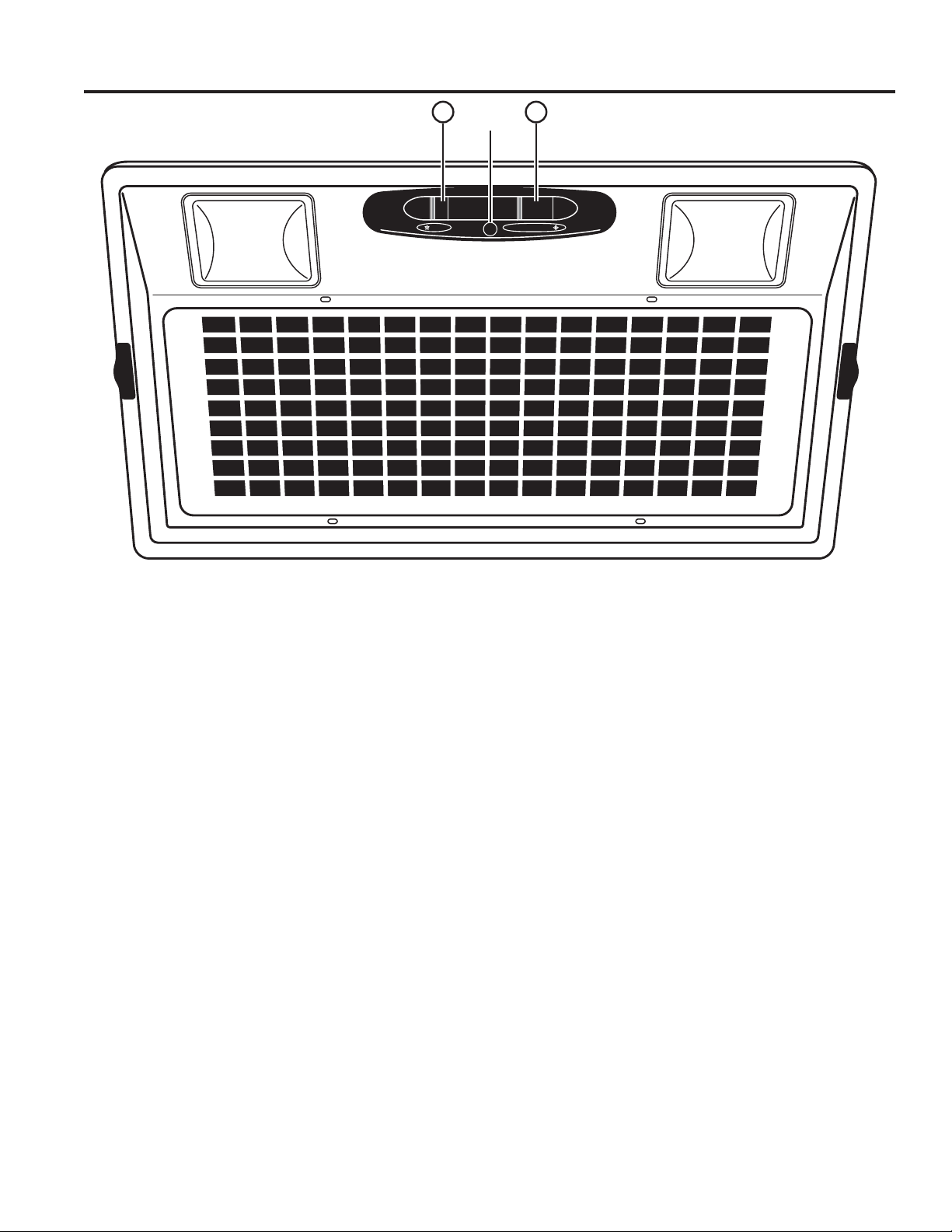
Controls
USING THE HOOD: Controls
Pilot
1
Lamp
0 1 0 1 2 3
2
1. Light Switch: 0 is OFF. Move switch to 1
for ON.
2. Blower Switch: 0 is OFF. Move switch to 1 for
LOW speed, 2 for MEDIUM speed, and 3 for HIGH
speed. The pilot lamp illuminates when the blower
switch is set to 1, 2, or 3.
Heat Sensor
Your hood is equipped with a HEAT SENSOR
thermostat. This thermostat is a device that will turn on
or speed up the blower if it senses excessive heat above
the cooking surface.
1. If blower is OFF - it turns blower ON to HIGH speed.
2. If blower is ON at a lower speed setting - it turns
blower up to HIGH speed.
When the temperature level drops to normal, the blower
will return to its original setting.
6
49-80778
Page 7
Filters
Be sure the circuit breaker is off and all surfaces are cool before cleaning or servicing any part of the vent hood.
Metal Grease Filter
The metal filters trap grease during cooking.
The filter must ALWAYS be in place when the hood is in
use. The grease filter is dishwasher-safe and should be
cleaned every 6 months, or as needed.
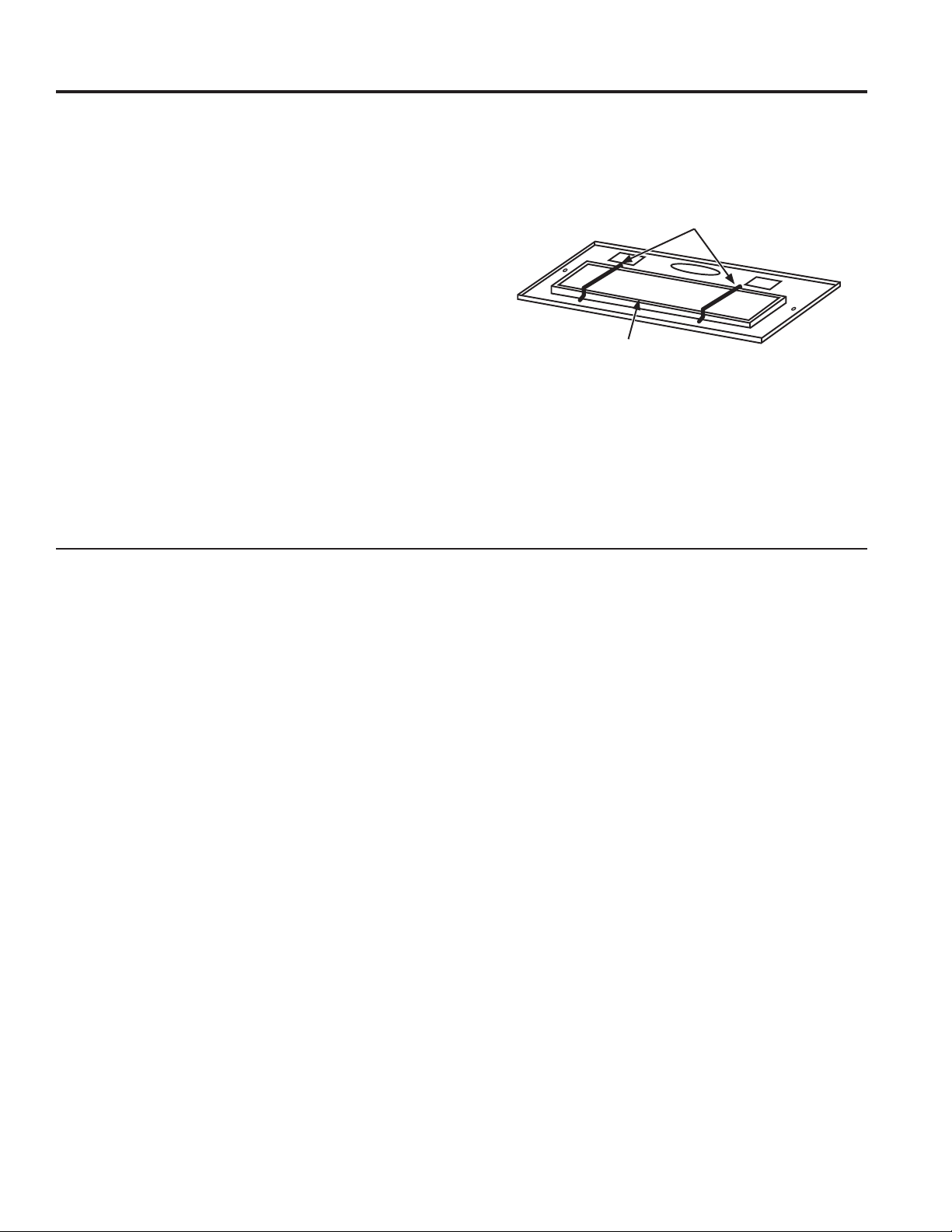
To remove:
Remove the access panel by sliding the two side
latches. Remove the wire retainers and then remove the
grease filter.
Wire Retainers
USING THE HOOD: Filters
To replace:
Align the grease filter and install the wire retainers.
Replace the access panel.
To clean, swish the filter in hot soapy water and rinse
in clean water or wash it in the dishwasher. Do not use
abrasive cleansers.
NOTE: Some discoloration may occur in the dishwasher.
For Recirculation Installation Only
Charcoal Filter (Not Included)
When the hood is installed with the recirculation kit
JXN30, there is a charcoal filter on top of the grease
filter. To remove and reinstall the charcoal filter, follow
the steps for the grease filter.
NOTE: DO NOT rinse, or put charcoal filter in an
automatic dishwasher.
The charcoal filter cannot be cleaned. It must be
replaced. It is recommended that the charcoal filter
be replaced every 6 months or if it is noticeably dirty
or discolored.
Order Charcoal Filter WB28X10120
Grease Filter
To inquire about purchasing replacement charcoal filters
or to find the location of a dealer nearest you, please call
our toll-free number:
National Parts Center 800.626.2002
49-80778
7
Page 8
Surfaces
Painted Surfaces
Do not use a steel wool pads or other abrasive
cleaners; they will scratch the surface.
Clean grease-laden surfaces of the hood frequently. To
clean the hood surface, use a hot, damp cloth with a
mild detergent suitable for painted surfaces. About one
tablespoon of ammonia may be added to the water. Use
a clean, hot, damp cloth to remove soap. Dry with a dry,
clean cloth.
NOTE: When cleaning, take care not to come in contact
with filters and other non-enameled surfaces.
Light Bulbs
CAUTION
be certain that you do not touch the light with
moist hands or cloth. A warm or hot light may
break if touched with a moist surface. Always
let the light cool completely before cleaning
around it.
When cleaning the hood surfaces,
CAUTION
touching.
To change the light bulbs:
1. Before attempting to replace the lights, make sure that
CARE AND CLEANING: Surfaces/Lights
the light switch is turned off.
2. Remove the access panel (slide the two side latches).
3. Replace with candelabra base light bulbs (MAX 40W,
120V, E12, Type B or Type T8 Bulb).
CAUTION
4. Reinstall the access panel.
Allow lights to cool before
BULB MAY BE HOT!
8
49-80778
Page 9
Installation
Custom Hood Insert
JVC3300 Hood
Instructions
“If you have questions, call 800.GE.CARES (800.432.2737) or visit our website at:
GEAppliances.com”
BEFORE YOU BEGIN
Read these instructions completely and
carefully.
•
IMPORTANT — Save these
instructions for local inspector’s use.
•
IMPORTANT — Observe all governing
codes and ordinances.
•
Note to Installer – Be sure to leave these
instructions with the Consumer.
• Note to Consumer – Keep these
instructions for future reference.
• Skill level – Installation of this vent hood
requires basic mechanical and electrical
skills.
• Proper installation is the responsibility of the
installer.
• Product failure due to improper installation is
not covered under the Warranty.
CAUTION
RECOMMENDED FOR PROPER
INSTALLATION.
TWO PEOPLE ARE
WARNING
FIRE, ELECTRIC SHOCK OR INJURY TO
PERSONS, OBSERVE THE FOLLOWING:
A. Installation work and electrical wiring
must be done by qualified person(s) in
accordance with all applicable codes and
standards, including fire-rated construction.
B. Sufficient air is needed for proper
combustion and exhausting of gases
through the flue (chimney) of fuel burning
equipment to prevent back drafting. Follow
the heating equipment manufacturer’s
guidelines and safety standards such
as those published by the National Fire
Protection Association (NFPA), the
American Society for Heating, Refrigeration
and Air Conditioning Engineers (ASHRAE)
and the local code authorities.
C. When cutting or drilling into wall or ceiling,
do not damage electrical wiring and other
hidden utilities.
D. Ducted fans must always be vented to the
outdoors.
E. Turn off breaker to adjacent rooms while
working.
TO REDUCE THE RISK OF
FOR YOUR SAFETY:
WARNING
switch power off at service panel and lock the
service disconnecting means to prevent power
from being switched on accidentally. When the
service disconnecting means cannot be locked,
securely fasten a prominent warning device,
such as a tag, to the service panel.
49-80778
Before beginning the installation,
WARNING
FIRE, USE ONLY METAL DUCT WORK.
TO REDUCE THE RISK OF
9
Page 10
Installation Preparation
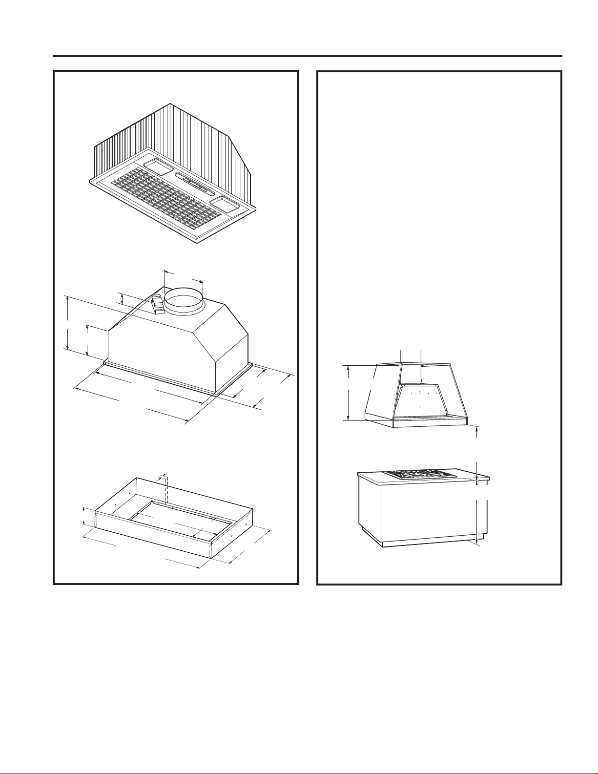
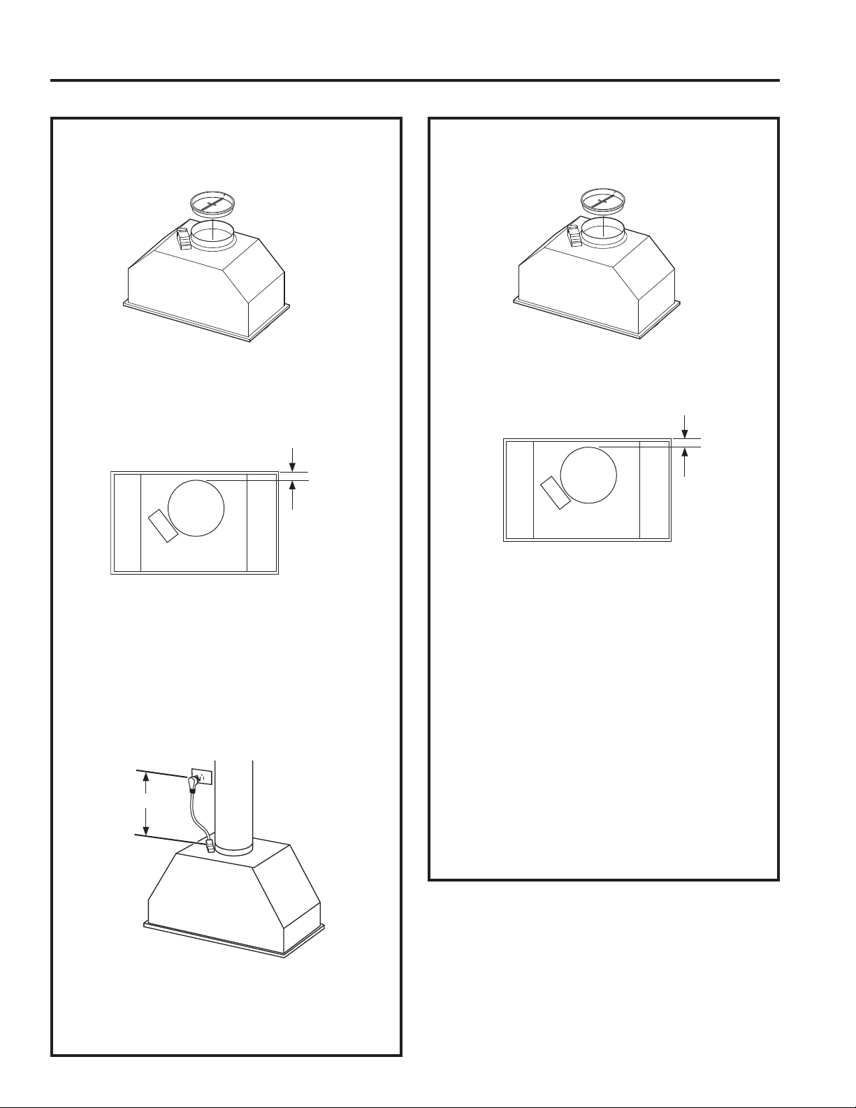
PRODUCT DIMENSIONS
INSTALLATION PREPARATION
2"
9-5/8"
3-1/4"
5-7/8"
INSTALLATION CLEARANCES
This vent hood and liner assembly must be installed
24" required minimum and 36" recommended
maximum above the cooking surface.
• Always refer to the cooktop or range installation
instructions for product-specific clearances.
NOTE: Installation height should be measured from
the cooking surface to the bottom edge of the metal
hood liner or cabinet surface.
NOTE: UL requires any combustible surface to be a
minimum of 30" above the cooking surface.
• The custom cabinet internal height must be 16"
minimum.
• This hood can be vented to the outdoors, or it
can be installed for recirculating operation. For
recirculating operation, refer to Recirculating
Installation Planning.
• This hood may be mounted onto a cabinet or
installed over an island.
19-7/16"
20-1/2"
Liners (Optional)
4"
28-7/16" (JXL30)
34-7/16" (JXL36)
19-9/16"
10-3/16"
11-1/4"
16" min.
*24" Minimum required
*36" Maximum recommended
1"
36" min.
10-1/4"
17-1/4"
10
49-80778
Page 11
Installation Preparation
INSTALLATION PREPARATION
ADVANCE PLANNING
Duct Install Planning
• This hood is designed to be vented vertically
through the ceiling. Use a 6" round duct. Use
locally supplied elbows to vent horizontally
through the rear wall.
• Use metal ductwork only.
• Determine the exact location of the vent hood.
• Plan the route for venting exhaust to the outdoors.
To maximize the ventilation performance of the
vent system:
1. Minimize the duct run length and number of
transitions and elbows.
2. Maintain a constant duct size.
3. Seal all joints with duct tape to prevent any
leaks.
4. Do not use any type of flexible ducting.
• Install a wall cap or roof cap with damper at the
exterior opening. Purchase the wall or roof cap
and any transition and length of duct needed in
advance.
• When applicable, install any makeup
(replacement) air system in accordance with local
building code requirements. Visit GEAppliances.
com for available makeup air solutions.
Wall and Ceiling Framing for Adequate
Support
This vent hood is heavy and the cabinet structure
needs to support the weight of the loaded insert
sleeve. Adequate structural support must be
provided in all types of installations.
• Installation will be easier if the vent hood is
installed before the cooktop is installed.
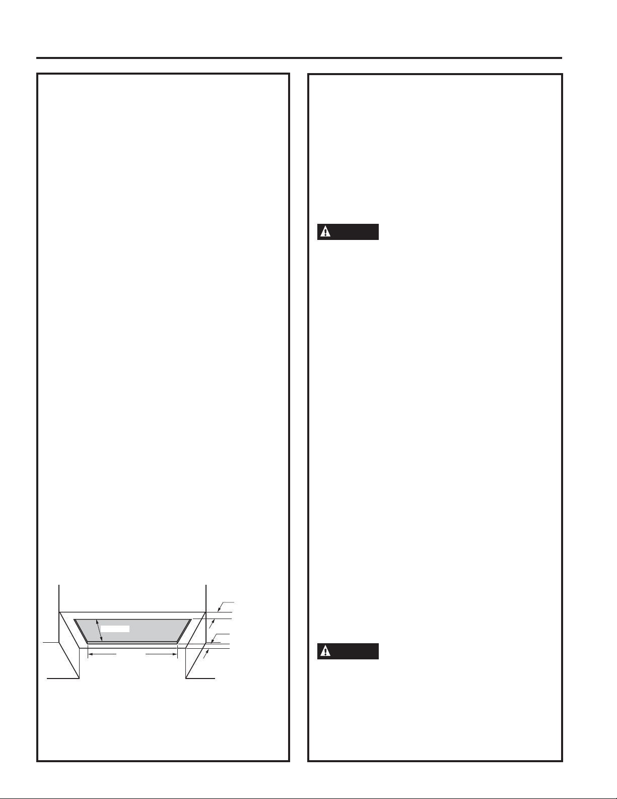
Custom Cabinet Frame Planning
• The custom canopy or cabinet should have a
rectangular hole to accommodate the custom hood
insert by itself, or with the liner. This hole is the
same size for both a wall installation and an island
installation.
10-1/4"
19-1/2"
Metal Liners
• Metal liners (30" width JXL30 and 36" width JXL36)
are optional but are recommended for installation
heights below 30" for cabinetry protection. You can
construct a custom metal (or non-combustible) liner
when a larger liner is needed.
Front of hole
must be 3"
minimum from
cabinet front
Back of hole
must be 1"
minimum from
back wall
Recirculation Install Planning
A recirculation duct kit JXN30 is available for
recirculation installation.
Power Supply Planning
The location of the power supply connection
is called out in the Wall Installation and Island
Installation sections on page 13.
POWER SUPPLY
IMPORTANT – (Please read carefully)
WARNING
FOR PERSONAL SAFETY, THIS APPLIANCE
MUST BE PROPERLY GROUNDED.
In the event of an electrical short circuit, grounding
reduces the risk of electric shock by providing an
escape wire for the electric current. This appliance
is equipped with a cord having a grounding wire with
a grounding plug. The plug must be plugged into an
outlet that is properly installed and grounded.
Remove house fuse or open circuit breaker before
beginning installation.
Do not use an extension cord or adapter plug with
this appliance. If the power supply cord is too short,
have a qualified electrician install an outlet near the
appliance. Do not operate any fan with a damaged
cord or plug. Discard fan or return to an authorized
service facility for examination and/or repair. Follow
National Electrical Codes or prevailing local codes
and ordinances.
Electrical supply
These vent hoods must be supplied with 120V,
60Hz, and connected to an individual, properly
grounded branch circuit, and protected by a 15 or
20 amp circuit breaker or time delay fuse.
• Wiring must be 2 wire with ground.
• If the electrical supply does not meet the above
requirements, call a licensed electrician before
proceeding.
• Route house wiring as close to the installation
location as possible in the ceiling or wall.
• Connect the wiring to the house wiring in
accordance with local codes.
WARNING
equipment-grounding conductor can result
in a risk of electric shock. Consult a qualified
electrician if the grounding instructions are
not completely understood, or if doubt exists
as to whether the appliance is properly
grounded.
The improper connection of the
49-80778
11
Page 12
Installation Preparation
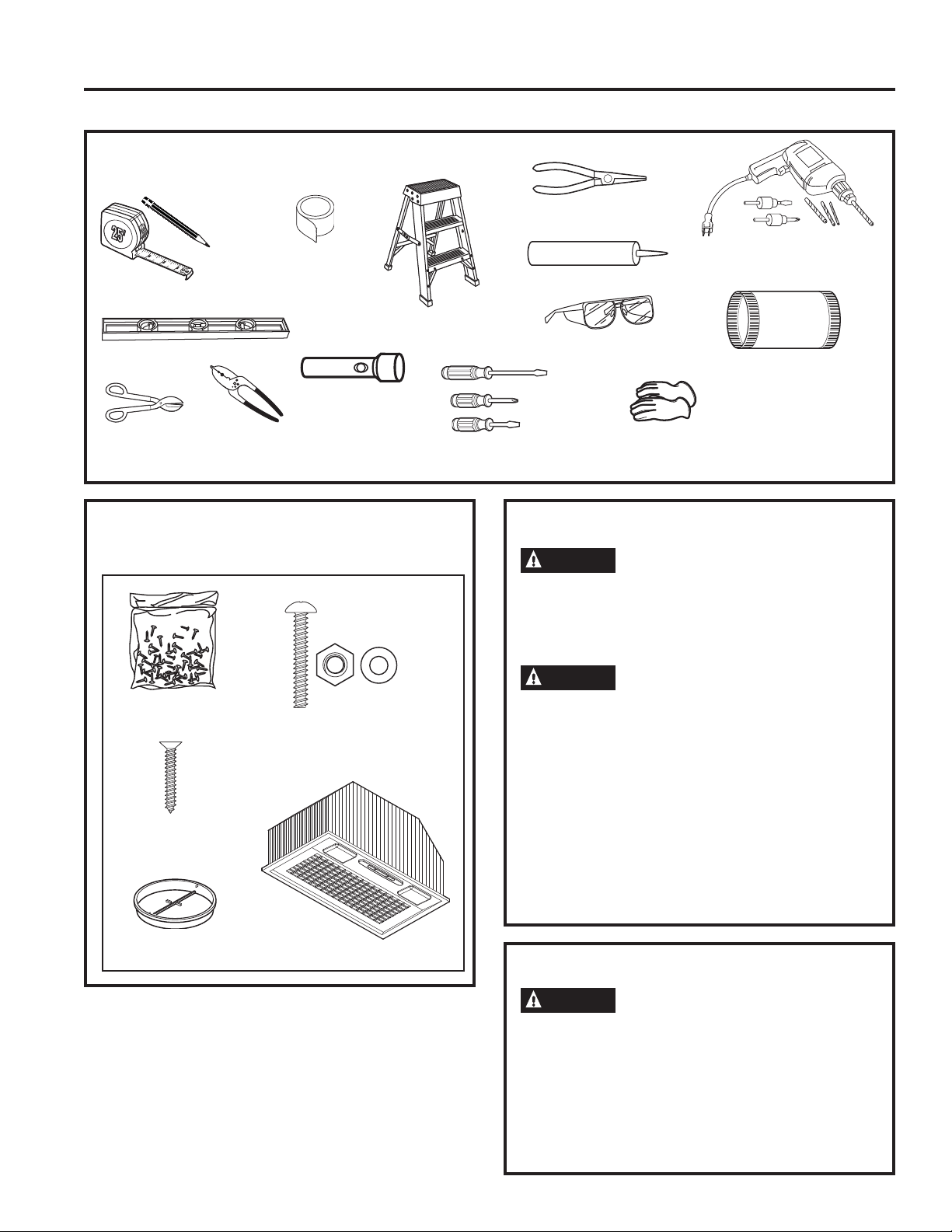
TOOLS AND MATERIALS REQUIRED
(NOT SUPPLIED)
Aluminized
duct tape
Pencil and tape measure
Step ladder
Spirit level
Flashlight
Needle-nose pliers
Electric drill and
appropriate bits
Silicone
Safety glasses
6" ducting and
caps as needed
INSTALLATION PREPARATION
Tin snips
Wire cutter/
stripper
PARTS PROVIDED
Locate the parts packed with the hood.
Hardware
bag
Phillips head
wood screws
Phillips head machine
screws, nuts and washers
Hood
Phillips and flatblade screwdrivers
PLAN THE INSTALLATION
properly exhaust air, be sure to duct the
air outside – Do not vent exhaust air into
spaces within walls or ceilings or into attics,
crawl spaces, or garages.
PERSONAL INJURY HAZARD
It is recommended that 2 people are used to
install the range hood. Failure to properly
lift rangehood could result in damage to the
product or personal injury.
NOTE: This rangehood can be installed as
either ducted or recirculation. In a ducted
application, this rangehood can be vented
through the wall or ceiling. When installed for
recirculation, the rangehood vents back into the
room.
CAUTION
WARNING
Gloves
To reduce risk of fire and to
12
Damper
assembly
REMOVE THE PACKAGING
CAUTION
sharp edges.
• Remove the duct covers.
• Remove the hardware bag, literature package
and other boxed parts.
• Remove and properly discard the protective
plastic wrapping and other packaging
materials.
Wear gloves to protect against
49-80778
Page 13
Installation Preparation
INSTALLATION PREPARATION
PREPARE FOR CABINET INSTALLATION
1. Insert the damper assembly into the hood
exhaust duct.
2. The hood should be centered left to right over the
cooktop.
NOTE: The exhaust duct on the hood is closer to
the rear of the hood. It is important to plan for the
alignment to the connection point of the hood.
9/16"
PREPARE FOR ISLAND INSTALLATION
1. Insert the damper assembly into the hood
exhaust duct.
2. The hood should be centered left to right over the
cooktop.
NOTE: The exhaust duct on the hood is closer to
the rear of the hood.
9/16"
3. The back surface of the hood must be 1"
minimum from the back wall. The front surface
of the hood must be 3" minimum from the front
custom cabinet panel.
4. The metal liner should be used when the
hood installation height is less than 30". The
liner dimensions are provided in the Product
Dimensions section.
5. The electrical receptacle location maximum
dimension is shown here.
33-7/16"
The front to back location of the hood over
the cooktop can be chosen by the installer
or homeowner.The island duct run is usually
centered over the cooktop and it is important to
plan for the alignment to the connection point of
the hood.
4. The metal liner should be used when the
hood installation height is less than 30". The
liner dimensions are provided in the Product
Dimensions section.
5. Locate the electrical receptacle in the cabinetry
or area above the hood so that it complies with
local and electrical codes.
6. The custom cabinet should provide for removal
of panels to provide access to the electrical cord
plug and to the ducting and its connection to the
hood in case of any need for servicing or other
reasons.
6. The custom cabinet should provide for removal
of panels to provide access to the electrical cord
plug and to the ducting and its connection to the
hood in case of any need for servicing or other
reasons.
49-80778
13
Page 14
Installation
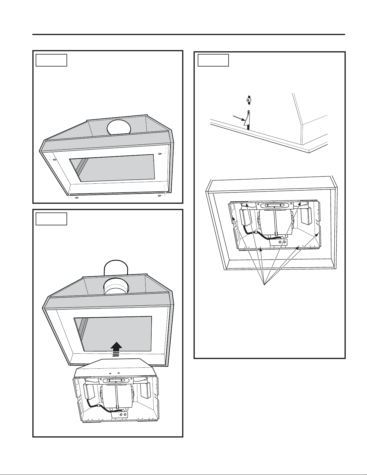
STEP 1 INSTALL HOOD LINER (If Used)
1. The rectangular opening in framing or custom
cabinet must be sized for the liner outside and
inside dimensions. Refer to Product Dimensions
INSTALLATION
section.
2. Secure the liner with the 4 screws that are
provided with the liner.
STEP 2 INSTALL THE HOOD
1. Confirm the damper is in place in the hood
exhaust opening.
2. Insert the hood and power cord into the cabinet
opening or into the liner opening.
STEP 2 INSTALL THE HOOD (Cont)
3. Fasten with 4 screws. There is a spring locking
clip on one side of the hood to assist with holding
one side up while installing the screws.
Spring
Locking
Clip
NOTE: 4 screws can be installed into the sides or
into the front and back holes in the hood.
14
Possible screw
locations
4. If the liner is used, an alternate mounting method
is to assemble the hood to the liner using the 4
machine screws, washers, and nuts provided.
Then assemble the liner to the framing or custom
cabinet using the 4 screws provided with the liner.
5. Once the hood is in place, seal the duct to the
hood with duct tape.
49-80778
Page 15
Installation
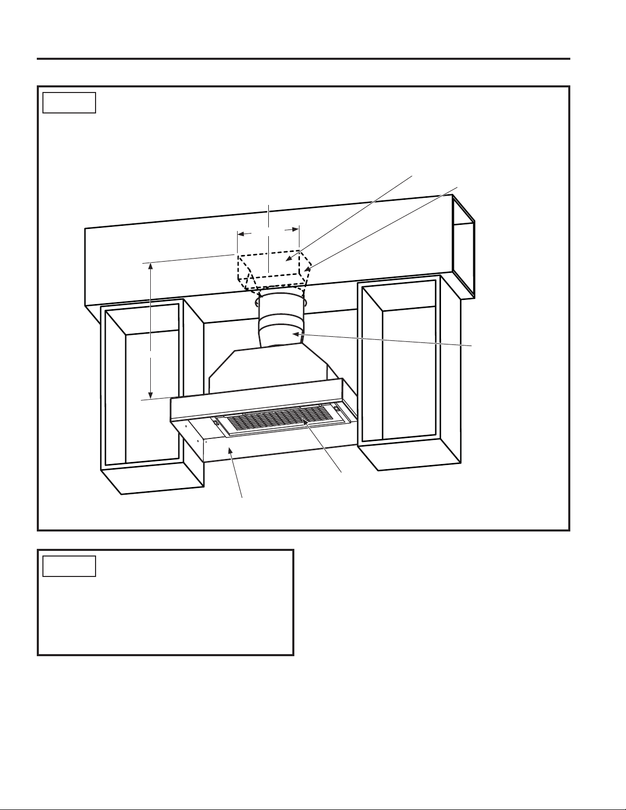
STEP 3 RECIRCULATION KIT (If Used)
1. Cut a hole into the soffit for the exhaust duct.
2. Install the vent grill over the exhaust duct.
3. Seal the duct joints with duct tape.
Hood Center Line
C
L
10-1/4"
INSTALLATION
Soffit Cutout
90° Angle Boot
25"
Liner
STEP 4 FINALIZE INSTALLATION
1. Plug in the hood.
2. Install the access panel.
3. Check operation of the lights and blower.
4. Finish the custom cabinetry.
6" Round to
7" Round
Transition
Combination Filter
49-80778
15
Page 16

Troubleshooting tips ... Before you call for service
Save time and money! Review the charts on the following pages first and you may not need to call for service.
Problem Possible Cause What To Do
Fan/Light does not operate
when slide switch is turned
ON
Loud or abnormal airflow
noise
Fan fails to circulate
air or moves air slower
than normal and/or fan is
making loud or abnormal
airflow noise
TROUBLESHOOTING TIPS
Early light failure Light wattage is too high. Replace with correct wattage.
Fan automatically turns on
and can not be turned off.
Fan keeps going off and on The motor is probably
A house fuse may be blown or
a circuit breaker tripped.
Wrong duct size used in
installation.
Obstructions in duct work. Make sure nothing is blocking the vent. Make sure your
Damper blade on wall or roof
cap may not be open.
Metal grease filter and charcoal
filter (if present) may be dirty.
Insufficient makeup
(replacement) air
This is normal. The sensor feature will automatically turn the fan on if
overheating and turning itself
off. This can be harmful to the
motor.
Replace fuse or reset circuit breaker.
This hood requires 6” ducting to perform optimally. Using
smaller duct pipe will cause reduced venting. Minimize
the duct run length and number of transitions and elbows.
GE service technicians cannot correct this issue if
installed improperly.
wall or roof cap has a blade or door.
Make sure damper swings freely. Damper blades may flip
over and will not fully open when this happens. Adjust to
original position.
Clean the metal grease filter and replace charcoal filter (if
present). See Care and Cleaning of the Vent Hood.
Sufficient makeup (replacement) air is required for
exhausting appliances to operate to rating. Check with
local building codes, which may require or strongly
advise the use of makeup air. Visit GEAppliances.com for
available makeup air solutions.
cooking temperature becomes too hot. The fan will then
turn off when temperatures cool to an appropriate level.
Check to be sure the filters are clean. If off and on
cycling continues, call for service.
16
49-80778
Page 17

Renseignements
de sécurité .............. 2, 3
Garantie .....................4
Assistance / Accessoires ..... 5
Utilisation de la hotte
Commandes ..................6
Filtres. .......................7
Entretien et nettoyage
Des surfaces. .................8
Lampes ......................8
Instructions d’installation
Avant de commencer. ...........9
Préparation de l’installation . . .10-13
Installation de la hotte .......14, 15
Finaliser l’installation ...........15
Conseils de dépannage .....16
Manuel du propriétaire et
instructions d’installation
Hotte JVC3300
Hotte Encastrable
Et Adaptable
Inscrivez les numéros de modèle et
de série ici :
No modèle # __________________
No de série # __________________
Vous pouvez les trouver sur une
étiquette sur l’intérieur de la hotte.
49-80778 10-15 GE
Page 18

RENSEIGNEMENTS DE SÉCURITÉ IMPORTANTS.
LISEZ TOUTES LES INSTRUCTIONS AVANT L’UTILISATION.
Ce symbole représente une alerte de sécurité. Ce symbole vous avise de dangers possibles pouvant causer la mort,
des blessures ou autres. Tous les messages de sécurité seront précédés du symbole d’alerte de sécurité ainsi que des mots
« DANGER », « AVERTISSEMENT » ou « MISE EN GARDE ». Ces messages sont les suivants :
DANGER
AVERTISSEMENT
ATTENTION
CONSIGNES DE SÉCURITÉ
Signale une situation qui présente un danger imminent et qui, si elle n’est pas évitée, entraînera des blessures
graves, voire la mort.
Signale une situation qui présente un danger imminent et qui, si elle n’est pas évitée, peut entraîner des
blessures graves, voire la mort.
Signale une situation qui présente un danger imminent et qui, si elle n’est pas évitée, peut entraîner
des blessures mineures ou graves.
.
AVERTISSEMENT
D’INCENDIE, DE SECOUSSE ÉLECTRIQUE OU
DE BLESSURE CORPORELLE, OBSERVEZ LES
RENSEIGNEMENTS DE SÉCURITÉ
PRÉCAUTIONS SUIVANTES :
A. N’utilisez cet appareil que de la manière prévue par
le fabricant. Si vous avez des questions, appelez le
fabricant.
B. Avant de réparer ou de nettoyer votre appareil,
débranchez le courant au niveau du panneau
de service et verrouillez les mécanismes de
débranchement de service pour éviter tout
branchement accidentel au courant. Si vous
ne pouvez pas verrouiller les mécanismes de
débranchement de service, attachez soigneusement
un avertissement bien visible, comme une étiquette,
au panneau de service.
C N’utilisez jamais cet appareil avec un mécanisme de
réglage de la vitesse à semi-conducteurs.
D. Cet appareil doit être bien mis à la terre.
ATTENTION
VENTILATION GÉNÉRALE. N’UTILISEZ JAMAIS
POUR L’ÉCHAPPEMENT DE MATIÈRES ET DE
VAPEURS EXPLOSIVES.
ATTENTION
D’INCENDIE ET ÉVACUER L’AIR VICIÉ
CORRECTEMENT, ASSUREZ-VOUS DE DIRIGER
L’AIR DES CONDUITS À L’EXTÉRIEUR. NE VENTILEZ
PAS L’AIR D’ÉVACUATION DANS DES ESPACES
SITUÉS ENTRE DES MURS, DES PLAFONDS,
DES COMBLES, DES VIDES SANITAIRES OU DES
GARAGES.
POUR RÉDUIRE LE RISQUE
UNIQUEMENT À USAGE DE
POUR RÉDUIRE LE RISQUE
AVERTISSEMENT
BLESSURE CORPORELLE SI DE LA GRAISSE
PREND FEU SUR LA SURFACE DE CUISSON DU
FOUR, SUIVEZ LES INSTRUCTIONS SUIVANTES* :
A. ÉTOUFFEZ LES FLAMMES avec un couvercle qui
convient, une tôle à biscuits ou un plateau en métal,
puis éteignez le brûleur. FAITES BIEN ATTENTION
DE NE PAS VOUS BRÛLER. Si les flammes ne
s’éteignent pas immédiatement, SORTEZ ET
APPELEZ LES POMPIERS.
B. NE DÉPLACEZ JAMAIS UNE CASSEROLLE QUI
FLAMBE-Vous pouvez vous brûler.
C. N’UTILISEZ JAMAIS D’EAU, en particulier de
serviette ou de chiffon mouillé – il se produira une
explosion violente de vapeur brûlante.
D. N’UTILISEZ UN EXTINCTEUR que si :
1. Vous avez un extincteur de classe ABC et vous
savez comment l’utiliser;
2. Le feu est réduit et confiné à l’endroit où il a
commencé;
3. Vous avez déjà appelé les pompiers;
4. Vous combattez les flammes en tournant le dos à
une sortie.
* Basé sur l’ouvrage intitulé «Kitchen Fire Safety Tips»
publié par la NFPA.
POUR RÉDUIRE LE RISQUE DE
LISEZ ET CONSERVEZ CES INSTRUCTIONS
2
49-80778
Page 19

CONSIGNES DE SÉCURITÉ (Suite)
RENSEIGNEMENTS DE SÉCURITÉ
AVERTISSEMENT
GRAISSE SUR LA SURFACE DE CUISSON DU FOUR :
A. Ne laissez jamais sans surveillance les unités de
cuisson de surface à une température élevée. Le
bouillonnement occasionne des débordements
fumants et graisseux qui peuvent prendre feu.
Chauffez à feu doux les substances huileuses, avec
un réglage bas ou moyen.
B. Mettez toujours la hotte en marche si vous cuisez à
température élevée ou préparez des mets flambés
(p.ex. crêpes suzettes, cerises jubilé, flambé de bœuf
au poivre).
C. Nettoyez les mécanismes de ventilation fréquemment.
Il ne faut pas permettre une accumulation de graisse
sur le ventilateur ou sur le filtre.
D. Utilisez une casserole de bonne taille. Utilisez
toujours un ustensile de cuisine qui convienne au
diamètre de l’élément de cuisson.
AVERTISSEMENT
D’INCENDIE, DE SECOUSSE ÉLECTRIQUE OU
DE BLESSURE CORPORELLE, OBSERVEZ LES
PRÉCAUTIONS SUIVANTES :
A. Vous devez faire exécuter tous les travaux
d’installation et de câblage électrique par une
personne qualifiée, conformément à tous les codes
et les normes en vigueur, en particulier ceux de
construction relatifs aux incendies.
B. Vous devez assez d’air pour avoir une bonne
combustion et permettre l’évacuation des gaz par le
conduit de cheminée du matériel de combustion du
carburant, afin d’éviter tout retour d’air. Suivez les
directives du fabricant de matériel de combustion
et les normes de sécurité comme celles publiées
par la National Fire Protection Association (NFPA)
et l’American Society for Heating, Refrigeration and
Air Conditioning Engineers (ASHRAE), ainsi que les
modalités des codes locaux. Le cas échéant, installez
un système de ventilation d’appoint (air extérieur)
conformément aux conditions des codes locaux du
bâtiment. Visitez le site GEAppliances. com pour
connaître les solutions offertes en matière de système
de ventilation d’appoint.
RÉDUISEZ LE RISQUE D’UN FEU DE
POUR RÉDUIRE LE RISQUE
C. Si vous faites un trou ou une ouverture dans un mur
ou un plafond, n’endommagez pas les fils électriques
et les autres installations cachées de service public.
D. Vous devez toujours alimenter les ventilateurs dans
les conduits en air en provenance de l’extérieur.
E. Si nécessaire, installez tout système de ventilation
d’appoint (air extérieur) conformément aux
exigences du code du bâtiment en vigueur. Visitez
GEAppliances.com pour connaître des solutions de
ventilation d’appoint.
F. Désarmez (OFF) le disjoncteur relié aux pièces
adjacentes lorsque vous travaillez.
AVERTISSEMENT
D’INCENDIE, N’UTILISEZ QUE DES CONDUITS EN
MÉTAL.
Ŷ N’essayez jamais de remplacer ou de réparer un
élément de votre hotte si le présent manuel ne le
recommande pas expressément. Tout autre entretien
doit être effectué par un technicien qualifié.
POUR RÉDUIRE LE RISQUE
49-80778
LISEZ ET CONSERVEZ CES INSTRUCTIONS
3
Page 20

Merci! ...
Enregistrez votre électroménager : Enregistrez votre nouvel appareil en ligne au moment qui vous convient le mieux!
L’enregistrement de votre produit dans les délais prescrits permet une meilleure communication et un service rapide, selon les
modalités de votre garantie, si besoin est. Vous pouvez également envoyer par courrier la carte d’enregistrement pré-imprimée qui se
trouve dans l’emballage de votre appareil.
GARANTIE
pour votre achat d'un électroménager de marque GE.
www.geappliances.com/service_and_support/register/
Garantie GE
GEAppliances.com
Tous les services de garantie sont fournis par nos centres de service d’usine, ou par un technicien Customer Care®
agréé. Pour programmer en ligne la visite d'un technicien, visitez le ww.geappliances.com/service_and_support/, ou composez le
800.GE.CARES (800.432.2737). Veuillez garder les numéros de série et de modèle à portée de la main au moment d'effectuer un
appel de service.
La réparation de votre appareil peut nécessiter l'utilisation d'un port de données embarqué pour établir les diagnostics. Le
technicien d'usine GE aura ainsi la possibilité de diagnostiquer rapidement toute défectuosité de votre appareil et de fournir à GE
des informations sur votre appareil en vue de l'amélioration de ses produits. Si vous ne souhaitez pas transmettre des données de
votre appareil à GE, veuillez en aviser votre technicien au moment de la réparation.
Durant une période de un an à partir de la date d'achat d'origine, GE fournira toute pièce de la hotte encastrable qui s'avère
défectueuse en raison d'un vice de matière ou de main-d'oeuvre. Au cours de cette année de garantie limitée, GE fournira,
gratuitement, toute la main-d’oeuvre et le service à domicile nécessaires pour remplacer la pièce défectueuse.
Ce qui n’est pas couvert par GE :
Ŷ/HVGpSODFHPHQWVjYRWUHGRPLFLOHSRXUYRXVDSSUHQGUHj
utiliser le produit.
Ŷ8QHLQVWDOODWLRQXQHOLYUDLVRQRXXQHQWUHWLHQLQDGpTXDWV
Ŷ/DGpIDLOODQFHGXSURGXLWDWWULEXDEOHjVDPRGLILFDWLRQRX
à un usage abusif, erroné ou destiné à une autre fin que
celle prévue dont commerciale.
Ŷ/HUHPSODFHPHQWGHVIXVLEOHVGXGRPLFLOHRXOH
réarmement des disjoncteurs.
Ŷ7RXWGRPPDJHRFFDVLRQQpSDUXQDFFLGHQWXQLQFHQGLH
une inondation ou autre catastrophe naturelle.
Ŷ/HVGRPPDJHVDXILQLWHOVTXHURXLOOHGHVXUIDFH
ternissement ou petites imperfections qui ne sont pas
rapportés dans les 48 heures suivant la livraison.
Ŷ/HVGRPPDJHVDFFHVVRLUHVRXLQGLUHFWVFDXVpVSDU
d'éventuels défectuosités de cet appareil.
Ŷ/HVGRPPDJHVVXUYHQXVDSUqVODOLYUDLVRQ
Ŷ/HSURGXLWQHVWSDVDFFHVVLEOHSRXUIRXUQLUOHVHUYLFH
requis.
Ŷ/HVHUYLFHSRXUUpSDUHURXUHPSODFHUOHVDPSRXOHVj
l'exception des lampes DEL.
EXCLUSION DES GARANTIES IMPLICITES
Votre seul et unique recours consiste dans la réparation du produit tel que stipulé dans la présente garantie limitée. Toute garantie
implicite, y compris les garanties implicites relatives à la qualité marchande ou à l’adéquation à un usage particulier, se limitera à
une période d’un an ou à la période la plus courte prescrite par la loi.
Cette garantie est offerte à l’acheteur initial et à tout propriétaire subséquent d’un produit acheté aux États-Unis à des fins d’usage
domestique. Si le produit est situé dans une localité où un réparateur autorisé GE n’est pas disponible, vous pourriez encourir des
frais de déplacement ou devoir acheminer le produit à un réparateur autorisé GE pour faire réparer l’appareil. En Alaska, cette
garantie exclut les frais d’expédition et les visites de service à votre domicile.
Certains États ou provinces ne permettent pas l'exclusion ou la restriction des dommages accessoires ou indirects. Certains droits
particuliers vous sont dévolus en vertu de la présente garantie et peuvent s'accompagner d'autres droits qui varient selon votre lieu
de résidence. Pour connaître la nature exacte de vos droits, consultez l’organisme de protection du consommateur de votre région,
ou encore le bureau du procureur général de l’État.
Garant : General Electric Company. Louisville, KY 40225
Garantie prolongée : Procurez-vous une garantie prolongée GE et renseignez-vous sur les rabais spéciaux offerts pendant que
votre garantie est toujours en vigueur. Vous pouvez vous la procurer en ligne à tout moment au
Agrafez votre reçu ici. La date sur la preuve d’achat d’origine
est requise pour obtenir une réparation sous garantie.
www.geappliances.com/service_and_support/shop-for-extended-service-plans.htm
le 800.626.2224 pendant les heures d’affaires normales. Les services pour le domicile du consommateur GE seront toujours
disponibles après l’expiration de la garantie.
4
49-80778
Page 21

Vous avez une question ou avez besoin d’assistance
concernant votre appareil?
Visitez le site des électroménagers GE (www.geappliances.com/service_and_support/) 24 heures par jour, à n’importe quel jour de
l’année! Une façon pratique et rapide d’obtenir un service : télécharger des manuels d’utilisation, commander des pièces et même
planifier une réparation en ligne.
Service planifié : Le service de réparation expert GE n’est qu’à
un pas de votre porte. Connectez-vous et programmez votre
réparation sur le www.geappliances.com/service_and_support/
ou composez le 800.GE.CARES (800.432.2737) pendant les
heures d’affaires normales.
Pièces et accessoires : Les personnes qualifiées pour
réparer leurs propres appareils peuvent se faire livrer des
pièces et des accessoires directement à leur domicile (les
cartes VISA, MasterCard et Discover sont acceptées).
Commandez en ligne aujourd’hui, 24 heures par jour en tout
temps ou par téléphone au 800.626.2002 pendant les heures
d’affaires normales.
Les instructions qui figurent dans ce manuel couvrent des
procédures réalisables par n’importe quel utilisateur. Les
réparations comme telles doivent généralement être l’affaire de
personnel qualifié. Il est impératif d’user de prudence, car une
réparation incorrecte peut causer un fonctionnement risqué.
Studio de design pour la vie réelle : GE cautionne le concept
de design universel relatif aux produits, aux services et aux
environnements pouvant être utilisés par des personnes
de tous âges, tailles et capacités. Nous reconnaissons la
nécessité de concevoir des produits adaptés à un large éventail
d’aptitudes physiques et mentales. Pour de plus amples
renseignements sur les applications GE en matière de design
universel, y compris des idées pour la conception d’une cuisine
adaptée aux personnes ayant des incapacités, visitez notre
site Web dès aujourd’hui. Pour les personnes malentendantes,
veuillez composer le 800.TDD.GEAC (800.833.4322).
Pour nous joindre : Si vous n’êtes pas satisfait du service
fourni par GE, communiquez avec nous à partir de notre site
Web en donnant tous les détails sans oublier votre numéro de
téléphone, ou écrivez à :
General Manager, Customer Relations
GE Appliances, Appliance Park Louisville, KY 40225
Assistance / Accessoires
Accessoires
Il vous manque d’autres articles?
GE offre une variété d’accessoires pour améliorer votre agrément dans la cuisine!
Pour placer une commande, visitez-nous en ligne sur :
www.GEApplianceParts.com ou composez le 800.626.2002
Les produits suivants et bien d’autres sont offerts :
Pièces
Jupes 30":JXL30 36":JXL36
Ensemble de recyclage d’air JXN30
Filtre à graisse WB02X26416
Comment retirer la pellicule protectrice et le ruban de l’emballage
Agrippez avec précaution un coin de la pellicule protectrice avec
vos doigts et retirez-la lentement de la surface de l’appareil.
N’utilisez pas d’articles coupant pour retirer la pellicule. Retirez
la totalité de la pellicule avant d’utiliser l’appareil pour la
première fois.
Pour prévenir tout dommage au fini du produit, la façon la
plus sûre de retirer la matière adhésive du ruban d’emballage
sur des appareils neufs consiste à appliquer du détergent à
vaisselle liquide domestique. Appliquez-le à l’aide d’un linge
doux et laissez-le imprégner l’adhésif.
REMARQUE : La matière adhésive doit être retirée de toutes
les parties
49-80778
5
Page 22

Commandes
Lampe
1
témoin
0 1 0 1 2 3
2
UTILISATION DE LA HOTTE : Commandes
1. Interrupteur de la lampe : 0 pour ÉTEINDRE.
Basculez à 1 pour ALLUMER.
2. Commutateur du ventilateur : 0 pour ARRÊT.
Placez à 1 pour la vitesse BASSE, 2 pour la vitesse
MOYENNE et 3 pour la vitesse ÉLEVÉE. La lampe
témoin s’allume lorsque le commutateur du
ventilateur est placé à 1, 2 ou 3.
Capteur de chaleur
Votre hotte est équipée d’un thermostat à CAPTEUR DE
CHALEUR. Ce thermostat est un dispositif qui active ou
accélère le ventilateur s’il détecte une chaleur excessive
au-dessus de la surface de cuisson.
1. Si le ventilateur est en ARRÊT : le dispositif active le
ventilateur jusqu’à la vitesse ÉLEVÉE.
2. Si le ventilateur est en MARCHE à une vitesse inférieure
: le dispositif accélère le ventilateur à la vitesse ÉLEVÉE.
Lorsque le degré de température revient à la normale, le
ventilateur revient à son réglage initial.
6
49-80778
Page 23

Filtres
Assurez-vous que le disjoncteur est désarmé (OFF) et que toutes les surfaces sont refroidies avant de nettoyer ou réparer toute
pièce de la hotte
Filtre à graisse métallique
Les filtres métalliques retiennent la graisse pendant la cuisson.
Le filtre doit TOUJOURS être en place lorsque la hotte
fonctionne. Le filtre à graisse va au lave-vaisselle et doit être
nettoyé tous les 6 mois, ou au besoin
Pour enlever :
Retirez le panneau d’accès en glissant les deux loquets
latéraux. Retirez les broches de retenue puis le filtre à graisse.
Pour replacer :
Alignez le filtre à graisse et remettez les broches de retenue en
place. Replacez le panneau d’accès.
Pour nettoyer, remuez le filtre dans l’eau chaude savonneuse
et rincez à l’eau claire; le filtre va aussi au lave-vaisselle.
N’utilisez pas de nettoyants abrasifs.
REMARQUE : Le filtre peut se décolorer à un certain degré au
lave-vaisselle.
.
Broches de retenue
Filtre à graisse
UTILISATION DE LA HOTTE : Filtres
Pour une installation avec l’ensemble de recyclage d’air seulement
Filtre à charbon (non inclus)
Lorsque la hotte est installée avec l’ensemble de recyclage
d’air JXN30, un filtre à charbon se trouve sur le dessus du filtre
à graisse. Pour enlever et remettre le filtre à charbon en place,
suivez les étapes pour le filtre à graisse.
REMARQUE : NE rincez PAS le filtre à charbon et NE le lavez
PAS au lave-vaisselle.
Le filtre à charbon ne peut pas être nettoyé. Il doit être
remplacé, préférablement tous les 6 mois ou s’il devient
visiblement sale ou décoloré.
Commandez le filtre à charbon WB28X10120
Pour vous informer sur l’achat de filtres à charbon de rechange
ou pour trouver le revendeur le plus près de votre domicile,
veuillez composez notre numéro sans frais :
Centre national des pièces 800.626.2002
49-80778
7
Page 24

Surfaces
Surfaces peintes
N’utilisez pas de tampons en laine d’acier ni d’autres
nettoyants abrasifs; ils vont rayer la surface.
Nettoyez les surfaces graisseuses de la hotte
fréquemment. Pour nettoyer la surface de la hotte,
utilisez un linge doux imbibé d’eau chaude et de
détergent doux qui convient aux surfaces peintes. On
peut ajouter environ une cuillerée à table d’ammoniac à
l’eau. Utilisez un linge doux imbibé d’eau chaude pour
essuyer le savon. Séchez avec un linge propre et sec.
REMARQUE : Lors du nettoyage, veillez à ne pas toucher aux
filtres ni aux autres surfaces non émaillées.
Ampoules de lampe
ATTENTION
la hotte, assurez-vous de ne pas toucher à la lampe
avec les mains ou un linge humides. Une lampe
chaude peut se briser si elle entre en contact avec
une surface humide. Laissez toujours la lampe
refroidir complètement avant de nettoyer ses
alentours.
Lors du nettoyage des surfaces de
ATTENTION
les toucher.
Pour changer les ampoules :
1. Avant de remplacer les lampes, vérifiez que l’interrupteur de
lampe est à la position ÉTEINTE.
2. Retirez le panneau d’accès (glissez les deux loquets
latéraux).
3. Remplacez par des ampoules avec culot de type candélabre
(MAX 40W, 120V, E12, Type B ou ampoule Type T8).
ENTRETIEN ET NETTOYAGE : Surfaces/Lampes
ATTENTION
CHAUDE!
4. Remettez le panneau d’accès en place.
Laissez les lampes refroidir avant de
L’AMPOULE PEUT ÊTRE TRÈS
8
49-80778
Page 25

INSTRUCTIONS D’INSTALLATION
Instructions
Hotte encastrable
et adaptable
D’installation
« Pour toute question, composez le 800.GE.CARES (800.432.2737) ou visitez notre site Web :
GEAppliances.com »
AVANT DE COMMENCER
Veuillez lire toutes ces instructions
attentivement.
•
IMPORTANT — Conservez ces
instructions à l’usage de l’inspecteur local.
•
IMPORTANT — Observez tous les
codes et décrets en vigueur.
• Note à l’installateur – Assurez-vous de laisser
ces instructions au consommateur.
• Note au consommateur - Conservez ces
instructions pour consultation ultérieure.
• Niveau de compétence – L’installation de
cette hotte exige des compétences de base en
mécanique et électricité.
• L'exactitude de l'installation est la responsabilité
de l’installateur.
• La garantie ne couvre pas les défectuosités du
produit causées par une installation inadéquate.
ATTENTION
QUE DEUX PERSONNES PARTICIPENT À
L'INSTALLATION.
NOUS RECOMMANDONS
AVERTISSEMENT
D’INCENDIE, DE CHOC ÉLECTRIQUE OU DE
BLESSURE CORPORELLE, OBSERVEZ LES
DIRECTIVES SUIVANTES :
A. Vous devez faire exécuter tous les travaux
d’installation et de câblage électrique par une
personne qualifiée, conformément à tous les
codes et les normes en vigueur, en particulier
ceux relatifs à la résistance au feu.
B. Un volume d’air suffisant est nécessaire pour
assurer une combustion adéquate et l’évacuation
des gaz par le conduit d'évacuation (cheminée)
de l'équipement de combustion afin d’éviter tout
retour d’air. Suivez les directives du fabricant
de matériel de combustion et les normes de
sécurité comme celles publiées par la National
Fire Protection Association (NFPA) et l’American
Society for Heating, Refrigeration and Air
Conditioning Engineers (ASHRAE), ainsi que les
modalités des codes locaux.
C. Si vous faites un trou ou une ouverture dans un
mur ou un plafond, n’endommagez pas les fils
électriques et les autres installations cachées de
service public.
D. Les ventilateurs canalisés doivent toujours
diriger l'air vers l’extérieur.
E. Désarmez (OFF) le disjoncteur relié aux pièces
adjacentes lorsque vous travaillez.
Hotte JVC3300
POUR RÉDUIRE LE RISQUE
POUR VOTRE SÉCURITÉ :
ATTENTION
coupez le courant au panneau de service et
verrouillez les mécanismes de débranchement de
service pour éviter tout branchement accidentel
au courant. Si vous ne pouvez pas verrouiller
les mécanismes de débranchement de service,
attachez soigneusement un avertissement bien
visible, comme une étiquette, au panneau de
service.
49-80778
Avant de commencer l'installation,
AVERTISSEMENT
D'INCENDIE, UTILISEZ UNIQUEMENT DES
CONDUITS MÉTALLIQUES.
POUR RÉDUIRE LE RISQUE
9
Page 26

Préparation de l’installation
DIMENSIONS DU PRODUIT
2"
PRÉPARATION DE L’INSTALLATION
9-5/8"
3-1/4"
5-7/8"
DÉGAGEMENTS DE L’INSTALLATION
Cet assemblage hotte-jupe doit être installé à un minimum
de 24 po et un maximum recommandé de 36 po au-dessus
de la surface de cuisson.
• Reportez-vous toujours aux instructions d’installation de
la table de cuisson ou de la cuisinière pour connaître les
dégagements spécifiques d’un produit.
REMARQUE : La hauteur de l’installation doit être mesurée
depuis la surface de cuisson jusqu’au bord inférieur de la
jupe de hotte métallique ou de la surface de l’armoire.
REMARQUE : La norme UL exige que la surface
combustible se trouve à un minimum de 30 po au-dessus
de la surface de cuisson.
• La hauteur intérieure de l’armoire sur mesure doit être
d’un minimum de 16 po.
• Cette hotte peut être ventilée vers l’extérieur, ou être
installée pour un fonctionnement avec recyclage
d’air. Dans ce dernier cas, reportez-vous à la section
Planification d’une installation avec recyclage d’air.
• Cette hotte peut être montée dans une armoire ou
au-dessus d’un îlot.
19-7/16"
20-1/2"
Jupes (facultatif)
4"
28-7/16" (JXL30)
34-7/16" (JXL36)
1"
19-9/16"
10-1/4"
10-3/16"
17-1/4"
11-1/4"
16 po min.
*24 po – Minimum requis
*36 po – Maximum recommandé
36" min.
10
49-80778
Page 27

Préparation de l’installation
PRÉPARATION DE L’INSTALLATION
PLANIFICATION AVANCÉE
Planification de l’installation des conduits
• Cette hotte est conçue pour être ventilée verticalement
à travers le plafond. Utilisez un conduit rond de 6 po.
Utilisez des coudes achetés localement pour ventiler
horizontalement à travers le mur arrière.
• Utilisez des conduits métalliques seulement.
• Déterminez l’emplacement exact de la hotte.
• Planifiez la trajectoire de la ventilation d’évacuation vers
l’extérieur.
Pour maximaliser le rendement du système de
ventilation :
1. Réduisez au minimum la longueur de la canalisation
ainsi que le nombre des raccords de transition et
des coudes.
2. Maintenez une taille de conduits constante.
3. Scellez tous les joints avec du ruban pour conduits
afin de prévenir les fuites.
4. N’utilisez pas de conduits flexibles de quelque type
qu’ils soient.
• Posez un capuchon mural ou de toit avec registre sur
l’ouverture extérieure. Procurez-vous à l’avance les
conduits, le capuchon et les raccords de transition dont
vous avez besoin.
• S’il y a lieu, installez un système de ventilation d’appoint
(air extérieur) en conformité avec les codes locaux du
bâtiment. Visitez GEAppliances. com pour connaître les
solutions offertes en matière de ventilation d’appoint.
Armature au mur et au plafond pour assurer
un support adéquat
Cette hotte est lourde et la structure de l’armoire doit
supporter le poids du manchon une fois chargé. Un
support structural adéquat doit être présent pour tous les
types d’installation.
• L’installation sera facilitée si la hotte est installée avant la
table de cuisson.
Planification de l’armature d’une armoire sur
mesure
• L’armoire ou le toit d’évacuation sur mesure doit
comporter un orifice rectangulaire pour l’insertion de la
hotte comme telle, ou avec sa jupe. Les dimensions de
cet orifice sont les mêmes qu’il s’agisse d’une installation
murale ou au-dessus d’un îlot.
Minimum de 3
po entre devant
de l’orifice
et devant de
l’armoire
10-1/4"
19-1/2"
Jupes métalliques
• Les jupes métalliques (30 po de largeur pour JXL30
et 36 po pour JXL36) sont facultatives mais elles sont
recommandées pour les hauteurs d’installation de moins
de 30 po pour la protection des armoires. Vous pouvez
construire une jupe métallique (ou non combustible) sur
mesure si une largeur supérieure est nécessaire.
Minimum de 1 po
entre derrièr e
de l’orifice et mur
arrière
Planification d’une installation avec recyclage
d’air
Un ensemble de recyclage d’air JXN30 est offert pour une
installation avec recyclage d’air.
Planification de l’alimentation électrique
L’emplacement du branchement à l’alimentation électrique
est décrit dans les sections sur les installations murale et
au-dessus d’un îlot de la page 13.
ALIMENTATION ÉLECTRIQUE
IMPORTANT – (Veuillez lire attentivement)
ATTENTION
POUR VOTRE SÉCURITÉ, CET APPAREIL DOIT
ÊTRE CORRECTEMENT MIS À LA TERRE.
Dans l'éventualité d'un court-circuit, la mise à la terre
réduit les risques de choc électrique en procurant une
voie d'échappement au courant électrique. Cet appareil
est doté d'un cordon et d'une fiche avec fil et broche de
mise à la terre. La fiche doit être branchée dans une prise
correctement installée et mise à la terre.
Enlevez le fusible domestique ou ouvrez le disjoncteur
avant de commencer l'installation.
N'utilisez pas un cordon de rallonge ou une fiche
d'adaptation avec cet appareil. Si le cordon d'alimentation
électrique est trop court, demandez à un électricien agréé
d'installer une prise à proximité de l'appareil. Ne faites
pas fonctionner un ventilateur avec un cordon ou une
fiche endommagés. Mettez le cordon au rebut ou faites-le
examiner ou réparer dans un centre de service autorisé.
Respectez les codes d'électricité nationaux ou tout code
ou décret local en vigueur.
Alimentation électrique
Un courant de 120 V, 60 Hz doit alimenter la hotte et
celle-ci doit être branchée à un circuit de dérivation
correctement mis à la terre, protégé par un disjoncteur de
15 ou 20 ampères ou un fusible à retardement.
• Le câblage doit comporter 2 fils avec terre.
• Si l’alimentation électrique ne correspond pas aux
caractéristiques ci-dessus, communiquez avec un
électricien agréé avant de procéder.
• Acheminez le câblage domestique aussi près de
l'installation que possible, dans le plafond ou le
mur.
• Connectez le câblage de la hotte au câblage
domestique en conformité avec les codes locaux.
ATTENTION
conducteur de mise à la terre de l'équipement
peut poser un risque de choc électrique.
Consultez un électricien agréé si les instructions
de mise à la terre ne sont pas entièrement
comprises, ou si un doute existe quant à la
justesse de la mise à la terre de l'appareil.
Une connexion incorrecte du
49-80778
11
Page 28

Préparation de l’installation
OUTILS ET MATÉRIAUX REQUIS
(NON FOURNIS)
Ruban pour
conduits
Crayon et ruban à mesurer
Niveau
aluminisés
Escabot
Lampe de poche
Pince à becs pointus
Silicone
Lunettes de
sécurité
Perceuse électrique
et forets appropriés
Conduits et
capuchons de 6 po
selon besoins
Cisaille
Pince à couper/
dénuder les fils
PRÉPARATION DE L’INSTALLATION
PIÈCES FOURNIES
Repérez les pièces emballées avec la hotte.
Sac de
visserie
Vis à bois à
tête étoilée
Vis de mécanique à tête
étoilée, écrous et rondelles
Hotte
Tournevis à pointe
étoilée ou plate
PLANIFIER L’INSTALLATION
et évacuer l’air vicié correctement, assurez-vous
de canaliser l’air à l’extérieur – Ne ventilez pas
l’air vicié dans des espaces situés entre des
murs, des plafonds, des combles, des vides
sanitaires ou des garages.
RISQUE DE BLESSURE
Nous recommandons la participation de 2
personnes lors de l’installation de la hotte. Des
blessures et des dommages peuvent résulter du
soulèvement inadéquat de la hotte.
REMARQUE : Cette hotte peut évacuer l’air en
canalisation ou en recyclage. En canalisation, la
ventilation se fera à travers le mur ou le plafond. En
recyclage, la ventilation est recirculée dans la pièce.
ATTENTION
AVERTISSEMENT
Gants
Pour réduire le risque d’incendie
12
Registre
RETIRER L’EMBALLAGE
ATTENTION
protéger des arêtes coupantes.
• Retirez les couvercles des conduits.
• Retirez le sac de visserie, la documentation et les
autres pièces emballées.
• Retirez et mettez proprement au rebut les
pellicules protectrices en plastique et les autres
matières d’emballage.
Portez des gants pour vous
49-80778
Page 29

Préparation de l’installation
PRÉPARATION DE L’INSTALLATION
PRÉPARATION DE L’INSTALLATION DE
L’ARMOIRE
1. Insérez le registre dans le conduit d’évacuation de la
hotte.
2. La hotte doit être centrée de gauche à droite
au-dessus de la table de cuisson.
REMARQUE : Le conduit d’évacuation sur la hotte est
plus près de l’arrière de la hotte. Il est important de
planifier l’alignement au point de raccordement de la
hotte.
9/16"
PRÉPARER L’INSTALLATION AU-DESSUS
D’UN ÎLOT
1.
Insérez le registre dans le conduit d’évacuation de la
hotte.
2. La hotte doit être centrée de gauche à droite
au-dessus de la table de cuisson.
REMARQUE : Le conduit d’évacuation est plus près
de l’arrière de la hotte.
9/16"
3. La surface arrière de la hotte doit se trouver à un
minimum de 1 po du mur arrière. La surface avant
de la hotte doit se trouver à un minimum de 3 po du
panneau frontal de l’armoire sur mesure.
4. La jupe métallique doit être utilisée lorsque la hauteur
d’installation de la hotte est inférieure à 30 po.
Les dimensions de la jupe figurant dans la section
Dimensions du produit.
5. Les dimensions maximales de l’emplacement de la
prise électrique sont indiquées ici.
33-7/16"
6. L’armoire sur mesure doit permettre de retirer
les panneaux afin d’accéder à la fiche du cordon
électrique ainsi qu’à la canalisation et son
raccordement à la hotte en cas d’éventuelles
réparations ou pour d’autres raisons.
L’emplacement d’avant en arrière de la hotte
au-dessus de la table de cuisson peut être choisi par
l’installateur ou le propriétaire. Le conduit de l’îlot est
généralement centré au-dessus de la table de cuisson
et il est important de planifier le point de raccordement
de la hotte.
4. La jupe métallique doit être utilisée lorsque la hauteur
d’installation de la hotte est inférieure à 30 po.
Les dimensions de la jupe figurant dans la section
Dimensions du produit.
5. Repérez la prise électrique dans l’armoire ou dans une
zone au-dessus de la hotte pour vérifier qu’elle est
conforme aux codes électriques locaux.
6. L’armoire sur mesure doit permettre de retirer
les panneaux afin d’accéder à la fiche du cordon
électrique ainsi qu’à la canalisation et son
raccordement à la hotte en cas d’éventuelles
réparations ou pour d’autres raisons.
49-80778
13
Page 30

Installation
ÉTAPE 1 INSTALLER LA JUPE DE HOTTE
(s’il y a lieu)
1. L’orifice rectangulaire dans l’armature ou l’armoire sur
mesure doit être découpé en fonction des dimensions
INSTALLATION
extérieure et intérieure de la jupe. Reportez-vous à la
section Dimensions du produit.
2. Fixez la jupe à l’aide des 4 vis fournies avec la jupe.
ÉTAPE 2 INSTALLER LA HOTTE
1. Vérifiez que le registre est bien en place dans l’orifice
d’évacuation de la hotte.
2. Insérez la hotte et le cordon électrique dans l’orifice de
l’armoire ou de la jupe.
ÉTAPE 2 INSTALLER LA HOTTE (suite)
3. Fixez à l’aide des 4 vis. Une agrafe de verrouillage à
ressort se trouve d’un côté de la hotte pour faciliter le
maintien d’un côté lors de la pose des vis.
Agrafe de
verrouillage
à ressort
REMARQUE : Quatre vis peuvent être posées dans
les trous sur les côtés, ou ceux à l’avant et l’arrière de
la hotte.
14
Emplacements possibles
des vis
4. Si la jupe est utilisée, une autre méthode de montage
consiste à fixer la hotte à la jupe à l’aide de 4 vis de
mécanique, de rondelles et d’écrous fournis. Il s’agit
ensuite de fixer la jupe à l’armature ou à l’armoire à
l’aide des 4 vis fournies avec la jupe.
5. Une fois la hotte en place, scellez la hotte avec du
ruban pour conduits.
49-80778
Page 31

Installation
ÉTAPE 3 ENSEMBLE DE RECYCLAGE D’AIR (s’il y a lieu)
1. Découpez un orifice dans le soffite pour le conduit d’évacuation.
2. Posez la grille de ventilation par-dessus le conduit d’évacuation.
3. Scellez les joints avec du ruban pour conduits.
Découpe du soffite
C
L
10-1/4"
Découpe du soffite
INSTALLATION
Boîtier de
raccordement
à 90°
25"
Jupe
ÉTAPE 4 FINALISER L’INSTALLATION
1. Branchez la hotte dans la prise électrique.
2. Posez le panneau d’accès.
3. Vérifiez le fonctionnement des lampes et du
ventilateur.
4. Terminez la construction de l’armoire sur mesure.
Raccord de
transition 6
po rond à 7
po rond
Filtre combiné
49-80778
15
Page 32

Conseils de dépannage ... Avant de faire un appel de service
Économisez temps et argent! Consultez les tableaux des pages suivantes en premier lieu pour vous épargner un appel de service.
Problème Cause probable Correctif
Le ventilateur/la lampe ne
fonctionne pas lorsque le
commutateur coulissant est
à la position ON (Marche).
Un bruit d’air dérangeant
ou anormal se fait entendre
Le ventilateur n’arrive pas
à faire circuler l’air ou le
fait plus lentement que la
CONSEILS DE DÉPANNAGE
normale et/ou le ventilateur
fait entendre un bruit d’air
dérangeant ou anormal
Panne de lampe
prématurée
Le ventilateur s’allume
automatiquement mais ne
peut pas être éteint.
Le ventilateur ne cesse de
s’éteindre et de se rallumer.
Un fusible du domicile est
grillé ou le disjoncteur s’est
déclenché.
Les conduits utilisés pour
l’installation ne sont pas des
dimensions appropriées.
Obstacles dans la canalisation. Assurez-vous que rien ne bloque l’évent. Assurez-vous
La lame du registre sur le
capuchon mural ou de toit
n’est pas ouvert.
Le filtre à graisse métallique
et le filtre à charbon (s’il est
présent) sont encrassés.
Ventilation d’appoint
insuffisante (air extérieur)
La tension (watts) de la lampe
est trop élevée.
Cela est normal. Le capteur allume le ventilateur automatiquement si la
Le moteur surchauffe
probablement et il s’éteint
de lui-même. Cela peut
endommager le moteur.
Remplacez le fusible ou réarmez le disjoncteur.
Cette hotte nécessite une canalisation de 6 po pour
fonctionner d’une façon optimale. Des conduits d’un
diamètre inférieur restreint la ventilation. Minimisez la
longueur des conduits et le nombre des raccords de
transition et des coudes.
Les techniciens GE ne peuvent pas corriger ce problème
si l’installation est incorrecte.
que votre capuchon mural ou de toit est muni d’une lame
ou d’une trappe.
Assurez-vous que la lame du registre pivote librement.
Les lames de registre peuvent se retourner et ne plus
s’ouvrir entièrement. Replacez la lame dans sa position
initiale.
Nettoyez le filtre à graisse métallique et remplacez le
filtre à charbon (s’il est présent). Consultez la section
Entretien et nettoyage de la hotte.
Une ventilation d’appoint (air extérieur) est parfois
nécessaire pour évacuer l’air des appareils aspirants
selon les spécifications. Consultez les codes de
construction locaux, ils peuvent exiger ou fortement
recommander le recours à une ventilation d’appoint.
Visitez le site GEAppliances.com pour connaître les
solutions proposées en matière de ventilation d’appoint.
Remplacez par une lampe de tension adéquate.
température de cuisson devient trop élevée. Il s’éteindra
lorsque la température baissera à un niveau approprié.
Assurez-vous que les filtres sont propres. Si le cycle
extinction-allumage se poursuit, faites un appel de
service.
16
49-80778
Page 33

Información De Seguridad .2, 3
Garantía ......................... 4
Asistencia / Accesorios ........ 5
Uso de la Campana
Controles ..........................6
F il tr os ..............................7
Cuidado Y Limpieza
Superficies
Luces ..............................8
Instrucciones de Instalación
Antes de Comenzar ................9
Preparación para la instalación 10-13
Instalación de la Campana ....14, 15
Finalice la Instalación .............15
Consejos para la Solución
de Problemas ................12
.........................8
Manual del propietario
e Instrucciones
de Instalación
JVC3300 Pirámide
Inserción para
Escriba los números de modelo y serie aquí:
Nº de modelo ____________________
Nº de serie ______________________
Estos números también se encuentran en la
Campana Estándar
Tarjeta de Registro de Propiedad de Producto
enviada en forma separada con su sistema
de ventilación de corriente descendente y
en la etiqueta que se encuentra en el panel
frontal de la unidad.
49-80778 10-15 GE
Page 34

INFORMACIÓN IMPORTANTE DE SEGURIDAD
LEA TODAS LAS INSTRUCCIONES ANTES DE USAR
Éste es el símbolo de alerta de seguridad. El mismo alerta sobre potenciales riesgos que le pueden producir la muerte o
lesiones tanto a usted como a otras personas. Todos los mensajes de seguridad estarán a continuación del símbolo de alerta de
seguridad y con la palabra “PELIGRO”, “ADVERTENCIA” o “PRECAUCIÓN”. Estas palabras se definen como:
PELIGRO
ADVERTENCIA
PRECAUCIÓN
ADVERTENCIA
Indica una situación de riesgo que, si no se evita, producirá la muerte o lesiones graves.
Indica una situación de riesgo que, si no se evita, podría producir la muerte o lesiones graves.
Indica una situación de riesgo que, si no se evita, podría resultar en lesiones menores o moderadas.
Lea todas las instrucciones antes de usar el producto. Si no se siguen estas instrucciones se
podrán producir incendios, descargas eléctricas, lesiones graves o la muerte.
PRECAUCIONES DE SEGURIDAD
ADVERTENCIA
DE INCENDIO, DESCARGA ELÉCTRICA O
INFORMACIÓN DE SEGURIDAD
LESIONES A PERSONAS, CUMPLA CON LOS
SIGUIENTES PUNTOS:
A. Utilice esta unidad sólo de la manera concebida
por el fabricante. Si tiene alguna pregunta,
comuníquese con el fabricante.
B. Antes de realizar reparaciones o limpiar la
unidad, desconecte la energía del panel de
servicio y bloquee los medios de desconexión
para evitar el accionamiento de la energía de
manera accidental. Cuando los medios de
desconexión de servicio no pueden bloquearse,
coloque sobre el panel de servicio un dispositivo
de advertencia bien visible, como una etiqueta.
C. No utilice esta unidad con ningún dispositivo de
control de velocidad de estado sólido.
D. Esta unidad debe estar conectada a tierra.
PRECAUCIÓN
VENTILACIÓN GENERAL. NO LO UTILICE
PARA ELIMINAR MATERIALES Y VAPORES
PELIGROSOS O EXPLOSIVOS.
PRECAUCIÓN
DE INCENDIO Y PARA ELIMINAR EL AIRE DE
ESCAPE CORRECTAMENTE, ASEGÚRESE
DE DIRIGIR EL AIRE DEL CONDUCTO HACIA
EL EXTERIOR. NO VENTILE EL AIRE DE
ESCAPE EN ESPACIOS DENTRO DE PAREDES
O CIELORRASOS O EN ÁTICOS, HUECOS
SANITARIOS O GARAJES.
PARA REDUCIR EL RIESGO
SÓLO PARA USO DE
PARA REDUCIR EL RIESGO
ADVERTENCIA
DE LESIONES A PERSONAS EN CASO DE UN
INCENDIO DE GRASA SOBRE UNA ESTUFA,
CUMPLA CON LOS SIGUIENTES PUNTOS*:
A. APAGUE LAS LLAMAS con una tapa que
ajuste bien, una plancha para galletas o una
bandeja de metal, y luego apague el quemador.
TENGA MUCHO CUIDADO A FIN DE EVITAR
QUEMADURAS. Si las llamas no se apagan de
inmediato, SALGA DE LA VIVIENDA Y LLAME
AL DEPARTAMENTO DE BOMBEROS.
B. NUNCA LEVANTE UNA SARTÉN EN
LLAMAS—
Usted puede quemarse.
C. NO UTILICE AGUA, incluyendo repasadores
o toallas húmedos—se provocará una violenta
explosión de vapor.
D. Utilice un extintor SÓLO si:
1. Usted sabe que cuenta con un extintor Clase
ABC y ya sabe cómo utilizarlo.
2. El incendio es pequeño y se contuvo en el
área donde comenzó.
3. Se está llamando al departamento de
bomberos.
4. Usted puede combatir el incendio con su
espalda dirigida hacia una salida.
* Basado en “Kitchen Fire Safety” publicado por NFPA.
PARA REDUCIR EL RIESGO
LEA Y GUARDE ESTAS INSTRUCCIONES
2
49-80778
Page 35

PRECAUCIONES DE SEGURIDAD
INFORMACIÓN DE SEGURIDAD
ADVERTENCIA
DE UN INCENDIO DE GRASA SOBRE UNA
ESTUFA:
A. Nunca deje unidades de superficie desatendidas
en configuraciones de calor elevadas. Los
alimentos que hierven y se derraman provocan
humo y derrames grasosos que pueden
prenderse fuego. Caliente los aceites lentamente
en configuraciones bajas o medias.
B. Siempre encienda el sistema de ventilación
cuando cocine con configuraciones de calor
elevadas o cuando flambee alimentos (por
ej., Crepes Suzette, cerezas Jubilee, carne
flambeada a la pimienta en grano).
C. Limpie los ventiladores con frecuencia. No
debe permitirse la acumulación de grasa en el
ventilador o en el filtro.
D. Utilice el tamaño de recipiente adecuado.
Siempre utilice recipientes de cocción
apropiados para el tamaño del elemento de
superficie.
ADVERTENCIA
DE INCENDIOS, DESCARGAS ELÉCTRICAS O
LESIONES PERSONALES, CUMPLA CON LO
SIGUIENTE:
A. El trabajo de instalación y el cableado
eléctrico deben ser realizados por una
persona(s) calificada de acuerdo con todos los
códigos y estándares aplicables, incluyendo
construcciones resistentes al fuego.
B. Es necesario contar con suficiente cantidad de
aire para una combustión y salida de gases
adecuadas a través del conducto (chimenea) del
equipo de consumo de combustible, a fin de evitar
ráfagas de aire. Siga las pautas del fabricante
del equipo de calefacción y los estándares de
seguridad, tales como aquellos publicados por
la Asociación Nacional de Protección contra
Incendios (National Fire Protection Association,
NFPA), la Sociedad Estadounidense para la
PARA REDUCIR EL RIESGO
A FIN DE REDUCIR EL RIESGO
Calefacción (American Society for Heating), los
Ingenieros de Refrigeración y Acondicionadores
de Aire (Refrigeration and Air Conditioning
Engineers, ASHRAE) y las autoridades de los
códigos locales.
C. Al cortar o perforar una pared o un cielorraso,
no dañe el cableado eléctrico y de otros
servicios ocultos.
D. Los ventiladores con conducto siempre deben
contar con ventilación hacia el exterior.
E. Cuando corresponda, instale un sistema de
reposición (reemplazo) de aire de acuerdo con
los requisitos del código local de construcción.
Para acceder a soluciones relacionadas con la
reposición de aire, visite GEAppliances.com.
F. Desconecte el disyuntor de habitaciones
adyacentes mientras esté trabajando.
ADVERTENCIA
DE INCENDIOS, USE SÓLO CONDUCTOS DE
METAL.
Ŷ No intente reparar o reemplazar ninguna parte
de la cocina, a menos que esto se recomiende
específicamente en este manual. Cualquier otra
reparación deberá ser realizada por un técnico
calificado.
A FIN DE REDUCIR EL RIESGO
49-80778
LEA Y GUARDE ESTAS INSTRUCCIONES
3
Page 36

¡Gracias! ... por su compra de un electrodoméstico de la Marca GE
Registre su Electrodoméstico: ¡Registre su electrodoméstico nuevo a través de Internet, según su conveniencia!
www.geappliances.com/service_and_support/register/
Un registro puntual de su producto permitirá una mejor comunicación y un servicio más puntual de acuerdo con los términos de su
garantía, en caso de surgir la necesidad. También puede enviar una carta en la tarjeta de inscripción pre-impresa que se incluye con
el material embalado.
GARANTÍA
Garantía de la Cocina Eléctrica de GE
GEAppliances.com
Todo el servicio de garantía es provisto por nuestros Centros de Servicio de Fabricación, o un técnico autorizado de Servicio al
Cliente (Customer Care®). Para programar una visita del servicio técnico a través de Internet, visítenos en www.geappliances.
com/service_and_support/, o llame al 800.GE.CARES (800.432.2737). Cuando llame para solicitar el servicio, tenga los números
de serie y de modelo disponibles.
Para realizar el servicio técnico de su electrodoméstico se podrá requerir el uso de datos del puerto de abordaje para su
diagnóstico. Esto da al técnico del servicio de fábrica de GE la habilidad de diagnosticar de forma rápida cualquier problema con
su electrodoméstico, y de ayudar a GE a mejorar sus productos al brindarle a GE la información sobre su electrodoméstico. Si no
desea que los datos de su electrodoméstico sean enviados a GE, solicitamos que le indique a su técnico no entregar los datos a
GE en el momento del servicio.
Durante el período de un año desde la fecha original de compra, GE le brindará cualquier parte de la inserción de la campana que
falle debido a un defecto en los materiales o la fabricación. Durante esta garantía limitada de un año, GE también proveerá, sin
costo, todo el trabajo y el servicio en el hogar relacionado con el reemplazo de la parte que presente defectos.
Qué no cubrirá GE:
Ŷ 9LDMHVGHOWpFQLFRGHOVHUYLFLRDVXKRJDUSDUDHQVHxDUOH
sobre cómo usar el producto.
Ŷ ,QVWDODFLyQHQWUHJDRPDQWHQLPLHQWRLQDGHFXDGRV
Ŷ )DOODVGHOSURGXFWRHQFDVRGHDEXVRPDOXVRPRGLILFDFLyQ
o uso para propósitos diferentes al original o uso comercial.
Ŷ 5HHPSOD]RGHIXVLEOHVGHODFDVDRUHLQLFLRGHGLV\XQWRUHV
Ŷ 'DxRVRFDVLRQDGRVVREUHHOSURGXFWRSRUDFFLGHQWH
incendio, inundaciones o catástrofes naturales.
Ŷ Daños sobre el acabado, tales como óxido sobre la
superficie, deslustres o manchas pequeñas no informadas
dentro de las 48 horas luego de la entrega..
Ŷ 'DxRVLQFLGHQWDOHVRFRQVHFXHQWHVFDXVDGRVSRUSRVLEOHV
defectos sobre este producto.
Ŷ 'DxRFDXVDGRGHVSXpVGHODHQWUHJD
Ŷ 3URGXFWRQRDFFHVLEOHSDUDEULQGDUHOVHUYLFLRUHTXHULGR
Ŷ 6ROLFLWHHOVHUYLFLRWpFQLFRSDUDUHSDUDURUHHPSOD]DUODV
lámparas, excepto las lámparas LED.
EXCLUSIÓN DE GARANTÍAS IMPLÍCITAS
Su única y exclusiva alternativa es la reparación del producto, como se indica en la Garantía Limitada. Las garantías implícitas,
incluyendo garantías implícitas de comerciabilidad o conveniencia sobre un propósito particular, se limitan a un año o al período
más corto permitido por la ley.
Esta garantía se extiende al comprador original y a cualquier dueño subsiguiente de productos comprados para uso hogareño
dentro de EE.UU. Si el producto está en un área donde no se encuentra disponible un Proveedor Autorizado del Servicio Técnico
de GE, usted será responsable por el costo de un viaje o se podrá requerir que traiga el producto a una ubicación del Servicio
Técnico de GE Autorizado para recibir el servicio. En Alaska, la garantía excluye el costo de envío o llamadas del servicio a su
hogar.
Algunos estados no permiten la exclusión o limitación de daños fortuitos o consecuentes. Esta garantía le da derechos legales
específicos y es posible que tenga otros derechos legales que varían entre un estado y otro. Para conocer cuáles son sus
derechos legales, consulte a la oficina de asuntos del consumidor local o estatal o al Fiscal de su estado.
Garante: General Electric Company. Louisville, KY 40225
Garantías Extendidas: Adquiera una garantía extendida de GE y aprenda sobre descuentos especiales que están disponibles
mientras su garantía aún está vigente. La puede adquirir en cualquier momento a través de Internet en
Abroche su recibo aquí. Para acceder al servicio técnico de acuerdo con
la garantía deberá contar con la prueba de la fecha original de compra.
o llamando al 800.626.2224 durante el horario comercial habitual. Los Servicios para el Consumidor Hogareño de GE aún estarán
allí cuando su garantía caduque.
www.geappliances.com/service_and_support/shop-for-extended-service-plans.htm
4
49-80778
Page 37

¿Desea realizar una consulta o necesita ayuda con su electrodoméstico?
¡Consulte el Sitio Web de Electrodomésticos de GE (www.geappliances.com/service_and_support/) durante las 24 horas, cual-
quier día del año! Para mayor conveniencia y un servicio más rápido, ahora puede descargar el Manual del Propietario, ordenar
piezas o incluso programar el servicio técnico a través de Internet.
Servicio Programado: El servicio de reparación de expertos de
GE está a sólo un paso de su puerta. Entre a Internet y programe
su servicio en www.geappliances.com/service_and_ support/ o
llame al 800.GE.CARES (800.432.2737) durante el horario de
atención comercial.
Piezas y Accesorios: Aquellas personas calificadas para realizar
el servicio técnico sobre sus propios electrodomésticos podrán
solicitar el envío de piezas o accesorios directamente a sus
hogares (se aceptan las tarjetas VISA; MasterCard y Discover).
Ordene a través de Internet hoy , durante las 24 horas o en forma
telefónica al 800.626.2002 durante el horario de atención comercial.
Las instrucciones que figuran en este manual cubren los
procedimientos que serán realizados por cualquier usuario.
Otros servicios técnicos generalmente deberían ser
derivados a personal calificado del servicio. Se deberá tener
cuidado, ya que una reparación indebida podrá hacer que el
funcionamiento no sea seguro.
Estudio de Diseño de la Vida Real: GE apoya el concepto
de Diseño Universal en productos, servicios y ambientes que
pueden ser usados por personas de todas las edades, tamaños
y capacidades. Reconocemos la necesidad de realizar diseños
para una amplia gama de habilidades e incapacidades físicas y
mentales. Para más detalles sobre las aplicaciones de Diseño
Universal de GE, incluyendo ideas de diseño de cocinas para
personas con incapacidades, visite nuestro sitio web hoy . Sobre
casos de incapacidad auditiva, comuníquese al 800.TDD.GEAC
(800.833.4322).
Contáctenos: Si no se encuentra satisfecho con el servicio
que recibió de GE, comuníquese con nosotros a través de
nuestro sitio web con todos los detalles, incluyendo su número
telefónico, o escriba a:
General Manager, Customer Relations
GE Appliances, Appliance Park Louisville, KY 40225
Accesorios
¿Busca Algo Más?
¡GE ofrece una variedad de accesorios para mejorar sus experiencias de cocción y mantenimiento!
Para realizar una orden, visítenos a través de Internet en:
www.GEApplianceParts.com (EE.UU.) o en www.GEAppliances.ca (Canadá)
o llame al 800.626.2002 (EE.UU.) 800.661.1616 (Canadá)
Estos y otros productos están disponibles:
ASISTENCIA / ACCESORIOS
Piezas
Filtro 30":JXL30 36":JXL36
Kit de Recirculación JXN30
Filtro de Grasa
WB02X26416
Cómo Retirar la Película Protectora de Envío y la Cinta de Embalaje
Con cuidado tome un extremo de la película protectora de envío
con los dedos y lentamente retire la misma de la superficie del
electrodoméstico.
película. Retire toda la película antes de usar el electrodoméstico
por primera vez.
Para asegurar que no haya daños sobre el acabado del
producto, la forma más segura de retirar el adhesivo de la cinta
No utilice ningún producto filoso para retirar la
de embalaje en electrodomésticos nuevos es aplicando un
detergente líquido hogareño para lavar platos. Aplique con una
tela suave y deje que se seque.
NOTA: El adhesivo deberá ser eliminado de todas las partes.
No se puede retirar si se hornea con éste dentro.
49-80778
5
Page 38

Controles
USO DE LA CAMPANA: Controles
Lámpara
1
Piloto
0 1 0 1 2 3
2
1. Interruptor de Luz: 0 es OFF (Apagado). Mueva el
interruptor a 1 para activar la función ON (Encender).
2. Interruptor del Calefactor: 0 es OFF (Apagado). Mueva
el interruptor a 1 para velocidad BAJA, 2 para velocidad
MEDIA, y 3 para velocidad ALTA. La lámpara piloto ilumina
cuando el interruptor del calefactor está configurado en 1,
2 o 3.
Sensor de Calor
Su campana está equipada con un termostato con SENSOR
DE CALOR. Este termostato es un dispositivo que se enciende
o acelera el calefactor si siente calor excesivo sobre la
superficie de cocción.
1. Si el calefactor está en OFF (Apagado) – activa el calefactor
en ON (Encender) en velocidad ALTA.
2. Si el calefactor está en ON (Encender) en una configuración
de velocidad baja – enciende el calefactor en velocidad
ALTA.
Cuando el nivel de temperatura baja hasta el nivel normal, el
calefactor regresa a su configuración original.
6
49-80778
Page 39

Filtros
Asegúrese de que la energía eléctrica esté apagada y que todas las superficies estén frías antes de limpiar o arreglar cualquier
pieza de la campana de ventilación.
Filtro de grasa metálico
Los filtros metálicos atrapan la grasa durante la cocción.
Filtro debe estar SIEMPRE en su lugar cuando la campana
esté en funcionamiento. El filtro de grasa es apto para
lavavajillas y debe limpiarse cada 6 meses, o según sea
necesario.
Para quitar:
Retire el panel de acceso deslizando los dos pestillos laterales.
Retire los tensores de los cables y luego retire el filtro de
grasa.
Para volver a colocar:
Aliñe el filtro de grasa e instale los tensores de los cables.
Reemplace el panel de acceso.
Para limpiar el filtro, utilice agua jabonosa caliente y enjuague
con agua limpia o lávelo en el lavavajillas. No utilice productos
de limpieza abrasivos.
NOTA: En el lavavajillas se producirá una leve decoloración.
Filtro de Grasa
Tensores de los Cables
CUIDADO Y LIMPIEZA: Filtros
Sólo Para Instalación con Recirculación
Filtro de carbón (No Incluido)
Cuando la campana es instalada con el kit de recirculación
JXN30, hay un filtro de carbón sobre el filtro de grasa. A
fin de retirar y reinstalar el filtro de carbón, siga los pasos
correspondientes para el filtro de grasa.
NOTA: NO enjuague o coloque el filtro de carbón en el
lavavajillas automático.
El filtro de carbón no puede ser limpiado. Debe ser
reemplazado. Se recomienda que el filtro de carbón
sea reemplazado cada entre 6 meses, o si se encuentra
notoriamente sucio o descolorido.
Solicite el filtro de carbón WB28X10120.
Para consultar sobre la compra de filtros de carbón de
repuesto o para encontrar la ubicación del distribuidor más
cercano a su domicilio, llame a nuestro número gratuito:
Centro nacional de piezas 800.626.2002
49-80778
7
Page 40

Superficies
Superficies Pintadas
No use virutas de acero u otros limpiadores abrasivos;
estos rayarán la superficie.
De forma frecuente, limpie las superficies sucias de grasa.
/Lámparas
Para limpiar la superficie de la campana, use una tela caliente
y húmeda con un detergente suave adecuado para superficies
pintadas. Se puede agregar aproximadamente una chuchara
sopera de amoníaco al agua. Use una tela limpia, caliente y
húmeda para eliminar el jabón. Seque con una tela limpia y seca.
Superficies
Lámparas
NOTA: Al realizar la limpieza, tenga cuidado de no tener
contacto con los filtros y otras superficies no esmaltadas.
PRECAUCIÓN
asegúrese de no tocar la lámpara con las manos húmedas o
con una tela. Una lámpara tibia o caliente se puede romper
si es tocada con una superficie húmeda. Siempre espere a
que la lámpara se enfríe completamente antes de hacer la
limpieza alrededor de la misma.
Al limpiar las superficies de la campana,
PRECAUCIÓN
antes de tocar las mismas.
Para cambiar las lámparas:
1. Antes de intentar reemplazar una lámpara, asegúrese de
que su interruptor esté apagado.
2. Retire el panel de acceso (deslice los dos pestillos
laterales).
3. ¡LA LÁMPARA PUEDE ESTAR CALIENTE!.
PRECAUCIÓN
CALIENTE!
CUIDADO Y LIMPIEZA:
4. Vuelva a instalar el panel de acceso.
Espere a que las lámparas se enfríen
¡LA LÁMPARA PUEDE ESTAR
8
49-80778
Page 41

Instrucciones
Inserción para Campana
Estándar
de instalación
¿Preguntas? Llame al 800.GE.CARES (800.432.2737) o visite nuestro sitio Web en: GEAppliances.com
JVC3300 Hood
ANTES DE COMENZAR
Lea estas instrucciones por completo y con
detenimiento.
•
IMPORTANTE ³ Guarde estas
instrucciones para el uso de inspectores
locales.
•
IMPORTANTE ³ Cumpla con todos los
códigos y ordenanzas vigentes.
•
Nota al instalador – Asegúrese de dejar estas
instrucciones con el Consumidor.
• Nota al consumidor – Conserve estas
instrucciones para referencia futura.
• Nivel de capacidad – La instalación de esta
campana de ventilación requiere capacidades
mecánicas y eléctricas básicas.
• Tiempo de finalización – Aproximadamente
de 1 a 3 horas.
• El instalador tiene la responsabilidad de
efectuar una instalación adecuada.
• La Garantía no cubre las fallas del producto
debido a una instalación incorrecta.
PRECAUCIÓN
y tamaño de estas campanas de ventilación y
para reducir el riesgo de lesiones personales
o daños al producto, SE NECESITAN DOS
PERSONAS PARA REALIZAR UNA INSTALACIÓN
CORRECTA.
Debido al peso
PARA SU SEGURIDAD:
ADVERTENCIA
INCENDIO, DESCARGA ELÉCTRICA
O LESIONES A PERSONAS, CUMPLA CON LOS
SIGUIENTES PUNTOS:
A. El trabajo de instalación y el cableado
eléctrico deben ser realizados por una
persona(s) calificada de acuerdo con todos los
códigos y estándares aplicables, incluyendo
construcciones resistentes al fuego.
B. Es necesario contar con suficiente
cantidad de aire para una combustión
y salida de gases adecuadas a través
del conducto (chimenea) del equipo de
consumo de combustible, a fin de evitar
ráfagas de aire. Siga las pautas del
fabricante del equipo de calefacción y
los estándares de seguridad, tales como
aquellos publicados por la Asociación
Nacional de Protección contra Incendios
(National Fire Protection Association,
NFPA), la Sociedad Estadounidense
para la Calefacción (American Society for
Heating), los Ingenieros de Refrigeración y
Acondicionadores de Aire (Refrigeration and
Air Conditioning Engineers, ASHRAE) y las
autoridades de los códigos locales.
C. Al cortar o perforar una pared o un
cielorraso, no dañe el cableado eléctrico y
de otros servicios ocultos.
D. Los ventiladores con conducto siempre
deben contar con ventilación hacia el exterior.
E. Desconecte el disyuntor de habitaciones
adyacentes mientras esté trabajando.
PARA REDUCIR EL RIESGO DE
ADVERTENCIA
instalación, desconecte la energía del panel de
servicio y bloquee los medios de desconexión
para evitar el accionamiento de la energía
de manera accidental. Cuando los medios
de desconexión de servicio no pueden
bloquearse, coloque sobre el panel de servicio
un dispositivo de advertencia bien visible,
como una etiqueta.
49-80778
Antes de comenzar la
ADVERTENCIA
RIESGO DE INCENDIOS, USE SÓLO
CONDUCTOS DE METAL.
A FIN DE REDUCIR EL
9
Page 42

Preparación para la instalación
DIMENSIONES DEL PRODUCTO
5-7/8"
2"
9-5/8"
3-1/4"
ESPACIOS PARA LA INSTALACIÓN
This vent hood and liner assembly must be installed 24"
required minimum and 36" recommended maximum above
the cooking surface.
• Siempre consulte las instrucciones de instalación
de la estufa o cocina en relación a los espacios
específicos del producto.
NOTA: La altura de instalación debe medirse desde
la superficie de cocción hasta el lado inferior del
revestimiento de la campana de metal o la superficie del
gabinete.
NOTA: UL requiere que cualquier superficie combustible se
halle a un mínimo de 30" sobre la superficie de cocción.
• La altura interna del gabinete estándar debe ser de un
mínimo de 16”.
• Esta campana puede contar con ventilación hacia el
exterior, o puede ser instalada para un funcionamiento con
recirculación. Para un funcionamiento con recirculación,
consulte la Planificación de la Instalación para
Funcionamiento con Recirculación.
• Esta campana puede montarse sobre una pared
o instalarse sobre una isla.
PREPARACIÓN PARA LA INSTALACIÓN
19-7/16"
20-1/2"
Cobertores (Opcional)
1"
4"
28-7/16" (JXL30)
34-7/16" (JXL36)
19-9/16"
10-1/4"
10-3/16"
17-1/4"
16" mínimo
11-1/4"
24" mínimo requerido
36" máximo recomendado
36" mínimo
10
49-80778
Page 43

Preparación para la instalación
PREPARACIÓN PARA LA INSTALACIÓN
PLANIFICACIÓN PREVIA
Planificación para la Instalación con
Conducto
• Esta campana está diseñada para ventilarse
en forma vertical a través del cielorraso. Use un
conducto circular de 6”. Utilice codos suministrados en
forma local para ventilación horizontal a través de la
pared trasera.
• Use tuberías metálicas únicamente.
• Determine la ubicación exacta de la campana
de ventilación.
• Planifique el recorrido de la salida de ventilación hacia
el exterior. A fin de maximizar el rendimiento de la
ventilación del sistema de ventilación:
1. Minimice la longitud del conducto y el número de
transiciones y codos.
2. Mantenga un tamaño de conducto constante.
3. Selle todas las juntas con cinta para conductos a fin
de evitar pérdidas.
4. No utilice conductos flexibles de ningún tipo.
•
Instale una tapa de pared o una tapa de techo
con regulador en la abertura externa.
adelantado la cubierta de pared o el casquete de
techo y cualquier transición o longitud de conducto
necesarios.
• Cuando corresponda, instale un sistema de reposición
(reemplazo) de aire de acuerdo con los requisitos del
código local de construcción. Para acceder a soluciones
de aire disponibles, visite GEAppliances.com.
Marco de Pared y Cielo Raso para un Soporte
Adecuado
Esta campana de ventilación es pesada y la estructura
del gabinete necesita soportar el peso de la carcasa
de inserción cargada. Se deberá proveer un soporte
estructural adecuado en todos los tipos de instalación.
• La instalación será más fácil si la campana de
ventilación es instalada antes que la superficie de
cocción.
Planificación de la Estructura del Gabinete
Estándar
• El techo o gabinete estándar debe contar un con agujero
rectangular para ubicar por sí sola la inserción de la
campana estándar, o con el cobertor. Este agujero es
del mismo tamaño tanto para una instalación de pared
como de una isla.
10-1/4"
19-1/2"
Cobertores Metálicos
• Los cobertores metálicos (JXL30 de 30” de ancho y
JXL36 de 36”) son opcionales pero se recomiendan
Solicite por
El frente del
agujero debe
tener un
mínimo de 3"
desde el frente
del gabinete
La parte trasera
del agujero
debe tener un
mínimo de 1"
desde la pared
trasera
para instalaciones en alturas inferiores a 30” para la
protección de los gabinetes. Usted puede construir un
cobertor metálico estándar (o no inflamable) cuando un
cobertor más grande sea necesario.
Planificación de Instalación con Recirculación
Un kit para el conducto de recirculación JXN30 está
disponible para la instalación de la recirculación.
Planificación del Suministro de Corriente
La ubicación de la conexión del suministro de corriente es
indicada en las secciones de Instalación de la Pared y la
Isla en la página 13.
SUMINISTRO DE ENERGÍA
IMPORTANTE – (Tenga a bien leer cuidadosamente)
ADVERTENCIA
PARA SEGURIDAD PERSONAL, ESTE APARATO DEBE
CONECTARSE A TIERRA DE MANERA ADECUADA.
En caso de que se produzca un cortocircuito, la conexión
a tierra reduce el riesgo de descarga eléctrica, brindando
un cable de escape de la corriente eléctrica. Este
electrodoméstico está equipado con un cable de corriente
que posee un cable de conexión a tierra con un enchufe
a tierra. El enchufe se deberá colocar en un tomacorriente
instalado y conectado a tierra de forma adecuada.
Quite el fusible o abra el interruptor de circuitos antes de
comenzar la instalación.
No utilice un cable de extensión o un enchufe adaptador
con este artefacto.
corto, solicite a un electricista calificado que instale un
tomacorriente cerca del electrodoméstico. No utilice
ningún ventilador con un cable o enchufe dañado.
Descarte el ventilador o devuelva el mismo a una
instalación autorizada del servicio técnico para su
evaluación y/o reparación.
Nacionales o códigos y ordenanzas locales vigentes.
Suministro eléctrico
Estas campanas de ventilación deben contar
con un suministro de 120V, 60Hz, deben estar
conectadas a un circuito derivado individual con una
adecuada conexión a tierra y deben contar con la
protección de un interruptor de circuitos o un fusible con
retraso de 15 o 20 amperios.
• El cableado debe ser de 2 hilos con conexión a tierra.
• Si el suministro eléctrico no cumple con los requisitos
anteriores, llame a un electricista con licencia antes de
continuar.
• Dirija el cableado doméstico lo más cerca posible a
la ubicación de la instalación, en el cielorraso o pared
trasera. Ver página 14 para más detalles.
• Conecte el cableado al cableado doméstico
en cumplimiento con los códigos locales.
ADVERTENCIA
conductor de conexión a tierra del equipamiento
puede provocar un riesgo de descarga eléctrica.
Consulte a un electricista calificado o representante
de servicio técnico si tiene dudas sobre la correcta
conexión a tierra del artefacto.
Si el cable de corriente es demasiado
Siga los Códigos Eléctricos
Una conexión inadecuada del
49-80778
11
Page 44

Preparación para la instalación
HERRAMIENTAS Y MATERIALES REQUERIDOS
(NO SE SUMINISTRAN)
Cinta aislante
de aluminio
Lápiz y cinta métrica
Alicates de punta larga
Perforadora eléctrica y
brocas correspondientes
Silicona
Step ladder
Nivel de burbuja de aire
Linterna
Tijeras para
hojalata
Alicate
pelacables
Destornilladores de estrella
y de lados planos
PIEZAS PROVISTAS
Ubique las piezas empacadas con la campana.
PREPARACIÓN PARA LA INSTALACIÓN
Valija de
herramientas
Tornillos para máquina con cabeza
Phillips, tuercas y arandelas
Gafas de seguridad
PLAN DE INSTALACIÓN
PRECAUCIÓN
incendios y para que el aire salga de forma
apropiada, asegúrese de que el aire sea conducido
hacia fuera - No ventile el aire de la salida hacia
espacios dentro de paredes o cielorrasos o áticos,
espacios muy bajos o garajes.
ADVERTENCIA
! RIESGO DE LESIONES PERSONALES
Es recomendable que la campana extractora sea
instalada por 2 personas. Si la campana no es
elevada de forma correcta, se podrán producir
Campana
Tornillos de
madera con
cabeza Phillips
daños sobre el producto o lesiones personales.
NOTA: Esta campana puede ser instalada con
conducto o con recirculación. En una aplicación
con conducto, esta campana puede ser ventilada a
través de la pared o del cielorraso. Al ser instalada
por recirculación, la campana ventila hacia afuera los
costados de la cubierta del conducto.
Conductos de 6"
y tapas según
sea necesario
Guantes
A fin de reducir riesgos de
12
Ensamble
del regulador
QUITE EL ENVOLTORIO
PRECAUCIÓN
bordes afilados.
• Quite las cubiertas de los conductos.
• Quite la bolsa de piezas, el paquete
de instrucciones y otras piezas en cajas.
• Quite y descarte adecuadamente el envoltorio
plástico de protección y otros materiales
de empaque.
Se guantes para protegerse de los
49-80778
Page 45

Preparación para la instalación
PREPARACIÓN PARA LA INSTALACIÓN
PREPARACIÓN PARA LA INSTALACIÓN
DEL GABINETE
1. Inserte el ensamble
del regulador en el
conducto de salida de la
campana.
2. La campana debe estar
centrada de izquierda
a derecha sobre la
superficie de cocción.
9/16"
NOTA: El conducto de salida de la campana
está más cerca de la parte trasera de la
campana. Es importante planificar la alineación
sobre el punto de conexión de la campana.
3. La superficie trasera de la campana debe estar
a un mínimo de 1” desde la pared trasera. La
superficie frontal de la campana debe estar a
un mínimo de 3” desde el panel del gabinete
estándar frontal.
4. El cobertor metálico debe ser usado cuando
la altura de la instalación de la campana sea
inferior a 30". Las dimensiones del cobertor
son provistas en la sección de Dimensiones del
Producto.
5. La dimensión máxima de la ubicación del
receptáculo eléctrico se muestra aquí.
33-7/16"
6. El gabinete estándar debe permitir el retiro de
los paneles a fin de brindar acceso al enchufe
del cable eléctrico y al conducto y su conexión
a la campana, en caso de necesitar realizar el
servicio técnico o por otras cuestiones.
PREPARACIÓN PARA LA INSTALACIÓN
DE LA ISLA
1. Inserte el ensamble del regulador en el conducto
de salida de la campana.
2. La campana debe estar centrada de izquierda a
derecha sobre la superficie de cocción.
NOTA: El conducto de salida de la campana
está más cerca de la parte trasera de la
campana.
9/16"
La instalación desde el frente hasta la parte
trasera de la campana sobre la superficie de
cocción puede ser elegida por el instalador
o el por el propietario. El conducto de la isla
normalmente está centrado sobre la superficie de
cocción y es importante planificar la alineación
con el punto de conexión de la campana.
4. El cobertor metálico debe ser usado cuando
la altura de la instalación de la campana sea
inferior a 30". Las dimensiones del cobertor
son provistas en la sección de Dimensiones del
Producto.
5. Ubique el receptáculo eléctrico en los gabinetes
o en el área que está debajo de la campana, de
modo que se cumpla con los códigos locales y
eléctricos.
6. El gabinete estándar debe permitir el retiro de
los paneles a fin de brindar acceso al enchufe
del cable eléctrico y al conducto y su conexión
a la campana, en caso de necesitar realizar el
servicio técnico o por otras cuestiones
49-80778
13
Page 46

Instalación
PASO 1 INSTALACIÓN DEL COBERTOR
DE LA CAMPANA (Si se Usa)
1. La abertura rectangular de la estructura o del
INSTALACIÓN
gabinete estándar debe ser acorde con las
dimensiones internas y externas del cobertor.
Consulte la sección de Dimensiones del
Producto.
2. Asegure el cobertor con los 4 tornillos que fueron
provistos con el cobertor.
PASO 2 INSTALACIÓN DE LA
CAMPANA
1. Confirme que el regulador esté en su posición en
la abertura de la salida de la campana.
2. Inserte la campana y el cable de corriente en
la abertura del gabinete o en la abertura del
cobertor.
PASO 2 INSTALACIÓN DE LA CAMPANA
(Cont.)
3. Ajuste con 4 tornillos. Hay una pinza de bloqueo con
resorte de un lado de la campana, a fin de ayudar a
sostener un lado hacia arriba al instalar los tornillos.
Pinza de
Bloqueo
Con Resorte
NOTA: 4 tornillos pueden ser instalados sobre los
costados o en los agujeros del frente y traseros de la
campana.
14
Posibles Ubicaciones
de los Tornillos
4. Si se usa un cobertor, un método de montaje
alternativo es ensamblar la campana sobre el cobertor
usando los 4 tornillos de máquina, las arandelas y las
tuercas provistas. Luego ensamble el cobertor sobre la
estructura o sobre el gabinete estándar usando los 4
tornillos provistos con el cobertor.
5. Una vez ubicada la campana, selle el conducto de la
campana con cinta para conductos.
49-80778
Page 47

Installation
PASO 3 KIT DE RECIRCULACIÓN (Si se Usa)
1. Haga un agujero en el sofito para el conducto de salida.
2. Instale la parrilla de ventilación sobre el conducto de salida.
3. Selle las uniones del conducto con cinta para conductos.
Línea central de la campana
C
L
10-1/4"
INSTALACIÓN
Corte del Sofito
Bota en Ángulo de 90º
25"
Cobertor
PASO 4 FINALICE LA INSTALACIÓN
1. Enchufe la campana.
2. Instale el panel de acceso.
3. Controle el funcionamiento de las luces y del
calefactor.
4. Finalice los gabinetes estándares.
Transición
del Conducto
Redondeado
de 6" a 7"
Filtro de Combinación
49-80778
15
Page 48

Consejos para la Solución de Problemas... Antes de solicitar el servicio técnico
¡Ahorre tiempo y dinero! Primero revise los cuadros que aparecen en las siguientes páginas y es posible que no necesite
solicitar reparaciones.
Problema Causas posibles Qué hacer
El ventilador/luz no
funciona cuando el
interruptor está en ON
(Encender).
Ruido de flujo de aire muy
elevado o anormal
El ventilador no hace
circular aire o desplaza
desplaza el aire más
despacio que lo normal y/o
hace ruido de flujo de aire
elevado o anormal
Falla temprana de la
lámpara
El ventilador se enciende
CONSEJOS PARA LA SOLUCIÓN DE PROBLEMAS
automáticamente y no
puede ser apagado.
El ventilador continúa
encendiéndose y
apagándose.
El fusible puede haberse
quemado o el interruptor
decircuitos puede haber
saltado.
Tamaño de conducto
incorrecto utilizado en la
instalación.
Cambie los fusibles o reconfigure el interruptor de
circuitos.
Esta campana requiere un conducto de 6” para funcionar
de manera óptima. El uso de un conducto más pequeño
hará que la ventilación se reduzca. Minimice la longitud
del conducto y el número de transiciones y codos.
técnicos de GE no pueden corregir este problema
si hay una instalación inadecuada.
Obstrucciones en el conducto. Verifique que no haya obstrucciones en la ventilación.
Controle que la cubierta de pared o casquete de techo
tengan una hoja o puerta.
La hoja del regulador de tiro de
la cubierta de pared o casquete
de techo puede estar cerrada.
El filtro de grasa metálico y el
filtro de carbón (si lo hubiera)
pueden estar sucios.
Insuficiente reposición
(reemplazo) de aire
El voltaje de la lámpara es
demasiado alto.
Esto es normal. La función del sensor encenderá el ventilador de forma
Es posible que el motor se esté
sobrecalentando y apagando
solo. Esto puede ser nocivo
para el motor.
Asegúrese de que el regulador de tiro se mueva
libremente. Las hojas del regulador de tiro pueden darse
vuelta y no se abrirán por completo cuando esto suceda.
Ajústela con la posición original.
Limpie el filtro de grasa metálico y vuelva a colocar el
filtro de carbón (si lo hubiera). Ver Cuidado y limpieza de
la campana de ventilación.
Se requiere suficiente reposición (reemplazo) de aire
para que los artefactos con salida de aire funcionen de
acuerdo con sus calificaciones energéticas. Controle los
códigos locales de construcción, que podrán requerir o
aconsejar enfáticamente el uso de reposición de aire.
Para acceder soluciones de aire disponibles, visite
GEAppliances.com.
Reemplace la misma por una con el voltaje correcto.
automática si la temperatura de cocción se eleva
demasiado. El ventilador luego se apagará cuando las
temperaturas desciendan a un nivel apropiado.
Asegúrese de que los filtros estén limpios. Si el ciclo de
encendido y apagado continúa, comuníquese al servicio
técnico.
Los
16
49-80778
 Loading...