

Page 1
GNW128SSMWW
GE® Space-Saving 2.8 DOE Cu. Ft. Capacity Stationary Washer
with Stainless Steel Basket
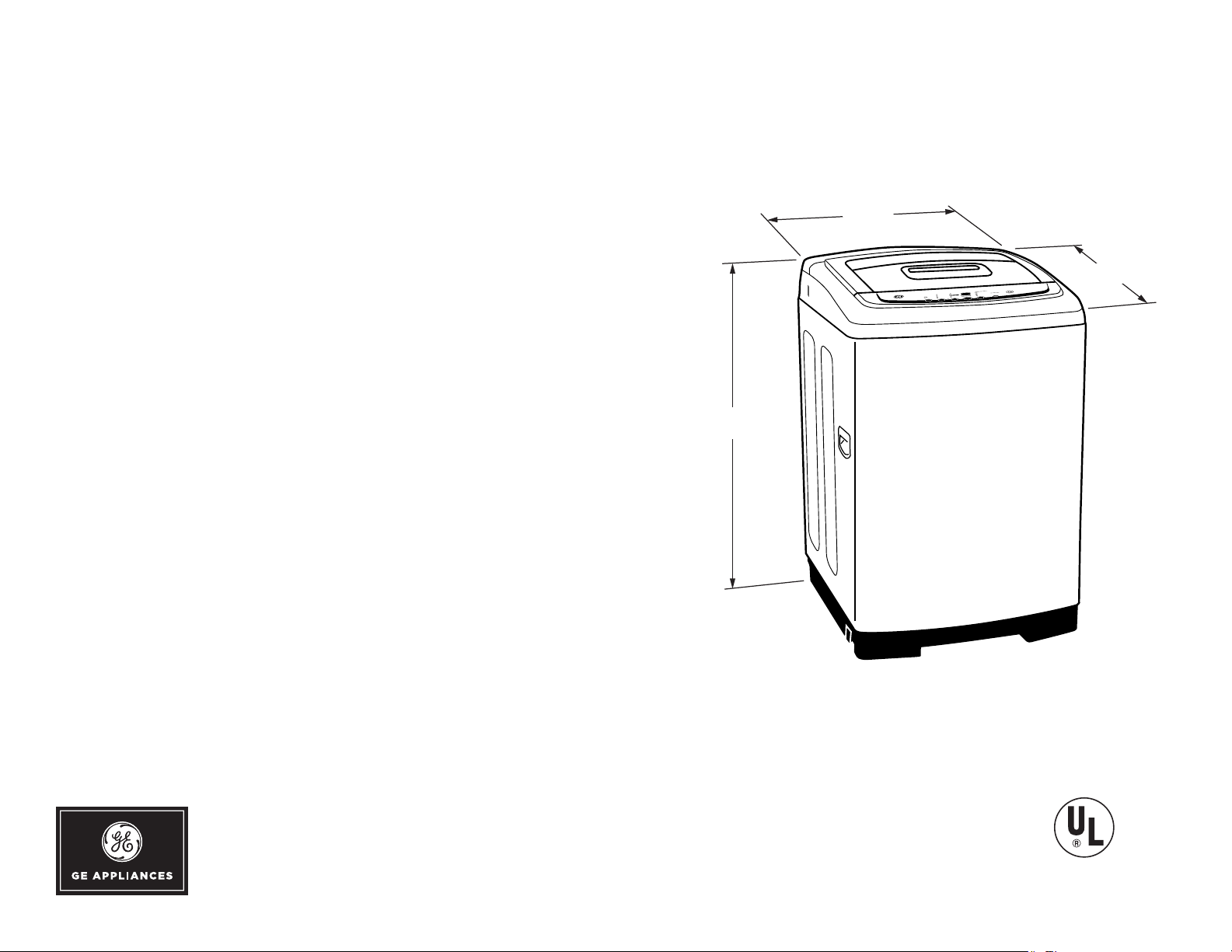
DIMENSIONS AND INSTALLATION INFORMATION (IN INCHES)
CIRCUIT REQUIREMENTS: An individual, properly-
grounded branch circuit, with a three-prong groundingtype receptacle, protected by a 15 or 20 amp circuit
breaker or a time-delay fuse, is required.
ELECTRICAL RATING: 120V; 60Hz
WASH ER NOTE: Washer wall outlet must be located
within 36" of service cord entry. Wall outlet must not be
located behind dryer.
INSTALLATION INFORMATION: For complete
information, see installation instructions packed with your
washer.
37.40"
24"
R
MALL
S
S
ARM
W
OLD
C
MALL
S
XTRA
E
OT
H
OCK
L
HOLD 3 SECS TO
LOCK / UNLOCK
CONTROL
OPTIONS
LOAD
TEMP
DELAY WASH
PIN
1 TO 18 HOURS
LTRA
U
LEAN
C
CYCLES
OWER
P
ENSING
S
OAD
L
OLORS
C
START
HITES
W
OAK
S
PAUSE
ELICATES
D
ARGE
L
ASH
W
ASH
XTRA
E
W
PEED
S
YCLE
UTY
C
D
ARGE
EAVY
L
H
USTOM
INUTES
C
M
ST.
E
EMAINING
R
EDIUM
INSE
M
24 1/2"
For answers to your Monogram, GE Café™ Series, GE Profile™ Series or
GE Appliances product questions, visit our website at geappliances.com
or call GE Answer Center® Service, 800.626.2000.
Listed by
Underwriters
Laboratories
Specif ication Revised 2/18
Page 2
GNW128SSMWW
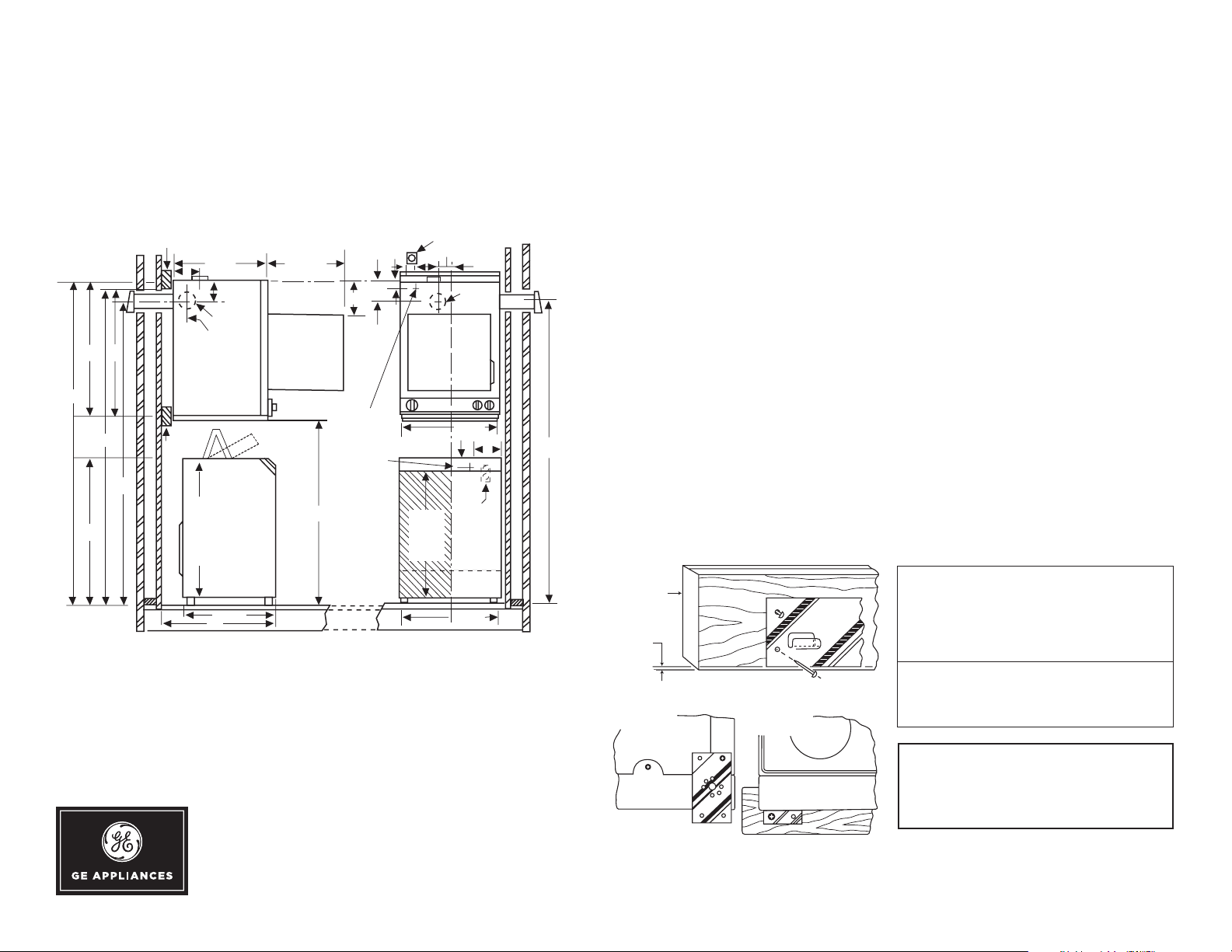
WALL BRACKET
REAR VIEW FRONT VIEW
2 x 4
figure 1
figure 2
1
/8" MAX
prtbl_stnry_bifl_wshr_inst.eps
GE® Space-Saving 2.8 DOE Cu. Ft. Capacity Stationary Washer
with Stainless Steel Basket
DIMENSIONS AND INSTALLATION INFORMATION (IN INCHES)
WMK-35 Wall Kit Installation
33-1/4
79-1/4
78
74-1/8
38
General Information:
The back of the dryer is not accessible for service or maintenance after dryer mounting installation is complete. It is recommended that the dryer be checked and electrical installation completed prior to mounting. For service or maintenance requiring
rear access, the dryer must be removed from the wall.
CAUTION: DISCONNECT ELECTRICAL CURRENT BEFORE INSTALLING OR
SERVICING DRYER.
The electrical outlet must be located above the dryer, or beside the dryer if adequate
dryer-to-wall clearance is available. The outlet must be within three feet on a 240 volt
dryer or a 120 volt dryer from the service cord entry on the rear of the dryer.
2 x 4
32
2 x 4
24-1/2
6
5-1/8
4" Dia.
Exhaust
Both
3-1/8
Sides
DSKS433
DSKS333
WSLP1500
WSLS1500
Standpipe
33" Minimum
If Less Than 33"
Use Syphon
Break Kit
WH49X228
23-7/8
28
120V 20A or
208-240V 30A
3
3-3/4
33" Min.
& Faucets
Standpipe
Rear
Exhaust
23-7/8
1-1/2
120V
15 or 20A
23-1/4
R.H
EXH
6
74-1/8
20" Max.
Opening
46
8
Service
Cord
Entry at
Back of
Appliances
3
5-1/8
For answers to your Monogram, GE Café™ Series, GE Profile™ Series or
GE Appliances product questions, visit our website at geappliances.com
or call GE Answer Center® Service, 800.626.2000.
Dryer Mounting Position
These instructions explain two mounting positions for your 24 inch dryer.
Installation Procedure:
1. Obtain two pieces of 2x4 long enough to span at least two wall studs and the width of the
dr ye r.
2. Locate wall stud center lines. Mark wall stud center lines on t wo pieces of 2x4 in
relationship to position dryer is to be mounted.
3. Referring to dimensional drawing, draw a horizontal reference line (72") from the floor to
locate upper 2x4 support.
4. Position, level and secure upper 2x4 with four 1/4 x 3 inch wood screws. The bottom of
the 2x4 should be positioned on reference line.
5. Referring to dimensional drawing, draw a horizontal reference line 32" down from the
bottom of the upper 2x4 support.
6. Position, level and secure lower 2x4 with two 1/4 x 3 inch wood screws. The center line
of the 2x4 should be positioned on reference line.
7. Referring to figure 1, mount the metal wall bracket 1/8 inch from the bottom of the upper
2x4 support with f ive 1-1/2 inch wood screws.
8. Referring to figure 2, remove one screw from each lower rear corner of dryer and, using
same screws, secure lower brackets (supplied) as shown.
9. Dryer is supplied with exhaust at the top, locate and install outside exhaust duct referring
to the dimensional drawing. For other optional exhaust directions as shown in dimensional
drawing (rear and sides) refer to dr yer installation instruction sheet.
10. Position the dryer on the wall mounting bracket and check that the dryer is plumbed.
11. If the dryer needs plumbing, use some of the twelve washers supplied with the kit as
spacers behind lower brackets of figure 2 and secure the dr yer to the lower 2x4 support
using the remaining 1-1/2 inch wood screws.
This kit consists of the following:
1 Wall mounting bracket
2 Bottom Brackets
6-1/4 x 3 inch wood screws
7-1/4 x 1-1/2 inch wood screws
12 washers
Figure 1
Dryer Requirements
Carefully read and follow individual dryer installation instructions for exhausting requirements.
CAUTION
The 120 volt receptacle on the back
of the 240 volt dryer must not be used
with this wall mount kit.
Figure 2
Specif ication Revised 2/18
Page 3

GNW128SSMWW
GE® Space-Saving 2.8 DOE Cu. Ft. Capacity Stationary Washer
with Stainless Steel Basket
FEATURES AND BENEFITS
Large Capacity – Ample space for clothes for fewer wash loads
Small Footprint – Perfect for small spaces that won't fit a full
size washer
Electronic one-touch controls with LED read-out – Simplify
cycle selection and provide accurate cycle times
8 wash cycles – Handle various fabrics and soils
Four Wash Temperatures – Maximize results by selecting the
perfect temperature for your fabric
Stainless steel basket – It resists rust and won't chip, peel or
snag clothes
Model GNW128SSMWW – White
Specif ication Revised 2/18
 Loading...