

Page 1

Page 1
GE Healthcare
Pre-Installation Manual
Discovery RF180
Discovery RF180
Pre-Installation Manual
5793724-1EN
Revision 6
© 2020 General Electric Company
All rights reserved.
Page 2

Discovery RF180
Pre-Installation Manual
GE Healthcare
5793724-1EN, Rev. 6
Page 2
This page is blank.
Page 3

GE Healthcare
5793724-1EN, Rev. 6
Discovery RF180
Pre-Installation Manual
Page 3
Revision
Hist
ory
Revision Date
Reason for change
01
May 2018
First Version, changes from draft. Base plate torque values and drawing, Wall
stand dimensions, overvoltage image translation, materials and tools review.
Underfloor drawings update, RSVP requirements, information for room layout,
torque values for wall stand.
Critical components data, base plate installation, room height requirements, wifi
detector, details in base plate installation.
02
November 2018
July 2018
Small room packaging, access point, OTS bridge dimension.
September 2018
Base plate installation, dimensions and weights, doors requirements, ducts
dimension, in-room secondary console.
November 2018
Wall stand center of gravity, door sizes, 4” floor example, OTS fixation example,
in-room package, door sizes.
03
April 2019
Par. 4.3.3.2: added grout pad note. Par. 4.3.3.3 note added.
OTS drawings, notes for UPS and MSP for US.
04
July 2019
Floor flatness requirements. Base plate dolly.
05
October 2019
Correction drawing 40833.A page 29.
Addition of Advantech monitor.
Added overall dimensions for monitor suspension
06
March 2020
Par. 5.3.5 service area correction; par. 4.3.1 added a note; added subparagraph to
par. 4.3.3.4 , modified par. 5.2.1 and par. 5.3.1. for Monitor Suspension and OTS
data.
Manufacturer: GENERAL MEDICAL MERATE S.p.A.
Via Partigiani, 25
24068 Seriate (BG) – Italy
Tel. +39 035 45 25 311
Fax +39 035 29 77 87 / 29 95 37
www.gmmspa.com
Distributor: GE Medical Systems, SCS
283, rue de la Miniére,78530 Buc, France
The original version of this publication was drafted in English and will be referred to for any
controversy regarding interpretation of the eventual corresponding versions, translated into other
languages.
The contents of this publication may not be reproduced in any manner with any electronic or
mechanical means. It cannot be distributed in any manner without written authorization issued by
the manufacturer. The manufacturer reserves the right to modify/update this document without
notice.
Page 4

Discovery RF180
Pre-Installation Manual
GE Healthcare
5793724-1EN, Rev. 6
Page 4
Table of Contents
1. General Notes ........................................................................................................................ 7
1.1. Damage in transportation ......................................................................................................... 7
1.2. Certified electrical contractor statement .................................................................................. 7
1.3. Important X-Ray protection....................................................................................................... 8
1.4. Omissions & Errors .................................................................................................................... 8
2. Preface .................................................................................................................................. 9
2.1. Typographic conventions .......................................................................................................... 9
2.2. Warning symbols on the equipment ......................................................................................... 9
3. Introduction ......................................................................................................................... 11
3.1. Objective and Scope of pre-installation .................................................................................. 11
3.2. Responsibilities of the Purchaser ............................................................................................ 11
3.3. What You Will Receive (System Components) ........................................................................ 12
4. Room requirements ............................................................................................................. 15
4.1. Environmental ......................................................................................................................... 15
4.2. Magnetic/Electrical Field Sensitivity and Electromagnetic Emissions .................................... 18
4.3. Structural ................................................................................................................................. 18
4.3.1. Doors requirements ............................................................................................................. 18
4.3.2. Room height requirement ................................................................................................... 23
4.3.3. Floors, Ceilings and Walls .................................................................................................... 25
4.3.3.1. Seismic Requirements .................................................................................................... 25
4.3.3.2. Floor Flatness Requirements .......................................................................................... 25
4.3.3.3. Floor Requirements when using provided Table Floor Anchors .................................... 26
4.3.3.4. Ceiling requirement for OTS and/or Monitor suspension installation ........................... 26
4.3.3.4.1. In-room Ceiling suspension – Single monitor on fixed point ...................................... 27
4.3.3.4.2. Substructure for ceiling fixation of the In-room monitor suspension fixed point ...... 27
4.3.3.4.3. Substructure for ceiling fixation of the In-room monitor suspension fixed point ...... 30
4.3.3.5. Walls ............................................................................................................................... 31
5. System Physical Characteristics ............................................................................................ 32
5.1. Ceiling rails (for OTS and / or Monitor suspension) - option .................................................. 33
5.1.1. Maximum flexion between 2 anchoring points ................................................................... 35
5.1.2. Rail mounting ....................................................................................................................... 36
5.2. Overhead Tube Suspension ..................................................................................................... 37
5.2.1. Packaging ............................................................................................................................. 37
5.2.2. Dimensions .......................................................................................................................... 38
5.3. Monitor suspension (single / double) - option ........................................................................ 41
Page 5

GE Healthcare
5793724-1EN, Rev. 6
Discovery RF180
Pre-Installation Manual
Page 5
5.3.1. Packaging ............................................................................................................................. 41
5.3.2. Dimensions ........................................................................................................................... 42
5.3.3. Packaging – table delivered in one piece ............................................................................. 46
5.3.4. Packaging – table delivered in two pieces ........................................................................... 47
5.3.5. Dimensions ........................................................................................................................... 48
5.4. Base plate installation .............................................................................................................. 53
5.4.1. Use of the under floor installation plate.............................................................................. 55
5.4.2. Use of the over floor installation plate ................................................................................ 56
5.5. Table main control console ...................................................................................................... 60
5.5.1. Packaging ............................................................................................................................. 60
5.5.2. Dimensions ........................................................................................................................... 60
5.6. In-room secondary console (option) ....................................................................................... 61
5.6.1. Packaging ............................................................................................................................. 61
5.6.2. Dimensions ........................................................................................................................... 61
5.7. Generator Cabinet ................................................................................................................... 62
5.7.1. Packaging ............................................................................................................................. 62
5.7.2. Dimensions ........................................................................................................................... 62
5.8. Digital system ........................................................................................................................... 63
5.8.1. Packaging ............................................................................................................................. 63
5.8.2. Dimensions ........................................................................................................................... 64
5.9. Monitor .................................................................................................................................... 65
5.9.1. Packaging ............................................................................................................................. 65
5.9.2. Dimensions ........................................................................................................................... 65
5.10. Monitor Advantech .................................................................................................................. 66
5.10.1. Packaging ............................................................................................................................. 66
5.10.2. Dimensions ........................................................................................................................... 66
5.11. Monitor cart ............................................................................................................................. 67
5.11.1. Packaging ............................................................................................................................. 67
5.11.2. Dimensions ........................................................................................................................... 67
5.12. Wall Stand - option .................................................................................................................. 70
5.12.1. Packaging ............................................................................................................................. 70
5.12.2. Dimensions ........................................................................................................................... 71
5.12.3. Wall Stand Base Plate and Wall Bracket .............................................................................. 73
5.13. Wall stand and Table Layout ................................................................................................... 74
5.14. Detector ................................................................................................................................... 75
5.14.1. Packaging ............................................................................................................................. 75
5.14.2. Dimensions ........................................................................................................................... 76
5.15. Access Point ............................................................................................................................. 77
5.15.1. Packaging ............................................................................................................................. 77
5.15.2. Dimensions ........................................................................................................................... 77
6. Planning Electrical Connections ............................................................................................ 78
6.1. Routing Cables ......................................................................................................................... 78
6.1.1. General ................................................................................................................................. 78
Page 6

Discovery RF180
Pre-Installation Manual
GE Healthcare
5793724-1EN, Rev. 6
Page 6
6.1.2. Conduit................................................................................................................................. 78
6.1.3. Floor Ducts ........................................................................................................................... 78
6.1.4. Power Distribution ............................................................................................................... 78
6.1.5. Emergency Power ................................................................................................................ 78
6.2. Master Interconnect System (MIS) ......................................................................................... 79
6.3. Hospital Network Connections ................................................................................................ 79
6.3.1. Remote services broadband pre-installation requirements for Europe ............................. 79
6.3.2. RSVP Network requirements ............................................................................................... 79
6.3.3. DICOM hospital Network ..................................................................................................... 80
7. Laying Out the Room ............................................................................................................ 81
7.1. Considerations ......................................................................................................................... 81
7.1.1. Privacy and security ............................................................................................................. 81
7.1.2. Radiation Protection ............................................................................................................ 81
7.1.3. Service Access ...................................................................................................................... 81
7.1.4. Clinical Access ...................................................................................................................... 81
7.1.5. Peripheral Equipment .......................................................................................................... 82
7.2. Typical Room Layout ............................................................................................................... 83
8. System Facility Power and Grounds ...................................................................................... 89
8.1. Introduction ............................................................................................................................. 89
8.2. Electrical Requirements ........................................................................................................... 89
8.2.1. Power quality and System Power Specifications ................................................................. 89
8.2.2. Table Electrical requirements .............................................................................................. 95
8.2.3. Generator Electrical Requirements ..................................................................................... 96
8.3. UPS Electrical Requirements ................................................................................................... 97
8.4. Electrical Grounds .................................................................................................................... 98
9. Materials and Tools ............................................................................................................ 102
10. System Cable Information .................................................................................................. 103
Page 7

GE Healthcare
5793724-1EN, Rev. 6
Discovery RF180
Pre-Installation Manual
Page 7
1. General Notes
Important note
THIS SERVICE MANUAL IS AVAILABLE IN ENGLISH ONLY.
IF A CUSTOMER’S SERVICE PROVIDER REQUIRES A LANGUAGE OTHER THAN ENGLISH, IT IS THE
CUSTOMER’S RESPONSIBILITY TO PROVIDE TRANSLATION SERVICES.
DO NOT ATTEMPT TO SERVICE THE EQUIPMENT UNLESS THIS SERVICE MANUAL HAS BEEN
CONSULTED AND UNDERSTOOD.
FAILURE TO HEED THIS WARNING MAY RESULT IN INJURY TO THE SERVICE PROVIDER, OPERATOR OR
PATIENT FROM ELECTRIC SHOCK, MECHANICAL OR OTHER HAZARDS.
1.1. Damage in transportation
All packages should be closely examined at time of delivery. If damage is apparent, write “Damage in
Shipment” on ALL copies of the freight or express bill BEFORE delivery is accepted or “signed for” by a
distributor representative or hospital receiving agent. Whether noted or concealed, damage MUST
be reported to the carrier immediately upon discovery, or in any event, within 14 days after receipt,
and the contents and containers held for inspection by the carrier.
A transportation company will not pay a claim for damage if an inspection is not requested within this
14 day period. Call the distributor service department, immediately after damage is found. At this
time be ready to supply name of carrier, delivery date, consignee name, freight or express bill
number, item damaged and extent of damage.
1.2. Certified electrical contractor statement
All electrical Installations that are preliminary to equipment positioning shall be performed by
licensed electrical contractors. In addition, electrical feeds into the Power Distribution Unit shall be
performed by licensed electrical contractors. Other connections between pieces of electrical
equipment, calibrations and testing shall be performed by qualified Systems personnel. The products
involved (and the accompanying electrical installations) are highly sophisticated, and special
engineering competence is required.
In performing all electrical work on these products, the distributor shall use their own specifically
trained field engineers. All of distributor’s electrical work on these products shall comply with the
requirements of the applicable electrical codes.
The purchaser of the equipment shall only use qualified personnel (i.e., distributor’s field engineers,
personnel of third party service companies with equivalent training, or licensed electricians) to
perform electrical servicing on the equipment.
Page 8

Discovery RF180
Pre-Installation Manual
GE Healthcare
5793724-1EN, Rev. 6
Page 8
1.3. Important X-Ray protection
X-RAY EQUIPMENT AND DEVICES CAN BE DANGEROUS FOR THE HEALTH OF BOTH
PATIENTS AND OPERATORS UNLESS PROPER SAFETY MEASURES ARE STRICTLY OBSERVED.
Although this equipment was designed and manufactured according to the most up-to-date safety
standards, the source of X-rays is always dangerous when the operator is not properly qualified or
trained. Excessive exposure to X-rays damages the human body.
Therefore, all the necessary precautions must be taken to prevent unauthorized or unskilled
personnel from operating this equipment, thus jeopardizing themselves and other people. Do not use
the equipment if you have not received appropriate training in the correct and safe use of the
equipment itself by the manufacturer or any of his appointed instructors.
Before executing any operation, the persons qualified and authorized to operate this equipment
must be informed about the protection and safety measures established by the International
Committee for Radiological Protection, as well as any other relevant national Standards.
1.4. Omissions & Errors
The manufacturer declines all responsibility with regard to the proper functioning of the equipment,
should the installation or the maintenance of it be executed by unauthorized personnel.
The X-ray system’s installation instructions are included in the service manual, which is a separate
item from the Operator’s manual.
Page 9

GE Healthcare
5793724-1EN, Rev. 6
Discovery RF180
Pre-Installation Manual
Page 9
2. Preface
2.1. Typographic conventions
In order to facilitate the reading of the manual, different styles and types were used.
The text identified by bullets indicates:
• Instructions to be executed according to the sequence specified.
The text in italics inside a frame indicates:
Useful supplementary information for the technician.
The following icons are also used:
Important information
It is advisable that extra attention be paid in reading the topics identified with
this symbol.
WARNING
The topics identified with this icon regard aspects of safety for the patient
and/or operator.
2.2. Warning symbols on the equipment
Warning symbol that indicates potential generic danger for the equipment or
the operator. It invites the operator to check the equipment documentation for
further details.
Warning symbol that invites operators to follow the instructions for using the
device on which the symbol itself is applied.
Hazard symbol that indicates X-ray radiation exposure.
Warning symbol that indicates electrical components which are sensitive to
electrostatic discharge.
Page 10

Discovery RF180
Pre-Installation Manual
GE Healthcare
5793724-1EN, Rev. 6
Page 10
Warning symbol that indicates live electrical parts with a possible risk of electric
shock.
Warning symbol that indicates that fingers may be crushed.
Symbol of protective earth (ground).
“ON” symbol (power).
“OFF” symbol (power).
“ON” / “OFF” symbol (push-push).
Symbol of applied part B type.
Symbol of filtration.
Symbol that indicates electrical and electronic components which must be
collected separately.
Fluoroscopy and radiography foot pedal connector fitting
The screws labelled with ETS symbol (Essential To Safety) are involved in safety
during installation or parts replacement.
The technician is asked to label with a red marker each of these screws.
Page 11

GE Healthcare
5793724-1EN, Rev. 6
Discovery RF180
Pre-Installation Manual
Page 11
3. Introduction
3.1. Objective and Scope of pre-installation
This document is intended as a guide and informational resource for planning and properly preparing
a location for the system installation. This document is intended to assist the customer and installer
in properly preparing a site for product installation.
3.2. Responsibilities of the Purchaser
The purchaser is responsible for the completion of the “pre-installation” requirements. This includes
the procurement and installation of all required materials and services to get the room ready for the
product installation.
This responsibility includes providing:
• A clean and safe work environment for the product installation (finished floor, ceiling, walls,
and proper room lighting).
• A location suitable for the product installation. See Chapter 2 - Suite/Room Requirements.
• Suitable support structures in the floor, walls, or ceiling necessary for the mounting of the
product and/or its components. Installation of conduit ducts and/or raceways necessary to
route cables safely. System Physical Characteristics and Chapter 6 – Planning Electrical
Connections.
Note: Unistrut / halfen / equivalent rails and means necessary to anchor of the Mavig Substructure
and the Mavig mounting plate for the “in room ceiling suspension on fixed point” (rails, anchors,
bolts, screws, etc.) are not delivered with the kit and should be provided and designed under
customer responsibility.
• Electrical power and grounds of specified quality and reliability. See Chapter 8 – System
Facility Power and Grounds.
• Electrical power of the required voltage, including an emergency-off safety switch in the
room. Power and ground cables to the PDU.
• Properly installed and sized junction boxes, including covers and fittings at locations
required and called out in the architectural drawings.
Page 12

Discovery RF180
Pre-Installation Manual
GE Healthcare
5793724-1EN, Rev. 6
Page 12
3.3. What You Will Receive (System Components)
Table assembly with table cabinet
Table main control console
Digital system (with UPS*)
*UPS provided by GMM except for US
(specific version for US available with CAT Number S13411PS)
H.V. Indico IQ Generator
Single / Double monitor suspension (option)
S13441MM – Single Monitor Suspension
S13441RF – Radshield on fixed point (option)
Page 13
GE Healthcare
5793724-1EN, Rev. 6
Discovery RF180
Pre-Installation Manual
Page 13
S13441MF – Substructure for ceiling fixation of
the in-room monitor suspension fixed point. In
case of installation on concrete ceiling preferred.
S13441MP – Mounting Plate for ceiling fixation
of the In-room monitor suspension fixed point
(including the items 1, 2, 3 and 4) In case of
installation on Unistrut / Halfen / equivalent
rails preferred.
OTS (option)
Wall stand (option)
In-room secondary Console (option)
Single / Double monitor cart (option)
Page 14

Discovery RF180
Pre-Installation Manual
GE Healthcare
5793724-1EN, Rev. 6
Page 14
Product Name
Catalog Number
Discovery RF180 system
S13441RS
Digital system (RF4343 detector + Monitor)
S13431AB
Digital system (RF4343FL detector + Monitor) (not for US)
S13431AC
DIN Monitor (Option)
S13441GM
RAD Wifi detector (Gadox) 3543EZ and access point (not for US)
S13431FG
RAD Wifi detector (CSI) 3543EZ and access point
S13431FH
RAD Wifi detector (CSI) 2430EZ and access point
S13431FK
High Voltage Generator (65kW – 1 tube) (not for US)
S13431BR
High Voltage Generator (80kW – 1 tube) (not for US)
S13431BT
High Voltage Generator (65kW – 2 tube)
S13431E
High Voltage Generator (80kW – 2 tube)
S13431EA
Single Monitor Suspension
Radshield on fixed point (option)
S13441MM
S13441RF
Substructure for ceiling fixation of the in-room monitor suspension
fixed point.
S13441MF
Mounting Plate for ceiling fixation of the In-room monitor
suspension fixed point.
S13441MP
(Option)
Single Monitor Ceiling Suspension including Bridge & Carriage
S13431NG
(Option)
Dual Monitor Ceiling Suspension including Bridge & Carriage
S13431NH
Radshield for ceiling suspension (Option)
S13441SR
In-Room single monitor on Cart (option)
S13431DG
UPS unit (Version provided by GMM except for US)
S13441PE
Wall Stand (option) Tilting Left hand (not for US)
S13441TL
Wall Stand (option) Tilting Right hand (not for US)
S13441TR
Wall Stand (option) NON tilting Left hand
S13441WL
Wall Stand (option) NON tilting Right hand
S13441WR
Overhead Tube Suspension OTS (option)
S13411EB
In-room secondary console (option)
S13441RC
UPS (US SYSTEM ONLY not provided by GMM)
S13441PS
MDP (US SYSTEM ONLY not provided by GMM)
S13411MD
Page 15

GE Healthcare
5793724-1EN, Rev. 6
Discovery RF180
Pre-Installation Manual
Page 15
4. Room requirements
4.1. Environmental
The unit has been designed to operate in a room respecting the following environmental conditions:
Device
Storage
temperature
Operating
Temperature
Digital system (PU included)
-20 … +60°C
+10 … +40 °C
Detector Pixium 4343FL
-25 … +55 °C
+15 … +35 °C
Detector Pixium RF4343
-25 … +55 °C
+15 … +35 °C
Detector Pixium 3543EZ
-10 … +55 °C
+15 … +35 °C
Detector Pixium 2430EZ
-10 … +55 °C
+15 … +35 °C
Generator
-20 … +50 °C
+10 … +40 °C
Table
-20 … +60 °C
+15 … +40 °C
Monitor (Eizo)
-20 … +60 °C
+5 … +35 °C
Monitor (Advantech)
-20 … +60 °C
+0 … +40 °C
UPS (not valid for US)
-15 … +50 °C
+0 … +40 °C
Monitor suspension (option)
-20 … +70 °C
+10 … +40 °C
OTS (option)
-20 … +60 °C
+15 … +40 °C
Wall Stand
-20 … +70 °C
+10 … +40 °C
Wall Stand (tilting)
-20 … +70 °C
+10 … +40 °C
Vacutec DAP (Dose Area Product)
-20 … +60 °C
+10 … +40 °C
Access Point
-20 … +65 °C
+0 … +40 °C
UPS (US ONLY, not provided by GMM)
-25 … +55 °C
+0 … +40 °C
MDP (US ONLY, not provided by GMM)
-25 … +70 °C
+0 … +40 °C
Device
Storage
Humidity
Operating
Humidity
(non cond.)
Digital system
(PU included)
10 … 90%
30 … 75%
Detector Pixium 4343FL
5 … 95%
20 … 75%
Detector Pixium RF4343
5 … 95%
20 … 75%
Detector Pixium 3543EZ
5 … 95%
20 … 80%
Detector Pixium 2430EZ
5 … 95%
20 … 80%
Generator
5 … 85%
20 … 80%
Table
10 … 80%
20 … 80%
Monitor (Eizo)
10 … 90%
20 … 80%
Monitor (Advantech)
5 … 90%
Ta = 40 °C, 90% RH
UPS (not valid for US)
10 … 90%
0 … 95%
Monitor suspension (option)
10 … 95%
20 … 75%
OTS (option)
10 … 80%
20 … 80%
Wall Stand
10 … 90%
30 … 75%
Page 16

Discovery RF180
Pre-Installation Manual
GE Healthcare
5793724-1EN, Rev. 6
Page 16
Device
Storage
Humidity
Operating
Humidity
(non cond.)
Wall Stand (tilting)
10 … 90%
30 … 75%
Vacutec DAP (Dose Area Product)
10 … 80%
10 … 80%
Access Point
5 … 95%
10 … 90%
UPS (US ONLY, not provided by GMM)
0 … 95%
0 … 96%
MDP (US ONLY, not provided by GMM)
5 … 95%
0 … 95%
Device
Storage
Pressure
Operating
Pressure
Digital system
(PU included)
700 … 1060hPa
700 … 1060hPa
Detector Pixium 4343FL
500 … 1060hPa
700 … 1060hPa
Detector Pixium RF4343
500 … 1060hPa
700 … 1060hPa
Detector Pixium 3543EZ
500 … 1100hPa
700 … 1100hPa
Detector Pixium 2430EZ
500 … 1100hPa
700 … 1100hPa
Generator
700 … 1060hPa
700 … 1060hPa
Table
500 … 1060hPa
500 … 1060hPa
Monitor (Eizo)
200 … 1060hPa
700 … 1060hPa
Monitor (Advantech)
500 … 1013hPa
500 … 1013hPa
Monitor suspension (option)
500 … 1060hPa
700 … 1060hPa
OTS (option)
500 … 1060hPa
700 … 1060hPa
Wall Stand
700 … 1060hPa
700 … 1060hPa
Wall Stand (tilting)
700 … 1060hPa
700 … 1060hPa
Vacutec DAP (Dose Area Product)
800 … 1060hPa
800 … 1060hPa
UPS (US ONLY, not provided by GMM)
700 … 1060hPa
700 … 1060hPa
MDP (US ONLY, not provided by GMM)
794 … 1060hPa
794 … 1060hPa
Device
Supply
Voltage
Mains
Frequency
Momentary
Current
Operating
Current
Operating
Power
Digital system
(PU and detector
included)
230Vac
10 %
50/60 Hz
1.5A
1.3A
350 VA
Generator IQ
(65kW)
400Vac
3-phase
10 %
50/60 Hz
2 %
135A/phase
---
300 VA
stand-by
95 kVA
peak
Page 17

GE Healthcare
5793724-1EN, Rev. 6
Discovery RF180
Pre-Installation Manual
Page 17
Device
Supply
Voltage
Mains
Frequency
Momentary
Current
Operating
Current
Operating
Power
480Vac
3-phase
10 %
50/60 Hz
2 %
110A/phase
---
300 VA
stand-by
95 kVA
peak
Generator IQ
(80kW)
400Vac
3-phase
10 %
50/60 Hz
2 %
168A/phase
---
300 VA
stand-by
115 kVA
peak
480Vac
3-phase
10 %
50/60 Hz
2 %
140A/phase
---
300 VA
stand-by
115 kVA
peak
Monitor
(for all the
devices)
200Vac
240Vac
50/60 Hz
---
0.5A
21 W typ.
57 W max.
Monitor
(Advantech)
100 – 240 Vac
(power supply)
50/60 Hz
---
---
65 W max
OTS
220/230/240Vac
(10%)
Single phase
50/60 Hz
3 %
---
---
100 VA
stand-by
1370 VA
peak
Table
400V
3-phase
10 %
50/60 Hz
2 %
3.5A phase
N.A.
600 VA
stand-by
4000 VA
peak
Device
Heat dissipation
W
BTU/hour
Digital system (PU and detector included)
320
1092
Generator (IQ)
22 (standby)
1026 (during fluoro)
75 (standby)
3500 (during fluoro)
UPS (average)
(not valid for US)
50
171
Monitor (single)
57
149
Monitor (single Advantech)
65 max
222 max
OTS (option)
350
1190
Table
700 (average)
2388 (average)
Wall Stand
N.A.
N.A.
System noise in stand-by: < 45 dB
System noise in working conditions: < 65 dB
Page 18

Discovery RF180
Pre-Installation Manual
GE Healthcare
5793724-1EN, Rev. 6
Page 18
4.2. Magnetic/Electrical Field Sensitivity and Electromagnetic Emissions
All the products or components of the system meet EMI and EMC requirements and IEC 60601-1-2
(International). Because X-ray equipment produces radiation, special precautions may need to be
taken or special site modifications may be required. This manual does not make recommendations
regarding radiation protection. It is the purchaser’s responsibility to consult a radiation physicist for
advice on radiation protection in X-ray rooms.
4.3. Structural
4.3.1. Doors requirements
Make reference to the following examples pictures.
Component
Minimum Doors size requirements
(using provided dollies, pallets, etc)
Minimum
corridor depth
Height
Width
Table delivered in
cm
inches
cm
inches
One piece
Two pieces
Table
185
73
120
47.2
>= 120 cm
(47.2 inches)
>= 115 cm
(45.3 inches)
117
46
>= 122 cm
(48 inches)
>= 117 cm
(46 inches)
102
40.2
>=160 cm
(63 inches)
>= 130 cm
(51.2 inches)
95
37.4
NO
>= 135 cm
(53.1 inches)
In case the doorway is between 102 - 105 cm, be aware that the Spot Film Device (SFD) has to be
removed temporarily from the table beam during maneuvered thru the doorway. Refer to the
Installation Manual, section 10.2.1. (P/N 5793725-1EN).
Component
Minimum Doors size requirements
(using provided dollies, pallets, etc)
Minimum
corridor depth
Height
Width
cm
inches
cm
inches
inches
cm
Overhead Tube
Suspension
(and Monitor
suspension
transversal
bridge)
180
71
90
35
>= 102.4
>= 260
140
55
>= 71
>= 180
Generator
132
52
71
28
---
---
Digital system
---
---
80
31.5
---
---
Wall stand
---
---
80
31.5
---
---
Page 19

GE Healthcare
5793724-1EN, Rev. 6
Discovery RF180
Pre-Installation Manual
Page 19
Table – delivered in one piece
The unit can be shipped in a whole lot that can be maneuvered through a 102 – 120-cm doorway.
In case of 102cm doorway, the table main frame will require about 1.60 m minimum hallway width to
allow negotiating turns.
In case of 120-cm doorway the table main frame will require about 1.20-mt. minimum hallway width
to allow negotiating turns.
(Measure in cm)
Page 20
Discovery RF180
Pre-Installation Manual
GE Healthcare
5793724-1EN, Rev. 6
Page 20
Table – delivered in two pieces
The unit can be divided into few assemblies, in most cases the two major assemblies could be
maneuvered through a 102-cm doorway.
The most limiting item is the table main frame that will require about 1.30-mt. minimum hallway
width to allow negotiating turns.
Measure in cm.
In case of 120cm doorway, the table main frame will require about 1.15 m minimum hallway width to
allow negotiating turns.
Measure in cm.
In case the unit is shipped into two pieces, please find sizes and weight in the following pictures:
Page 21

GE Healthcare
5793724-1EN, Rev. 6
Discovery RF180
Pre-Installation Manual
Page 21
Measures in mm.
Measures in mm.
Weight = 680 kg
1630
Page 22

Discovery RF180
Pre-Installation Manual
GE Healthcare
5793724-1EN, Rev. 6
Page 22
OTS
The same constraints can be considered valid also for monitor suspension transversal bridge.
Measures in mm
Measures in mm
Page 23

GE Healthcare
5793724-1EN, Rev. 6
Discovery RF180
Pre-Installation Manual
Page 23
4.3.2. Room height requirement
The minimum room height for the table must take into consideration the most protruding object
from the ceiling that is in the system area (for example the rails for OTS).
The minimum room height for the table is 260 cm (103”). In any case, the recommended room height
to move the system with software limitations is 300 cm (118”).
However, for a system with OTS and wall stand, full range of wall stand use is achieved with a ceiling
height of 292 cm . A higher height will limit the lower end of the useful travel range of the wall stand.
For all OTS dimensions and travels make reference to par. 5.2, page 37.
Parameter value
Minimum ceiling
height [cm]
Table constrains
Value of the ceiling
height.
From 260 to 269
WARNING! Tilting limitation! It is not possible to reach
a complete tilting. The tilting angulation will be limited
to a value less than +90° and -90°.
It is not possible to reach the maximum focal distance
and the maximum table elevation together. It means
that if you need the maximum focal distance you
cannot use the maximum table elevation and vice
versa.
From 270 to 299
A complete table tilting is always possible but with
some software limitations.
It means that during the tilting movement the focal
distance is automatically reduced. The tilting
movement is automatically stopped if the longitudinal
position of the column introduces a collision risk with
the ceiling. In this case it is necessary to manually
move the column to place it in the middle of the
longitudinal area.
Because the maximum table height is 295 cm when it
is in horizontal position, it is not possible to reach the
maximum focal distance and the maximum table
elevation at the same time.
The recommended room height is 300 cm.
NOTE: IF AN OTS KALOS OTS HAVE TO BE INSTALLED
IN THE ROOM WITH FIXATION RAILS ABOVE THE
RF180 SYSTEM, THE MIN CEILING HEIGHT TO HAVE
THE COMPLETE TABLE TILTING IS 293cm (9.6 feet).
From 300 to 319
As in the previous condition a complete table tilting is
always possible with software limitations.
With this ceiling height it is possible tilt the table with
the column in the middle of the longitudinal area but
with the maximum focal distance and maximum table
elevation.
Page 24

Discovery RF180
Pre-Installation Manual
GE Healthcare
5793724-1EN, Rev. 6
Page 24
Parameter value
Minimum ceiling
height [cm]
Table constrains
From 320 to 359
With the minimal focal distance, it is always possible
to tilt the table with the column in any longitudinal
position.
From 360 to ∞
Table without limited movements.
It is possible to tilt the table in every condition,
maximum elevation and focal distance with the
column in every longitudinal position.
Minimum ceiling
height [cm]
Wall Stand constrains
Tilting wall stand
From 260 to 264
Wall Stand Arm Support option not applicable
From 265 to ∞
Wall Stand Arm Support option applicable
Not tilting wall stand
From 240 to 279
Wall Stand Arm Support option not applicable
From 280 to ∞
Wall Stand Arm Support option applicable
Minimum ceiling
height [cm]
Monitor suspension
From 260 to 320
Complete vertical travel is possible
From 320 to ∞
For rooms higher than 320 cm / 126 in, we strongly
suggest a ceiling construction between structural
ceiling and vertical column.
Minimum ceiling
height [cm]
Overhead Tube Suspension constrains
From 260 to 292
The vertical travel must be manually reduced because
the ceiling height is not enough.
From 292 to 300
OTS can use the complete vertical travel.
From 300 to ∞
OTS with limited lower end of the useful travel range of
the wall stand is possible.
Page 25

GE Healthcare
5793724-1EN, Rev. 6
Discovery RF180
Pre-Installation Manual
Page 25
4.3.3. Floors, Ceilings and Walls
4.3.3.1. Seismic Requirements
Seismic requirements are determined and specified by the hospital structural engineer of record and
approved by the specific state or country agency.
4.3.3.2. Floor Flatness Requirements
See below figure for graphical definition of “flatness”. To insure a sufficient contact surface with the
floor, the below shaded region under the base plate must be within 1.5mm or 1/16” flatness (i.e. no
local concave or convex regions >1.5mm from flat). The critical region of flatness is:
- 1000mm wide and centered longitudinally under base
- 600mm deep against the rear of the base plate
Outside this region, shims may be used along the perimeter of the base plate to improve surface
contact.
Floor Levelness Requirement
See below figure for graphical definition of “levelness”. Discovery RF180 requires a floor levelness of
6mm or ¼”: the maximum height difference between any two points on the floor under the baseplate
with respect to perfect level measured via self-leveling laser, may not exceed 6mm or ¼”.
Page 26

Discovery RF180
Pre-Installation Manual
GE Healthcare
5793724-1EN, Rev. 6
Page 26
Grout Pad Concession
In case of any violations of the above flatness/levelness requirements, it is STRONGLY recommended
the floor be leveled by the contractor to insure proper contact of base plate. This will greatly improve
the overall install quality and timing.
In the event this is not possible, a concession will be required. Self-levelling products may be an
option, including:
• Keratech Eco Flex (Kerakoll S.p.A.)
• “Ardex K15”, available at GE, orderable with SCAT S0915SW – reference installation
procedure GE DOC2242533
• Henry 565 which may be locally available
However, a concession will be required to review the specifics of the room and whether grout will be
a viable solution.
Strictly follow the instructions provided in the products’ technical data sheets.
It is recommended to entrust this job to field professionals who will be able to suitably prepare the
floor surface and to set up the containment structures for the solidification of these materials.
Upon solidifying, these products can usually be drilled with low speed drills until reaching the slab or
by performing a sequence of drilling, starting from smaller diameter drills and increasing up to the
diameter desired. Please ask the permission to the installation responsible team before drilling.
4.3.3.3. Floor Requirements when using provided Table Floor Anchors
The maximum pullout force per provided anchor was calculated assuming:
• A regular weight concrete having a minimum of 28-day compression, class min C20/C25
(UNI EN 206-1).
• Concrete thickness should be at least 200mm. For 100 and 140mm thickness refer to 5.4.2.
• Anchors installed to the required hole depth of 130mm. Refer to 5.4.2 for others examples.
• Center of anchor hole to concrete edge distance 106.5 mm (valid for all the examples).
Make sure to obtain concrete compression strength data before using floor anchors.
NOTE: make reference to par. 5.4.2 for 140mm or 100mm concrete thickness examples.
4.3.3.4. Ceiling requirement for OTS and/or Monitor suspension installation
The construction and load capability of the ceiling must be sufficient for the installation of the unit.
It is the responsibility of the customer or structural engineer to evaluate the best fixation system to
be used for the ceiling rails/mounting systems as described in the following layout example under
consideration of the options to be installed.
A good ceiling levelness is required. For OTS, a maximum of 7 mm height displacement along the
ceiling longitudinal rails is allowed and can be corrected with the use of shims to ensure the rails are
as close to perfect level as possible.
Page 27

GE Healthcare
5793724-1EN, Rev. 6
Discovery RF180
Pre-Installation Manual
Page 27
Aluminum rails support the Overhead Tube Suspension and the in-room LCD Monitor bridge used in
X-ray rooms.
Monitor Suspension, that will be included:
measured in mm
The installation of the single/double Monitor option is to be installed to the upper mounting point of
the suspension.
An optional Radshield has to be mounted to the lower mounting point.
Reference - For details on ceiling requirements for stationary rails, refer to Chapter 5 System Physical
Characteristics.
4.3.3.4.1. In-room Ceiling suspension – Single monitor on fixed point
The In-room Ceiling monitor suspension on fixed point can be attached to the solid ceiling using one
of the two following options:
- attached to the substructure: the substructure is used as the bridging element between the
solid ceiling and the ceiling flange (top plate of the monitor suspension). The means required
for the fixation of the suspension to the substructure are delivered with the substructure.
- attached to the mounting plate: the mounting plate is installed to the hardware defined by
the structural engineer (It could be Unistrut / Halfen or equivalent rails). The ceiling flange
(top plate of the monitor suspension) is fixed to the mounting plate. The means required for
the fixation of the suspension to the mounting plate are delivered with the substructure.
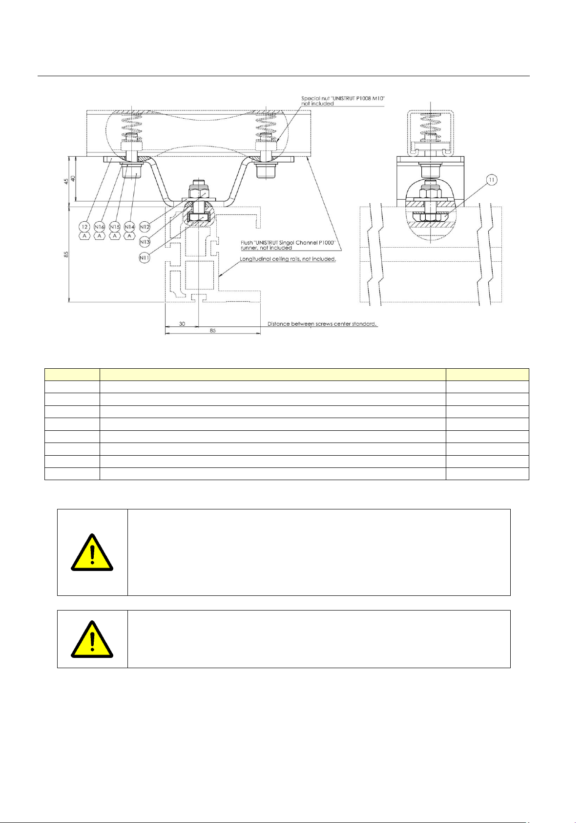
4.3.3.4.2. Substructure for ceiling fixation of the In-room monitor suspension fixed point
The used mounting of the Monitor Suspension can be realized in three different ways:
- Fixed Monitor Suspension, direct to the ceiling
Standard Installation of MAVIGs Portegra2 System. Refer to the GE DOC 5849374-1EN for
MAVIGs Portegra2 Installation Manual - POR03Oxx (where xx stands for the latest revision,
12 or higher).
Page 28

Discovery RF180
Pre-Installation Manual
GE Healthcare
5793724-1EN, Rev. 6
Page 28
- Fixed Monitor Suspension to the ceiling with Substructure.
The Substructure is mandatory to install the MAVIG suspension with fixed point directly to
the solid ceiling for Non-seismic Zones. For Seismic Zone installations, refer to Structural
Engineer for appropriate design of the structure for installing the MAVIG suspension system.
For standard site configurations, the distance between the ceiling and the ceiling flange
should be in a range of minimum 100 mm and maximum 626 mm.
If the distance between the ceiling and the ceiling flange is more than 626 mm, Long
variation of the Substructure for could be proposed by MAVIG.
Substructure (schematic)
1. Ceiling
2. Ceiling Plate - weight approx.4,9 kg
3. Threaded rods (8 pieces), M16 - 8.8,
length 495mm
4. Middle Plate - weight approx. 4,5 kg
5. Threaded rods (4 pieces), M16 - 8.8,
length 195mm
6. Interface Plate – weight approx. 2,3 kg
7. False Ceiling (not part of Delivery)
Page 29

GE Healthcare
5793724-1EN, Rev. 6
Discovery RF180
Pre-Installation Manual
Page 29
Substructure Ceiling Plate for installation to the ceiling
The Substructure must be fastened to the ceiling using 8 suitable screws.
These screws must be dimensioned according to the conditions of the ceiling and provided by the
customer and must be checked by the structural engineer.
The Substructure ceiling plate must be seated flush to the ceiling in order to ensure optimum load
distribution.
Bolt Specifications:
Appropriate ceiling anchoring must withstand a maximum load of:
Normal Force: 1182,3 N
Momentum: 1148.51 Nm
The maximum pullout force shall be calculated in accordance with local building codes and it is part
of structural analysis done by customer.
Refer to GE Doc: 5849373-1-EN for MAVIGs Substructure Installation Manual - DBF02Oxx (where xx
stands for the latest revision, 04 or higher)
Page 30

Discovery RF180
Pre-Installation Manual
GE Healthcare
5793724-1EN, Rev. 6
Page 30
4.3.3.4.3. Substructure for ceiling fixation of the In-room monitor suspension fixed point
The Mounting plate is mandatory to install the MAVIG suspension with fixed point to an existing
Unistrut / Halfen or equivalent rails for Non-seismic Zones. For Seismic Zone installations, refer to
Structural Engineer for appropriate design of the structure for installing the MAVIG suspension
system.
Mounting Plate for rails (Unistrut or Halfen)
Refer to the GE Doc: 5849374-1EN for MAVIGs Portegra2 Installation Manual - POR03Oxx (where xx
stands for the latest revision, 12 or higher).
Room layout
MAXIMUM SUGGESTED DISTANCE FROM FLOOR 3100mm
Page 31

GE Healthcare
5793724-1EN, Rev. 6
Discovery RF180
Pre-Installation Manual
Page 31
Suggested position for Mavig 360° column installation (fixed on ceiling), in order to cover all clinical
scenario with no limitation of use.
Warning: the operator is responsible for the position and potential collision of the suspension in
relation to the position of the table. There are not safety interlocks which avoid table movements
depending from suspension position.
4.3.3.5. Walls
Precautionary measures have been taken to prevent scatter radiation from entering other rooms
and/or hallways and that all exposed walls are lead-lined.
In particular the hospital physicians should approve the room layout before the installation starts.
Under normal conditions, the wall at the installation site must be capable of supporting, minimally, a
110 lb. (490 N) pull from the wall at each anchor bolt.
Page 32

Discovery RF180
Pre-Installation Manual
GE Healthcare
5793724-1EN, Rev. 6
Page 32
5. System Physical Characteristics
Refer to this section for the dimensional drawings of the components
Note: Drawings are not to scale. Dimensions are called out on each drawing
Component
Width
Height
Depth
Weight
Mounting comments
Table Assembly
246-414 cm
177-295cm
(not tilted)
201-221cm
1380kg
Mount on floor
Table main control
console
44cm
19cm
27cm
8kg
Placed on desk
Generator cabinet
51cm
106cm
41cm
91kg
Mount on floor
118kg packed
Digital system
56.8cm
90.1cm
73.7cm
110kg
Mount on wheels
UPS (not valid for US)
25.5cm
42.5cm
36cm
33,6kg
Mount on floor
Monitor
(for all the devices)
55.7cm
36.1cm
21.6cm
40.1cm (1)
6.6 kg
Mount on desk
Monitor
(Advantech)
57.8cm
40.3cm
68cm
9 kg (3)
---
Monitor suspension
mounting Plate
74cm
40cm
1.2cm
22kg
Mount to rails /
directly to the ceiling
Monitor suspension
substructure
62.6cm
30cm
30cm
22kg
Mount on ceiling
Single Monitor
suspension (2)
441cm
205cm
301cm
85 kg (4)
Monitor not
included
Double Monitor
suspension (2)
441cm
205cm
301cm
86 kg (4)
Monitors not
included
Overhead Tube
Suspension bridge
included (2)
441cm
291cm
301cm
300 kg
+ 78 kg
Mount on ceiling
rails
Wall Stand not
tilting
62cm
225cm
46cm
171kg
Mount on floor and
to wall
Wall Stand tilting
62cm
225cm
72cm max
200kg
Mount on floor and
to wall
UPS (ONLY FOR US)
203.2mm
(8.4inches)
330.2mm
(13.6inches)
406.4mm
(16.2inches)
34.9Kg
(77.2lbs)
(ONLY FOR US, NOT
PROVIDED BY GMM)
MDP (ONLY FOR US)
637.5mm
(25inches)
889mm
(35inches)
254mm
(10inches)
80Kg
(175lbs)
(ONLY FOR US, NOT
PROVIDED BY GMM)
(1). Make reference to par. 5.9.2.
(2). The dimensions refer to the maximum occupancy area.
(3). The weight includes the external power supply.
(4) The weight does not include the longitudinal rails.
Page 33

GE Healthcare
5793724-1EN, Rev. 6
Discovery RF180
Pre-Installation Manual
Page 33
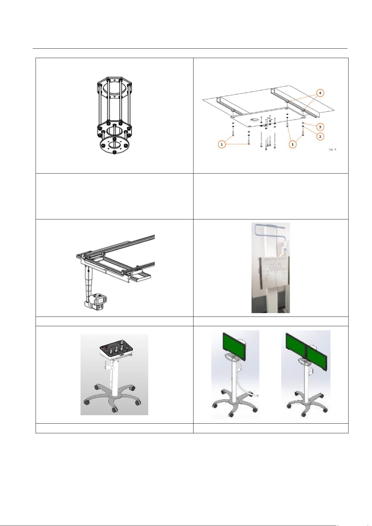
5.1. Ceiling rails (for OTS and / or Monitor suspension) - option
The stationary rails utilize extruded aluminum channels that are ceiling mounted and are 440cm in
length. The spacing between these stationary rails accommodates an overhead mounted bridge
structure. The bridge length is 301cm (or 361cm) and the bridge width is 61cm. The standard distance
between rails is 165cm.
A proper iron beam has been immured in the ceiling in accordance with one of the solutions
suggested in the following figure:
Measures in mm
The calculation of the support structure of the ceiling stand depends exclusively on the designer,
who is responsible of the room preparation. Type and dimension of the T-irons, shown in these
drawings, are just an indication.
Page 34
Discovery RF180
Pre-Installation Manual
GE Healthcare
5793724-1EN, Rev. 6
Page 34
Measures in mm
Code
Description
Quantity
11
CAGE FOR SCREW TE 10
14
12
UNISTRUCT BRACKET H=45
14
N11
SCREW TE 8.8 Z UNI 5739 M10x30
14
N12
PLAIN WASHER D10.5 D30 THICKNESS 3
14
N13
NUT M10 UNI7473 DIN9820
14
N14
SCREW TCEI M10x30 8.8Z UNI5931
28
N15
GROWER WASHER C72Z UNI1751 D10.5
28
N16
PLAIN WASHER B.R40Z D.10.5 UNI6592
28
WARNING:
THE SUSPENSION CEILING RAILS ARE MOUNTED ON THE IRON BEAM BY
MEANS OF A SET OF SCREWS DELIVERED WITH THE UNIT.
EACH FIXATION SCREW MUST RESIST A PULL OF 205 Kg AND IT IS UNDER THE
INSTALLER’S RESPONSIBILITY TO MAKE SURE THAT THE FIXATION METHOD
USED FOR THE IRON BEAM CAN WITHSTAND SUCH VALUE.
WARNING:
IT IS POSSIBLE THAT THE IRON BEAMS IMMURED IN THE CEILING ARE NOT
LEVELLED. THE INSTALLER MUST CAREFULLY VERIFY THAT AND, IF
NECESSARY, LEVEL THE CEILING RAILS USING PROPER SPACERS.
Page 35

GE Healthcare
5793724-1EN, Rev. 6
Discovery RF180
Pre-Installation Manual
Page 35
5.1.1. Maximum flexion between 2 anchoring points
During the worst working equipment conditions, it is necessary to find out the working stress on each
equipment support. The stress force of each equipment part is split into the following items:
P1 = 1000 N Rails (4 of 14 points anchoring)
P2 = 600 N Bridge (it slides on 4 support bearings)
P3 = 1700 N Carriage (stand with tube, collimator, mechanical and electrical parts)
In order to find out rail flexures, the study must be related to a close rectangular shape that
reproduces the rails core dimensions.
If you work in this way, you will always be able to simplify job calculation and in addition we will
always be in a Safety situation
As a matter of fact, rails are more complex, ribs and cores (that in this study are not taken into
consideration) really add large stiffness to the rails
At the same way for the below calculation, the rail steel plate is not taken into consideration that it is
the guide for sliding bearings and as a matter of fact it does add stiffness to the rails too.
If you make reference to the attached drawing you can calculate rails flexure by taking into
consideration the main involved sizes.
P = 2000 N half suspension weight and transversal carriage weight
L = 700 mm distance between rail anchoring points
E = 60000 MPa aluminum modulus of elasticity
I = 365000 mm4 inertia module related to the rail section (make reference to the following
drawings).
As a result, the flexibility of beam rested between extreme sides is calculated by the beam deflection
formula.
Page 36

Discovery RF180
Pre-Installation Manual
GE Healthcare
5793724-1EN, Rev. 6
Page 36
5.1.2. Rail mounting
Make reference to the 5780106-1EN Kalos Service manual par. 6.3.3 “Installation of the Ceiling Rails”.
Page 37

GE Healthcare
5793724-1EN, Rev. 6
Discovery RF180
Pre-Installation Manual
Page 37
5.2. Overhead Tube Suspension
5.2.1. Packaging
ITEM
LENGTH
WIDTH
HEIGHT
WEIGHT
Single packaging in wooden case
(All inclusive)
455.4 cm
90.4 cm
166 cm
920 kg
ITEM
LENGTH
WIDTH
HEIGHT
WEIGHT
Overhead Tube Suspension
longitudinal rails (two packages)
442 cm
12 cm
12 cm
42 kg + 42 kg
Overhead Tube Suspension,
transversal bridge
301 cm
80 cm
140 cm
378 kg
Collimator
58 cm
36 cm
38 cm
25 kg
High voltage cables
65 cm
74 cm
32 cm
15 kg
H = High voltage cables; C = Collimator; R = Longitudinal Rails
Magnetic band
position: do not
cut on this side.
Page 38

Discovery RF180
Pre-Installation Manual
GE Healthcare
5793724-1EN, Rev. 6
Page 38
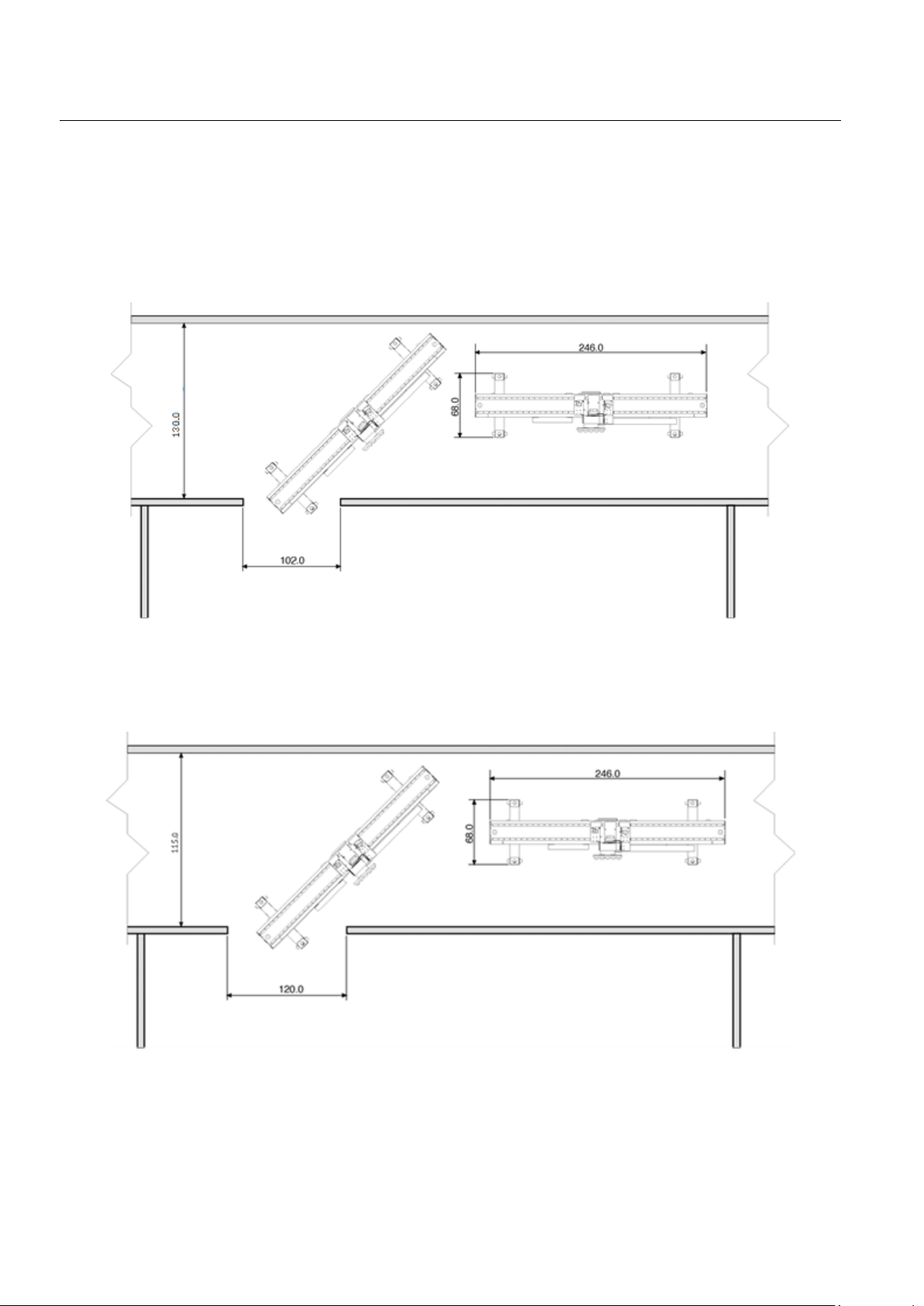
5.2.2. Dimensions
ITEM
LENGTH
WIDTH
Rails area
441 cm
360 cm
The measures in this picture are in millimeters.
Page 39

GE Healthcare
5793724-1EN, Rev. 6
Discovery RF180
Pre-Installation Manual
Page 39
The measures in this picture are in millimeters.
Page 40

Discovery RF180
Pre-Installation Manual
GE Healthcare
5793724-1EN, Rev. 6
Page 40
The measures in this picture are in millimeters.
Page 41

GE Healthcare
5793724-1EN, Rev. 6
Discovery RF180
Pre-Installation Manual
Page 41
5.3. Monitor suspension (single / double) - option
5.3.1. Packaging
ITEM
LENGTH
WIDTH
HEIGHT
WEIGHT
Mounting Plate (option)
79 cm
48 cm
10 cm
25 kg
Substructure for Ceiling Suspension
104 cm
49 cm
33 cm
43 kg
ITEM
LENGTH
WIDTH
HEIGHT
WEIGHT
Rails (only if OTS is not supplied)
450 cm
12 cm
22 cm
12 cm
31 kg +
41 kg
Longitudinal rails and lifting tool are present only if OTS is not supplied
ITEM
LENGTH
WIDTH
HEIGHT
WEIGHT
Monitor Suspension.
Transversal bridge included
455 cm
80 cm
75 cm
382 kg
Page 42

Discovery RF180
Pre-Installation Manual
GE Healthcare
5793724-1EN, Rev. 6
Page 42
5.3.2. Dimensions
The provided device is equipped with only one arm. The following drawings show two arms in order
to have a complete mechanical documentation.
The ceiling suspension spring arm can be moved up and down by max 45°, but this range can be
adjusted/limited; for details, please refer to the monitor manufacturer’s manual. The downward
movement is limited by a lower stop. For upward movement, check clearance with ceiling and avoid
any collision. The extension arm has no up/down movement, but rotates on the column pins. Avoid
alignment of the extension arm and spring arm.
GD4210-L max load 9.5 kg GD4220-L max load 15.0 kg
* dimension for L version. Measures in mm.
Page 43

GE Healthcare
5793724-1EN, Rev. 6
Discovery RF180
Pre-Installation Manual
Page 43
Measures in mm.
Measures in mm.
WARNING
The motion should always be smooth and easy, if any hard point is felt by
moving the system, please contact the manufacturer. If you encounter
damages such as bent ceiling columns, collision marks or cracks in the color
coating or the material of the system, broken plastic covers, loose connection
of parts, or similar, please contact the manufacturer without further delay.
Page 44

Discovery RF180
Pre-Installation Manual
GE Healthcare
5793724-1EN, Rev. 6
Page 44
OVERALL DIMENSION MONITOR
SUSPENSION ON RAILS 1/3 [mm]
OVERALL DIMENSION MONITOR
SUSPENSION ON RAILS 2/3 [mm]
MAXIMUM SUGGESTED DISTANCE FROM FLOOR 3100mm
Page 45

GE Healthcare
5793724-1EN, Rev. 6
Discovery RF180
Pre-Installation Manual
Page 45
OVERALL DIMENSION MONITOR
SUSPENSION ON RAILS 3/3 [mm]
Page 46

Discovery RF180
Pre-Installation Manual
GE Healthcare
5793724-1EN, Rev. 6
Page 46
Table
5.3.3. Packaging – table delivered in one piece
ITEM
LENGTH
WIDTH
HEIGHT
WEIGHT
Table
267 cm
130 cm
232 cm
1500 kg
SFD
120 cm
130 cm
165 cm
220 kg
Table SFD and accessories
Page 47

GE Healthcare
5793724-1EN, Rev. 6
Discovery RF180
Pre-Installation Manual
Page 47
5.3.4. Packaging – table delivered in two pieces
ITEM
LENGTH
WIDTH
HEIGHT
WEIGHT
Main frame + tabletop
260 cm
130 cm
218 cm
1000 kg
Beam, SFD and
accessories
260 cm
130 cm
218 cm
773 kg
Main frame + tabletop
Beam, SFD and accessories
Page 48

Discovery RF180
Pre-Installation Manual
GE Healthcare
5793724-1EN, Rev. 6
Page 48
5.3.5. Dimensions
Measures in [mm].
(*) NOTE: The recommended service area behind the table is 500mm. The minimum service area
behind the table must be 336 mm.
530 mm space left and right the table, represents the anti-collision escape area for operators and
patients.
500 (*) 336 (*)
Rear side
Front side
Page 49

GE Healthcare
5793724-1EN, Rev. 6
Discovery RF180
Pre-Installation Manual
Page 49
To prevent collisions with accidental objects it is a good practice to maintain a clear-area around the
unit as suggested in the following figure. Refer to the dashed line around the table.
Measures in [mm].
Page 50

Discovery RF180
Pre-Installation Manual
GE Healthcare
5793724-1EN, Rev. 6
Page 50
Rear side Front side
Measures in [mm].
Max patient weight on the platform with
vertical machine 266 kg
Page 51

GE Healthcare
5793724-1EN, Rev. 6
Discovery RF180
Pre-Installation Manual
Page 51
Measures in [mm].
Page 52

Discovery RF180
Pre-Installation Manual
GE Healthcare
5793724-1EN, Rev. 6
Page 52
Measures in [mm].
Page 53

GE Healthcare
5793724-1EN, Rev. 6
Discovery RF180
Pre-Installation Manual
Page 53
5.4. Base plate installation
The responsibility for the base plate fixation belongs to the installer and to the pre-installation
team.
The installer must verify the room physical characteristics, in accordance with the information
provided by the pre-installation team in the pre-installation phase.
The method used to fix the base plate must follow the indications provided by the pre-installation
team. It’s on the installer charge to inform that the information received from the pre-installation
team is not suitable for the base plate fixing.
The remote tilting table can be fixed to the floor using one of the following two different methods:
fixation using the underfloor installation plate and fixation using the over floor installation plate.
Before starting the installation, the pre-installation team must verify that all accessories
or interface cables are available and delivered in the lengths defined during the room
layout design phase.
Page 54

Discovery RF180
Pre-Installation Manual
GE Healthcare
5793724-1EN, Rev. 6
Page 54
It is the responsibility of the pre-installation to select the fixation method that grants the
correct unit anchoring in function of the constructive characteristics of the floor. The
team must provide this information regarding the fixation method and the room
physical characteristics to the installer.
WARNING FOR THE OVERFLOOR BASE PLATE
In case of over floor base plate, pay attention to the position of the base plate with the
right orientation. The hole has to be oriented as in the figure, with respect to the main
frame. Otherwise mismatches will occur between the two objects.
Check how the machine will be oriented during installation.
Page 55

GE Healthcare
5793724-1EN, Rev. 6
Discovery RF180
Pre-Installation Manual
Page 55
5.4.1. Use of the under floor installation plate
With this base, the floor loading capability must be greater than 550 kg/m² (unit weight = 1025+80
Kg; patient weight= 323 Kg; loading area = 2,60 m²). In order to correctly install the base plate, the
installer will be responsible to:
• Remove the upper part of the floor for a minimum area of 2200 x 1700mm (x about
100mm):
• Make sure that the floor surface on the bottom side of the base plate is rugged enough to
grant a proper grip of the concrete (it is possible to use a welded mesh.)
• Make sure that the base plate is accurately leveled with the upper plate aligned with the
finished surface of the floor as detailed in the following drawing.
• If required, fix the base plate to the floor using M12 screws as detailed in the following
drawing.
• Insert M12 screws in the unit fixation holes to prevent the possibility that the concrete could
obstruct the eight-unit fixation holes.
• Pour the concrete between cement and sand in a 1:2.5 ratio.
Unit weight = 1025 kg
Patient weight = 323 kg
Plate weight = 80 kg
Loading area = 2.60 m2
Floor loading = 550 Kg/m2
Measures in mm.
The M12 screws are not supplied with the product. Use the same described in the figure or similar.
It is in charge of the structural engineer of the hospital to evaluate whether the floor characteristics
are suitable for this type of base plate.
Cable IN
duct
Rear
Front
Page 56

Discovery RF180
Pre-Installation Manual
GE Healthcare
5793724-1EN, Rev. 6
Page 56
5.4.2. Use of the over floor installation plate
BEFORE INSTALL THE BASEPLATE ON THE FLOOR CHOOSE THE FIXAITION METHOD (three different
here below) IN ACCORDANCE WITH THE FLOOR THICKNESS AN WITH YOUR NEEDS.
This should be done during the PRE-INSTALLATION PHASE.
This fixation method is recommended when the floor characteristics are not suitable to allow the
installation of the under-floor plate (It is in charge of the structural engineer of the hospital to
evaluate whether the floor characteristics are suitable for the under floor base plate.). In this case,
the installer must use the optional over floor installation plate to distribute the weight on a larger
surface and to offer a better and easier fixation to the floor as detailed in the following figure.
It is responsibility of the installer to grant the correct anchoring of the base plate in
function of the constructive characteristics of the floor.
Unit weight = 1025 kg
Patient weight = 323 kg
Plate weight = 180 kg
Loading area = 1.90 m2
Floor loading = 805 kg/m2
Drilling hole depth = 130 mm
(5,1 inches)
Drilling hole diameter = 15 mm
(37/64 inches)
1 → N°1 anchor screw Bossong
2 → N°1 countersunk washer
3 → over-floor plate
Measures in mm
(*) Cable in point: cut the table cover at the predefined weakening point, in correspondence of the
plate hole.
(*)
Front
Rear
Page 57

GE Healthcare
5793724-1EN, Rev. 6
Discovery RF180
Pre-Installation Manual
Page 57
WARNING
Be sure to have completely tightened the screws (torque value in the table below).
Reference to the critical
component on
Installation Manual
Description
Dimension
Number of
elements
According to and
material grade
Torque to apply
[Nm]
Loctite use
Nut size and washers
Embedment depth
[mm]
Material of the parent
to whitch the screw is
mounted on
Component
No
1 and 4
Anchor screw
for fixation of
the over floor
base plate
M10
8
Screw
8.8
55
No
Countersunk
Washer
115.5
Concrete
C20/25
not
cracked
The M10 screws and the washers are supplied with the system.
Remind to tight the screws/bolts using the cross rule.
Default fastening method
Page 58

Discovery RF180
Pre-Installation Manual
GE Healthcare
5793724-1EN, Rev. 6
Page 58
Example of fastening on a 140 mm floor.
Reference to the critical
component on
Installation Manual
Description
Dimension
Number of elements
According to and
material grade
Torque to apply [Nm]
Loctite use
Nut size and washers
Embedment depth
[mm]
Material of the parent
to whitch the screw is
mounted on
Component
No
1 and 4
Anchor screw
for fixation of
the over floor
base plate
M10
8
Screw
8.8
55
No
Countersunk
Washer
90.5
Concrete
C20/25
not
cracked
The M10 screws and the washers are supplied with the system.
Remind to tight the screws/bolts using the cross rule.
The applicability verification of this example is under the responsibility of the room PMI Project
Manager Installation.
Page 59

GE Healthcare
5793724-1EN, Rev. 6
Discovery RF180
Pre-Installation Manual
Page 59
Example of chemical fastening on a 100 mm floor.
(Example of approved chemical is Bossong BCR-300 V-Plus.)
Reference to the critical
component on
Installation Manual
Description
Dimension
Number of elements
According to and
material grade
Torque to apply [Nm]
Loctite use
Nut size and washers
Embedment de
pth
[mm]
Material of the parent
to whitch the screw is
mounted on
Component
No
1 and 4
Anchor screw
for fixation of
the over floor
base plate
M10
8
Screw
8.8
20
No
Nut M10 +
Washer
70
Concrete
C20/25
not
cracked
ANCHORAGE DIAGRAM MINIMUM THICKNESS 100 MILLIMETER MINIMUM
Screws type M10 (screws, nuts and the washers included in the shipment).
Remind to tight the screws/bolts using the cross rule.
Measure in millimeters.
NOTE: the hole must be perfectly clean.
The applicability verification of this example is under the responsibility of the room PMI Project
Manager Installation.
Not all fastening options are obtainable if customer site is in seismic / OSHPD regions. It is required
to work with regional guidelines for expectable floor thickness that is greater than the options
below to meet code.
WARNING
Install according the
screw manufacturer’s
instruction.
Page 60

Discovery RF180
Pre-Installation Manual
GE Healthcare
5793724-1EN, Rev. 6
Page 60
5.5. Table main control console
5.5.1. Packaging
The main control console is not shipped with a separate package. It is included in the Package 2,
referring to the Unpacking Procedure in the Installation Manual.
5.5.2. Dimensions
Measures in mm.
Page 61

GE Healthcare
5793724-1EN, Rev. 6
Discovery RF180
Pre-Installation Manual
Page 61
5.6. In-room secondary console (option)
5.6.1. Packaging
ITEM
LENGTH
WIDTH
HEIGHT
WEIGHT
In-room secondary console
shipping pack
130 cm
(51.2in)
47 cm
(18.5in)
50 cm
(19.7in)
50 kg
(110 lbs)
5.6.2. Dimensions
The measures are in millimeters.
Page 62

Discovery RF180
Pre-Installation Manual
GE Healthcare
5793724-1EN, Rev. 6
Page 62
5.7. Generator Cabinet
5.7.1. Packaging
The dimensions of the packed Indico IQ® X-ray generator are shown in the table below.
ITEM
LENGTH
WIDTH
HEIGHT
WEIGHT
Main cabinet in shipping pack
71 cm (28in)
61 cm (24in)
132 cm (52in)
* 109-118 kg
(240-260 lbs)
* The packed weight of the generator will vary within the specified range depending on console type
and options.
5.7.2. Dimensions
ITEM
LENGTH
WIDTH
HEIGHT
WEIGHT
Generator cabinet (wheels are
optional / not included)
50.8 cm
(20 in)
41 cm (16 in)
106cm
(41.5in)
91 kg
(200 lbs)
Measure in inches (mm)
A minimum of 3 inches (76 mm) of clearance is required between the back of the generator and any
wall behind the generator. Areas around the generator vents must be unobstructed to prevent
overheating.
Cable conduits, troughs or raceways should be provided to route cables from the generator cabinet
to the console and to the room equipment if required. These should be large enough to allow the
cables to be routed without risk of damage.
Sufficient room must be provided to allow access to the generator for installation. A minimum of 42
inches (1.07 m) clearance is recommended on any side for which service access may be required
during installation. This is to minimize the risk of accidentally contacting high voltage during service
and maintenance.
Page 63

GE Healthcare
5793724-1EN, Rev. 6
Discovery RF180
Pre-Installation Manual
Page 63
5.8. Digital system
5.8.1. Packaging
The digital system is shipped with the detector/detectors in a single package.
ITEM
LENGTH
WIDTH
HEIGHT
WEIGHT
Main cabinet in shipping pack
73 cm
65 cm
154 cm
160 kg
A minimum of 10 cm of clearance is required around the digital system. Areas around the digital
system grids must be unobstructed to prevent overheating.
In order to aid installation and maintenance activities, the system stands on wheels. This allows
shorts repositioning for accessing the internal component.
A minimum of 100 cm clearance is recommended on front and rear sides during installation and
maintenance.
Cable routing should be large enough to allow the cables to be routed without risk of damage.
Tray locking
system during
transportation.
Wiring
access.
Page 64

Discovery RF180
Pre-Installation Manual
GE Healthcare
5793724-1EN, Rev. 6
Page 64
5.8.2. Dimensions
ITEM
LENGTH
WIDTH
HEIGHT
WEIGHT
Digital Cabinet
66 – 74 cm
57 cm
90 cm
110 kg
Lateral view
Top view
Measures in mm
Page 65

GE Healthcare
5793724-1EN, Rev. 6
Discovery RF180
Pre-Installation Manual
Page 65
5.9. Monitor
5.9.1. Packaging
ITEM
LENGTH
WIDTH
HEIGHT
WEIGHT
Monitor 23”
18.5 cm
62.5 cm
46.5 cm
8.6 kg
5.9.2. Dimensions
ITEM
LENGTH
WIDTH
HEIGHT
WEIGHT
Monitor 23”
22 / 40 cm
56 cm
36 cm
6.6 kg
Measures in mm.
Page 66

Discovery RF180
Pre-Installation Manual
GE Healthcare
5793724-1EN, Rev. 6
Page 66
5.10. Monitor Advantech
5.10.1. Packaging
ITEM
LENGTH
WIDTH
HEIGHT
WEIGHT
Monitor 24”
71.5 cm
18.5 cm
59.5 cm
11 kg
Weight includes external power supply (1 kg).
5.10.2. Dimensions
ITEM
LENGTH
WIDTH
HEIGHT
WEIGHT
Monitor 24”
68 cm
57.8 cm
40.3 cm
7.8 kg
Measures in mm.
ITEM
LENGTH
WIDTH
HEIGHT
WEIGHT
Display stand
222 mm
252 mm
432 mm
3.2 kg
For desk installation.
Page 67

GE Healthcare
5793724-1EN, Rev. 6
Discovery RF180
Pre-Installation Manual
Page 67
5.11. Monitor cart
5.11.1. Packaging
ITEM
LENGTH
WIDTH
HEIGHT
WEIGHT
Monitor cart (without monitor)
47 cm
47 cm
140 cm
10 kg
5.11.2. Dimensions
Page 68

Discovery RF180
Pre-Installation Manual
GE Healthcare
5793724-1EN, Rev. 6
Page 68
Single monitor cart
ITEM
LENGTH
WIDTH
HEIGHT
WEIGHT
Monitor cart (with monitor)
898 mm-
811 mm
1497 mm
--- kg
Measures in mm.
Page 69

GE Healthcare
5793724-1EN, Rev. 6
Discovery RF180
Pre-Installation Manual
Page 69
Double monitor cart
ITEM
LENGTH
WIDTH
HEIGHT
WEIGHT
Monitor cart (with monitors)
1137 mm-
811 mm
1497 mm
--- kg
Measures in mm.
Page 70

Discovery RF180
Pre-Installation Manual
GE Healthcare
5793724-1EN, Rev. 6
Page 70
5.12. Wall Stand - option
5.12.1. Packaging
ITEM
LENGTH
WIDTH
HEIGHT
WEIGHT
Wall Stand (not tilting)
248 cm
73 cm
83 cm
222 kg
Wall Stand (tilting)
(not available for US)
248 cm
73 cm
83 cm
251 kg
Measures in mm.
The case content is:
The stand (fastened lying down in a horizontal position), complete with bucky carriage (and detection
chamber according to the customer’s requests);
The box contains the small blocks for fixing the wall stand some additional screws, and the optional
accessories to complete the equipment installation and its manuals.
Page 71

GE Healthcare
5793724-1EN, Rev. 6
Discovery RF180
Pre-Installation Manual
Page 71
5.12.2. Dimensions
ITEM
LENGTH
WIDTH
HEIGHT
WEIGHT
Wall Stand Not tilting
40 cm
(46 cm)
62 cm
239 cm
(277 cm*)
171 kg
* with arm holder accessory
Total weight 171 kg
Center of
gravity
A: not used
B: floor base fastening or
floor and wall fastening
Measure [mm]
Page 72

Discovery RF180
Pre-Installation Manual
GE Healthcare
5793724-1EN, Rev. 6
Page 72
ITEM
LENGTH
WIDTH
HEIGHT
WEIGHT
Wall Stand Tilting
(not available for US)
66 cm
(72 cm)
62 cm
239 cm
(263 cm)*
200 kg
* with arm holder accessory
Total weight 200 kg
Center of
gravity
A: not used
B: floor base fastening or
floor and wall fastening
Measure [mm]
Page 73

GE Healthcare
5793724-1EN, Rev. 6
Discovery RF180
Pre-Installation Manual
Page 73
5.12.3. Wall Stand Base Plate and Wall Bracket
Wall stand fixation onto the floor and onto the floor and wall. Measures in mm.
Wall bracket (for wall fixation). Measure in [mm]
Page 74

Discovery RF180
Pre-Installation Manual
GE Healthcare
5793724-1EN, Rev. 6
Page 74
5.13. Wall stand and Table Layout
The recommended distance of the base plate rear from the wall is 500 mm. The minimum
distance of the base plate rear from the wall must be 336mm.
During the installation, the recommended distance from the wall for the generator is 1,07 m (42
inches). During normal use, a minimum distance of 76 mm (3 inches) is required.
The minimum distance from the wall for the digital system is 100 mm (4 inches).
Lower distances could prevent proper maintenance.
Safety distances from the wall must be respected. For the positioning of the devices inside the
room, it is necessary to consider cables length.
LEGEND
1) Table
2) Generator power cabinet
3) Operative limit
4) Control desk
5) Main console
6) Room power electrical board
7) Anti-X glass
8) Monitor on cart
9) Monitor+keyboard+mouse
10) Digital system cabinet
11) UPS
12) Bucky stand
NOTE: The recommended service
area behind the table is 500mm.
The minimum service area behind
the table must be 336 mm.
Example of positioner table with wall stand. Measures in mm.
(*) This layout is an example. Specific details regarding room dimensions and system-wall distances
will be considered with the pre-installation team.
*
336
*
Page 75

GE Healthcare
5793724-1EN, Rev. 6
Discovery RF180
Pre-Installation Manual
Page 75
5.14. Detector
The detector must be stored and handled within its original larger outer cardboard box. Do not open
this outer box if there is no need.
While not used nor powered, the detector should be stored within the inner protective bag resealed
or reclosed with an adhesive tape, and using desiccant material inside the bag to avoid any humidity
on the detector.
5.14.1. Packaging
The detectors are shipped with the digital system in a single package.
ITEM
LENGTH
WIDTH
HEIGHT
WEIGHT
Detector Pixium 4343FL
70 cm
64 cm
31 cm
21 kg
Detector Pixium 4343RF
72 cm
72 cm
31 cm
32 kg
Wifi Detector Pixium 3543EZ
63 cm
67 cm
25 cm
10 kg
Wifi Detector Pixium 2430EZ
63 cm
67 cm
25 cm
10 kg
PU**
N.A.
N.A.
N.A.
N.A.
** The PU unit is already installed into the digital system cabinet. Make reference to the Digital
System information
The cardboard box and the inner protective bag have to be opened with care in order to be reused.
Unpacking procedure:
a) Open the cardboard box using the two fasteners on the front side of the box.
b) Remove the inner protective bag from the box (See next page for continuation of
instructions).
CAUTION!
Do not open the inner protective bag before a sufficient acclimatization time. The acclimatization
time is specified as 7h30 hours (minimum). It is mandatory to remove the detector from the
cardboard box during this time – however do not under any condition open the sealed protective
bag during this time. Refer to the PIXIUM FE 4343 [R or F] specification for storage conditions
(environmental temperature and humidity, etc...) of the detector once the protective bag has been
opened at the end of this acclimatization time.
c) In order to open the inner protective bag, cut off only the sealed part of the bag.
d) Immediately after opening the inner protective bag, check and note the value provided by
humidity indicator placed inside the bag.
e) A digital readout thermometer is placed inside the inner cardboard box, to record max and
min temperatures during transport and storage. To read these temperatures, just press
MAX/MIN pushbutton and note the indications. Refer to the PIXIUM FE 4343 [R or F]
specification for specified temperature values.
f) Keep the following original parts in a secure place in case of detector return :
Page 76

Discovery RF180
Pre-Installation Manual
GE Healthcare
5793724-1EN, Rev. 6
Page 76
• cardboard box,
• foams,
• digital thermometer,
as well as a new inner protective bag (with Velcro strip) which contains a small sealed bag
with desiccant material bag and a new humidity indicator. DO NOT OPEN this small sealed
bag as it will be used in the case of any detector return. Take care to not apply undo shocks
to the shipping containers even if empty.
5.14.2. Dimensions
ITEM
LENGTH
WIDTH
HEIGHT
WEIGHT
Detector Pixium 4343FL
49 cm
50 cm
4,6 cm
14 kg
Detector Pixium 4343RF
51 cm
52 cm
4,6 cm
25 kg
Wifi Detector Pixium 3543EZ
38 cm
46 cm
1,5 cm
3 kg
Wifi Detector Pixium 2430EZ
26,5 cm
32,5 cm
1,5 cm
2 kg
Detector Pixium 4343FL. Measures in mm.
Page 77

GE Healthcare
5793724-1EN, Rev. 6
Discovery RF180
Pre-Installation Manual
Page 77
5.15. Access Point
5.15.1. Packaging
The access point is not shipped with a separate package. It is included in the Package 2.
5.15.2. Dimensions
ITEM
LENGTH
WIDTH
HEIGHT
WEIGHT
Access Point
170 mm
170 mm
28 mm
316 g
Place this component inside the room.
Page 78

Discovery RF180
Pre-Installation Manual
GE Healthcare
5793724-1EN, Rev. 6
Page 78
6. Planning Electrical Connections
6.1. Routing Cables
The dimension of cable ducts should be 20x8 cm or larger.
Smaller ducts may lead to difficulties during installation.
6.1.1. General
Whenever possible, keep high-voltage and power cables away from any other cables. Use separate
trough in duct system. Minimize cable length between the line disconnect and the system cabinet
power unit to reduce voltage regulation problems and wiring costs. For information about the cables
supplied with your system, please refer to the paragraph “Schematic overview and cable list” in the
System Installation manual.
6.1.2. Conduit
Using conduit imposes some important considerations when used with this system. Of primary
concern, the majority of cables used are pre-terminated. Pre-termination greatly simplifies
interconnection but makes cable-pulling difficult because of the added dimensions of the connectors.
Conduit must be large enough to pass the cable and connector through with all other cables already
in the conduit. Also, the size of conduit chosen must allow for future growth. There’s the possibility of
additional cables being added later as the system is developed and options are added. The use of
conduit is recommended for cables running overhead between rooms, especially when a diagonal
run provides the shortest cable path.
6.1.3. Floor Ducts
Floor ducts have advantages when used with a single room or two adjacent rooms. Floor duct
combines cabling in a neat, functional appearance with accessibility and room for expansion. The
disadvantage is the amount of work required to install it, which is generally prohibitive in existing
installations. For the same reason, it is impractical to attempt to add on to existing floor duct
systems.
6.1.4. Power Distribution
Make reference to the par. 8.2 Electrical Requirements page 89.
6.1.5. Emergency Power
R&F rooms may be used as critical care areas. Primary power to the patient table auxiliary outlets
should be distributed from the customer's emergency power branch. The auxiliary outlets may have
life-support devices plugged in that must remain on during a power failure in the main branch. This
will require a separate, independent circuit breaker so service personnel can remove all power from
the table during installation and servicing without removing power from the room outlets. Always
check local codes for emergency power requirements.
Page 79

GE Healthcare
5793724-1EN, Rev. 6
Discovery RF180
Pre-Installation Manual
Page 79
6.2. Master Interconnect System (MIS)
System interconnect cables are described in MIS (Master Interconnect System) documents shipped
with the system. These documents specify all interconnections between components within the
system and its options.
Note: for specific system interconnect maps and connection details please refer to the System Service
Manual.
6.3. Hospital Network Connections
All Digital systems are equipped with Broadband fast Ethernet hardware for Service Diagnostics. The
systems equipped with Digital Imaging are capable of placing electronic images on the Hospital image
Ethernet Network (DICOM).
The Digital PC (part of the Digital subsystem) is the connectivity point between the system and the
hospital. For a Broadband connection, it is the purchaser’s responsibility to provide the connection at
the Ethernet port on the Digital PC via a Cat 5 Ethernet cable and the hospital Ethernet connection.
Note: System hardware is rated at 100/1000Mbs transfer rate. Hospital connections must be rated
for 100/1000Mbs for optimal performance. One RJ45 Ethernet plug should be present in the room.
6.3.1. Remote services broadband pre-installation requirements for Europe
To enable an easier installation and to benefit from remote support (service and engineering teams),
the equipment should be connected to installation on site.
Thus, the connectivity solution to implement should be decided during pre-installation and all related
data should be available before installation starts.
For all installations make sure that you have at least one RJ45 dedicated to connect the new
equipment on the LAN.
In case of Broadband, this connection will also be used for the remote service of the equipment.
The distributor offers a wide range of connectivity solutions.
Network devices (like CISCO Routers for instance) can be shipped with the equipment only if the
Sales Representative has added the connectivity item in the order.
For complete descriptions of these connectivity solutions, please refer to the Broadband Solutions
catalogue.
Connectivity Process and pre-installations checklists are available in the Broadband Connectivity PIM.
For each solution selected by the customer the pre-installation checklist must be fulfilled by site IT
manager in order to get connectivity information (site IT manager contacts, IP address…) available at
installation.
6.3.2. RSVP Network requirements
System should be connected to external network in order to reach RSVP server. Port 443 has to be
opened. Check with your Connectivity leaders if hospital network is ready for RSVP.
Page 80

Discovery RF180
Pre-Installation Manual
GE Healthcare
5793724-1EN, Rev. 6
Page 80
6.3.3. DICOM hospital Network
If the customer wants to use the DICOM services provided by the digital system, please be sure to
have a Local Area Network plug (RJ45 type) connected to the Hospital Network and one Ethernet
cable cat. 5 for the connection to the digital system DICOM network board (connector B11C4).
The customer must also supply the following information:
• Local Network board TCP-IP address (or the indication to use the DHCP service);
• Local Digital PC “Station Name” (Local AE title);
• DICOM Store Server AE title;
• DICOM Store Server TCP-IP address and port number;
• DICOM Print Server AE title;
• DICOM Print Server TCP-IP address and port number;
• DICOM Worklist Server AE title;
• DICOM Worklist Server TCP-IP address and port number;
• DICOM MPPS Server AE title;
• DICOM MPPS Server TCP-IP address and port number;
• DICOM Dose SR Store Server AE title (option);
• DICOM Dose SR Store Server TCP-IP address and port number (option);
Option
Only in case the customer wants to grant Internet access to this device, also the following
information is needed:
• Default gateway TCP-IP address;
• Preferred DNS server (or the indication to use the DHCP service)
• Alternate DNS server (option)
ATTENTION
The customer MUST be aware of the risks concerning cybersecurity of an enabled Internet
connection.
Internet connection can be activated only if the user logs in Windows as “Administrator”. The
normal Windows user “Operator” can never connect to Internet.
Page 81

GE Healthcare
5793724-1EN, Rev. 6
Discovery RF180
Pre-Installation Manual
Page 81
7. Laying Out the Room
7.1. Considerations
7.1.1. Privacy and security
It is strongly recommended that the system is installed in a secure location and is protected from
physical access by unauthorized individuals. It is recommended that the room where the system is
installed is access controlled and audited by either physical or electronic means.
The monitors should be placed in a way limiting the visibility to the user only.
The computer should be physically secured in a way that it is not physically accessible to unintended
use.
The digital system should be connected to a secured network, not open to unintended users or hosts.
7.1.2. Radiation Protection
Because X-ray equipment produces radiation, you may need to take special precautions or make
special site modifications. GE Medical Systems does not make recommendations regarding radiation
protection. It is the purchaser’s responsibility to consult a radiation physicist for advisement on
radiation protection in X-ray rooms.
Remember to locate the User Interface per local codes and regulations. The IUI must not be located
anywhere there’s a possibility of exposing the operator to radiation during use. This includes
operation of the system using the hand switch. The hand switch is on the right side of the unit, and
cannot be relocated to the left side.
7.1.3. Service Access
Allow appropriate space for service access of equipment. Consult component pre-installation
directions for clearance information.
7.1.4. Clinical Access
Make sure that you plan the room with the following clinical access requirements:
• Provide easy access to the patient table. Stretchers and other mobile hospital equipment
must reach the table quickly.
• Clinicians at the patient table must be able to communicate with assistants in the control
area monitoring equipment from the table.
• Operators in the control area must have easy access to the control console. However,
position the controls (including hand switches) so the operator cannot take exposures while
looking around or standing outside the control booth's lead glass window.
• Operators in the control area must have easy access to video recorders and injector
programmers, film and video storage cabinets, and service and operating manuals.
• Consult customer on the number and location of non-electrical lines (air, oxygen, vacuum,
water, etc.) in the room.
Page 82

Discovery RF180
Pre-Installation Manual
GE Healthcare
5793724-1EN, Rev. 6
Page 82
7.1.5. Peripheral Equipment
Consult hospital personnel regarding additional space requirements for the following types of
hospital equipment:
• storage cabinets
• sinks
• oxygen stations
• IV apparatus
Page 83

GE Healthcare
5793724-1EN, Rev. 6
Discovery RF180
Pre-Installation Manual
Page 83
7.2. Typical Room Layout
The remote tilting table can be installed in a room that has been officially approved for the operation
of radiological equipment of the same class.
In addition, proper operation of the unit can be achieved only if the environmental characteristics
specified in the following sections are strictly observed.
The recommended distance of the base plate rear from the wall is 500 mm. The minimum
distance of the base plate rear from the wall must be 336mm.
During the installation, the recommended distance from the wall for the generator is 1,07 m (42
inches). During normal use, a minimum distance of 76 mm (3 inches) is required.
The minimum distance from the wall for the digital system is 100 mm (4 inches).
Lower distances could prevent proper maintenance.
Safety distances from the wall must be respected. For the positioning of the devices inside the
room, it is necessary to consider cables length.
A typical room layout (without OTS and wall stand) could be the following one.
LEGEND
1) Table
2) Generator power cabinet
3) Operative limit
4) Control desk
5) Main control console
6) Room power electrical board
7) Anti-X glass
8) Monitor on cart
9) Monitor+keyboard+mouse
10) Digital system cabinet
11) UPS
NOTE: The recommended service
area behind the table is 500mm.
The minimum service area
behind the table must be 336
mm.
Measures in mm.
500
500
*
Page 84

Discovery RF180
Pre-Installation Manual
GE Healthcare
5793724-1EN, Rev. 6
Page 84
A typical layout with OTS and wall stand could be the following one.
WARNING:
it is important that the longitudinal OTS rails are parallel to the table longitudinal movement.
LEGEND
1) Table
2) Ceiling suspension
3) Bucky stand
4) Generator power cabinet
5) Operative limit
6) Control desk
7) Main control console
8) Room power electrical board
9) Anti-X glass
10) Monitor on cart
11) Monitor+keyboard+mouse
12) Digital system cabinet
13) UPS
14) Ceiling suspension cable IN (*)
15) Cable out from the generator for
the ceiling suspension
NOTE: The recommended service
area behind the table is 500mm. The
minimum service area behind the
table must be 336 mm.
(*) The ceiling cable IN is on the right or on the left, according to the generator position (right or left).
This information must be provided to the manufacturer in the pre-installation phase.
In this example, the cable exit RIGHT is chosen because the generator is on the right.
The system is shipped already cabled. If you need to change the cable exit, make reference to
procedure in the OTS Service Manual.
300 cm
336
500 recommended
*
Page 85

GE Healthcare
5793724-1EN, Rev. 6
Discovery RF180
Pre-Installation Manual
Page 85
* The max extremity length is = 350 mm. ** 660 mm steps are also possible.
*
**
Page 86

Discovery RF180
Pre-Installation Manual
GE Healthcare
5793724-1EN, Rev. 6
Page 86
For both layouts, the following drawings illustrate how to perform cable conduit and plate fixing.
Measures in mm.
Recommended opening for duct should be 20x10 cm.
In case of ducts fixed in the floor, also the connectors have to be passed through the ducts. So, it is
important to dimension the ducts correctly. The following indications are listed as guideline to
understand the overall space needed to pass connectors and cables:
- metal cylindrical 6 inches (15,3 cm) diameter ducts for power cables,
- metal cylindrical 7 inches (17,8 cm) diameter ducts for signal cables,
- metal cylindrical 3 inches (7,7 cm) diameter ducts for console and first monitor cables.
(*) NOTE: This distance is 700mm (200+500) if the 500mm recommended service area behind the
table is used. It must be 536 (200+336) if the 336mm minimum service area behind the table is used.
5200
5200
3056
700*
Page 87

GE Healthcare
5793724-1EN, Rev. 6
Discovery RF180
Pre-Installation Manual
Page 87
Unit weight = 1025+323 kg measure in mm
Loading area = 2.60 m2
Plate weight = 80 kg
Floor loading >= 550 kg/m2
(*) NOTE: The recommended service area behind the table is 500mm. The minimum service area
behind the table must be 336 mm.
It is important to check the floor composition: other materials different from concrete floors should
be managed by the costumers in order to guarantee a good plate fixation.
336
500*
Page 88

Discovery RF180
Pre-Installation Manual
GE Healthcare
5793724-1EN, Rev. 6
Page 88
Unit weight = 1025+ 323 kg measure in mm
Plate weight = 180 kg
(*) NOTE: The recommended service area behind the table is 500mm. The minimum service area
behind the table must be 336 mm.
5200
5200
1750
Page 89
GE Healthcare
5793724-1EN, Rev. 6
Discovery RF180
Pre-Installation Manual
Page 89
8. System Facility Power and Grounds
8.1. Introduction
All the control electronics of the remote tilting table has the 0V grounded.
It is consequently clear that a grounding error in the installation or a ground connection made with a
cable of inadequate section may degrade both reliability and safety level of the unit.
The following rules must be observed for a correct grounding:
1 Check that the central ground terminal in the examination room has the characteristics
specified in the safety norms of the country. In particular ground resistances lower than 2
is suggested.
2 Connect the central ground terminal directly to the central ground terminal of the power
distribution box by means of a 4 mm² singe conductor if the distance is less than 10 m. The
cable section must be increased proportionally in case of higher distances.
3 Connect all ground internal cables only to the central ground terminal of the unit located in
the upper side of the power cabinet as shown in the following figure. Make sure that the
brass fixation screws have been properly tightened.
4 Do not add other ground connections that might involve sections of the system, in order to
avoid the possibility to cause ground loops.
8.2. Electrical Requirements
8.2.1. Power quality and System Power Specifications
System power and absorbance
Device
Voltage
Momentary
Power
Standby Power
Table
400Vac
4kVA
600VA
Generator 65kW
400Vac
95 kVA
300VA
480Vac
95 kVA
300VA
Generator 80kW
400Vac
115 kVA
300VA
480Vac
115 kVA
300VA
Digital system
230Vac
350VA
300VA
OTS Overhead Tube Suspension
220/230/240 Vac
1370 VA
100VA
NOTE: the presence of two auxiliary 230 Vac plugs could be useful in the radiological room and in the
control room for the connection of service tools as laptop PC or dosimetry devices.
NOTE: FOR US ONLY, S13441MD Mains Disconnect Panel and Transformer may be purchased from GE
for US Installations to provide the above power requirements. (the MDP does not require a neutral
line).
IMPORTANT NOTICE FOR THE INSTALLER:
Page 90

Discovery RF180
Pre-Installation Manual
GE Healthcare
5793724-1EN, Rev. 6
Page 90
The input line of each component must be protected by means of a safety switch, calibrated for a maximum
leakage current of 30 mA.
Page 91

GE Healthcare
5793724-1EN, Rev. 6
Discovery RF180
Pre-Installation Manual
Page 91
Page 92

Discovery RF180
Pre-Installation Manual
GE Healthcare
5793724-1EN, Rev. 6
Page 92
Page 93

GE Healthcare
5793724-1EN, Rev. 6
Discovery RF180
Pre-Installation Manual
Page 93
Page 94

GE Healthcare
5793724-1EN, Rev. 6
Discovery RF180
Pre-Installation Manual
Page 94
Calculation of overvoltage in the electric cabinet according to CEI 17-43
Electric Cabinet: DIGITAL / REMOTE ROOM
Cabinet Type:800X585X300MM
Frame Dimensions: Height : 800 mm
Width : 585 mm
Depth : 300 mm
No. Diaphragms: 0
Material: Thermal transmission K:3,5
Maximum radiant power from the [W] frame:146W Casing constant (k):0517
Calculation of the actual cooling
surface
Cabinet wall
Size [mm x mm]
Wall surface
A0[m2]
Surface
Factor b
Effective Surface
A0 x b [m2]
Upper Compartment
585X300
0,18
1,4
0,25
Front side
585X800
0,47
0,9
0,42
Rear side
585X800
0,47
0,5
0,23
Left side
300x800
0,24
0,9
0,22
Right wall
300x800
0,24
0,9
0,22
Effective total surface
Ae=Σ (A2 x b) = total [ m
2
] 1.33mq
General data
Temperature data
Power data
Environment
Temperature
20
Installed Power [W]
160,30 W
Maximum temperature
inside the Cabinet
50
Usage factor
0,30
Simultaneity factor
0,60
Effective power dissipated in the
Cabinet [W]
28,85 W
Calculation results
Calculation results: Temperatures
Calculation results: Cooling
Average
temperature in the
Cabinet
27,4
Air Inlet Section
2
Opening [cm]
Maximum temperature
in the Cabinet
31.4
Air volume required
3
for the fan [m / h]
Cabinet Delta
Temperature
3,30K
Thermal input Required for
the Heat Exchanger [W / K]
Delta Temperature at
the top of the Cabinet
11,40K
Cooling power required for
the air conditioner [W]
Page 95

GE Healthcare
5793724-1EN, Rev. 6
Discovery RF180
Pre-Installation Manual
Page 95
8.2.2. Table Electrical requirements
The remote tilting table requires the connection to an electrical line with the following
characteristics:
Line Voltage
380 / 400V 3-phases
Line Voltage tolerance
10 % ( absolute max. rating )
Line frequency
50 Hz – 60 Hz
Line frequency tolerance
2 %
Stand-by power
600 VA
Peak power
4.000 VA
The standard configuration of the units includes the 380 / 400V 3-phase insulation transformer. In
case the line voltage is different from the standard one.
If possible, it is also a good norm to apply the following rules for the line connection:
• The input line must be totally independent from any other lines that might create
interference.
• The main line cable is laid in conduit separate from the cable conduit.
• The section of the line cables must be minimum 4.0 mm2.
• In case the input line characteristics do not match the requirements, it is a good practice to
install a line conditioner.
The input line cable must be connected at the power cabinet line terminals, as detailed in the
following figures.
IMPORTANT NOTICE FOR THE INSTALLER:
The input line must be protected by means of a safety switch, calibrated for a
maximum leakage current of 30 mA.
Page 96

Discovery RF180
Pre-Installation Manual
GE Healthcare
5793724-1EN, Rev. 6
Page 96
8.2.3. Generator Electrical Requirements
Note: Shunt trip circuit breaker required.
The main circuit breaker supplied by the customer must be sized in accordance with local regulations
and have remote (shunt) trip.
In particular, the general requirements of the room input line are:
Line Voltage
400V 3-phase
Line Voltage tolerance
10 % ( absolute max. rating )
Line frequency
50 Hz – 60 Hz
Line frequency tolerance
2 %
Line input reactive power (peak)
95kVA or 115 kVA
Line input active power
65kW or 80 kW
Power source impedance @ 400V
0.13 or 0.11
Stand-by current
< 0.5 A
Page 97

GE Healthcare
5793724-1EN, Rev. 6
Discovery RF180
Pre-Installation Manual
Page 97
8.3. UPS Electrical Requirements
This option is not valid for US.
Input Line Voltage
208-240 Vac
Input Line frequency
50 Hz – 60 Hz ( 5 %)
Power
2000VA
Output Voltage
230Vac (default)
Output Voltage tolerance
2 %
Output frequency
50 Hz – 60 Hz ( 3 %)
Digital cabinet UPS OP2003 (rear)
From Power
Distribution
Box
Page 98

Discovery RF180
Pre-Installation Manual
GE Healthcare
5793724-1EN, Rev. 6
Page 98
8.4. Electrical Grounds
If a neutral line is provided with the system, under no circumstances is it to be used for ground
purposes. The ground conductor only may carry fault currents.
Table ground connection
Generator ground connection
Console ground connection (main and secondary)
Page 99

GE Healthcare
5793724-1EN, Rev. 6
Discovery RF180
Pre-Installation Manual
Page 99
Digital system ground connection
Page 100

Discovery RF180
Pre-Installation Manual
GE Healthcare
5793724-1EN, Rev. 6
Page 100
OTS ground connection
Wall stand ground connection
GND
 Loading...