

Humi
Lab
Relativ
e Humidity Generator
Oper
ator’s Manual
500 Research Drive
Wilmington MA 01887-4498
Tel: 800-33HUMID (800-334-8643)
Fax: 978-203-1919 www.generaleastern.com
Safety:
T
his manual as well as safety labels posted on the instrument use the following safety
alerts to draw your attention to special safety instructions that should be followed.
C
CAU
TION:
W
ARNING:
AUTI
Hazards or unsafe practices could result in electrical shock, minor
injury, or product damage.
W
AR
Refer to accompanying document for additional information.
ON
NING
ALERT
A
LERT:
W
indows and Windows XP are trademarks of Microsoft Corp.
The information in this manual is believed to be reliable. However, GE General Eastern makes no warranty, expressed or implied, as to its
accuracy and assumes no liability arising out of its use by others. We reserve the right to change this manual without prior notice.
Document No. A40241708
Revision B.00 ECO #6498
June 2004 Printed in U.S.A
Copyright © 2003, 2004 GE General Eastern
Earth ground connection; removal could result in electrical shock,
minor injury, or product malfunction.
GE General Eastern
500 Research Drive
Wilmington, MA 01887
Tel: 978 203 1900
Fax: 978 203 1919
Email: generaleastern@ge.com
Web: www.generaleastern.com

C
ONTENTS
INTRODUC
CHAPTER 1 — INST
CHAPTER 2 — OPERATION
TION
- - - - - - - - - - - - - - - - - - - - - - - - - - - - - - 1
About GE General Eastern - - - - - - - - - - - - - - - - - - - - - - 1
Overview of the Humilab - - - - - - - - - - - - - - - - - - - - - - - 2
About this Owner’s Manual - - - - - - - - - - - - - - - - - - - - - - 2
ALLATION AND INITIAL SETUP
Introduction - - - - - - - - - - - - - - - - - - - - - - - - - - - - - 4
Pre-Installation - - - - - - - - - - - - - - - - - - - - - - - - - - - - 4
Components shipped with the Humilab - - - - - - - - - - - - - - - 4
System diagram - - - - - - - - - - - - - - - - - - - - - - - - - - - 5
Installation - - - - - - - - - - - - - - - - - - - - - - - - - - - - - - 6
Place the Humilab at its operating site - - - - - - - - - - - - - - 6
Connect a dry gas source (optional) - - - - - - - - - - - - - - - - 6
Electrical connections - - - - - - - - - - - - - - - - - - - - - - - - 8
Rear input/output fitting connections - - - - - - - - - - - - - - - - 9
Initial setup and water fill - - - - - - - - - - - - - - - - - - - - - 11
Chilled mirror setup - - - - - - - - - - - - - - - - - - - - - - - - 12
Initialize the dew point sensor - - - - - - - - - - - - - - - - - 12
Clean and balance the dew point sensor - - - - - - - - - - - - 13
Shipping the Humilab - - - - - - - - - - - - - - - - - - - - - - - 15
- - - - - - - - - - - - - - - - - - - - - - - - 16
Introduction - - - - - - - - - - - - - - - - - - - - - - - - - - - - 16
Front panel displays and switches - - - - - - - - - - - - - - - - - 17
Performing routine calibrations - - - - - - - - - - - - - - - - - - - 20
Chamber response time - - - - - - - - - - - - - - - - - - - - - - 21
- - - - - - - - - - - - 4
CHAPTER 3 — USING THE P
Introduction - - - - - - - - - - - - - - - - - - - - - - - - - - - - 22
Installing the Prostep software - - - - - - - - - - - - - - - - - - - 23
Running Prostep - - - - - - - - - - - - - - - - - - - - - - - - - - 24
CHAPTER 4 — T
Overview - - - - - - - - - - - - - - - - - - - - - - - - - - - - - - 30
Divided flow - - - - - - - - - - - - - - - - - - - - - - - - - - - - 30
The Humilab chilled mirror controller - - - - - - - - - - - - - - - 31
HEORY OF OPERATION
What is optical condensation hygrometry? - - - - - - - - - - - 32
General description of the chilled mirror hygrometer system - - 33
Chilled mirror hygrometer system theory of operation - - - - - 33
ROSTEP SOFTWARE
- - - - - - - - - - - - - - - - - 30
- - - - - - - - - - - - 22

CHAPTER 5 — MAINTENANCE AND T
Introduction - - - - - - - - - - - - - - - - - - - - - - - - - - - - 35
Basic maintenance - - - - - - - - - - - - - - - - - - - - - - - - 35
Reference measurement maintenance - - - - - - - - - - - - - - 36
Mirror maintenance - - - - - - - - - - - - - - - - - - - - - - - - - 36
Cleaning the sensor mirror - - - - - - - - - - - - - - - - - - - 36
Balancing the sensor optics - - - - - - - - - - - - - - - - - - - 37
Field replacement of the sensor mirror - - - - - - - - - - - - - - 40
Annual recertification - - - - - - - - - - - - - - - - - - - - - - - - 41
Troubleshooting the Humilab, system diagnostics - - - - - - - - - - 41
Is the system operating correctly? - - - - - - - - - - - - - - - - 41
ROUBLESHOOTING
- - - - - - - - 35
APPENDIX A — SPEC
APPENDIX B — HUMILAB CHILLED MIRROR H
Introduction - - - - - - - - - - - - - - - - - - - - - - - - - - - - 45
System components - - - - - - - - - - - - - - - - - - - - - - - - - 45
Front panel operation and displays - - - - - - - - - - - - - - - - - 46
Displays - - - - - - - - - - - - - - - - - - - - - - - - - - - - - 47
Switches - - - - - - - - - - - - - - - - - - - - - - - - - - - - - 48
Option selections using the display switch - - - - - - - - - - - - 49
A simplified explanation of the option selection system - - - - - 49
A more rigorous explanation of the option selection system - - - 50
RS-232c re-programming mode - - - - - - - - - - - - - - - - - - - 52
The Main Menu - - - - - - - - - - - - - - - - - - - - - - - - - 53
Scale outputs - - - - - - - - - - - - - - - - - - - - - - - - - - 53
Set balance type - - - - - - - - - - - - - - - - - - - - - - - - - 54
Set RS-232 units - - - - - - - - - - - - - - - - - - - - - - - - - 55
Display option - - - - - - - - - - - - - - - - - - - - - - - - - - 56
Set averaging - - - - - - - - - - - - - - - - - - - - - - - - - - 57
Service and troubleshooting procedures - - - - - - - - - - - - - - - 58
Helpful hints - - - - - - - - - - - - - - - - - - - - - - - - - - - - 61
Time response - - - - - - - - - - - - - - - - - - - - - - - - - - 61
Mirror cleanliness - - - - - - - - - - - - - - - - - - - - - - - - 61
APPENDIX C — CONFIGURING THE R
Introduction - - - - - - - - - - - - - - - - - - - - - - - - - - - - 65
Establishing RS-232 communications - - - - - - - - - - - - - - - - 65
Using RS-232C communications - - - - - - - - - - - - - - - - - - 66
RS-232C operate mode - - - - - - - - - - - - - - - - - - - - - 66
Computer connections - - - - - - - - - - - - - - - - - - - - - 67
IFICATIONS
- - - - - - - - - - - - - - - - - - - - - 43
YGROMETER DETAILS
S-232 INTERFACE
- - - - - - - - - 65
- - 45
APPENDIX D — HUMIDITY EQUATIONS AND CONVERSION CHAR
APPENDIX E — W
ARRANTY INFORMATION AND RETURN PROCEDURES
TS
- 68
73

Ab
out GE General Eastern
GE General Eastern is devoted to the design and manufacture of
accurate, reliable and rugged humidity measuring equipment. We
specialize in providing solutions for applications where humidity
measurements are critical.
There are many ways to make humidity measurements, and no
single humidity sensor meets all requirements for all applications.
Our variety of sensor types — including chilled mirror, lithium
chloride, capacitive oxide, capacitive-resistive, resistance polymer,
and wet bulb — can precisely determine dew point, parts per million
by volume, mixing ratio, absolute humidity, relative humidity, and
other parameters.
In keeping with GE General Eastern’s philosophy of providing the
best solutions to humidity measurement problems, we offer the
following products and services:
• high quality state-of-the-art instrumentation to assure
excellent performance
• a broad range of humidity instruments capable of covering
virtually any humidity measurement application
• full applications assistance to help you choose the sensor that
is best for your needs
• worldwide superior service, should it ever be needed
If you have questions about a particular measurement problem, we
invite you to call and discuss your application with one of our
engineers. Call 800-33HUMID (800-334-8643). If you’re calling
from Massachusetts or outside the United States, call
978-203-1900. Our fax number is 978-203-1919.
GE General Eastern’s website (www.generaleastern.com) has information about our other products as well as technical papers and
applications notes on humidity measurements.
Intr
oduction
Intr
oduction
Page
1

Ov
erview of the Humilab
T
he Humilab Relative Humidity Generator is designed to perform
U.S. National Institute of Standards and Technology (N.I.S.T.) traceable calibration of RH instruments and/or several smaller transmitters.
The Humilab design is based on the proven divided flow technology. Divided flow in the time domain excels as a reliable
method for accurately controlling relative humidity at a fixed
temperature. Temperature stability is ensured by a water jacket
surrounding the calibration chamber.
Continuous digital control, using a built-in GE General Eastern
N.I.S.T. traceable chilled mirror dew point hygrometer, makes the
Humilab a traceable relative humidity transfer standard with which
to calibrate other devices. Calibrations meeting the requirements of
ANSI Z540-l-1994, MIL-STD 45662A, 10CFR-50, and ISO 9001 may
be performed.
The included Prostep software allows you to use your PC to upload
a control profile via the RS-232 port, enabling an entire calibration
cycle to be run.
Ab
out this Owner’s Manual
T
his manual provides the information you will need to set up, use,
and maintain the Humilab Relative Humidity Generator. Please
read and follow these instructions carefully to ensure that the
instrument provides the precise and reliable humidity measurement and control that you have come to expect from GE General
Eastern.
Page
F
Icons
2
our categories of information are presented with an accompa-
nying icon for quick identification.
The exclamation mark within a triangle indicates that the accompanying information is important to the correct operation of the
equipment. You should take particular care to observe this information because it ensures optimum operation and avoids potential
damage to the unit.
Intr
oduction
T
he lightning bolt within a triangle indicates that the accompanying information is important to the safety of the operator. Failure
to heed this information will place the operator in danger. This
symbol must not be ignored.
The ground symbol indicates points that must be connected to
earth ground. Failure to connect, or removal, could result in electrical shock, minor injury, or product malfunction.
The pointing hand icon is used to indicate information that is
related or simply additional to the surrounding text. This information is not required for proper operation, nor will any harm arise
from not applying this information.
Intr
oduction
Page
3

Chapter 1 — Inst
Intr
oduction
T
his chapter explains site requirements for the Humilab system,
what is shipped with the unit, how to install the Humilab, and how
to set it up and perform the necessary procedures to ensure efficient and reliable operation to meet your calibration requirements.
Pr
e-Installation
Bef
ore you proceed to install your Humilab, ensure that you have
chosen a site suitable for the effective and efficient operation of the
instrument.
A location should be found for the Humilab where the ambient
temperature is reasonably constant. This is usually the case in a
calibration laboratory. Ideally, the room should be stable within
±1°C, between 20°C and 30°C. Ensure that the table or lab bench is
level.
The water jacket surrounding the test chamber and the 1/2” thick
Lexan cover above it effectively isolate the chamber from
short-term temperature fluctuations. However, longer term
changes in room ambient temperature may cause a temporary
chamber error until the system equilibrates to the new ambient
temperature. Therefore, temperature stability of the room is important.
allation and Initial Setup
Components
Page
4
CA
UTION:
T
wo people are required for moving this system.
shipped with the Humilab
T
he following items are packaged with the Humilab:
• cover (removed for shipment)
• Certificate of Conformance
Chapter 1 — Installation and Initial Setup

Optional
equipment
•
maintenance kit
(Additional kits are available through G
•
mixing/workspace plate
• desiccant cartridges (2)
• rubber stopper
• AC power cord
• RS-232 cable
• mating analog output connector
• transportation case
• CD-ROM containing this manual, HCON Humidity Conversion software, and Prostep software
•
temperature bath/circulator (for maintaining a stable chamber temperature from 20°C to 30°C)
If an item is missing, contact GE General Eastern. Our phone
number and address are found on page 1.
EI’s Service Department)
System diagr
Chapter 1 — Installation and Initial Setup
am
Interconnection of the HumiL
Figure 1.
ab’s components is shown in
Page
5
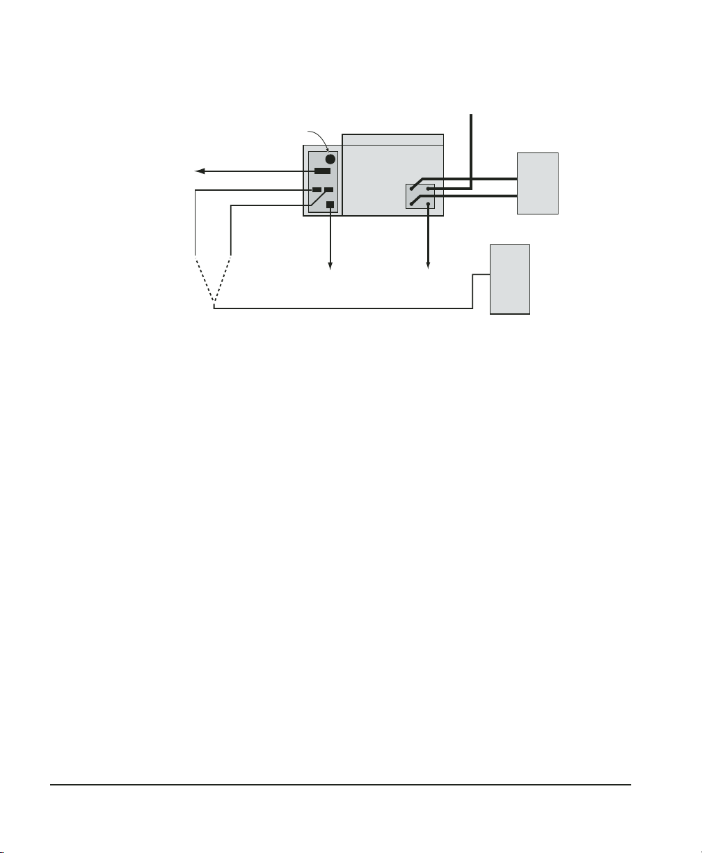
Analog
outputs
Cooling fan
Reference port
Controller port
Humilab
(rear view)
Dry air input (optional)
Neslab
Chiller
(optional)
Inst
allation
Place the
Humilab at its
operating site
Carefull
room behind the unit to make the necessary gas, drain, and
optional chiller connections on the back panel. The two data cables
(an RS-232 cable and an analog output cable) can also be installed
at this point.
Connect
a dry
gas source
(optional)
A dry gas source can be utilized to impro
desiccant material and provide the user with less frequent desiccant replacement.
The HumiLab does not require an external dry gas source to
operate. The unit is equipped with a desiccant cartridge that
provides the Humilab with a –40°C dew point dry gas. The unit is
designed to operate for approximately 24 hours of continuous
usage (at an ambient humidity less than 50%) before having to
replace the desiccant.
AC power
y move the Humilab to its intended site. Leave enough
Drain
Figure 1 — System interconnection diagram
PC
ve the longevity of the
Page
Gas r
equirements.
be –40°C or lower for operation over the full specified range.
6
If a dry gas source is used, the frost point should
Use
Chapter 1 — Installation and Initial Setup
clean, oil-free gas, regulated at 1 to 2 psig at 5 lpm (minimum).
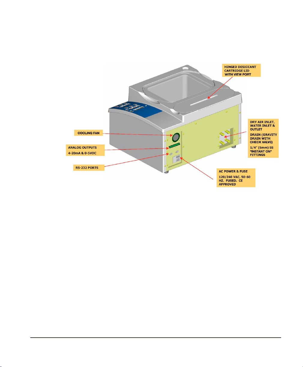
Connect the dry air or dry nitrogen source using the 1/4”
“instant-on” DRY AIR IN connector on the rear of the unit. See
Figure 2, Humilab Rear View.
Figure 2 — Humilab rear view (gas, A/C, and signal connections)
Chapter 1 — Installation and Initial Setup Page 7
Electrical connections
s
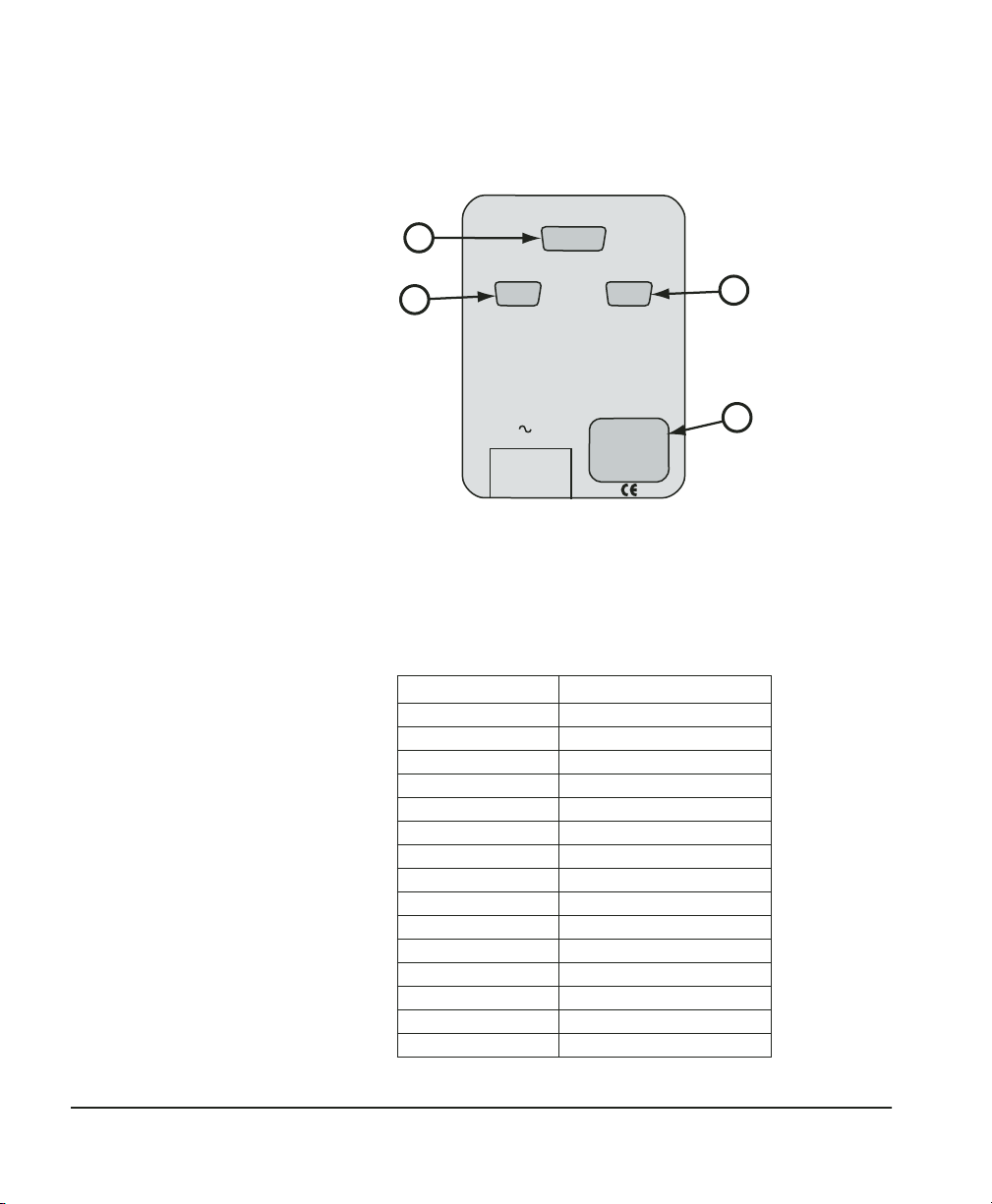
Electrical connections to the Humilab are made on the rear panel
as shown in Figure 3.
A
B
ANALOG OUTPUTS
REFERENCE RS-232 CONTROLLER RS-232
LINE
Figure 3 — Humilab electrical connection
C
D
A. Analog outputs. Analog outputs are available to the operator via
the DB-15 connector located on the rear I/O panel. A cable suitable
for connecting to a terminal block is included. The connector
pinout is listed below.
DB-15 Pin No. Function
1 RH 4–20 mA (+)
2 RH 0–5 V (+)
3 Temp 4–20 mA (+)
4 N/C
5 Temp 0–5V (+)
6 Status
7 N/C
8 N/C
9 Service
10 Gnd (Rtn)
11 N/C
12 N/C
13 N/C
14 N/C
15 N/C
Page 8 Chapter 1 — Installation and Initial Setup
B. RS-232 Reference Port. This connector is used for diagnostics
s
when the LOOP switch is in the OPEN LOOP position. In CLOSED
LOOP mode, it transmits the digital outputs of the hygrometer: dew
point, temperature, and RH.
C. RS-232 Controller Port. This connector is used when down-
loading humidity profiles from Prostep into the HumiLab.(see
Chapter 3).
D. AC receptacle. The AC input power is connected to the power
receptacle. The input voltage is noted on the label to the right. The
input voltage is configured at the factory and must be determined
prior to shipment.
Power Requirements 103–127 VAC
48–66 Hz, 80 VA max
Fuse Type 1A Type T .5A Type T
E. Cooling fan (not visible). The fan is used for cooling the elec-
tronics. The fan must stay clean and clear of any obstruction to
prevent damage to the internal electronics.
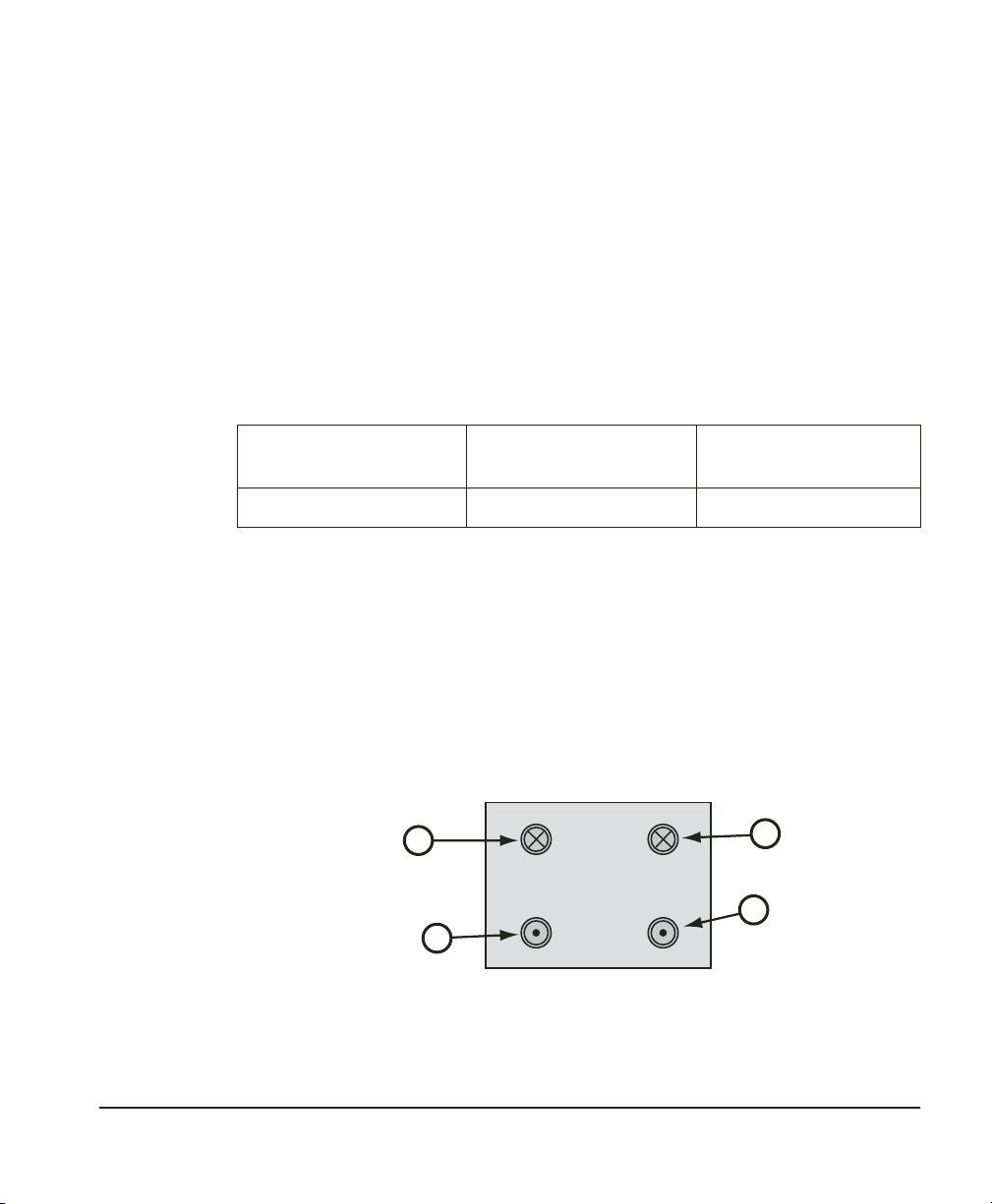
Rear input/output fitting connections
Mechanical connections to the Humilab are made on the rear panel
as shown in Figure 4.
B
COOLANT IN DRY AIR IN
COOLANT OUT DRAIN
C
Figure 4 — Humilab mechanical connection
198–264 VAC
48–66 Hz, 80 VA max
A
D
Chapter 1 — Installation and Initial Setup Page 9

A. Dry air in. A dry air supply can be connected to this port. The
dew point of the dry air must be at or below –40°C for proper
full-range operation. The flow rate requirement is 1 to 2 psig at 5
liters per minute (minimum). If a dry air supply is not available,
then this port must be left open to the atmosphere. The internal
pump will draw the ambient air through the desiccant cartridge to
supply the HumiLab with the proper supply of dry air.
B. Coolant In. For optimum performance, an optional temperature
bath/circulator should be connected to provide a stable water and
chamber temperature. Connect the chiller’s output port to this
Coolant In port.
C. Coolant Out. Connect the temperature bath/circulator’s input port
to the coolant-out port of the HumiLab.
D. Drain. This port allows the operator to easily drain the saturator
before transporting or storing the unit. Simply place a 1/4” tube
into a bucket and press the other end into the drain fitting until it
stops. Water will immediately begin to drain into the bucket. To
remove the tube from the fitting, depress the black outer ring and
pull out the tubing. A built-in check valve prevents water from
running out of the drain port when the tubing is not in place.
Coolant
connections
Page 10 Chapter 1 — Installation and Initial Setup
The HumiLab is equipped with 1/4” “instant on” coolant fittings
that require no tools for installation. These fittings will accept many
types of hard-wall tubing such as Teflon, stainless steel, or
Impolene. To insert the tubing, simply press the tubing into the
connector as far as it will go. Pull gently on the tubing to ensure
the connections are secure.
To remove the tubing from the “Instant On” fittings, simply depress
the black outer ring and pull the tubing out. The coolant fittings
are equipped with built-in check valves that enable the operator to
easily remove the coolant lines with minimal fluid loss.
If the optional chiller is used to accurately control the chamber
temperature, connect the chiller output to the “Coolant In” fitting
on the HumiLab and connect the chiller inlet to the “Coolant Out”
fitting.

Initial setup and water fill
Distilled water is recommended for trouble-free operation. Always
add water with the power turned off (the water level may pulse up
and down during normal operation). After the water chamber has
been filled (or refilled), allow sufficient time (typically one hour) to
equilibrate the water temperature.
1. Set up the unit on a flat surface.
2. Pour in one gallon of clean distilled water.
3. Install the drain line in the rear drain port, and drain out
enough water (about one cup) to ensure that the drain line is
full of water. This procedure is needed for proper water level
indication.
4. Remove the drain line and pour in an additional 1¼ gallons of
distilled water. Wipe up any spillage.
5. Install the dry line, connecting to a source of dry air, if available (–40°C DP dry air or nitrogen, 15–16 psig, 4–5 l/m flow).
If running from a desiccant cartridge, make sure the cartridge
is fully seated and the desiccant color is a minimum of 75%
blue throughout the length of the tube. Replace the cartridge
or desiccant if necessary.
6. Install the unit’s cover.
7. Install the power cord and turn the unit on. Set the controller
to 80–90% RH.
8. Check the water fill level indicator and make sure the level
has not increased above the fill line and that the overflow line
does not leak water (front left-hand corner of unit). If the
water fill level rises sharply or the overflow tube leaks, check
the wet gas tube inlet ports for obstructions.
9. Run the unit for 15–30 minutes and inspect for the absence of
water in the bottom of the wet line ports located at the bottom of the tank I/O block (near 1111H sensor). If water is
present, soak it up with a cotton swab or absorbent cloth, napkin or towel.
10. Perform mirror cleaning and balance procedure as described
in “Mirror maintenance” on page 36.
Chapter 1 — Installation and Initial Setup Page 11
Chilled mirror setup
The GE General Eastern HumiLab is shipped with the chilled
mirror sensor (1111H-SR) and temperature probe (T-100) already
installed.
Initialize the
dew point
sensor
Although it was initialized at the factory, the dew point sensor
bridge should be initialized again to compensate for any change
during shipment. This is accomplished by cleaning and balancing
the sensor as described below. Figure 7, shows the location of the
switches and LEDs on the front panel. Chapter 2 contains a
complete description of the operating procedures.
Figure 5 — Front Panel Controls
1. Plug the A/C power cord into a wall socket.
Page 12 Chapter 1 — Installation and Initial Setup

2. Turn ON the power switch located on the back right side of
the Humilab near the bottom.
The digital LED displays will light, and the generator will go
through a self check cycle. The letter “P” (for Pacer®) will be lit
on the front panel (C in Figure 5). (See Appendix B, page 45
for information on the Pacer feature.)
3. Wait for the Pacer cycle to complete (approximately three
minutes).
4. On the front panel, set the LOOP switch (K) to the CLOSED
LOOP position. (Depress the top of the rocker switch, toward
the filled circle.)
Clean and
balance the
dew point
sensor
The next steps are required to clean and rebalance the dew point
sensor. This normalizes the system, and prepares it for proper operation.
1. Press the SENSOR switch (F) to the HEAT position.
2. Open the test chamber cover and remove the white dust
cover.
3. Locate the sensor cleaning solution (in the GE General Eastern Maintenance Kit). Wet a cotton swab with the blue cleaning solution, and rub it lightly over the mirror. Lightly buff
the mirror dry with a clean, dry swab. Note: If you don’t have
the supplied cleaning solution, a solution of two parts rubbing alcohol to one part distilled water may be substituted.
4. Replace the sensor cover. Be sure that the cover is installed so
that the sensor balance screw aligns with the hole in the
cover.
Do not attempt to operate the sensor without the cover. It is
an optical device and will be offset by overhead light.
5. A vertical LED light bar indicates balance status. Either 3, 2, 1,
or zero horizontal bars will be lit. Locate the Balance, or Bias,
adjustment screw at the top of the sensor. See Figure 6. Using
the small screwdriver supplied in the maintenance kit, slowly
rotate the screw until only the bottom bar is illuminated. (The
Chapter 1 — Installation and Initial Setup Page 13
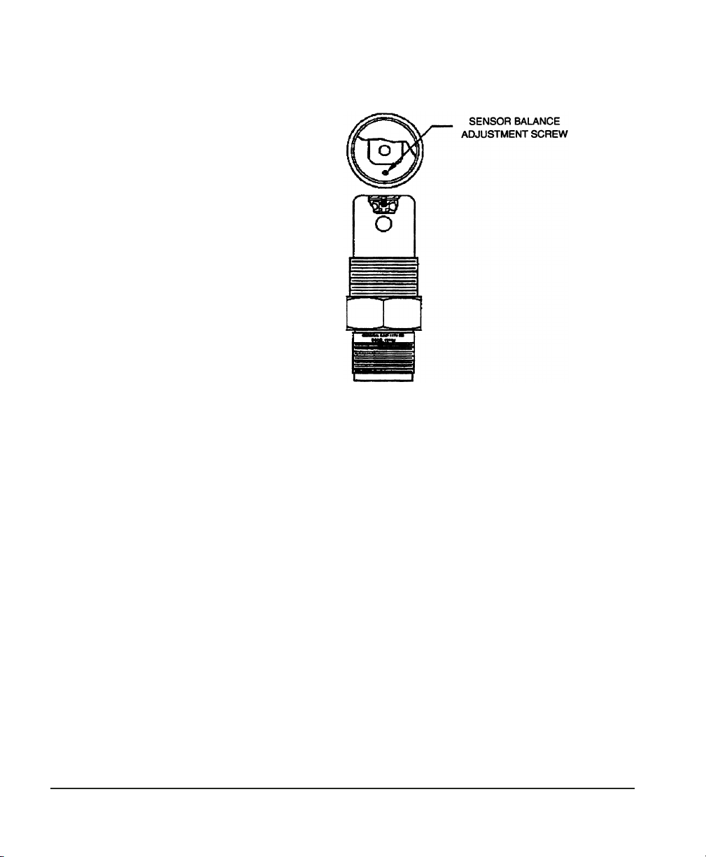
number of bars is increased when you turn the screw counterclockwise.) The optical bridge has now been balanced.
Figure 6 — 1111H Sensor Balance Adjustment Screw Location
6. Place the HEAT switch back in the OPERATE position.
7. Run the instrument through another Pacer cycle. (Momentarily press the INITiate switch.)
The letter “P” will light, and the displays will be frozen for several minutes as the cycle proceeds. At the end of that time,
the “P” will go out, and the left-hand displays will read the
actual percent R.H. and temperature in the test chamber.
8. Use the SETPOINT switch to select 30% RH by pressing on the
upper or lower side of the switch as required.
The display will scroll, one decade at a time, to the desired
reading. Release the switch when that point is reached.
9. Run the chamber for at least one hour, until the water surrounding the chamber assumes ambient laboratory temperature and the temperature equilibrates to ±0.2°C or better.
10. Use the SETPOINT switch to select 00.0 %RH and allow 30 to
45 minutes for the chamber to dry down.
Page 14 Chapter 1 — Installation and Initial Setup

Shipping the Humilab
This procedure describes the process the customer should follow
before shipping the HumiLab to an off site location or shipping the
unit back to GE General Eastern.
1. Remove A/C power from the unit and disconnect the dry gas
supply.
2. Connect a 1/4" O.D. drain line to the drain port located in the
rear of the unit. For customer convenience, an impolene drain
line is provided. Otherwise any 1/4" hard wall tubing will do.
3. Visually interrogate the unit through the fill port to determine if all the water has been removed. If water is still visible,
then the unit may have to be tilted towards the back and to
the left with the drain tube still attached.
4. The temperature bath/circulator lines need to be drained
prior to shipment. Insert the drain tube provided into the
COOLANT OUT port connector. Insert a short 1/4" tube into the
COOLANT IN port connector. This will allow the coolant to be
removed from the temperature coil. This will prevent the temperature coil from freezing during transport and possibly
causing damage to the unit. A slightly pressurized air line
could be used to help facilitate the draining process.
5. Place the mix tray inside of the chamber and fill the chamber
with bubble-pak to prevent any sensor damage and keep the
tray from moving during shipment. Place the cover on top.
Place the rubber stopper (supplied) into the fill port located at
the top front left corner.
6. Place the HumiLab into the transportation case (supplied).
The unit is now ready to be transported.
Chapter 1 — Installation and Initial Setup Page 15

Introduction
Chapter 2 — Operation
The Humilab is very simple to operate. Minimal operator training is
required for successful calibration of humidity recorders, transmitters, or hand-held portables. Typically, only the R.H. setpoint
selector switch is used in a calibration. All other switches are set as
desired and then left in position.
Front panel switch settings are described in this chapter. More
detail is available in Appendix B. For quick reference, the following
settings are typical for most applications:
• Power Switch: ON (mounted on rear of unit)
• Sensor Switch: OPERate
• Display Switch: OPERate
• Loop Switch: Closed Loop (Set to the filled-in circle) for operation; Open Loop (open circle) for uploading profiles
• Balance Switch: Center position
• Auto/Cal Switch: OPERate
• Setpoint: Set to desired chamber humidity
Page 16 Chapter 2 — Operation
Front panel displays and switches
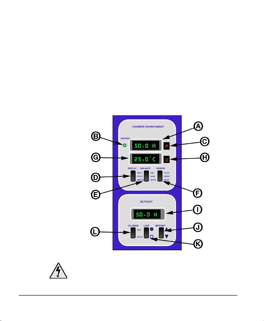
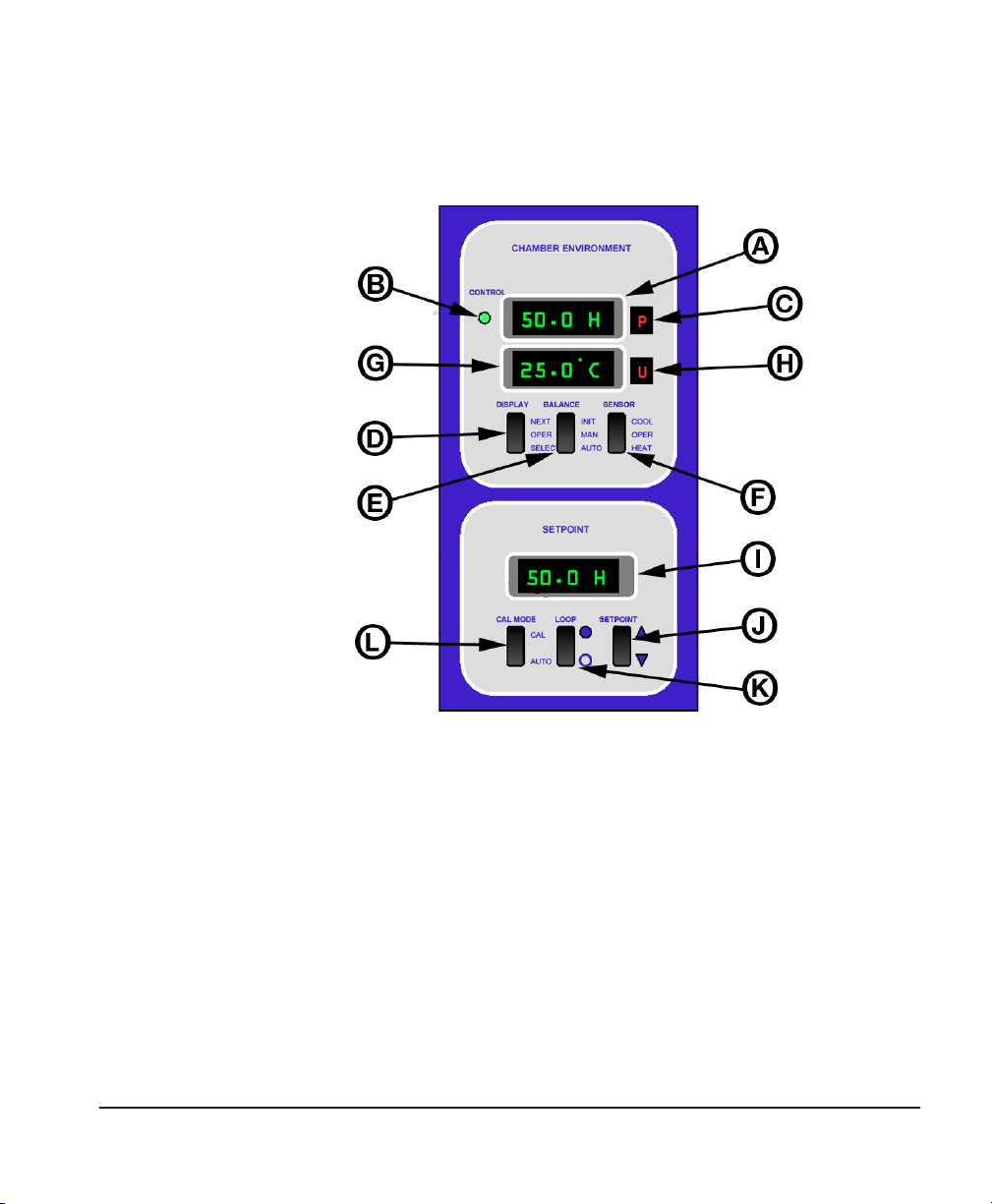
Refer to Figure 7 as you review the following descriptions of the
front panel displays and selector switches.
Figure 7 — Front Panel Controls
The Humilab, as shipped, is set up by the factory for normal operation. The two upper digital displays read Percent RH and Temperature in °C. The lower digital display shows the desired chamber set
point.With the exception of the setpoint selector switch, the other
front panel switches are seldom used in day-to-day operation.
However, they are included in case you wish to make changes to
normal default operation and for system testing.
Appendix B contains information on changing factory-set defaults.
A. HUMIDITY Display. This display is shipped from the factory set
for percent relative humidity. Please refer to Appendix B for more
information.
Chapter 2 — Operation Page 17

If you wish to perform dew point calibrations in the test chamber,
the display may be reprogrammed to read dew point.
B. CONTROL STATUS Indicator. The green control indicator advises
you that the control loop that maintains the dew layer on the
chilled mirror is operating correctly, and that there is a proper layer.
When lit, you may consider it to be an indication that the chilled
mirror humidity measurement is valid. Conversely, if the green
indicator is not lit, you should wait until it lights before performing
calibrations.
C. STATUS Window (humidity). A green letter “S” (for Service) in this
window advises the operator that the sensor mirror has become
contaminated, and requires cleaning.
If you are readjusting the sensor optical balance, a light bar appears
in this window. See “Balancing the sensor optics” on page 37 for
details.
This window will show various indications while reprogramming
the display units or analog outputs. See Appendix B.
D. DISPLAY Switch. The DISPLAY Switch is normally used in the
center OPERate position.
This rocker switch is used to reprogram measurement units and to
check the scale factor of analog outputs.
In the standard configuration, the analog output scale factors can
only be changed using the RS-232 port, to ensure that they are not
changed accidentally. If you wish to reconfigure the system so that
these parameters can be changed via the front panel, see Appendix
B.
E. BALANCE Switch. This switch is normally operated in the lower
AUTOmatic position.
In the AUTO position, the instrument will go through a normal
Pacer® cycle every 12 hours, rebalancing the dew point sensor
bridge and determining whether it requires cleaning.
In the MANual center position, there will be no automatic Pacer
cycles, only those initiated manually (if desired).
Page 18 Chapter 2 — Operation

In the manual position, you will never see the “S”ervice light displayed, telling you that the sensor mirror needs cleaning.
The upper (INITiate) momentary position manually triggers a Pacer
cycle.
F. SENSOR Switch. The SENSOR switch is typically kept in the center
OPERate position.
This switch allows you to over-ride the automatic mirror control
loop, and force the mirror temperature up or down, causing it to
heat or cool. These are test positions used for sensor diagnostics.
G. TEMPERATURE Display. As shipped from the factory, this display
reads temperature in °C. It may be factory or field programmed to
read °F if desired. See Appendix B.
H. STATUS WINDOW (Temperature). This window provides the oper-
ator with programming status for the Temperature display when
programming Units or Outputs. See Appendix B.
I. SETPOINT Display. This display window shows the relative
humidity setpoint that has been programmed in the chamber.
J. SET (SETPOINT) Switch. This switch allows you to select a
humidity setpoint in the display window. Scroll to the desired value
by incrementing or decrementing, one decade at a time, until the
desired value is reached.
K. LOOP SELECT Switch. This selector is normally kept in the Closed
Loop position (up, toward the filled-in circle).
In the Closed Loop position the chilled mirror hygrometer controls
the chamber relative humidity. In the Open Loop position, you can
download humidity profiles from the Prostep software program,
and you can perform diagnostics if necessary (see Chapter 3).
L. CAL/AUTO Switch. This switch is typically kept in the center posi-
tion.
When this switch is pressed into the momentary CALibrate setting,
the system begins the automatic 9-hour recalibration cycle.
Chapter 2 — Operation Page 19

If you ever accidentally switch the Humilab to the “CAL” mode,
simply shut the power OFF and then ON using the power switch
(on the rear panel) to reset to normal operation.
Performing routine calibrations
The unit has been calibrated at the factory. Field calibration is only
required if the measured humidity deviates from the setpoint
humidity by more than 1% RH after one hour.
With the selector switches preset to the proper positions for normal
operation, calibration may be performed as follows:
1. Insert the item(s) to be calibrated into the Humilab humidity
chamber. Run power cables via the top cover to the transmitter.
2. Select the proper RH Setpoint.
When this switch is held up (for higher humidity) or down (for
lower humidity), the digital set point display will scroll toward
the desired set point. First the least significant decade will
change, and then successively more significant decades will
change. Release the switch when the desired humidity is reached.
It may be easier to stop a few counts before the desired reading,
and allow the least significant unit display to move in 0.1%
R.H. steps to the set point.
3. Allow 40 to 60 minutes equilibration time.
The R.H. in the Humilab cavity will gradually move toward the
set point. For the first 20–30 minutes, there will be no
closed-loop feedback. After the loop is controlled, a correction
will be made every 5 minutes.
4. Calibrate as required.
Relative humidity is a function of temperature as well as moisture
content. If you are calibrating a device (such as a humidity transmitter) that generates heat, locate it near the center of the cavity.
This will allow the HumiLab’s temperature sensor to quickly
sense the temperature change and correct for it.
Page 20 Chapter 2 — Operation

Chamber response time
Due to the large cavity size, typical response time will be approximately 30–40 minutes. At the end of that period, the RH in the test
chamber will be within 1% RH of the set point. After that time, the
two will track each other within the accuracy specification of the
instrument.
Chapter 2 — Operation Page 21

Chapter 3 — Using the PROSTEP software
Introduction
This chapter describes the use of GE General Eastern’s Prostep software to set up a calibration test profile.
Prostep software generates humidity/temperature profiles to
control the Humilab. It is supplied with the Humilab system on a
CD-ROM. Using Prostep, a complete automatic test profile (relative
humidity vs. time, with ramps and step changes) may be created
using an IBM-compatible computer. The profile may then be used
for automatic calibration of the devices in the Humilab cavity. See
Figure 8 for a sample humidity profile.
In addition to creating humidity profiles for use in the Humilab,
the PROSTEP software can be configured to generate temperature
control commands/profiles to the recirculating water bath chiller,
remotely operate the Humilab, customize the Humilab calibration
sequence, and collect humidity and temperature data from the
reference hygrometer. This section will detail the creation,
uploading, and operation of humidity profiles and datalogging
features only. Consult the factory for more advanced operational
detail.
Figure 8 — Sample Humidity Profile
Computer
requirements
Page 22 Chapter 3 — Using the PROSTEP software
Prostep requires a computer system with the following characteristics:

• IBM-compatible 286 or higher machine
• RS-232 serial port
• at least 512K of RAM
• at least 1Mb of hard disk space
A DB-9 male to DB-9 female cable is supplied, along with a standard
RS-232 cable and null modem adapter.
If your computer has only USB ports in place of serial comm ports,
you will need to use a USB-to-serial converter, available from
computer supply houses.
Computer
communication
port settings
Connecting the
host computer
Set your IBM compatible computer’s serial communications port
settings as follows. (In Windows, go to Settings, control panel,
system, device manager, ports, communications port, port settings)
Bits per second: 1200
Data Bits: 8
Parity: None
Stop Bits: 1
Flow Control: None
Controlling Humilab. For communication to the Humilab controller
(uploading/downloading humidity profiles), connect the host
computer COM port connector to the 9-pin RS-232 CONTROLLER
connector on the rear of the Humilab.
Datalogging. For datalogging with PROSTEP, connect the host
computer COM port connector to the 9-pin RS-232 REFERENCE
connector on the rear of the Humilab. The Humilab must be in
closed loop operation.
Installing the Prostep software
Load the supplied CD-ROM and open the folder containing the
software. Double click on SETUP.EXE and follow the on-screen
directions.
Chapter 3 — Using the PROSTEP software Page 23

Running Prostep
To start the program, click on start, Programs, Prostep, and
Prostep.
Screens shown in this manual represent the appearance of Prostep
running under Windows XP, and will differ with other operating
systems.
Note: The HumiLab’s LOOP switch must be in the OPEN LOOP posi-
tion (open circle) when uploading Prostep humidity profiles. It
must be in the CLOSED LOOP position (filled-in circle) to run a
profile in normal operation.
PROSTEP
communication
settings
The profile
screen
Prior to communication with the Humilab, verify the communication settings in PROSTEP. Under Options > Communications Setup,
verify the following:
Baud rate: 1200
Flow Control: Off
Stop Bits: 1
Data Bits: 8
Com Port: 1–4 (matched to host computer)
Parity: none
The main profile screen is used for entering and modifying the
Humilab’s humidity profile. A profile must be uploaded to the
Humilab before it can be used, and can be downloaded back into
the PC for further editing. Use the File menu to manage the loading
and storing of multiple profiles. To customize the profile display,
see the Options / Scale Graph menu below.
The profile is specified by a number of setpoints. Each setpoint
specifies a bath temperature (if configured) and a programmable
humidity ramp as shown in Figure 9. Six items may be specified for
each setpoint:
Page 24 Chapter 3 — Using the PROSTEP software

D
20°C
40% RH
C
SETPOINT
Temp
3
B
30°C
E
80% RH
R.H.
F
time
A
A setpoint sequence number
B bath temperature
C an optional delay before the humidity
change is initiated (to allow for temperature
stabilization)
D initial humidity
E final humidity
F duration of the humidity ramp
Figure 9 — A typical setpoint and its values
Click on the large up and down arrows on the screen to step
through the list of setpoints, and enter the data for each setpoint.
The File menu
The File menu accesses standard Windows functions for:
• creating a new profile
• loading a existing profile
Chapter 3 — Using the PROSTEP software Page 25

• saving the current profile
• saving the current profile under a new name or file format
• selecting a folder for holding the profile data or datalog file
• exiting the program
The Run menu
The Options
menu
The Run menu contains the following choices:
Run Profile. Runs the profile most recently downloaded to the
Humilab.
Collect data. Collect RH, temperature, and/or DP data for Humi-
Lab operation. (See options > Setup Datalogging Parameters).
Halt Test. Stops running the current profile.
The Options menu accesses all of the setup and configuration
items:
Scale Graph. Sets the parameters for the main screen profile
display:
• units and maximum/minimum values for humidity and temperature (units set to %RH for typical Humilab profile)
• time scale
Page 26 Chapter 3 — Using the PROSTEP software

• graph colors.
Set up Communications. Sets the comm port parameters:
• baud rate: 1200
• flow control: None
• stop bits: 1
• data bits: 8
• parity: not checked
• comm port number: 1
Set up Data Logging Parameters. Sets units and formats for
logged data.
Before using this screen, make the following settings:
• set Predefined Groups to M4
• set BBox Port to –1
Chapter 3 — Using the PROSTEP software Page 27

A list displays all parameters to be logged, showing all configured
data for each. To change one, select the line with the mouse. Data
from that line will appear in the edit line, above. Make changes and
click on Edit to store the changes. Click on Remove to delete the
selected line. To add a new line, enter the data and click on Add.
When finished, click on Done.
• Unit Number: If more than one unit is connected, each can be
selected for configuration
• Enabled check box: must be checked to allow datalogging
• the Comm Port that the Humilab or BlackBox is connected to
• Channel base Address: default = 48
• Unused Channel Number: the number of the first Black Box
channel that is not in use
• Log Interval: the time between logged items (hh:mm:ss)
• Append to File check box: adds new data to end of existing
file if checked
Page 28 Chapter 3 — Using the PROSTEP software

The Transfers
menu
The Transfers menu allows moving a profile between the computer
and the Humilab.
Upload Profile. Send the current profile from the PC to the
Humilab.
Download Profile. Transfer a profile from the Humilab to the PC
The Help menu
The Help menu supplies on-line instructions for using the Prostep
software.
Chapter 3 — Using the PROSTEP software Page 29

Chapter 4 — Theory of Operation
A
Overview
Divided flow
The Humilab Relative Humidity Generator uses a divided flow
method to accurately generate a selected relative humidity in a
large test chamber. The selected humidity is controlled using a GE
General Eastern Chilled Mirror Hygrometer System. This chapter
describes divided flow and the chilled mirror controller.
The Humilab’s chamber RH is controlled by time proportioning a
fraction of an air stream through a saturator and a desiccant. The
saturated air mixes with the dry air to produce the desired RH
value in the chamber. Figure 10 shows the basic block diagram of
the Humilab’s operation.
-40°C DP
ir supply
(optional)
Desiccant
Cartridge
Dry gas
temperature coil
(surrounding chamber)
Water jacket
Pum
p
Solenoid
valve
Wet
gas
in
Te st
chamber
Figure 10 — Basic Block Diagram
Dry
gas
in
Sparger
(bubbles air
through water)
The operator selects the desired relative humidity on the front
panel, using the increment/decrement switch to scroll to the value.
The selected RH determines the duty cycle of a solenoid operated
Page 30 Chapter 4 — Theory of Operation
wet air/dry air valve.

The time required for one complete cycle of operation is 1 second.
During that period, the on-off duty cycle determines the ratio of
wet air to dry air, which, in turn, determines the percent relative
humidity in the test chamber. When the valve is ON, wet air is
generated and flows into the chamber. When the valve is OFF, dry
air flows into the chamber. Figure 11 shows how the wet/dry air
ratio is proportional to the relative humidity.
Figure 11 — Wet/Dry Air Selection
During the wet air portion of the cycle, the air is thoroughly saturated by an efficient diffuser. It then passes into the test chamber.
During the remainder of the cycle, the dry air enters the chamber,
after having first been completely temperature stabilized so that it
is virtually the same temperature as the water in the jacket
surrounding the chamber. This stabilization ensures that there is
very little temperature gradient between the incoming air and the
chamber itself.
The Humilab chilled mirror controller
A GE General Eastern chilled mirror dew point hygrometer is built
into the Humilab, providing continuous closed loop feedback to
control the relative humidity of the test chamber. This device
provides a fundamental, N.I.S.T. traceable measurement of the
chamber dew point. See Appendix B for more detailed information
on the operation of the chilled mirror hygrometer.
Mounted inside the test chamber is a chilled mirror dew point
sensor, bringing chamber dew point information to the hygrometer.
Chapter 4 — Theory of Operation Page 31

Also mounted within the test chamber is a platinum RTD air
temperature sensor, providing air temperature information (dry
bulb) to the chilled mirror hygrometer. A microprocessor calculation converts the chamber dew point and air temperature data to
percent relative humidity.
A microprocessor-based relative humidity controller receives the
RH information. It also looks at the RH setpoint which has been
selected on the front panel by the operator. If there is a difference
between the two readings, the controller adjusts the ratio of wet to
dry air entering the test chamber, at 5-minute intervals. This closed
loop operation ensures that the resulting relative humidity in the
chamber remains within ±0.2% R.H. of the chilled mirror hygrometer reading.
A multi-point calibration of the test chamber against the built in
chilled mirror has been performed at the factory, at 10% R.H. increments. At each point, a correction factor, determined by the actual
dew point and temperature measurement, has been stored in
non-volatile memory. Thus, the test chamber has acquired the
accuracy and N.I.S.T. traceability of the fundamental chilled mirror
hygrometer. If desired, this automatic calibration of the test
chamber against the chilled mirror hygrometer may be repeated at
any time in the field.
What is optical
condensation
hygrometry?
Page 32 Chapter 4 — Theory of Operation
Optical condensation hygrometry is a precise technique for determining the water vapor content in gases by measuring dew or frost
temperatures. Because these hygrometers are so accurate, they are
widely used as a standard in many of the world’s metrology laboratories.
Optical condensation hygrometry works on the chilled-mirror principle and provides a fundamental measurement of dew/frost point
temperature. A metallic mirror surface is cooled until it reaches a
temperature at which condensation begins to form on it. The dew
layer is optically detected and the mirror is held at that temperature. The mirror temperature, measured with a platinum resistance
thermometer, is an accurate indicator of the dew or frost point.

General
description of
the chilled
mirror
hygrometer
system
The Humilab includes a general purpose chilled mirror dew point
system that utilizes advanced microprocessor control. It is supplied
with GE General Eastern’s patented PACER® (Programmable Automatic Contaminant Error Reduction). See Appendix B, page 62, for
information on the Pacer feature. The Chilled Mirror Hygrometer
System also provides 4-20mA and 0-5 VDC analog outputs and
RS232C communications. For detailed Chilled Mirror Hygrometer
System Specifications, refer to Appendix A.
The Humilab Chilled Mirror System measures humidity in dew/
frost point or relative humidity (RH). It also measures temperature
in °C or °F. It accepts inputs from the Model 1111H chilled mirror
dew point sensor and the Model T-100E temperature sensor. These
are located within the test chamber.
Chilled mirror
hygrometer
system theory
of operation
The Humilab Chilled Mirror System operation is illustrated in
Figure 12 on page 34, which shows the way in which the chilled
mirror hygrometer detects and measures dew point. The condensate detection mirror is illuminated with a high intensity, solid
state, light emitting diode (LED). A photodetector monitors the LED
light reflected from the mirror. A separate LED and photodetector
combination are used to compensate for any thermally induced
changes in the optical components.
The photodetectors are arranged in an electrical bridge circuit, and
the photo-detector is fully illuminated when the mirror is clear of
dew. As dew forms on the mirror, the photodetector receives less
light due to scattering losses. Since the bridge output current is
proportional to the light received, a large bridge current develops
whenever the mirror is dry. The bridge output is amplified and
used to control the direct current to the thermoelectric cooler,
causing the mirror to cool toward the dew point.
As dew begins to form on the mirror, the optical bridge output is
reduced due to a reduction in detected light. This in turn, causes a
decrease in cooling current. A rate feedback loop within the amplifier ensures critical response, and the system quickly stabilizes at a
condition where a thin dew or frost layer is maintained on the
mirror surface (i.e., the dew or frost point). Thus, the mirror temper-
For detailed information on the chilled mirror hygrometer, refer to
Appendix B.
Chapter 4 — Theory of Operation Page 33

Figure 12 — Chilled Mirror Sensor Block Diagram
ature is always at the dew point of the gas being measured, and it
follows the dew point if it changes. A precision thermometer
element embedded within the mirror directly monitors this dew
point temperature and provides a continuous readout to the user.
Page 34 Chapter 4 — Theory of Operation

Chapter 5 — Maintenance and
Introduction
Troubleshooting
There are two levels of maintenance on the Humilab: basic system
maintenance and reference measurement maintenance.
Basic
maintenance
The following should be checked (every few hours, until the
requirements for your particular application determine a different
schedule):
• check the water level surrounding the calibration chamber
• check the desiccant condition and replace if it has turned
pink
Verifying water level. Water should be added to maintain the level
in the green area of the water level indicator. Be sure to use only
distilled water, and be careful not to accidentally spill water in the
test chamber. If you do spill any water, wipe it up completely.
The water level may pulse up and down while the Humilab system
is operating.
Verifying desiccant condition. Prior to each use of the HumiLab,
verify that the desiccant cartridge contains active desiccant material. The desiccant contains an indicating material which turns
from blue to pink as the desiccant is exhausted. Replace or regenerate the desiccant granules before the cartridge is completely
exhausted.
To regenerate the desiccant, the granules may be spread in layers
one granule deep and heated for 1 hour at 210° C or 425° F. The
regenerated material should be placed in the original glass or metal
container and sealed while hot. Do not overheat the desiccant.
Replacement desiccant can be obtained from GE General Eastern.
Chapter 5 — Maintenance and Troubleshooting Page 35

Reference
measurement
maintenance
The following should be performed as required to maintain the
accuracy needed for your particular application:
• periodic mirror cleaning
• balancing the sensor optics
Details for these procedures are given below.
Problems not resolved by these procedures require the attention of
a person with more in-depth knowledge. The chilled mirror
hygrometer sensor (Model 1111H) generally requires the most
attention because it is the most intricate component of the
Humilab. Information addressing these problems is contained in
Appendix B.
Mirror maintenance
Some Humilab owners routinely perform a mirror cleaning before
each calibration run for best possible system operation. While this
is truly optimum, it is theoretically possible (and generally most
practical) to operate until the system tells you that the mirror needs
cleaning by lighting the letter “S” (for Service) in the Status
window.
In normal operation, the green “CONTROL STATUS” indicator on the
left hand side of the front panel will be lit. The Control Status light
tells you that everything is normal with regard to the control loop
that determines the mirror dew layer.
If the Service indicator adjacent to it does light, momentarily activate the Pacer® switch. A letter “P” will appear in a window on the
front panel. If the Service light goes out after several minutes (at
the end of the Pacer cycle), continue normal operation. If the
Service light remains on after the end of the Pacer cycle, it is an
indication that the sensor mirror requires cleaning. A fine layer of
dust or other contaminant has gradually built up on the surface,
and it must be removed.
Cleaning the
sensor mirror
Page 36 Chapter 5 — Maintenance and Troubleshooting
Periodically inspect and maintain the chilled mirror hygrometer
sensor (1111H) optics as described in the following paragraphs.
These procedures can be done at any time but are only necessary

when an “S” appears on the status display, indicating that service is
required.
Under normal conditions, the chilled mirror hygrometer is
self-checking and self-balancing. However, there are occasions
when particulate matter and water-soluble contaminants reduce
sensor mirror reflectance and system accuracy. Clean the sensor
mirror according to the procedure below.
1. Deactivate the sensor cooler by setting the Electronics front
panel Sensor switch to the HEAT position.
2. Open the sensor by removing the sensor cover.
3. Moisten a cotton swab with a cleaning solution suitable for
mirrors, such as the blue cleaning solution in the GE General
Eastern maintenance kit, or dilute methanol or rubbing alco
hol.
Do not use Q-tips or other swabs that contain oils.
4. Clean the mirror with a few light wipes. If the sensor has been
exposed to significant contamination, clean the other optical
surfaces in the sensor and the sensor cavity itself.
5. Replace the sensor cover. Leave it in the Open position, with
the large holes allowing maximum air into the sensor cavity
for fastest response time.
6. Return switches to normal, initiate a Pacer cycle, and continue
operation.
-
Balancing the
sensor optics
Chapter 5 — Maintenance and Troubleshooting Page 37
If the service (“S”) flag reappears after a Pacer cycle, even after
performing the mirror cleaning procedure above, check the sensor
optics balance adjustment. Improper adjustment of the optical
balance is the most common cause of instrument malfunction.
Also, new systems may require an optical balance adjustment after
one or two months of operation.
Never perform the Optical Balance Adjustment without first cleaning the mirror.
Place the sensor switch on HEAT, wait one minute, then observe the
segment display. If only the bottom segment bar is lit, the sensor is
properly balanced. Otherwise, balance the sensor according to the
procedure below.

1. Clean the mirror as described earlier in this chapter. Make
sure you replace the sensor cover when checking the balance.
If no bars are lit or more than one bar is lit, go to Step 2. If one
bar is lit, go to Step 3.
2. If no bars are lit, turn the balance screw on the sensor
COUNTERCLOCKWISE until only the bottom bar is lit.
If more than one bar is lit, turn the balance screw CLOCK-
WISE until only the bottom bar is lit. (For the adjustment
screw, see Figure 6 on page 14.)
Be sure to cover the mirror cavity while adjusting the balance
screw, since ambient light can cause an offset.
3. The sensor is balanced when one bar is lit. Replace the sensor
cover, if necessary, and make sure one bar is still lit. If not,
repeat Step 2, since you were allowing some light to enter the
cavity. Place the Sensor switch back to OPERATE to stop heating the mirror.
4. Initiate a Pacer cycle by switching the Balance switch to INIT.
At the completion of the cycle, the Humilab Chilled Mirror
Hygrometer System is properly balanced. Figure 13 on the
next page diagrams the complete balancing procedure.
Page 38 Chapter 5 — Maintenance and Troubleshooting

Figure 13 — Mirror Check and Mirror Sensor Balancing Procedure
Chapter 5 — Maintenance and Troubleshooting Page 39

Field
replacement of
the sensor
mirror
One advantage of using a GE General Eastern chilled mirror dew
point sensor is you can replace the mirror yourself. A sensor does
not have to go back to the factory for replacement of the reflective
surface, but of course you can return it for factory service if
desired. A mirror may require replacement for these reasons:
• The reflective surface may be gradually abraded by sharp par-
• The mirror surface may be accidentally scratched or gouged
Replacing the sensor mirror. Required equipment: Torque driver, set
to 20-30 inch-ounces of torque. You can order a GE General
Eastern type TW-1 torque driver if needed.
1. Open the sensor by removing the sensor cover.
2. Unscrew the old mirror, using a 3/16-inch (0.187) hex socket.
3. The kit supplied by the factory contains the replacement mir-
4. Use a toothpick or similar tool to place a small amount of
5. Carefully screw in the new mirror and tighten to the proper
6. Carefully clean the mirror surface, using a cotton swab and
7. Replace the cover and return the sensor to normal operation.
ticles.
during use or cleaning.
Discard the old mirror.
ror and a container of white thermal compound for proper
heat transfer. Complete instructions are also included in the
kit.
thermal compound in the hole into which the mirror is tightened. (Do not apply the compound to the mirror stem.) Do
not use an amount large enough to leak out when the mirror
is tightened. Do not allow any compound on the mirror surface, as it is very difficult to remove completely.
torque.
The mirror protrudes only about 1/16-inch above the surface.
Ensure that the hex socket does not slip off while tightening, as
this may mar the new mirror or mar the vapor barrier.
the cleaning solution supplied in the maintenance kit. Alternatively, you can use distilled water or diluted rubbing alcohol.
Under some circumstances, a new mirror may operate in a
somewhat unstable manner for the first one to two hours.
Page 40 Chapter 5 — Maintenance and Troubleshooting

Annual recertification
A dated Certificate of Conformance has been supplied with the
Humilab system from the factory. This document indicates traceability to the National Institute of Standards and Technology
(N.I.S.T.), in Gaithersburg, MD, USA. Under most regulatory standards, this certification is good for one year from date of issue. If
your regulations require that the Humilab be re-certified annually,
there are two methods you should consider.
• Return the unit to GE General Eastern for re-certification
• Have it re-certified in your standards laboratory if adequate
traceable standards are available.
Troubleshooting the Humilab, system diagnostics
Is the system
operating
correctly?
The Setpoint display (lower right) shows the R.H. that you have set
the test chamber to. The Humidity display (upper left) shows the
actual R.H. in the chamber, as read by the chilled mirror hygrometer. Do they agree within the instrument specifications?
Set Point RH and Actual RH do not Agree within Specifications.
Actuate the setpoint select switch. You will instantaneously get a
reading in the Setpoint display window that is the actual value
needed to generate the previously displayed setpoint. That is, it is
the R.H. value selected by the SETPOINT switch (plus or minus a
correction value).
Set Point RH and the Corrected Reading Differ by more than 5%.
Check the following to determine the source of the problem.
• Is a green letter “S” illuminated in the window to the right of
• Did you fill the reservoir with water and run a calibrate cycle
the Control Status light?
If so, the mirror needs cleaning due to buildup of dust on the
surface. See mirror cleaning instructions earlier in this chapter.
without an adequate waiting period for the water temperature
to completely equilibrate to ambient?
Chapter 5 — Maintenance and Troubleshooting Page 41

If that is possible, run it again with a stable water supply.
• Relative humidity is a function of temperature. Are you calibrating devices in the chamber that generate heat?
If you are, try to locate the heat producer adjacent to the temperature sensor in the center of the chamber. This way, the system
will correct for it automatically.
• Is the green Control Status indicator off?
If so, the chilled mirror is not tracking the chamber. See the section on page 59 in Appendix B on chilled mirror hygrometer
system troubleshooting.
Page 42 Chapter 5 — Maintenance and Troubleshooting

Appendix A — Specifications
% RH range 10 to 90% RH at 77°F (25°C)
Temperature range 68 to 86°F (20 to 30 °C) May be used with Tempera-
ture-Controlled Water Bath/Circulator. Humidity limited by
surface temperature of internal walls and cover (dew point
in chamber must be less than interior surface temperature
to avoid condensation).
Response time 10 minutes for 63% step change. 30–40 minutes to full
stability
Accuracy ±1% RH from 10% to 70% RH
±1.5% RH from 70 to 90% RH
±0.3°F (0.15°C) dew point at 77°F (25°C)
±0.3°F (0.15°C) dry bulb at 77°F (25°C)
Analog outputs Two (humidity and temperature), each user-scalable,
4–20mA/0–5VDC
Power 115 or 230 VAC ±10%, 50/60Hz single phase
Digital interface Two RS-232 ports for reference and generator interface
Prostep software Windows 95/98 or above required. Supplied on CD ROM
with Operator’s Manual (PDF) and HCON Humidity Conversion Software.
Approvals CE approved. Certifications supplied: Certificate of NIST
traceability and functional test data
Display Three LEDs, 0.5" (1.3cm) high, 7-segment
Shows Set Point (%RH), Actual % RH, and Temperature
0.1% RH/°C/°F resolution
Workspace dimensions 11" by 9" by 6.5" (28 by 23 by 16.5 cm)
Approx. 644 in3 (10.6 liters)
Overall dimensions 23"L by 19"W by 13"H (58 by 48 by 33 cm)
Appendix A — Specifications Page 43

Materials Chamber: stainless steel
I/O block: aluminum
Water jacket: stainless steel
Water capacity 2.2 gallons (8.3 liters)
Mechanical I/O Fill port
Fittings: 1/4" OD tubing, instant-on fittings for: water circulation (inlet and outlet); water drain (for gravity draining);
and dry air inlet (compressed dry air to be regulated to < 5
PSI)
Weight 66 lbs (30 kg) dry weight
Electrical I/O Power: IEC receptacle
Analog outputs: DB-15
RS-232: DB-9
Water capacity indicator Liquid sight glass – color keyed indicator
Desiccant Indicating type (bright blue when dry; pink when satu-
rated). Chamber runs 24 hours at 50% RH and 77°F (25°C)
on a new charge of desiccant. Dry compressed air (–40°F /
–40°C Dew Point or drier) extends life indefinitely.
Page 44 Appendix A — Specifications

Appendix B — Humilab chilled mirror
hygrometer details
Introduction
A general description of the Humilab chilled mirror is presented in
Chapter 4. In most installations this general description is
completely adequate. However, some applications may require
system modification to meet specialized needs. This appendix
describes how to make these changes. It also provides more
detailed information on the Humilab mirror system, its maintenance, and troubleshooting.
Because of the delicate and critical nature of the chilled mirror
components, this information is intended for trained electronics
technicians. If you are not comfortable performing procedures in
this appendix, contact GE General Eastern for assistance.
Chapter
organization
This is a large appendix consisting of the following sections:
• A list of the Humilab Chilled Mirror System Components
• Front Panel Operation
• Using the DISPLAY Switch to Set Defaults (Select Options)
• RS-232 Communications (Windows Terminal Program)
• Using RS-232 Communications to modify Humilab Operations
• Output Terminal Connections
• Service and Troubleshooting Procedures
• Helpful Hints
System components
The Humilab chilled mirror system consists of the following items:
• Electronics Module (as part of the Humilab)
Appendix B — Humilab chilled mirror hygrometer details Page 45

• A dew point sensor (GE General Eastern Model 1111H)
• A Temperature Sensor (GE General Eastern Model T-100E)
• Interconnecting cables (part of the Humilab)
Front panel operation and displays
The front panel was discussed in Chapter 2 from a daily operations
standpoint. This section repeats some of this information (for quick
reference), but also supplies additional information.
Figure 7 on page 17 shows the front panel layout. The panel
contains digital dew point and control status displays and three
operating switches: SENSOR, BALANCE and DISPLAY. The lettered
sections below correspond to the labels in page 17.
A
B,C
D
E
DEW POINT display — The DEW POINT display shows the dew or frost point in
Celsius or Fahrenheit units.
CONTROL/STATUS display — The CONTROL/STATUS display includes a green
control light and a seven-segment display. The control lights comes on when
the system detects both a stable dew or frost layer and a stable dew point
temperature. The seven-segment display indicates as follows:
P
Programmable Automatic Contaminant Error Reduction
(PACER®) mode or Automatic Balance (AUTO) mode is in
operation.
S
Service — The system optics require service, cleaning, or
adjustment.
(bars) Indicates the approximate amount of condensation on the
sensor mirror. (Only seen in HEAT or COOL mode.)
DISPLAY Switch — This is a three-way switch that selects:
NEXT A momentary position used when viewing or changing
OPERATION Normal operation.
SELECT A momentary position used when viewing or changing dis-
played unit, output unit and scaling or alarm units and limits.
BALANCE switch — This is a three-way switch that selects:
AUTO The Pacer/Auto cycle occurs at a pre-selected interval.
Page 46 Appendix B — Humilab chilled mirror hygrometer

MANUAL No PACER cycle unless manually initiated.
INIT
F
SENSOR Switch — This is a three-way position switch that selects:
HEAT Allows the mirror to be cleared of condensation in order to
No PACER cycle unless manually initiated.
check for proper control loop operation.
OPERATION Normal operation.
COOL
A momentary position that forces maximum cooling in
order to check depression capability.
Displays
Main display. The upper display can show R.H. or Dew Point °C or
°F. The front panel DISPLAY switch is used to determine which
parameter is displayed. The factory default for the Humilab is
%R.H. The lower display shows temperature in °C or °F. The factory
default is °C.
Control status display. The CONTROL STATUS display includes a
green control light and a green, seven segment LED display. The
control light comes on when the system detects both a stable dew
or frost layer and a stable dew/frost point temperature. The green
LED can read as follows:
P - Programmable Automatic Contaminant Error Reduction
(PACER®) mode or Automatic Balance (AUTO) mode is in operation.
S - Service. The system optics require service, cleaning, or adjust-
ment.
U - In Units Select mode when using the DISPLAY switch
O - In Output Select mode when using the DISPLAY switch
Horizontal bars indicate the approximate amount of condensation
on the sensor mirror when the SENSOR switch is in HEAT or COOL.
It is an indication of dew layer thickness on the mirror.
See the information starting on page 49 in this appendix for information on using the DISPLAY switch for re-programming Units,
Outputs, or Alarms.
Appendix B — Humilab chilled mirror hygrometer details Page 47

Switches
Display switch. The DISPLAY switch is a three-way switch that
selects:
NEXT - A momentary position used when viewing or changing
displayed units, output units and scaling.
OPER - Normal operation.
SELECT - A momentary position used when viewing or changing
displayed units, output units and scaling.
Display switch operation. The DISPLAY switch is used to change the
units displayed in the main display, view or change units for the
analog output(s). In the Default mode, as shipped from the factory,
the actual analog output scaling can only be modified via the
RS-232 port, to avoid accidentally changing them when changing
displayed units at the front panel. (See “RS-232c re-programming
mode” on page 52 of this appendix.)
Balance switch. The BALANCE switch is a three-way switch that
selects:
INIT - A momentary position that initiates a balance cycle, either
PACER or AUTO.
MAN - No balance cycle unless manually initiated, using INIT.
AUTO - The PACER/AUTO cycle occurs automatically at a
pre-selected interval.
See “Set balance type” on page 54 for details on resetting the balance
interval via RS-232 communication.
Sensor switch. The SENSOR switch is a three-way switch that
selects:
COOL - A momentary position that initiates maximum cooling of
the chilled mirror sensor in order to verify its depression capability.
OPER - Normal operation.
HEAT - An on position that initiates heating of the chilled mirror
sensor in order to clear it of dew or frost and verify proper control
loop operation.
Page 48 Appendix B — Humilab chilled mirror hygrometer

Option selections using the display switch
The DISPLAY switch is used in conjunction with the three green
LED displays (the Units portion of the main display, the parameter
annunciator, and the Control Status display). It has a central rest
position, OPER(ate), and two momentary positions, NEXT and
SELECT. In general, NEXT allows you to get into Option Selection
mode, scroll through various portions of the menu, and scroll
through digits and characters to set values. SELECT allows you to
select which area to access and to set values and characters.
A simplified
explanation of
the option
selection
system
The DISPLAY switch provides you with several main menus. In
sequence, these are:
UNITS on the top display
UNITS on the bottom display
OUTPUTS on the top display
OUTPUTS on the bottom display
Menu navigation.
It’s easier than it might first appear to move about and select
options. Follow the three-step process below.
1. Press NEXT until you see one of the above main menus that
you want. When you get to the one you wish to see, press
Select. This action puts you IN that main menu, and you can
proceed to scroll through it until you see the submenu you
want.
2. When you see it, press SELECT. You are now IN that submenu.
By pressing NEXT, you can scroll through it and find the
parameter you wish to select.
3. When you find the one you want, save it by pressing SELECT.
Indications on the front panel will guide you. It may sound
complicated, but once you have done it a few times, it will
seem very logical.
It is suggested that you now proceed to try it intuitively. The indicators will help you, and you may not need to use the manual. If
you do run into trouble, consult the following sections.
Appendix B — Humilab chilled mirror hygrometer details Page 49

• To begin programming the Electronics Module, press the DIS-
PLAY switch to NEXT. (You may have to keep the switch
pressed for 1-2 seconds in order to see a change.)
• The Electronics Module will leave Operate mode, enter Program mode and display the first of the three main functions.
While you are programming the Electronics Module, it will not
display or output measurement data.
• Press NEXT to display the next menu or option.
• Hold the switch in the NEXT position to scroll through all the
options available. When you get to the end, the Electronics
Module will return to Operate mode.
• Press SELECT to access the displayed function or accept a setting displayed on the main display.
The following two sections map out the functions available in
Program mode along with the state of the three green LED’s at each
step.
• N will display the next function or scroll through alphanumeric values. Depress NEXT for 1-2 seconds
• S will access a function or accept a new value. Depress NEXT
for 1-2 seconds
A more
rigorous
explanation of
The following description describes the DEFAULT programming
sequence for a unit as shipped from the factory. If the behavior of
the DISPLAY switch has been modified, using the RS-232C port, the
description may not be accurate.
the option
selection
system
Page 50 Appendix B — Humilab chilled mirror hygrometer
Default operation.
• From OPERATE mode, Press N.
• The main display and parameter annunciator blank, and the
CONTROL STATUS display shows “U” in the upper display. If
you press S, you can scroll through all the parameters available for display and select one. For now, press N. You can now
do the same for the bottom display.
• The CONTROL STATUS display shows “O”, and the parameter
annunciator shows “Humidity.” If you press S, you can view

the parameter for the Humidity output and the scaling. For
now, press N. You can now do the same for the bottom display.
The units that you can select in the Units mode are shown in Table
7:
Display Units Parameter Flag Explanation
°C Humidity Dew Point, °C
°F Humidity Dew Point, °F
H Humidity Relative Humidity,%
°C Temperature Temperature, °C
°F Temperature Temperature, °F
Table 7: Electronics Module Unit Selection
When you see the parameter you want to display, press S to select
it. You can have the Electronics Module display a subset of its
default parameters. See the RS-232C communications information
in Appendix C for details.
• The CONTROL STATUS display now shows “O.” Press S to view
the output(s). The CONTROL STATUS display shows “Humidity.” The current high value for the humidity output is shown.
Press N to view the low value. Press N again. You will then be
able to view the high and low values for the Temperature output. When you are done, press N to move on.
Changing output(s). You can modify the behavior of the DISPLAY
switch so that the output units and scaling ON/OFF limits are
hidden from view or are viewable and changeable. See the RS-232C
Communications information in Appendix C for details. The
following section describes how to change the analog output(s)
units and scaling using the DISPLAY switch. Once again, you can do
this only after you have changed the default behavior of the
DISPLAY switch.
Appendix B — Humilab chilled mirror hygrometer details Page 51

• From Operate mode, press and hold N until “O” is displayed in
the CONTROL STATUS display. In addition, the parameter
annunciator will show “Humidity.”
Press S to View and/or Change the humidity output. The
CONTROL STATUS display will show “H.” Press S to change the
humidity output units.
The CONTROL STATUS display will show “O.” The units portion
of the main display will show the units available for the output you are changing. Press and hold N to scroll through the
units, and press S to select one.
The CONTROL STATUS display will now show “H,” and the current high value will now appear on the main display. Press S
to change this value. The right-most digit will blink.
Press N and hold to scroll through the digits and press S to
select one. The second digit from the right will blink.
Continue as before. Finally the sign for the value will blink.
The choices here are –, –1, 1, or “blank.” Note that the 1 is a
half-digit and that + is not shown.
Once the sign is set, press S to continue through the output
changing sequence.
• You will now be given the opportunity to view and/or change
the low humidity output value. Note that you cannot change
the output units by accessing the low output value. This can
be done only by accessing the high output, as described
above. If you want to change the low output value, press S
and proceed as above.
• You will then have an opportunity to view and/or change the
Temperature. Proceed as above.
RS-232c re-programming mode
See Appendix C for information on establishing RS-232 communications. Once you have established communications, follow the
menu descriptions here.
RS-232C re-programming is done via a series of menus and operates on firmware in the Humilab chilled mirror system. To access
Page 52 Appendix B — Humilab chilled mirror hygrometer

the main menu, press ESC twice. Note that the menu is not available when BALANCE mode is active. Also, when menu functions are
active, the Electronics Module deactivates the sensor cooler control
circuit and allows the sensor mirror to rise to ambient temperature.
The front panel display of the Humilab will also blank. Press E from
the main menu to return to Operate mode.
The Main Menu
Scale outputs
1) SCALE OUTPUTS 2) SET BALANCE TYPE 3) SET RS232 UNITS
4) DISPLAY OPTION 5) SET AVERAGING 6) CALIBRATE OUTPUT1
7) CALIBRATE OUTPUT2 8) SET ALARM 9) SET INPUT 2 PARM
A) MOLECULAR WEIGHT E) EXIT
From the main menu, press 1 to assign and scale the analog
outputs. The current state of the output(s) is echoed, followed by a
sub-menu:.
OUTPUT1:
DP C:
HIGH =60 LOW = -40
OUTPUT2:
TMPC:
HIGH=60 LOW=-40
1) OUTPUT1 2) OUTPUT2 E) EXIT
Press 1 to access Output1, the Humidity output. One of the
following menus will appear:
OUTPUT1:
0) DPC 1) DPF 2) RH E) EXIT
Make a parameter selection, or press E to exit.
If you make a parameter selection, the following then appears:
HIGH =
Enter a value and press RETURN. The following appears:
LOW =
Enter a value and press RETURN. The values entered will be echoed
and you will be returned to the Scale Outputs sub-menu.
You can now press 2 to set Output2 in the same manner. The only
difference is the parameters which are available:
Appendix B — Humilab chilled mirror hygrometer details Page 53

OUTPUT2
O)TMPC 1)TMPF E)EXIT
Make a selection and continue as with Output 1, or press E to
return to the Scale Outputs sub-menu. Press E again to return to
the Main menu.
Set balance
type
From the main menu, press 2 to change the type of balance used by
the Electronics Module, adjust the balance interval, or remotely
initiate a balance cycle. The current state will be echoed followed
by a sub-menu:
Press 1 to set the type of balance to PACER (the default) or 2 to set
the type of balance to AUTO. Press 3 to set the balance interval. The
following will appear:
Type a value for the number of complete days between balance
cycles and press RETURN. The following will appear:
Type a value (in 24-hour format — e.g. 2 p.m. = 14) for the number
of fractional days between balance cycles and press RETURN. The
interval time will be echoed, and you will be returned to the Set
Balance Type sub-menu.
EXAMPLE:
Day =0 Balance every 12 hours
Hour = 12
Day = 1 Balance every 24 hours
Hour =0
Day =5 Balance every 5 1/2 days
Hour = 12
At the Set Balance Type sub-menu, press 4 to initiate a balance
cycle. If you do this, the Electronics Module will be returned to
BALANCE TYPE = PACER
DAY =0
HOUR =12
1) PACER BAL 2) AUTO BAL 3) SET INTERVAL
4) INITIATE BALANCE E) EXIT
DAY=
HOUR =
Page 54 Appendix B — Humilab chilled mirror hygrometer

Operate mode at the completion of the balance cycle. Alternatively,
press E to return to the main menu.
Set RS-232
units
From the main menu press 3 to customize your RS-232C data
output. The units selected for output and the handshake status will
be echoed followed by a sub-menu:
Press 1 to set the RS-232C data display. The following sub-menu
will appear:
Press 1 to select the parameters to be displayed. One of the
following sub-menus will appear:
Press numbers individually to add the associated parameter to the
RS-232C data output. Press 3 (or 6 or 8, depending on Model) for no
data output or to clear before adding parameters. Press E when you
are done.
At the Data sub-menu, press 2 to output data at the prompt of the
user. The following will appear:
Press 1 to Enable User Prompt For Data. Now press E repeatedly
until you are back to the main menu. Press E to enter Operate
mode. There will not be any data output. Press the following key
sequences followed by RETURN to see the parameter associated
with the key sequence:
SELECTED UNITS = 1,2
HANDSHAKE = DISABLED
1) DATA 2) HANDSHAKE (TOGGLE) 3) EXIT
1) SELECT UNITS 2) USER PROMPT E) EXIT
1) DPC 2) DPF 3) RH 4)TMPC
5) TMPF 6) NONE E) EXIT
STATUS = DISABLED
ALLOW USER TO PROMPT FOR DATA
1) ENABLE 2) DISABLE E) EXIT
D1 (DPC)
D2 (RH)
D3 (TMPC)
Please note that the “D” must be uppercase
Appendix B — Humilab chilled mirror hygrometer details Page 55

In order to resume normal data output, press ESC twice to return to
the main menu, return to Set RS-232 Units and Disable User
Prompt For Data.
From the Set RS-232 Units sub-menu, press 2 to change the handshake protocol. The default is no handshake. You will be asked for
a password:
ENTER ACCESS CODE:
Type “ACCESS” and press RETURN. The new status will be echoed.
Press E to return to the main menu.
Display option
From the main menu press 4 to change the behavior of the front
panel DISPLAY switch. The default behavior is that all units are
available, the output(s) are viewable but not changeable.
One of the following sub-menus will appear:
1)DISPLAY UNITS 2)OUTPUTS 3)ALARM E)EXIT
Press 1 to determine the behavior of the DISPLAY switch with
regard to parameters. The following sub-menu will appear:
SELECTED UNITS =
1) SELECT 2) FIX/ALTERNATE DISPLAY E) EXIT
Press 1 to select the parameters shown by the DISPLAY switch. One
of the following sub-menus will appear:
1)DPC 2)DPF 3)RH 4)TMPC
5)TMPF 6)NONE E)EXIT
Press numbers individually to add the associated parameter to the
DISPLAY switch sequence. Press 6 to clear before adding parame-
ters. Press E twice when you are done.
This feature is not recom-
mended for closed-loop operation.
Press 2 to choose fix/alternate display. The following sub-menu will
appear:
1) FIX 2) ALTERNATE
In the fix display mode, the display will show only the selected unit
during normal operation. In the alternate display mode, the display
will alternate between available units at a 2-second interval.
This
setting is not recommended for closed-loop operation.
Page 56 Appendix B — Humilab chilled mirror hygrometer

The default is fix. You can select 2 for alternate display. When you
are done, press E to exit.
Press 2 from the Display Switch sub-menu to determine the
behavior of the DISPLAY switch with regard to the output(s) units
and scaling information. The current status will be echoed,
followed by a sub-menu:
STATUS = VIEW ONLY
ENABLE/DISABLE SWITCH FUNCTIONS
1) VIEW ONLY 2) VIEW & CHANGE 3) HIDE E) EXIT
Press 1 to have the information viewable but not changeable (the
default). Press 2 so that it is viewable and changeable from the front
panel. Press 3 to hide the information at the front panel. In this last
case, the units and scaling are still in effect — they’re just not accessible using the DISPLAY switch. When you are done, press E to exit.
Press 3 from the Display Switch sub-menu to determine the
behavior of the DISPLAY switch with regard to alarm units and
scaling. The following sub-menu will appear:
STATUS = VIEW ONLY
ENABLE/DISABLE SWITCH FUNCTIONS
1) VIEW ONLY 2) VIEW & CHANGE 3) HIDE E) EXIT
Make a selection in the same manner described above. When you
are done, press E to exit. Press E twice to exit to the main menu.
Set averaging
From the Main menu, press 5 to set the Electronics Modules data
averaging parameter. This figure (1 - 20) determines how many of
the most recent dew point readings are averaged to determine the
reading displayed and output. The factory default is 20. The
current value is echoed followed by a sub-menu:
NUMBER OF POINTS =20
1) SET AVERAGE E) EXIT
Press 1 to change the value. You will be prompted for a new value:
VALUE =
Type a value between 1 and 20 and press RETURN. The value will
be echoed. When you are done, press E to exit.
Please consult the factory before attempting to calibrate the analog outputs of the Electronics Module. All analog outputs are fac-
Appendix B — Humilab chilled mirror hygrometer details Page 57

tory calibrated and normally do not require repeat calibration or
field adjustment.
Service and troubleshooting procedures
This section deals with some procedures that are performed on a
day-to-day basis by the operator, but contains additional elements
and covers procedures appropriate only for trained electronic technicians.
Test and
calibration
The procedures in this section test and/or calibrate the following
aspects of the Electronics Module:
• Start-up and power supply voltage
• Normal sensor operation
• Front panel display
• Digital and analog outputs
The Electronics Module has been completely tested and calibrated
at the factory, and is ready to plug in and operate. As received, it
meets all of our published specifications.
When ordered as a complete hygrometer system with a chilled
mirror sensor and cable, the system is checked at a number of
points against a dew point system that has been certified by the
U.S. National Institute of Standards and Technology (N.I.S.T.). A
Certificate of Conformance is supplied with it to indicate traceability.
There are no calibration adjustments in the instrument that affect
the digital display. The displayed reading is a microprocessor calculation from the platinum Resistance Temperature Detector (RTD)
that measures the mirror temperature, which is controlled automatically at the dew point.
Page 58 Appendix B — Humilab chilled mirror hygrometer

Troubleshooting
the chilled
mirror
hygrometer
system
The following factory test procedures can be performed for
incoming inspection or for troubleshooting purposes. They should
only be done by a trained electronics technician.
Front panel does not light when powered up.
• Check the POWER switch. Make sure it’s ON.
• Check the line cord. Make sure it is plugged into a proper
source of AC voltage.
• Check the power supply. Make sure it is connected and has
the proper output voltage.
• Check the fuse. Make sure the proper fuse size is installed.
Make sure the fuse is not open.
“S” appears on the front panel display.
The “S” means service is required. The usual problem is that the
sensor mirror is contaminated and should be cleaned.
• Clean the sensor mirror as described in Chapter 5.
• Run the instrument through a Pacer cycle.
• If, at the end of the cycle, the “S” comes on again, balance the
sensor optics as described in Chapter 5.
Invalid dew point display.
This can be caused by one of three problems.
• Clean the mirror as described in Chapter 5.
• Balance the sensor optics as described in Chapter 5.
• If the above procedures have been done and the problem persists, verify that the platinum resistance thermometer in the
sensor is reading correctly:
1. Disconnect the 6-pin connector (J9) from the main circuit
board in the Electronics Module. Once disconnected, the front
panel dew point display should read ambient temperature
after allowing sufficient time for the sensor mirror to stabilize
at the new temperature.
2. Check the temperature reading against another reliable thermometer placed near the dew point sensor. Allow sufficient
Appendix B — Humilab chilled mirror hygrometer details Page 59

equilibration time. On the Humilab simply compare the upper
reading (if set to dew point) with the lower reading (temperature). They should agree.
3. If the platinum resistance thermometer in the dew point sensor is faulty, return the sensor to GE General Eastern for factory servicing. (See Appendix E for return procedures.)
“P” remains lit on the front panel.
When “P” remains lit on the front panel, the instrument has not
recovered from a Pacer cycle.
• Check that the sensor and sensor cable are connected. If they
are not connected, connect them now. The instrument will
come out of Pacer mode after a short time.
• The sensor optical bridge may be out of balance. Perform the
optical balance procedure as described in Chapter 5.
No analog output, but the digital display operates.
Check the analog output scaling. See the scaling procedure in
“Scale outputs” on page 53.
No digital output from the RS-232C port.
The instrument may not have been scaled properly via the
RS-232C port. Repeat the procedure in the Scale Outputs section in
“Scale outputs” on page 53.
Have you established proper communications, correct COM port?
See Appendix C for information.
No cooling and/or heating.
The front panel dew point display should indicate if you are not
getting heating or cooling. When you turn on the sensor HEAT
switch, the digital display should show an increase in temperature.
When you turn on the COOL switch, it should show a decrease in
temperature.
Page 60 Appendix B — Humilab chilled mirror hygrometer

Helpful hints
This Section contains background information that will help you
better understand the Humilab’s chilled mirror hygrometer system
operation and its use in the Humilab.
Time response
Mirror
cleanliness
At dew points above 0°C, the system stabilizes within a few seconds
on the correct dew or frost layer. Take dew/frost point readings
only after the green control light has come on.
Time response depends on a number of factors: slew rate, dew
point, etc. Slew rate is in turn dependent on dew point and depression; at higher dew points and moderate depressions, it is typically
1.5°C/second. At lower dew points and/or larger depressions (the
temperature difference between the mirror and the sensor body),
slew rate becomes progressively slower.
Flow rate affects response by determining the rate at which water
vapor is supplied or carried off. There is, of course, a trade-off
between response time, control system stability, and sensitivity to
contamination. Install the sensor cover in the “open” position for
proper response time. That is, the large holes in the cover allows
maximum air sample into the sensor cavity.
Proper operation of a condensation hygrometer depends on the
condition of the mirror surface. In general, accuracy is reduced
when contaminants accumulate on the mirror.
However, the mirror does not have to be microscopically clean. In
fact, the mirror performs best a few hours after cleaning. On an
unscratched, freshly cleaned mirror, there are relatively few nucleation sites on which dew or frost deposits can form, so it takes
longer to collect a condensate layer at low frost points. Also, overshoot occurs, which can cause oscillation.
Particulate contaminants.
water may accumulate on the mirror surface, but usually does not
affect the instrument accuracy until the mirror reflectance is
reduced substantially. In many cases, particulates improve instrument response by providing condensation sites.
Appendix B — Humilab chilled mirror hygrometer details Page 61
Particulate matter that is insoluble in

Water-soluble contaminants.
ring salts, which readily dissolve in water, are detrimental to accurate vapor concentration measurement by any condensation
method. These materials readily go into solution with the water
condensate on the mirror surface, then reduce the vapor pressure
in accordance with Raoult’s Law. As the concentration increases
with time, the saturation vapor pressure of the liquid solution
decreases.
The Electronics Module responds to lower vapor pressure by
elevating the mirror temperature to maintain a vapor pressure that
is in equilibrium with the partial pressure of the atmospheric water
vapor. The displayed dew point, therefore, drifts upward with
respect to the true dew point. Because the measurement error
increases gradually, it often goes undetected.
To see if dissolved contaminants are affecting dew point measurement, do the following:
1. Note the indicated dew point.
2. Clean the mirror.
3. Balance the detector by initiating a Pacer cycle (see below).
4. Measure the dew point again.
If the new reading is lower than the first reading, there was probably soluble material in sufficient quantity to cause a measurement
error. Consider decreasing the interval between Pacer cycles (see
“Set balance type” on page 54), since the Pacer is completely effective in reducing contaminant-induced errors.
Material such as naturally occur-
Minimizing effects of contaminants - the Pacer® feature.
Clean the mirror when necessary according to the optics cleaning
procedure in Chapter 5. To determine the proper cleaning interval,
take a dew point reading before and after cleaning. Any appreciable
shift indicates that under the same conditions you should clean the
mirror sooner.
GE General Eastern’s patented PACER (Programmable Automatic
Contaminant Error Reduction) rebalances the dew point sensor
bridge and determines whether it requires cleaning. In normal
operation the Pacer feature actually reduces contaminants. You can
largely avoid frequent need to clean the mirror by using the Pacer
feature of the Humilab’s mirror system. This feature, used periodi-
Page 62 Appendix B — Humilab chilled mirror hygrometer

cally, performs a cleaning cycle maintaining the mirror in optimum
condition. Figure 14, showing the Pacer cycle, illustrates the way
this feature operates.
The Pacer feature operates only when the BALANCE switch is in the
AUTO position. When the Pacer is in operation and contaminants
accumulate to a point where they can no longer be automatically
reduced, the “S” (Service) light will indicate that the mirror needs
cleaning.
Figure 14 — PACER® Cycle
Figure 15 shows the effect on contaminants of using the Pacer
cycle.
Before Pacer After Pacer
Figure 15 — contaminant Reduction Using the PACER® feature
Appendix B — Humilab chilled mirror hygrometer details Page 63

Mirror flooding. If there is an abrupt transition from dry to moist
conditions (particularly when accompanied by a transition from
cold to warm temperatures) the mirror may accumulate an overload of moisture. It may then take several minutes for the sensor to
dry out. The process can be speeded by switching to HEAT to
temporarily heat the mirror.
Page 64 Appendix B — Humilab chilled mirror hygrometer

Appendix C — Configuring the RS-232
Interface
Introduction
This appendix contains information you will need to establish
RS-232 connections to the Humilab (and Electronics Module).
Cables, communication software, and protocol information is
provided. Note that the Humilab does not use the alarm function
described below.
Establishing RS-232 communications
The easiest method of establishing RS-232 communications is to
use the Microsoft Windows Terminal program.
Follow the steps below:
1. Click your mouse on the Terminal icon.
2. Select the Settings Menu.
3. Select Communications.
A window is displayed for you to enter various communica-
tions parameters.
4. Select the following:
Baud rate: 1200 baud
Data bits: 8
Start bits: 1
Parity: none
Hardware control: none
COM Port: COM1or COM2 as required
5. Click on OK.
Communications should now be established and you will see fresh
data on the screen, frequently updated. Percent R.H., Dew Point,
and Temperature are provided and with more resolution than when
displayed on the Humilab’s front panel.
Appendix C — Configuring the RS-232 Interface Page 65

Using RS-232C communications
RS-232C communications can be divided into two sections —
Operate mode and Reprogramming mode. See Appendix B for a
complete discussion of the Re-programming mode used with the
Electronics Module.
RS-232C
operate mode
Status Flag Description
ALARM The alarm relay is activated. Disabling the alarm relay will
CONTROL The Electronics Module is in control at a dew/frost point.
BALANCE The Electronics Module is in PACER or AUTO balance
SERVICE The system optics require service, cleaning, or adjustment.
In Operate mode the RS-232C port outputs the following data.
- DP C=XXXX
- DP F=XXXX
- RH=XXXX
- TMP C=XXXX
- TMP F=XXXX
The data output by the Electronics Module can be modified in two
ways. First, the user can customize the data output to some subset
of the above. Second, the user can type various letters to obtain
immediate output of a single parameter. See the Re-programming
mode in Appendix B for details.
In addition to the output data, the Electronics Module will also
output various status flags as shown below.
also disable this prompt.
mode.
COOL The sensor is in maximum cooling mode.
HEAT The sensor is in maximum heating mode.
SHUTDOWN The Electronics Module has shut down because of exces-
sive temperature.
Some subset of these prompts will appear after the output data.
They will be displayed with every system update as long as they are
active. Each prompt is followed by a carriage return.
Page 66 Appendix C — Configuring the RS-232 Interface

Computer
connections
In order to communicate with the Electronics Module, you need a
standard serial interface card installed in your computer. If your
computer has one serial card, it is addressed as COM1. If there is a
second serial card, it is addressed as COM2. You must also have a
cable with the following connectors:
• A 9-pin male D-sub connector for the Reference Port
• A 9-pin female D-sub connector for the computer (some computers use a 25-pin connector, requiring an adaptor)
Appendix C — Configuring the RS-232 Interface Page 67

Appendix D — Humidity Equations and
Conversion Charts
Introduction
The equations and charts in this appendix are supplied for users
who are interested in more information about the relationships
between vapor pressure, humidity, temperature, and dew point.
Symbols used
e
= Vapor Pressure, millibars
e
= Vapor Pressure with respect to ice, millibars
i
e
= Vapor Pressure with respect to water, millibars
w
e
= Saturation vapor pressure, ice, millibars
is
e
= Saturation vapor pressure, water, millibars
ws
P
= Total Pressure, millibars
T
= Temperature, ºC
T
= Ambient temperature, ºC
a
T
= Dew point temperature, ºC
d
T
= Frost point temperature, ºC
f
Vapor pressure
Saturation vapor pressure with respect to water is a function of
temperature only and is given by the following:
17.502
e
ws
Page 68 Appendix D — Humidity Equations and Conversion
6.1121
exp=
-------------------------
240.97
T
T
+

Saturation vapor pressure with respect to ice requires a minor
adjustment of the constants as given by the following:
Humidity
22.452
e
In addition to yielding saturation vapor pressure as a function of
ambient temperature, the above equations also yield ambient
vapor pressure as a function of dew/frost point.
The total pressure of a gas mixture is equal to the sum of the partial
pressures each constituent gas would exert, were it to occupy the
same total volume, according to Dalton’s Law. The first term (in
parentheses) in Equations 1 and 2 is the enhancement factor, and
corrects for the slight difference between the ideal behavior of pure
water vapor and the behavior of water vapor as a constituent of air.
Relative Humidity is defined as the ratio of the water vapor pressure (e) to the saturation vapor pressure (es) at the prevailing
ambient or dry bulb temperature (T):
%RH 100
6.1115
is
e
= =
⎛⎞
-----
⎝⎠
e
s
exp=
100
-------------------------
272.55
T
T
+
ewT
()
d
-------------------ewsT
()
a
Absolute humidity is expressed as water vapor density: water vapor
mass per unit volume of dry air, according to the following:
216.7
eT
()
g
------m
Appendix D — Humidity Equations and Conversion Charts Page 69
--------------------------=
3
T
d
273.16+

Water vapor content expressed as parts per million by volume is
given by the following:
eT
()
PPM
V
Expressing water vapor content as parts per million by weight (or
mixing ratio) requires multiplication of the above by the ratio of
the molecular weight of water to that of air as given by the
following:
PPM
W
0.622 10
=
6
10
=
6
×
d
---------------------PeT
()–
d
e
----------Pe
–
See Figure 16 for a graphical conversion chart and Figure 17 for a
Psychrometric chart.
Page 70 Appendix D — Humidity Equations and Conversion
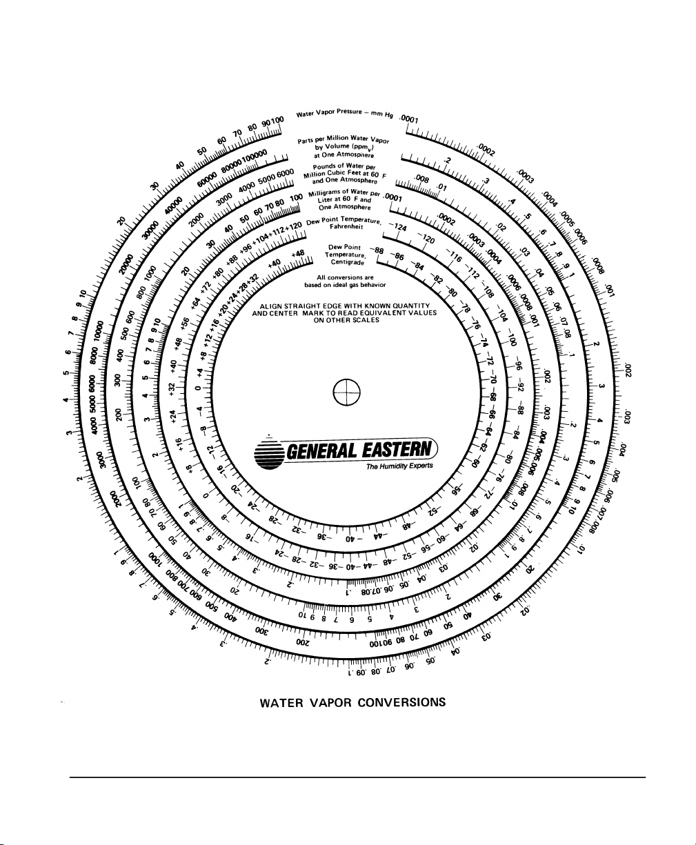
Figure 16 — Graphical Conversion Chart
Appendix D — Humidity Equations and Conversion Charts Page 71
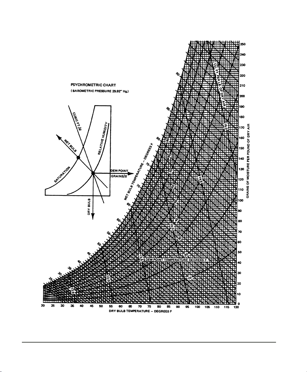
Figure 17 — Psychrometric Chart
Page 72 Appendix D — Humidity Equations and Conversion

Appendix E — Warranty information and
return procedures
Warranty policy
GE General Eastern warrants equipment of its manufacture against
defective materials or workmanship for a period of one year from
date of shipment. Liability of the Seller under this warranty is
limited, at the Seller’s option, to:
• Repair or replacement of defective parts at no charge.
• Credit adjustment, not to exceed original equipment sales
price.
This warranty is subject to the following conditions:
• Prompt notification to Seller upon discovery of defects or
missing items.
• Obtaining return authorization number from Seller to return
defective items to plant as directed.
• Return of equipment, freight charges prepaid, or as otherwise
agreed.
Defects caused by negligence, misuse, improper installation, accident or unauthorized repair or alteration by buyer or user, or any
modification, such as changing range resistors, may void this
warranty.
This warranty does not include mechanical parts failing from
normal usage nor does it cover limited life electrical components
which deteriorate with age.
This warranty is in lieu of all other warranties, expressed or
implied, including the implied warranty of fitness for a particular
purpose to the original purchaser or to any other person. Seller
shall not be liable for consequential damages of any kind.
Appendix E — Warranty information and return procedures Page 73

Damaged
shipments
In case of shipping damage, it is the Buyer’s responsibility to file a
claim. The customer should inspect the shipping container upon
receiving and note any evidence of damage on the freight receipt. If
concealed damage is found after opening the container, the
customer should file a claim with the carrier at once. The customer
must retain the shipping container and all materials.
Repaired
equipment
All repairs are warranted for 90 days. Only the repairs and components replaced as part of these repairs are covered by this warranty.
Other repairs or defective parts are covered by the original
warranty if applicable.
The aforementioned provisions are do not extend the original
warranty period of any article which has been either repaired or
replaced by the Seller.
Instrument return procedure
All GE General Eastern instruments are fully tested and calibrated
prior to shipment. Should a problem with the operation of the
equipment arise, follow the procedure below:
1. Contact the factory to discuss the problem. In countries other
than the U.S., the local agent can also be contacted. Sometimes a problem can be resolved by a change in operating procedure or an adjustment to the equipment.
2. If the equipment must be returned to the factory, obtain a
return authorization number from GE General Eastern, and
reference the number on the return shipping papers. A written description of the problem should also be included with
the instrument.
3. If equipment is not covered by GE General Eastern’s Warranty
Policy, a purchase order should be submitted with the equipment returned. The order should cover one of the following:
• Open order, authorizing repair of equipment to meet published specs. Repair costs will be billed on actual basis, but
will not exceed 50% of the replacement cost without prior
customer approval.
Page 74 Appendix E — Warranty information and return

• Order that is not to exceed $500.00 or 30% of the replacement cost, whichever is higher. If repair costs exceed this
amount, the customer will be quoted costs before the work is
done.
• Order to cover cost of test and evaluation only. Amount based
on type of equipment returned. GE General Eastern will evaluate but not repair the unit, and call the customer to discuss
the evaluation and quote the cost of repair or replacement.
GE General Eastern recommends the open order or the dollar- or
percentage-limited order. Either of these will expedite repairs and
reduce costs.
4. After receiving a Return Authorization number, the equipment must be returned freight PREPAID.
5. GE General Eastern reserves the right to apply a minimum
service charge in cases where an instrument is returned for
repairs or recalibration but does not require service.
Returning equipment without a Return Authorization number and
Purchase Order significantly delays turnaround time and incurs
additional costs. To expedite repairs and reduce costs, please follow
the above instructions.
GE General Eastern guarantees N.I.S.T. traceability and operation within stated specifications. However, claims regarding accuracy or traceability will be covered under warranty only when
verified at GE General Eastern, or by a fully independent testing
Iaboratory Examples of independent labs are: National Institute of
Standards and Technology in the U.S., the National Physical Laboratory (NPL) in the U.K.
Appendix E — Warranty information and return procedures Page 75

Page 76 Appendix E — Warranty information and return
 Loading...