

E4-1111H-GE
DEW POINT MONITOR
Operator’s Manual
The information in this manual is believed to be reliable.
However, General Eastern makes no warranty, expressed or implied, as to its accuracy and assumes no
liability arising out of its use by others. We reserve the
right to change this manual without prior notice.
Document No. A40232856/A00 ECO #5521
October 31, 2001 Printed in U.S.A.
Copyright
2001 General Eastern Instruments
The Humidity Experts
General Eastern Instruments
20 Commerce Way, Woburn, MA 01801-1057
Tel: (781) 938-7070 Fax: (781) 938-1071
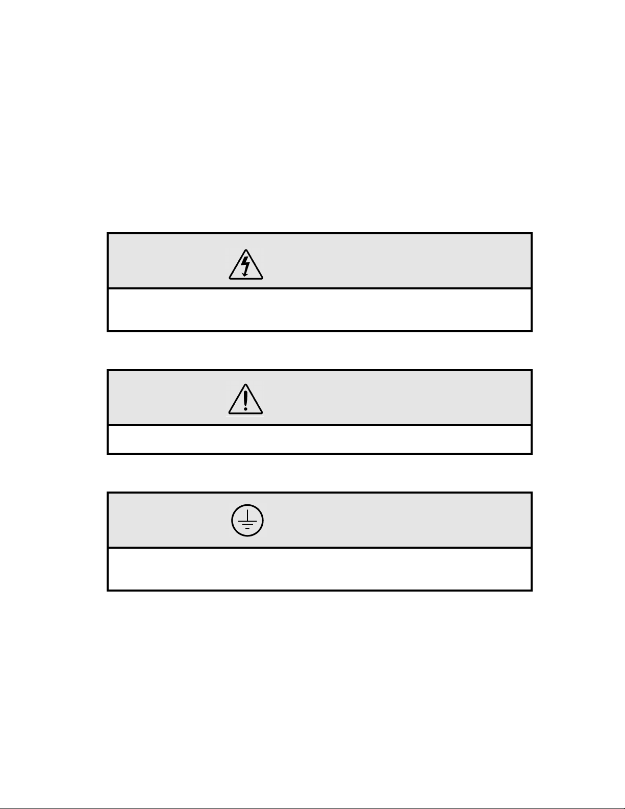
Safety:
This manual as well as safety labels posted on the instrument use the
following safety alerts to draw your attention to special safety instructions
that should be followed.
CAUTION
CAUTION: Hazards or unsafe practices could result in electrical shock, minor
injury, or product damage.
WARNING
WARNING: Refer to accompanying document for additional information.
ALERT:
ALERT
Earth ground connection; removal could result in electrical shock,
minor injury, or product malfunction.

CONTENTS
CHAPTER 1 — INTRODUCTION
About General Eastern - - - - - - - - - - - - - - - - - - - - - - 1
Overview of the E4-1111H-GE - - - - - - - - - - - - - - - - - - 1
The humidity sensor - - - - - - - - - - - - - - - - - - - - - - - 3
Theory of operation - - - - - - - - - - - - - - - - - - - - - - - - 3
CHAPTER 2 — INSTALLATION
Mounting - - - - - - - - - - - - - - - - - - - - - - - - - - - - - 7
Input power - - - - - - - - - - - - - - - - - - - - - - - - - - - - 8
Wiring the outputs - - - - - - - - - - - - - - - - - - - - - - - - 9
Sensor information - - - - - - - - - - - - - - - - - - - - - - - 12
Sensor replacement - - - - - - - - - - - - - - - - - - - - - - - 13
CHAPTER 3 — OPERATION
General information - - - - - - - - - - - - - - - - - - - - - - - 15
Control switches - - - - - - - - - - - - - - - - - - - - - - - - 15
RS-232C data outputs - - - - - - - - - - - - - - - - - - - - - - 17
Helpful hints for operating the unit - - - - - - - - - - - - - - - 17
The PACER Cycle - - - - - - - - - - - - - - - - - - - - - - - - 21
CHAPTER 4 — PROGRAMMING
General information - - - - - - - - - - - - - - - - - - - - - - - 23
RS-232C programming - - - - - - - - - - - - - - - - - - - - - 23
CHAPTER 5 — SERVICE
Minor maintenance of sensor optics - - - - - - - - - - - - - - - 31
Field replacement of sensor mirror - - - - - - - - - - - - - - - 32
Test and calibration - - - - - - - - - - - - - - - - - - - - - - - 35
Troubleshooting - - - - - - - - - - - - - - - - - - - - - - - - - 35
- - - - - - - - - - - - - - - - - - - - - - - 31
- - - - - - - - - - - - - - - - - - - - 1
- - - - - - - - - - - - - - - - - - - - 7
- - - - - - - - - - - - - - - - - - - - - 15
- - - - - - - - - - - - - - - - - - - 23
APPENDIX A — SPECIFICATIONS
APPENDIX B — WARRANTY AND RETURN PROCEDURE
- - - - - - - - - - - - - - - - - - 39
- - - - - - 41
APPENDIX C — HUMIDITY EQUATIONS AND CONVERSION CHART
APPENDIX D — CONFIGURING THE RS-232 INTERFACE
APPENDIX E — GLOSSARY
- - - - - - - - - - - - - - - - - - - - - 53
- - - - - - 49
45

FIGURES
Figure 1 Dimensions
Figure 2 The chilled-mirror hygrometer
Figure 3 Front view
Figure 4 Side view
Figure 5 Rear view
Figure 6 PC Board
Figure 7 Wiring and sensor replacement
Figure 8 DIP Switches
Figure 9 The PACER cycle
Figure 10 Results of the PACER cycle
Figure 11 Scaling parameters
Figure 12 Balance adjustment screw locations
Figure 13 Using a Resistance Decade Box
- - - - - - - - - - - - - - - - - - - - - - - 3
- - - - - - - - - - - - - - 4
- - - - - - - - - - - - - - - - - - - - - - - 7
- - - - - - - - - - - - - - - - - - - - - - - - 8
- - - - - - - - - - - - - - - - - - - - - - - - 9
- - - - - - - - - - - - - - - - - - - - - - - 10
- - - - - - - - - - - - - 11
- - - - - - - - - - - - - - - - - - - - - 16
- - - - - - - - - - - - - - - - - - - 21
- - - - - - - - - - - - - - - 22
- - - - - - - - - - - - - - - - - - - 25
- - - - - - - - - - - - - 37
- - - - - - - - - - - 32

Chapter 1 — Introduction
About General Eastern
General Eastern is devoted solely to the design and manufacturing
of accurate, reliable and rugged humidity measuring equipment.
We specialize in providing solutions for applications where
humidity measurements are critical.
There are many ways to make humidity measurements, and no one
humidity sensor meets all requirements for all applications. Our
variety of sensor types — including chilled mirror, lithium chloride,
resistance polymer, and wet bulb — can precisely determine dew
point, parts per million by volume, percent relative humidity, and
other parameters.
In keeping with General Eastern’s philosophy of providing the best
solutions to humidity measurement problems, we offer the
following products and services:
• high quality state-of-the-art instrumentation to assure excellent performance
• a broad range of humidity instruments capable of covering virtually any humidity measurement application
• full applications assistance to help you choose the sensor that
is best for your needs
• full and superior service, should it ever be needed
If you have questions about a particular measurement problem, we
invite you to call and discuss your application with one of our engineers. Call 800-225-3208 (if you’re calling from Massachusetts or
outside the United States, call 781-938-7070). Our fax number is
781-938-1071.
Overview of the E4-1111H-GE
The General Eastern E4-1111H is a multi-purpose chilled-mirror
hygrometer, suitable for use in a variety of applications. The unit
measures dew/frost point from –25°C to +65°C (–13°F to +149°F).
Chapter 1 — Introduction
1

The E4-1111H is designed for wall or surface mounting. It is
housed in a gasketed NEMA-4 aluminum enclosure, suitable for
industrial environments.
A 4–20mA analog output is provided as well as an RS-232C
communications port.
A red indicator light shows when
indicator light shows that the unit’s
tion (see “The PACER Cycle” beginning on page 21).
The monitor utilizes advanced microprocessor control and includes
General Eastern’s patented Programmable Automatic Contaminant
Error Reduction (PACER) system to insure accuracy.
Detailed specifications are given in Appendix A, beginning on
page 39.
POWER
BALANCE
is applied and a green
function is in opera-
System
Components
Physical
description
The complete system is packaged with the following items:
• The electronic monitor with integrated dew point sensor and
filter
• Operator’s manual
• Certification that the unit is traceable to the National Institute
of Standards and Technology
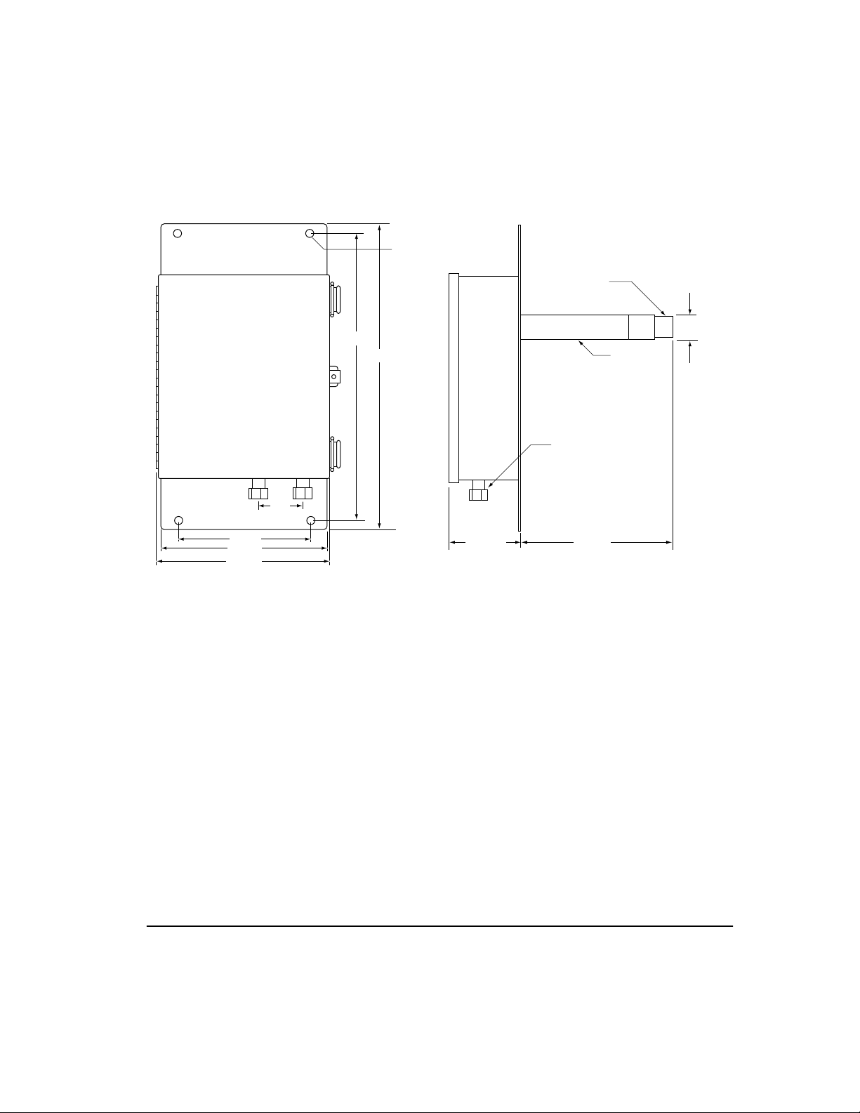
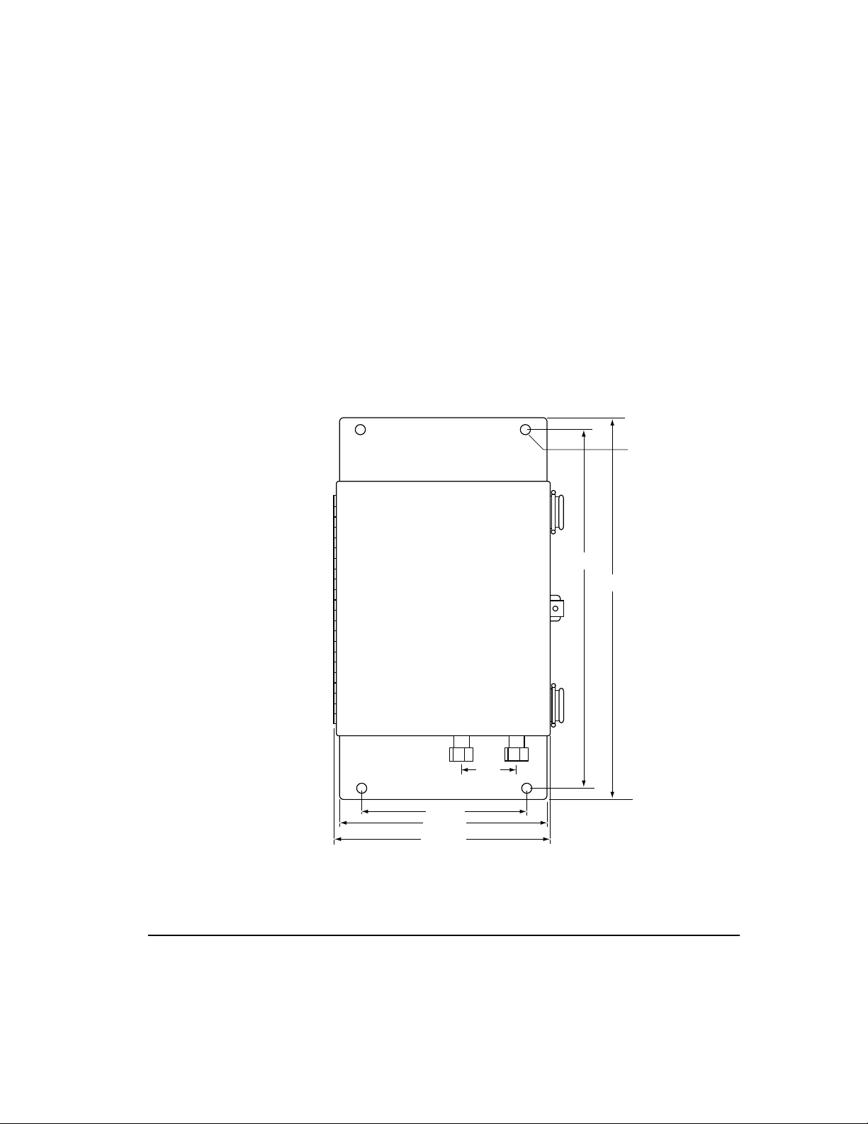
The E4-1111H is designed for surface mounting on a vertical wall
or panel. The unit’s dimensions are shown in Figure 1 in inches
(cm).
2
E4-1111H-GE Operator’s Manual
)
n
Ø 0.50 (12.7
4 plcs
3
Removable filter
17.36 (44.1)
2.75
(70)
8 (20.3)
10 (254)
10.5 (267)
The humidity sensor
The monitor is configured with a General Eastern 1111H
single-stage chilled-mirror dew point sensor. The sensor provides
data to the electronics unit that calculates humidity.
18.4 (468)
dimensions in
inches (mm)
4.25 (108)
Sensor Probe
1/2" Conduit fittings
Figure 1 — Dimensions
9.2 (237)
Figure 1 — Dimensions
1.5 (39)
dimensions i
inches (mm)
Theory of operation
What is Optical
Condensation
Hygrometry?
Chapter 1 — Introduction
Optical condensation hygrometry is a precise technique for determining the water vapor content in gases by directly measuring dew
point or frost temperatures. Using this technique, a metallic mirror
is cooled until it reaches a temperature at which a thin layer of
condensation begins to form on it. The dew layer is detected optically, and the mirror is held at that temperature. The mirror
temperature, measured with a platinum resistance thermometer, is
r
an accurate indicator of the dew or frost point. Because these
hygrometers are so accurate, they are widely used as a standard in
many of the world’s metrology laboratories.
How do General
Eastern
hygrometers
function?
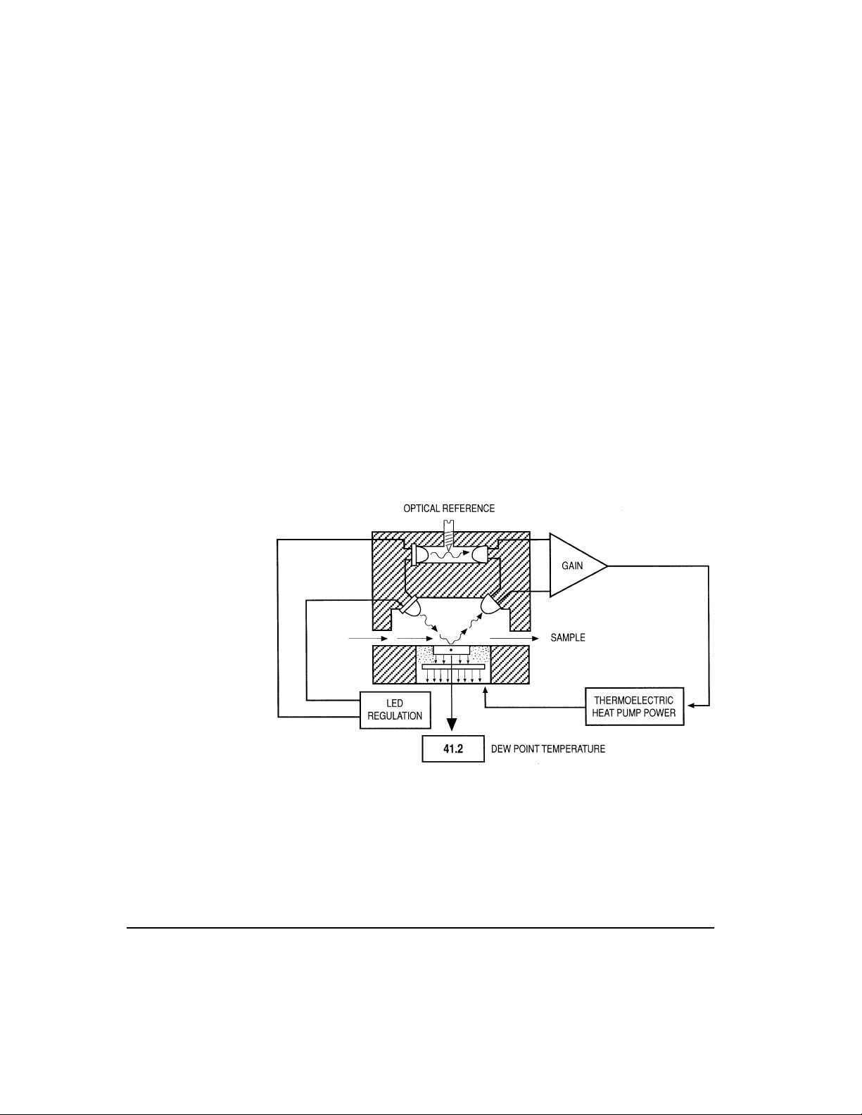
Figure 2 illustrates how General Eastern hygrometers detect and
measure dew point. The condensate mirror is illuminated with a
high-intensity, solid state, light emitting diode (LED). A photodetector monitors the LED light reflected from the mirror. The photodetector is fully illuminated when the mirror is clear of dew, and it
receives less light as dew forms. A separate LED and photodetector
pair are used as a known reference to compensate for any thermally
induced changes in the optical components. The photodetectors
are arranged in an electrical bridge circuit, the output current of
which is proportional to the light reflected from the mirror. The
bridge output controls the electrical current to the thermoelectric
cooler.
Figure 2 — The chilled-mirror hygromete
A large bridge current develops when the mirror is dry, causing the
mirror to cool toward the dew point. As dew begins to form on the
mirror, less light is reflected, and the bridge output decreases. This,
in turn, causes a decrease in cooling current. A rate feedback loop
4
E4-1111H-GE Operator’s Manual

5
within the amplifier ensures critical response, causing the mirror to
stabilize quickly at a temperature that maintains a thin dew or frost
layer on the mirror surface. A precision thermometer element
embedded within the mirror directly monitors this dew point
temperature.
Using General
Eastern
Hygrometers as a
standard for
calibration
An optical condensation hygrometer such as the E4-1111H can be
sent to the National Institute of Standards and Technology (NIST)
in Gaithersburg, Maryland for calibration against the NIST standard. A calibrated instrument can then be used as a transfer standard in local laboratories to calibrate lower echelon instruments.
Hygrometers used as calibration standards must have the following
characteristics:
• The mirror thermometer must have suitable long-term accuracy (such as that obtained with a platinum resistance thermometer).
• A means must be provided for viewing the dew or frost formation on the mirror.
Chapter 1 — Introduction

6
E4-1111H-GE Operator’s Manual
Mounting
)
Chapter 2 — Installation
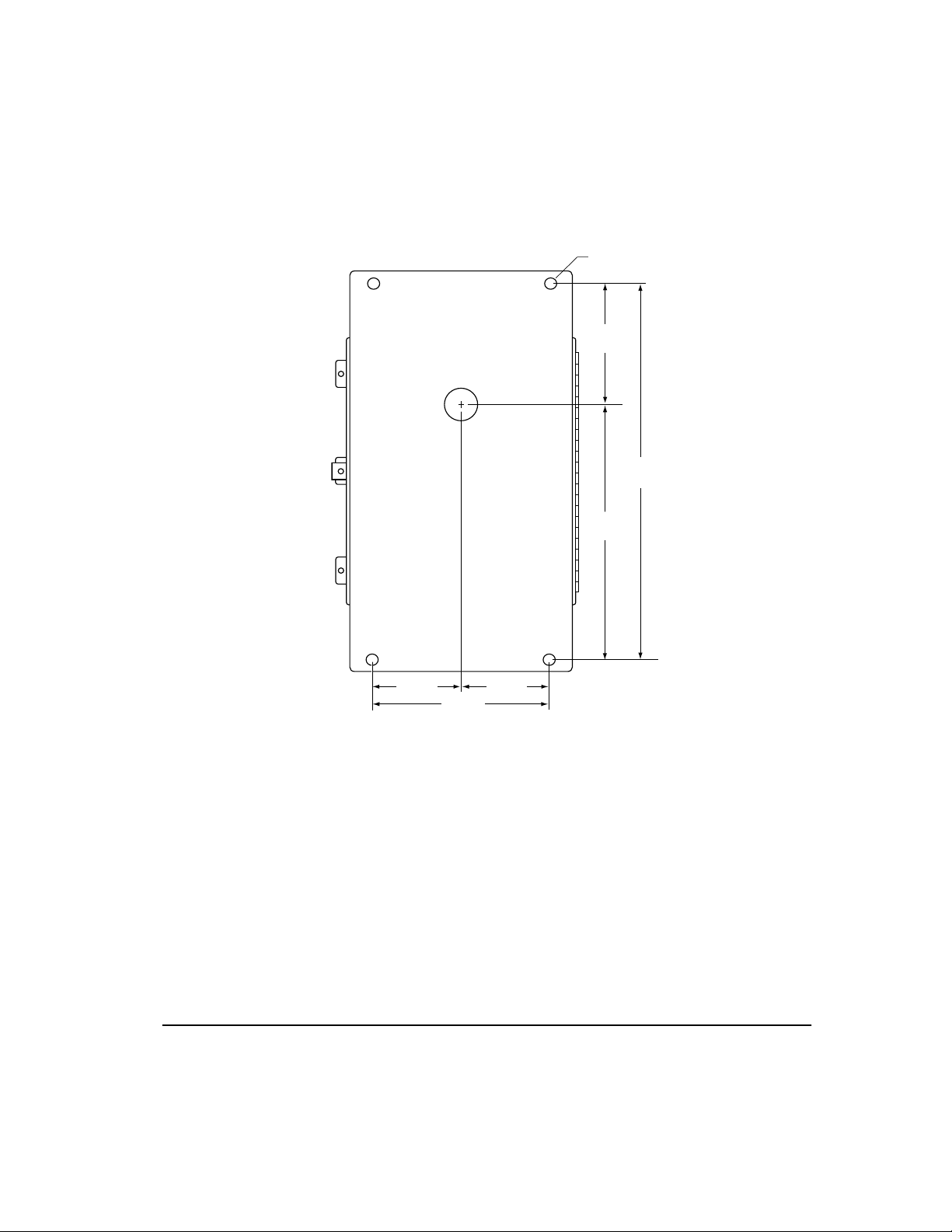
Mount the E4-1111H on a vertical surface using the four mounting
holes at the corners of the unit. Provide adequate space below the
unit for cabling, and to the left of the unit to allow the door to open
fully. The sensor module protrudes from the rear of the unit into
the measurement space. Mounting dimensions are shown in
Figures 3, 4 and 5.
Ø 0.50 (12.7
4 plcs
17.36 (44.1)
18.4 (468)
dimensions in
inches (mm)
Figure 3 — Front view
8 (20.3)
10 (254)
10.5 (267)
2.75
(70)
Chapter 2 — Installation
7
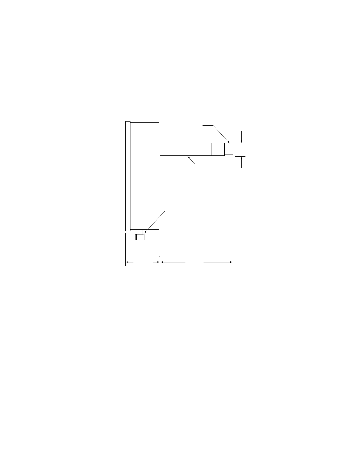
n
Removable filter
Sensor Probe
1.5 (39)
Input power
1/2" Conduit fittings
dimensions i
inches (mm)
4.25 (108)
9.2 (237)
Figure 4 — Side view
The E4-1111H is available in versions wired for 115, 230, and 100
VAC. The 230 VAC version is double-fused.
The unit’s voltage and frequency rating and tolerances, as well as
fusing data, are listed inside the unit.
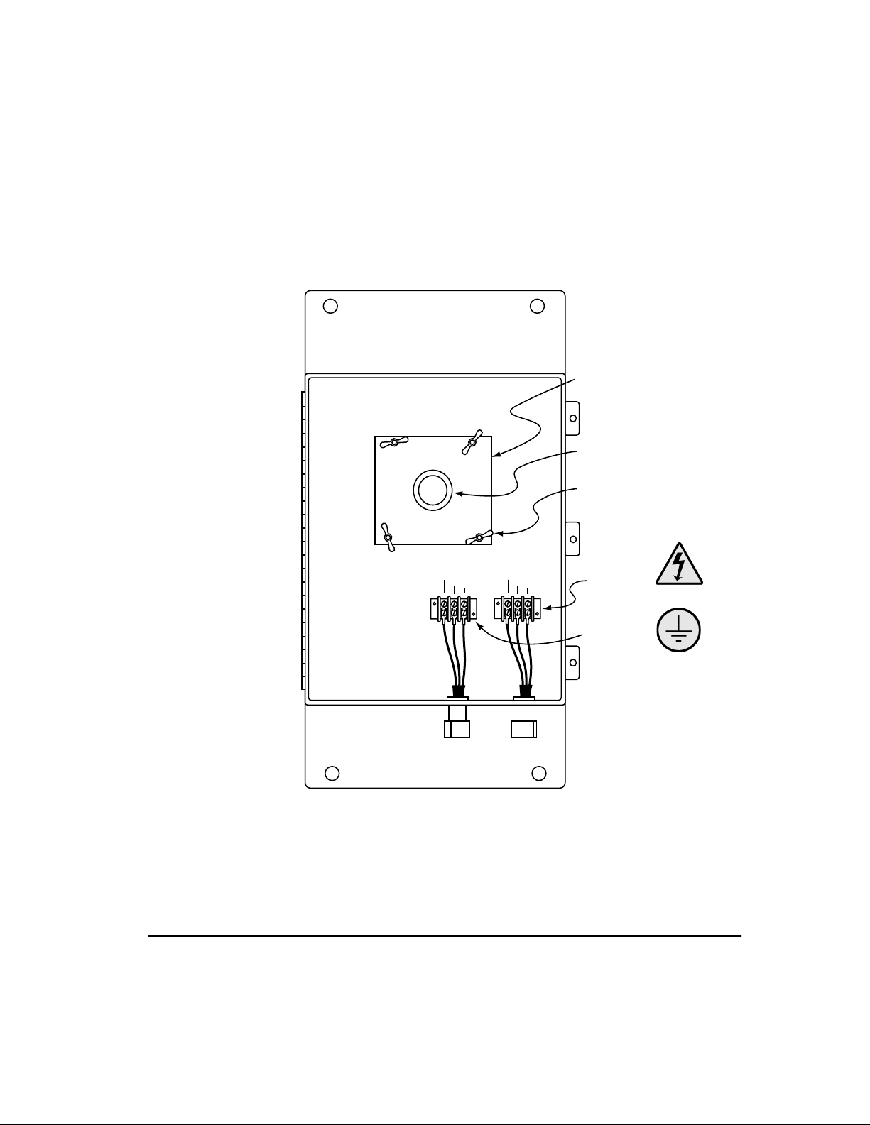
Input power wiring enters through the bottom edge of the unit and
connects to the right-hand terminal block as shown in Figure 7.
8
E4-1111H-GE Operator’s Manual
n
Ø
0.50 (12.7)
4 plcs
5.63
(143)
I+
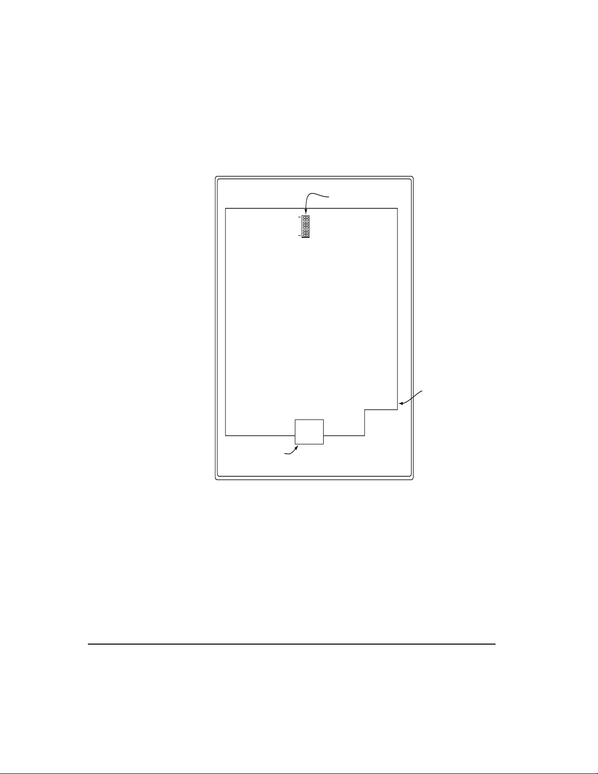
Wiring the outputs
The E4-1111H’s output terminals are located inside the unit’s front
door. Cabling is brought in through the bottom edge of the unit
and connected to terminal blocks as shown in Figure 7.
Analog humidity
output
The humidity output provides a 4–20mA analog signal (500 Ohms
maximum load). Connect to the terminals labelled
the left-hand terminal block.
4 (10.15)
8 (20.3)
4 (10.15)
11.73
(298)
17.36
(441)
dimensions i
inches (mm)
Figure 5 — Rear view
and
RTN
on
Chapter 2 — Installation
9
d
The humidity units and scaling may be set using the RS-232C port.
See “Chapter 4 — Programming” beginning on page 23 for details.
.
DIP switches
RS-232 Connector
Switch 1
Right Side (closed)Left Side (open)
Switch 8
PC Boar
Figure 6 — PC Board
Service output
10
The
SRVC
output provides a TTL-compatible signal that indicates
that the mirror needs cleaning (see page 31).
Connect to the terminals labelled
SRVC
and
Figure 7.
E4-1111H-GE Operator’s Manual
RTN
as shown in
RS-232C
connector
The RS-232C connector is located at the bottom edge of the PC
board (see Figure 6). It provides RS-232C digital communications
between the unit and an RS-232C terminal or a PC running in
terminal emulation mode.
Sensor mounting
plate
Sensor cable
connection
Wing nuts (4 plcs)
SRVC
RTN
L (line)
I+
Ground
N (neutral)
AC power
Chapter 2 — Installation
Outputs
Figure 7 — Wiring and sensor replacement
The connector is a standard 25-pin D connector. For connection to
another RS-232C device, the cable is wired as shown below. Pin
connections are given for both 25-pin and 9-pin devices.
11

E4-1111H
25-pin device 9-pin device
232
323
775
The baud rate of the data is 1200. The format of the data is 8 data
bits, 1 stop bit, and no parity.
The unit can communicate with a handheld RS-232C terminal or a
personal computer running in terminal emulation mode. See
Appendix D for a BASIC computer program that can be used for
simple RS-232C communications between the unit and your PC.
Handshaking.
to
NO HANDSHAKE
In order to enable handshaking, the RS-232C menu must be
accessed through the RS-232C port. See “Handshake control” on
page 28 for details. To implement handshake control using
Clear-To-Send and Ready-To-Send, use pins 4 and 5. Applying 8
volts (
transmit.
3) to Pin 5 of the RS-232C connector allows the unit to
±
The default handshaking protocol for the unit is set
.
Sensor information
Filter
Requirements
Flow Rate
12
The E4-1111H is equipped with a submicron Teflon filter to avoid
particulate contamination and to protect the sensor from the presence of liquid water. In many applications, the filter requires periodic inspection and replacement. Typical applications might
require replacement twice a year.
It is important to have adequate flow through the sensor. Too little
flow can slow the response (particularly at very low frost points).
E4-1111H-GE Operator’s Manual

Too much flow can cause instability of the control system at high
dew points and can reduce the depression capability of the cooling
pump at very low dew points. Too much flow also accelerates the
rate of system contamination. A flow rate of 2 to 2.5 ft
over 1 liter/min) is ideal for most applications. In many cases, flow
rates between 0.2 and 5 ft
Sensor replacement
If it necessary to remove the sensor module, follow the steps below:
1. Disconnect the line power from the unit.
2. Open the front door.
3. Unplug the sensor cable from the end of the sensor probe as
shown in Figure 7.
4. Unscrew the four wing nuts shown in Figure 7.
5. Carefully remove the sensor module.
3
/h (a little
3
/h (0.1 and 2.5 liter/min) may be used.
13
Chapter 2 — Installation

14
E4-1111H-GE Operator’s Manual

Chapter 3 — Operation
General information
Operating instructions fall into three categories:
• normal operation
• setup and programming
• system maintenance
Normal operation of the unit’s controls is described in the next
section.
Setup and programming involves customizing the unit for specialized applications, and is not required for many conventional applications. The unit is shipped properly programmed to meet the
customer’s requirements (see Appendix A). Complete programming
instructions are given in Chapter 4, beginning on page 23.
Maintenance involves manually testing the unit’s cooling capacity,
clearing the mirror, and other operations that might be required on
a regular basis, or when a problem is suspected, depending on the
application.
An RS-232C-compatible device, such as a laptop computer, can be
connected to the unit to perform programming and configuration
functions. The RS-232C port can also be used to send data
measured by the unit to an external computer or other device.
Control switches
Control switches are located at the top edge of the PC board,
within the red switch module containing eight DIP switches.
Switches are number from 1 to 8, with Switch 1 at the top and
Switch 8 at the bottom as shown in Figure 8.
Chapter 3 — Operation 15

)
s
Switch 1
Switch 2
Switch 3
Left Side
(contacts open)
Switch 4
Switch 5
Switch 6
Switch 7
Switch 8
Right Side
(contacts closed
Figure 8 — DIP Switche
All switches are normally set to the open position, with the
left-hand side depressed. Press the right hand side to activate a
function as described below. (Switches 5–8 are not used).
Switch Function Left side pressed Right side pressed
1 Mirror cooling Normal Cool the mirror.
2 Mirror heating Normal Heat the mirror.
3 Initiate PACER
cycle
4 Automatic
Normal Initiate one PACER
cycle.
Normal Periodic PACER cycles.
PACER cycles
The PACER cycle for automatically cleaning the sensor mirror is
described in “The PACER Cycle” beginning on page 21.
To initiate a single PACER cycle, press Switch 3 to the right and
then return it to the normal position.
To cause automatic PACER cycles at a programmable periodic rate,
set Switch 4 to the right. See “Setting the balance interval.” beginning
on page 26 for programming the rate.
16 E4-1111H-GE Operator’s Manual

RS-232C data outputs
See “RS-232C connector” on page 11 for details on hardware,
cabling and protocols for establishing RS-232 communications with
the monitor. RS-232 communications can be divided into two
sections: Operate Mode and Programming Mode.
Operate Mode
While the unit is in Operate Mode, the RS-232C port can provide
any data that is available. The data available for this model is as
follows:
DP C=xxxx
DP F=xxxx
The data output by the unit can be modified in two ways:
• the user can customize the data output to a subset of the
above (See “RS-232C programming” on page 23.)
• the user can enter commands via the RS-232C port to obtain
immediate output of a single parameter (See “Outputting data
‘on command’” on page 28.)
Programming is described in “Chapter 4 — Programming” beginning
on page 23.
Helpful hints for operating the unit
Time response
At dew points above 0°C, the system stabilizes within a few seconds
at a consistent dew or frost layer. Once the system is stable valid
readings may be taken.
When the system is operating at very low frost points (below
–40°C), extra care may be required when interpreting readings
because of the slower response of the system. Time response
depends on a number of factors including dew/frost point, slew
rate, upstream filtering, and flow rate.
• As the dew/frost point becomes lower, water molecules in the
air sample become scarcer, and it takes longer to condense a
frost layer on the mirror sufficiently thick to establish an equilibrium condition.
Chapter 3 — Operation 17

• Temperature slew rate is dependent on dew point and depression (the temperature difference between the mirror and the
sensor body); at higher dew points and moderate depressions,
it is typically 1.5°C/second. At lower dew points and/or larger
depressions, slew rate becomes progressively slower.
• Flow rate affects response by determining the rate at which
water vapor is supplied or carried off.
There is, of course, a trade-off between response time, control
system stability, and sensitivity to contamination.
Supercooled dew
points
Contamination
Slightly below the freezing point, water can exist in a supercooled
liquid state for extended periods of time. Extra care may be needed
when making measurements in the frost point region of 0 to –20°C,
because the mirror temperature may temporarily stabilize at the
supercooled dew point, 0.5 to 1°C below the actual frost point.
To assure that the unit is operating in the ice phase within this
temperature range, allow the instrument to operate continuously.
Before manually clearing a frost layer, take a reading, and afterwards allow sufficient time to reform a stable frost layer before
taking further readings.
Mirror Cleanliness. Proper operation of a condensation hygrometer
depends on the condition of the mirror surface. In general, accuracy
is reduced when contaminants accumulate on the mirror.
However, the mirror does not have to be microscopically clean. In
fact, the mirror performs best a few hours after cleaning, when
nucleation sites have formed. On an unscratched, freshly cleaned
mirror, there are relatively few nucleation sites on which dew or
frost deposits can form, and more time is required to collect a
condensation layer at low frost points. Also, overshoot may occur,
which can cause oscillations as the temperature stabilizes.
Particulate contaminants.
water may accumulate on the mirror surface, but does not affect
the instrument accuracy until the mirror reflectance is reduced
substantially. In many cases, particulates improve instrument
response by providing condensation sites.
Particulate matter that is insoluble in
18 E4-1111H-GE Operator’s Manual

Water-soluble contaminants.
Contaminants which readily
dissolve in water, such as naturally occurring salts, are detrimental
to accurate vapor concentration measurement by any condensation method. These materials readily go into solution with the
water condensate on the mirror surface, and then reduce the vapor
pressure in accordance with Raoult’s Law. As the concentration
increases with time, the saturation vapor pressure of the liquid
solution decreases.
The unit responds to this lower vapor pressure by elevating the
mirror temperature in order to maintain a vapor pressure that is in
equilibrium with the partial pressure of atmospheric water vapor.
The measured dew point, therefore, drifts upward above the true
dew point. Because the measurement error increases gradually, it
often goes undetected.
To determine whether dissolved contaminants are affecting dew
point measurement, perform the following steps:
1. Note the indicated dew point
2. Clean the mirror
3. Balance the detector by initiating a PACER cycle
4. Measure the dew point again
If the new reading is lower than the first reading, it is likely that
soluble material was present in sufficient quantity to cause a
measurement error.
Gaseous contaminants.
When a gaseous material that has a higher
condensation temperature than that of water is present (even in
very low concentrations), the unit will eventually control on that
material, rather than on water. The system then displays the
condensation temperature of the contaminant, not of water. Such
material accumulates on the mirror only when chilled. In the
normal atmosphere, gaseous contaminants do not have a detectable effect.
Minimizing the effects of contaminants.
1. Use the PACER feature to reduce the effect of contaminants on
the unit’s performance.
2. Reduce the gas flow rate to reduce the rate of accumulation of
contaminants on the mirror.
Chapter 3 — Operation 19

3. Clean the mirror according to the recommended optics clean-
ing procedure. See “Cleaning the sensor mirror” on page 31. To
determine the proper cleaning interval for a given set of conditions, take a dew point reading before and after the cleaning.
Any appreciable shift indicates that under these conditions,
the mirror should be cleaned more often.
Mirror Flooding
Sample line
maintenance
Pressure effects
If there is an abrupt transition from dry to moist conditions (particularly when accompanied by a transition from cold to warm
temperatures), the mirror may accumulate an overload of moisture.
It then may take several minutes before the sensor dries out and
valid readings can be obtained. The drying process can be accelerated by setting DIP Switch 2 to
sensor.
Contaminated sample lines slow the unit’s response time and can
cause erroneous readings, usually on the high side. Clean the
sample lines as often as necessary. To determine the required
cleaning frequency, take dew point readings before and after
cleaning the lines, sensor cavity, and mirror. If the two readings
differ appreciably, the sampling lines should be cleaned more often.
To reduce the rate of contamination, reduce flow and/or install a
filter upstream.
If the pressure of the gas is increased or reduced from atmospheric
pressure, but the mixing ratio (moisture content) stays constant,
the dew point is correspondingly increased or decreased. The
monitor displays the dew/frost point at the pressure to which the
sensor chamber is exposed. The sensor location and hookup
arrangement can influence the pressure. The dew point change due
to pressure change can be calculated by using Dalton’s Law and the
Smithsonian Tables or a proper nomograph. Appendix C contains
basic data for these calculations. Request a copy of General
Eastern’s Humidity Handbook for additional detailed information.
HEAT, to temporarily heat the
20 E4-1111H-GE Operator’s Manual

The PACER Cycle
General Eastern has developed and patented a compensation technique called PACER (Programmable Automatic Contaminant Error
Reduction) that is very effective in reducing the Raoult Effect error
associated with soluble contaminants, particularly for near-ambient
dew points. The PACER cycle replaces the AUTO balance cycle
available on earlier General Eastern products.
Figure 9 — The PACER cycle
The PACER cycle, diagrammed in Figure 9, begins with a coalescence period, during which the mirror is cooled well below the dew
point of the sample gas, condensing out a large amount of water.
This excess water easily dissolves any water-soluble contaminants.
The mirror is then heated. During the heating phase, the large
puddles of water gradually evaporate, carrying increasingly heavy
concentrations of salt as the puddles become smaller. Finally, when
all the puddles have evaporated, dry “islands” of crystallized salt
are left on the mirror. The area between the islands (80-85% of the
mirror surface) is now clean and shiny, whereas before the PACER
cycle it may have been completely covered. The total amount of
contamination has not been reduced, but instead redistributed as
Chapter 3 — Operation 21

shown in Figure 10, with more clean mirror surface available for
dew formation.
Before
Pacer Cycle
After
Pacer Cycle
Figure 10 — Results of the PACER cycle
22 E4-1111H-GE Operator’s Manual

Chapter 4 — Programming
General information
The E4-1111H-GE is programmed at the factory to display and
output the data required for most applications. In many cases, no
further programming is required.
Programming allows control of two major items:
• the analog outputs
• the digital (RS-232C) outputs
Programming is most easily accomplished using a computer or data
terminal connected to the RS-232C data port.
Note that commands issued to the unit through the RS-232C port
would usually come from a manually operated computer or terminal
as described below. For specialized automated operation, commands
could also be issued autonomously by a properly programmed computer.
RS-232C programming
Programming of the unit using the RS-232C channel is accomplished by a series of menus described in this section. The menus
can be accessed by a computer or data terminal connected to the
unit’s RS-232C data port. The Data Terminal Emulator included in
Windows software provides a very convenient means of controlling
the unit.
The programming menus are not available while BALANCE mode is
active. (Switch 3 in closed position)
When programming menus are active, the sensor cooling is deactivated and the sensor mirror is allowed to rise to ambient temperature.
Chapter 4 — Programming 23

Main menu
(software
version 2.0)
The main menu is the starting point for all programming functions.
To access the main menu from normal operating mode, press ESC
(hex 1B) twice on your terminal. To return to the main menu from
any sub-menu, press E on your terminal one or more times until
the main menu is displayed. The main menu will contain some or
all of the following choices, depending on the model:
1) Scale Outputs 2) Set Balance Type 3) Set RS-232 Units
4) Display Option 5) Set Averaging 6) Calibrate Output1
E) Exit
Press the digit or letter corresponding to the item you wish to
program.
When finished, press E from the main menu to return to OPERATE
mode. Note that several seconds may be required for the system to
respond and provide data on the RS-232 terminal or the main
display.
Each menu item is described in detail in the sections following.
Function 1:
Scale outputs
From the main menu, press 1 to assign and scale the analog
outputs. The current output selection(s) and scaling are displayed,
followed by the Scale Outputs menu:
OUTPUT1:
DP C:
HIGH = 75 LOW = -45
1) OUTPUT1 E) EXIT
Scaling Output1. Press 1 to access the Output1 menu, which
controls the Humidity output. The text OUTPUT1: is displayed,
followed by the menu listed below:
OUTPUT1:
0) DPC 1) DPF E) EXIT
24 E4-1111H-GE Operator’s Manual

Select a humidity parameter to be output, or press E to exit and
return to the previous menu. If you select a parameter, the unit will
also ask for the analog output scaling values (full-scale high and
low values for the analog outputs).
HIGH =
Enter the value that should cause full-scale output (20mA), and
press RETURN.
LOW =
Enter the value that should cause 4mA output, and press RETURN.
The unit will again display the newly entered values and the Scale
Outputs
menu. Check the values, and press E to exit back to the
main menu. When the unit returns to operating mode, the analog
output voltage will vary with the measured humidity as shown in
Figure 11.
Analog
output
20mA
4mA
Humidity
Low High
Figure 11 — Scaling parameters
Function 2:
Set balance type
Chapter 4 — Programming 25
From the main menu, press 2 to change the type of balance used,
to adjust the balance interval, or to remotely initiate a balance

cycle. The current balance state is displayed, followed by the
Balance Type menu.
BALANCE TYPE = Pacer
DAY = 0
HOUR = 12
1) Pacer Bal 2) Auto Bal 3) Set Interval
4) Initiate Balance E) Exit
Selecting the balance type. Press 1 to set the type of balance to
PACER (the default) or 2 to set the type of balance to AUTO.
Note: In the E4-1111H, only the PACER cycle type is available, even
though the older AUTO cycle can be selected. Do not use the AUTO
setting. See “The PACER Cycle” on page 21.
Setting the balance interval. To set the balance interval, press 3.
The balance interval is specified in days and hours, and the interval
will be the sum of the days and the hours entered. The following
will appear:
DAY =
Type a value for the number of complete days between balance
cycles and press RETURN. The following will appear:
HOUR =
Type a value from 1 to 24 for the number of hours between
balance cycles, and press RETURN.
The new interval will be displayed, and the unit will return to the
Balance Type menu.
26 E4-1111H-GE Operator’s Manual

Examples:
Day = 0 Balance every 12 hours
Hour = 12
Function 3:
Set RS-232 Units
Day = 1
Hour = 0
Day = 5
Hour = 12
Balance every 24 hours
Balance every 5½ days
Initiating a single balance cycle. Press 4 to manually initiate a
balance cycle. The unit will return to normal operating mode at the
completion of the cycle.
Press E to return to the main menu.
From the main menu, press 3 to customize the RS-232C data
output. This menu selects the units to be output and the handshaking status. The currently selected units and handshaking
status are displayed, followed by the Set RS-232 Units menu.
Selected Units = 1,2
Handshake = Disabled
1) Data 2) Handshake (Toggle) 3) Exit
Selecting output data. Press 1 to configure the RS-232C data
output units. The following menu is displayed:
1) Select Units 2) User Prompt E) Exit
Press 1 to select the parameters to be displayed. The following
menu is displayed:
1) DPC 2) DPF 3) None E) Exit
Press numbers individually to add the designated parameter to the
RS-232C data output. Press the digit for “None” to turn off all data
outputs, or to clear the list before adding parameters.
Chapter 4 — Programming 27

Outputting data ‘on command’. A feature of the E4-1111H allows
the unit to output data only when commanded or “prompted” by
the user or by an external device. When a command code is
received by the unit while operating in this mode, the data associated with that code will be output.
To configure the unit to output data on command, press 2 from the
above menu to select User Prompt. The current user-prompt
status is displayed, and a sub-menu allows the status to be
changed.
Status = Disabled
ALLOW USER TO PROMPT FOR DATA
1) Enable 2) Disable E) Exit
Press 1 to enable the user prompt for data. Press E twice to return
to OPERATE Mode. To return to normal operation, access the above
menu and press 2 to disable this function.
While the unit is set to output data ‘on command,’ data will be
output only when requested by the user prompt.
To output dew point in °C, enter the prompt “D1”.
Handshake control. From the Set RS-232C units menu, press 2
to change the handshake protocol. The default is “no handshake.”
The unit will ask for a password before allowing the handshaking
protocol to be changed.
Enter Access Code:
Type the code word “ACCESS”. The status will be changed and the
new status will be displayed. Press E to return to the main menu.
Function 5:
Set Averaging
28 E4-1111H-GE Operator’s Manual
From the main menu, press 5 to set the data averaging parameter.
This number determines how many dew point readings are averaged to determine the reading that is output. The number may

range between 1 and 20. The factory default is 20. The current
value is displayed, followed by a menu:
Number of Points = 20
1) Set Average E) Exit
Press 1 to change the number of points to be averaged. The current
averaging value is displayed:
VALUE =
Type a value between 1 and 20 and press RETURN. The new value
is displayed. Press E to Exit.
Function 6:
Calibrate
Output1
To calibrate the unit’s Output1 (humidity), the following equipment
is required:
•4½-digit voltmeter
• 0.01%, 100-Ohm precision resistor
CAUTION
Please consult the factory before attempting to calibrate
the outputs of the unit. All analog outputs are factory
calibrated and normally do not require calibration or
field adjustment.
From the main menu, press 6 to calibrate the HUMIDITY output.
The analog outputs are calibrated at the factory and normally
never require recalibration. To protect against inadvertent calibration, this function is protected by a password. The following is
displayed, allowing the password to be entered:
Enter Access Code:
Chapter 4 — Programming 29

Type the code “ACCESS”. The Calibrate Output1 menu is
displayed:
1) Calib Output 2) Check Output E) Exit
Calibrating the current output. Disconnect all devices from the
unit’s humidity output. Connect the 100-Ohm precision resistor
across I+ and RTN terminals. Connect the voltmeter across the
resistor leads. Set the voltmeter to 4 volts full scale.
From the above menu, press 1 to calibrate the humidity current
output. The unit passes a current through the resistor, generating a
voltage measured by the voltmeter. Multiply this voltage by 10 to
convert it to milliamps of current in the resistor, and enter the
result:
VALUE =
For example, if the voltmeter reads 1.6421 volts, type 16.421 and
press RETURN.
The unit passes a new current through the resistor, and asks for a
new reading to be entered. Type the new voltage (times 10) and
press RETURN. The unit recalibrates its HUMIDITY output and
returns to the Calibrate Output1 menu.
30 E4-1111H-GE Operator’s Manual

Chapter 5 — Service
Minor maintenance of sensor optics
Periodically inspect and maintain the sensor optics as described in
the following paragraphs.
Cleaning the
sensor mirror
Balancing the
sensor optics
Under normal conditions, the system is self-checking and
self-balancing. However, there are occasions when particulate
matter and water-soluble contaminants reduce sensor mirror
reflectance and system accuracy. See “Contamination” on page 18.
When necessary, clean the sensor mirror, following the procedure
below.
1. Deactivate the sensor cooler, by placing DIP Switch 2 to HEAT
(press the right-hand side).
2. Open the sensor by removing the sensor filter.
3. Moisten a cotton swab with a cleaning solution suitable for
mirrors, such as the blue cleaning solution in the General Eastern maintenance kit, or dilute methanol or alcohol. Clean the
mirror with a few light wipes. If the sensor has been exposed
to significant contamination, clean the other optical surfaces
in the sensor and the sensor cavity itself.
4. Replace the sensor filter.
5. Return switches to normal.
6. Initiate a PACER cycle by closing Switch 3 and then returning
it to the open position
If the service “SRVC” TTL output reappears after a PACER cycle
(even after performing the mirror cleaning procedure above) check
the sensor balance adjustment. Improper adjustment of the optical
balance is the most common cause of instrument malfunction. In
addition, new systems may require an optical balance adjustment
after one or two months of operation. Always clean the mirror as
described above before performing an optical balance.
Chapter 5 — Service 31

1. Clean the mirror as described in “Cleaning the sensor mirror”
on page 31, if you have not already done so.
2. Set DIP Switch 2 to HEAT (right-hand position) and wait one
minute for any condensation to evaporate.
Be sure to cover the optical cavity with your hand to prevent
ambient light from affecting the sensor balance.
3. Observe the green BALANCE LED at the bottom of the unit. If
the LED is illuminated, the sensor is properly balanced. If not,
balance the sensor using the following steps.
4. Turn the balance screw on the sensor COUNTERCLOCKWISE
until the BALANCE light goes out. The location of the balance
adjustment screw is shown in Figure 12.
5. Slowly turn the balance screw CLOCKWISE until the BALANCE
light just comes on.
6. Replace the sensor filter and verify that the BALANCE LED
remains illuminated.
7. Return DIP Switch 2 to the normal (left) position to stop heating the mirror.
8. Initiate a PACER cycle by switching DIP Switch 3 to the right,
and then returning it to the left.
Sensor balance
adjustment screw
(shown with filter
removed)
Figure 12 — Balance adjustment screw locations
At the completion of the PACER cycle, the system is properly
balanced. For more information on the PACER cycle, see “The
PACER Cycle” on page 21.
Field replacement of sensor mirror
One advantage of the General Eastern chilled mirror dew point
sensor is that the mirror is user-replaceable. The sensor does not
have to be returned to the factory for replacement of the reflective
32 E4-1111H-GE Operator’s Manual

surface, but of course you can return it for factory service, if
desired.
A mirror may require replacement for any of the following reasons:
• The mirror is constructed of silver/rhodium plated copper.
Copper provides excellent thermal conductivity to the platinum thermometer. However, some gas constituents, such as
sulfur dioxide (SO2) may react with the copper and eventually
pit the surface or form a copper sulfate coating.
• The reflective surface may be gradually abraded by sharp dirt
particles in the gas being measured.
• The mirror surface may be accidentally scratched or gouged
during use or cleaning.
If the sensor mirror has reacted with a corrosive material in the gas
sample, such as an acid or sulfur compound, it should be replaced
with a solid platinum mirror to remove any possibility of copper
corrosion.
In extreme cases, a solid platinum mirror can make possible a
successful application of chilled mirror technology. For example,
measurements in tobacco factories and malting houses have drastically improved after this change, since both locations have sample
gas constituents that attack copper.
In addition, fine scratches can be buffed out of a solid platinum
surface, restoring the mirror to new condition, since it is of solid
construction.
Replacing the
sensor mirror
Chapter 5 — Service 33
Required equipment: torque driver, set to 20-30 inch-ounces of
torque. General Eastern’s type TW-1 is recommended.
The kit supplied by the factory contains the replacement mirror, a
container of white thermal compound for proper heat transfer, and
(in some models) a mylar washer that is to be placed under the
mirror.
1. Open the sensor by removing the sensor filter.
2. Unscrew and discard the old mirror, using a 3/16-inch (0.187)
hex socket.

3. Use a toothpick or similar tool to place a small amount of thermal compound in the hole supporting the mirror.
CAUTIONS:
Do not apply thermal compound to the mirror stem.
Do not use an amount large enough to leak out when
the mirror is tightened.
Do not allow any compound to get on the mirror sur-
face, as it is very difficult to remove completely.
4. Carefully screw in the new mirror and tighten to the proper
torque as specified for the particular sensor.
5. Carefully clean the mirror surface, using a cotton swab and the
General Eastern cleaning solution supplied with the maintenance kit. Distilled alcohol or diluted alcohol is also acceptable.
6. Replace the filter and return the sensor to normal operation.
Under some circumstances, a new mirror may operate in a
somewhat unstable manner for the first hour or two.
Modification for platinum mirror. If you choose to upgrade from
the standard plated copper mirror to the solid platinum mirror in
the field, a circuit board change must also be made within the
E4-1111H. Capacitor C4 must be increased from 33 microfarads to
approximately 68 microfarads to avoid instability in the control
loop. This change can be accomplished either by replacing C4 with
a larger capacitor, or by adding a 33 microfarad capacitor in parallel
with C4 using the designated pads on the circuit board.
If you received a system that had a platinum mirror installed at the
factory, an additional 33 microfarad capacitor has already been
added in parallel with C4.
If you purchase a platinum mirror to replace a standard mirror, you
can return the unit to the factory for a no-charge circuit board
modification. If you prefer to install the modification, General
Eastern will supply a field modification kit at no charge. A trained
electronic technician with soldering skills is required for proper
circuit board modification.
34 E4-1111H-GE Operator’s Manual

Test and calibration
The procedures in this section effectively test and/or calibrate the
following aspects of the monitor:
• Startup and power supply voltage
• Normal sensor operation
• Digital and analog outputs
• No heating or cooling
The unit has been completely tested and calibrated at the factory,
and is ready to plug in and operate. As shipped, it meets all of our
published specifications and has been checked out at a number of
points against a dew point system that has been certified by the
U.S. National Institute of Standards and Technology (NIST). A certificate of Compliance is supplied with the unit to indicate traceability.
There are no calibration adjustments in the instrument that affect
the measured readings. The reading is determined directly from the
mirror temperature measured by the platinum Resistance Temperature Detector (RTD), which is controlled automatically at the dew
point.
The analog outputs provided for recording or controlling are
produced by a digital-to-analog converter. This converter can be
adjusted as specified in the analog output calibration procedures.
See “Function 6: Calibrate Output1” on page 29.
Troubleshooting
Red POWER
indicator doesn’t
light when
powered up
Incorrect dew
point measured
Chapter 5 — Service 35
1. Check the AC line supply. Make sure both ends are connected
and that the unit is connected to a proper source of AC voltage.
2. Check the fuse. Make sure the proper fuse size is installed.
Make sure the fuse is not open.
If the dew/frost point reads incorrectly, first check the standard
preventive maintenance items:

1. Clean the mirror. See “Cleaning the sensor mirror” on page 31.
2. Balance the sensor optics. See “Balancing the sensor optics” on
page 31.
If the above procedures do not correct the problem, verify that the
platinum resistance thermometer in the sensor is reading correctly
with the following steps:
1. Disconnect the 6-pin J9 connector from the main circuit board
in the unit. After J9 has been disconnected, and after the sensor mirror has stabilized at ambient temperature, the measured dew point should equal the ambient temperature.
2. Check this temperature reading against another reliable thermometer placed near the dew point sensor.
3. If the platinum resistance thermometer is faulty, return the
sensor to General Eastern for factory service.
An alternative method for checking the accuracy of the unit’s electronics is to use a precision resistance decade box in place of the
platinum thermometer. Wire the decade box to the unit’s sensor
connector as shown in Figure 13, and verify that the resistance
settings shown in the table produce the temperatures shown.
36 E4-1111H-GE Operator’s Manual

Figure 13 — Using a Resistance Decade Box
No analog output
No digital
RS-232C output
Chapter 5 — Service 37
If there is no analog output, check the analog output scaling. See
“Function 1: Scale outputs” on page 24.
Check the output scaling for the RS-232C port. See “Function 1:
Scale outputs” on page 24.

No cooling and/
or heating
The RS-232 or analog output can be used to indicate whether or
not cooling and heating are operating correctly. If DIP Switch 2 is
set to HEAT, the displayed temperature should increase. If Switch 1
is set to COOL, the temperature should decrease.
The following procedure can be used to determine whether or not
the sensor thermoelectric cooler has failed.
1. Disconnect the sensor from the sensor cable.
2. Using a jumper wire, connect pins A and B of the 1123HK
cable or 1 and 9 of the D-2K cable at the sensor end of the
cable connector.
3. Connect a digital voltmeter across resistor R28 on the main
circuit board.
4. Set DIP Switch 1 to COOL (press the right-hand side). The voltage should read approximately 0.22 (±0.02) VDC. Return the
switch to its normal position.
5. Set DIP Switch 2 to HEAT (press the right-hand side). The voltage should read 0.06 (±0.01) VDC with the opposite sign from
the previous reading. Return the switch to its normal position.
If the above voltages read correctly, the instrument is operating
correctly and the sensor thermoelectric cooler is likely to have
failed. Return the system to General Eastern for factory service.
38 E4-1111H-GE Operator’s Manual

Appendix A — Specifications
PERFORMANCE
Accuracy: Dew/Frost point:
[complete system at 25°C (77°F)]
Sensitivity:
Repeatability:
Hysteresis:
Measurement range:
Measurement capability:
(at 25°C ambient air temp.)
Full-Scale analog output range: –45°C to +75°C (–49°F to +167°F) dew/frost point
Response time:
Dew/frost point cooling rate: 1.5°C (2.7°F)/sec [typical, above 0°C (32°F)]
Update time:
± 0.2°C (± 0.36°F)
> 0.05°C (0.09°F)
± 0.05°C (±0.09°F)
None
–25°C to +65°C (–13°F to +149°F) dew/frost point
2 sec
Appendix A — Specifications 39

FUNCTIONAL
Analog output:
4–20mA DC, 500 Ohm maximum load
Standard Analog Scaling (field or factory programmable):
–45 to +75°C (–49 to +167°F)
Digital output:
RS-232C
Alarms: Service alarm: TTL compatible. Service flag also available on
RS-232C output.
Balance status:
Power:
Green indicator light. Balance (PACER) flag also
available on RS-232C output.
110, 115 or 230 VAC (+/– 10%), 50-60 Hz, 35 Watts
maximum, 250V 3AG 2A SB double fuses
Operating ranges:
Dew point sensor
Ambient temperature: –20°C to +80°C (–4°F to + 176°F)
pressure: –14.7 to 300 psig (0 to 22 bar)
Electronics:
Ambient temperature: –20°C to +75°C (–4°F to +167°F)
relative humidity 85% maximum
PHYSICAL
Dimensions:
Weight:
Shipping Weight:
Environmental:
10.5"W x 18.4"H x 4.25"D (267 x 468 x 108 mm)
not including sensor
12 lbs (5 kg)
14 lbs (5.5 kg)
Surface-mount, industrial environment (NEMA-4)
40 E4-1111H-GE Operator’s Manual

Appendix B — Warranty and return
procedure
Warranty
General Eastern (the Seller) warrants equipment of its manufacture
against defective materials or workmanship for a period of one year
from date of shipment. Liability of the Seller under this warranty is
limited, at Seller’s option, to:
• Repair or replacement of defective parts at no charge
• Credit adjustment, not to exceed original sales price
This warranty is subject to the following conditions:
• Prompt notification to Seller upon discovery of defects or missing items
• Obtaining a Return Authorization Number from Seller to
return defective items to plant as directed
• Return of equipment with freight charges prepaid, or as otherwise agreed
Defects caused by negligence, misuse, improper installation, accident or unauthorized repair or alteration by buyer or user, or any
modification, such as changing range resistors, may void this
warranty.
This warranty does not include mechanical parts failing from
normal usage, nor does it cover limited-life electrical components
which deteriorate with age.
This warranty is in lieu of all other warranties, expressed or
implied, including the implied warranty of fitness for a particular
purpose to the original Purchaser or to any other person. Seller
shall not be liable for consequential damages of any kind.
Damaged
Shipments
Appendix B — Warranty and return procedure 41
In case of shipping damage, it is the Buyer’s responsibility to file a
claim. The Buyer should inspect the shipping container upon
receipt and note any evidence of damage on the freight waybill. If
concealed damage is found after opening the container, the

customer should file a claim with the carrier at once. The customer
must retain the shipping container and all materials during the lifetime of the warranty.
Repaired
Equipment
Instrument
Return Procedure
All repairs are warranted for 90 days. Only the repairs and components replaced as part of these repairs are covered by this warranty.
Other repairs or defective parts are covered by the original
warranty, if applicable.
The aforementioned provisions do not extend the original warranty
of any article which has been either repaired or replaced by the
Seller.
All General Eastern instruments are fully tested and calibrated prior
to shipment. Should a problem with the operation of the equipment arise, follow the procedure below:
1. Contact the factory to discuss the problem. In countries other
than the U.S., the local agent can also be contacted. Sometimes
a problem can be resolved by a change in operating procedure
or an adjustment to the equipment.
2. If the equipment must be returned to the factory, obtain a
return authorization number from General Eastern, and reference the number on the return shipping papers. A written
description of the problem should also be included with the
instrument.
3. If equipment is not covered by General Eastern’s Warranty Policy, a purchase order should be submitted with the equipment
returned. The order should cover one of the following:
a. Open order, authorizing repair of equipment to meet pub-
lished specs. Repair costs will be billed on an actual basis,
but will not exceed 50% of the replacement cost without
prior customer approval.
b. Order that is not to exceed $500.00 or 30% of the
replacement cost, whichever is higher. If repair costs
exceed this amount, the customer will be quoted costs
before the work is done.
c. Order to cover cost of test and evaluation only. Amount
based on type of equipment returned. General Eastern will
42 E4-1111H-GE Operator’s Manual

evaluate but not repair the unit. General Eastern will call
the customer to discuss the evaluation and quote the cost
of repair or replacement.
To expedite repairs and reduce costs, General Eastern recommends options (a) or (b).
4. After receiving a Return Authorization Number, the equip-
ment must be returned freight prepaid.
5. General Eastern reserves the right to apply a minimum service
charge in cases where an instrument is returned for repairs or
recalibration, but does not require service.
Returning equipment without a Return Authorization number and
Purchase Order significantly delays turnaround time and incurs
additional costs. To expedite repairs and reduce costs, please follow
the above instructions.
Note: General Eastern guarantees NIST traceability and operation
within stated specifications. However, claims regarding accuracy or
traceability will be covered under warranty only when verified at
General Eastern, or by a fully independent testing laboratory. Examples of independent labs are: National Institute of Standards and
Technology in the U.S., and the National Physical Laboratory (NPL)
in the U.K.
Appendix B — Warranty and return procedure 43

44 E4-1111H-GE Operator’s Manual

Appendix C — Humidity equations and
conversion chart
The following symbols appear in the equations below:
e
= Vapor Pressure, millibars
e
= Vapor Pressure with respect to ice, millibars
i
e
= Vapor Pressure with respect to water, millibars
w
e
= Saturation vapor pressure, ice, millibars
is
e
= Saturation vapor pressure, water, millibars
ws
P
= Total Pressure, millibars
T
= Temperature, °C
T
= Ambient temperature, °C
a
T
= Dew point temperature, °C
d
T
= Frost point temperature, °C
f
Vapor Pressure
Appendix C — Humidity equations and conversion chart 45
Saturation vapor pressure with respect to water is a function of
temperature only and is given by the following:
17.502T
e
Saturation vapor pressure with respect to ice requires a minor
adjustment of the constants as given by the following:
e
In addition to yielding saturation vapor pressure as a function of
ambient temperature, the above equations also yield ambient
vapor pressure as a function of dew/frost point.
The total pressure of a gas mixture is equal to the sum of the partial
pressure each gas would exert, were it to occupy the same total
volume, according to Dalton’s law.
ws
is
6.1121
6.1115
exp=
exp=
--------------------------
240.97 T+
22.452T
--------------------------
272.55 T+
(2)
(1)

Humidity
Relative Humidity is defined as the ratio of the water vapor pressure (e) to the saturation vapor pressure (es) at the prevailing
ambient or dry bulb temperature (Ta):
()
e
%RH 100
Absolute humidity is expressed as water vapor density: water vapor
mass per unit volume of dry air, according to the following:
------
m
Water vapor content expressed as parts per million by volume is
given by the following:
PPM
Expressing water vapor content as parts per million by weight (or
mixing ratio) requires multiplication of the above by the ratio of
the molecular weight of water to that of air as given by the
following:
PPM
==
216.7eT
g
----------------------------=
3
T 273.16+
=
V
W
----
e
()
6
-----------------------
10
PeT
0.622 10
=
s
d
eTd()
()–
×
100
d
6
------------
Pe–
e
wTd
-------------------
e
()
wsTa
e
(3)
(4)
(5)
(6)
A graphical humidity conversion chart is given below.
46 E4-1111H-GE Operator’s Manual

Appendix C — Humidity equations and conversion chart 47

48 E4-1111H-GE Operator’s Manual

Appendix D — Configuring the RS-232
interface
The E4-1111H is configured as Data Terminal Equipment (DTE).
The following pins are used on the RS-232 interface:
2 - Transmitted data (TXD)
3 - Received data (RXD)
7 - Signal ground (GND)
To send the output of the monitor to a terminal or a terminal
emulator, use the cable arrangement shown below.
Some communications protocols require that the following pins
also be used:
4 - Request to send (RTS)
5 - Clear to send (CTS)
6 - Data set ready (DSR)
20 - Data terminal ready (DTR)
The unit, as shipped from the factory, has pins 4 and 5 connected
and pins 6 and 20 connected via jumpers JPR4 and JPR5, generating the appropriate control signals for devices requiring these
Appendix D — Configuring the RS-232 interface 49

lines. If you want independent control over these signals, JPR4 and
JPR5 can be removed. These jumpers are located on the printed
circuit board and are clearly marked.
If you wish to interface the unit to Data Communications Equipment (DCE), use the cable configuration shown below.
In order to communicate with the unit, you need a standard serial
interface card installed in your computer. If your computer has one
serial card, it is addressed as COM1. If there is a second serial card,
it is addressed as COM2. You must also have a cable with the
following connectors:
• A 25-pin male D connector connecting to the monitor
• A 25-pin female D connector connecting to the computer
Only pins 2, 3, and 7 are used by the monitor. They are connected
straight through: 2 to 2, 3 to 3, and 7 to 7.
After you have installed the serial card and connected the cable,
you can use the Terminal program in Windows 3.1 to easily
communicate with the unit. If Windows is not available, you can
use the following BASIC program to interface to the instrument:
10 ON ERROR GOTO 90
20 OPEN COM1: 1200,N,8,1,CS,DS,CD AS #1
30 OPEN SCRN: FOR OUTPUT AS #2
40 B$ = INKEY$: IF B$ <> THEN GOTO 100 CHECK KEYBOARD
50 IF EOF(1) THEN 40 CHECK END OF TRANSMISSION
60 A$ = INPUT$(LOC(1),#1) GET DATA FROM PORT
70 PRINT #2,A$; DISPLAY DATA FROM SERIAL PORT
50 E4-1111H-GE Operator’s Manual

80 GOTO 40 REPEAT LOOP
90 CLOSE: GOTO 20 ERROR, CLOSE AND REPEAT
100 IF B$<>CHR$(27) THEN PRINT $1,B$;: GOTO 50 CHECK FOR ESCAPE
110 FOR I=1 TO 5 SEND BURST OF ESCAPE CHAR UNTIL RECOGNIZED
130 PRINT #1, CHR$(27)
150 LINE INPUT #1, A$ GET STRING
160 IF INSTR(A$, VERSION ) THEN 210
170 IF INSTR(A$, SCALE ) THEN 210
180 IF INSTR(A$, CALIBRATE ) THE 210
190 NEXT I
210 GOTO 70
Notes:
Line 20: Serial input = COM1, baud rate = 1200, parity = NONE, no.
of data bits = 8, no. of stop bits = 1, timeout = 10
SECONDS
, set to file #1.
Line 30: File #2 set as the video display terminal.
Line 40: Input from keyboard. If there is no input then continue. If
there is input, send it to E4-1111H and to video display
terminal.
To send data to your printer, insert the following line in the
program:
75 LPRINT A$
For further information on interfacing, refer to the factory or to the
Electronic Industries Association (EIA) standard for interfacing.
Appendix D — Configuring the RS-232 interface 51

52 E4-1111H-GE Operator’s Manual

Appendix E — Glossary
depression
capability
PACE R
parameter
scaling
The temperature difference by which the chilled mirror can be
lowered from the ambient temperature.
General Eastern’s patented Programmable Automatic Contaminant
Error Reduction system, which consolidates soluble contaminants
to reduce their effect on system accuracy. See “The PACER Cycle” on
page 21.
A measured quantity available for display by the unit, such as Dew
Point in °C, Humidity in Grams/Kilogram, or Pressure in Bar.
The process of selecting the maximum and minimum output
values of a chosen parameter.
Appendix E — Glossary 53

54 E4-1111H-GE Operator’s Manual
 Loading...