

Page 1

CG-1309
p
REV C
FEB 2006
OPERATION & MAINTENANCE MANUAL
UP/DN CONVERTER
L-BAND
LT-3600 SERIES
EXPORT CONTROL WARNING - Do not disclose this
document or its contents to non-U.S. Persons, or
transmit this document or its contents outside the
United States without the written permission of Vertex
Communications Cor
oration and required U.S.
1915 Harrison Road
Longview, Texas 75604
Page 2

Integrated L-Band Up/Dn Converter LT3600 CG-1309
WARRANTY
VertexRSI warrants its products for a period of two (2) years from the date of
shipment to be free from defects caused by faulty materials or poor workmanship.
The terms and conditions of this warranty are as follows
• The purchaser must notify VertexRSI promptly upon discovery of such defect.
• The purchaser must return the defective product, postpaid, to:
VertexRSI
1915 Harrison Road
Longview, Texas 75604 USA
• Evaluation of the defective product at VertexRSI shall disclose that such
defects exist and have not been caused by misuse, neglect, improper handling,
alteration or accident.
VertexRSI reserves the right to make product improvements and/or design
changes in any of its products without incurring any obligation or liability to
make the same changes in units previously shipped.
Copyright © 2006 by VertexRSI
All rights reserved
Printed in the United States of America
Contents of the manual are subject to change.
No part may be reproduced or transmitted in any form
or by any means without the written permission of
VertexRSI
1915 Harrison Road
Longview, Texas 75604 USA
(903) 295-1480
(903) 295-1479 FAX
Page 2
Page 3

Integrated L-Band Up/Dn Converter LT3600 CG-1309
TABLE OF CONTENTS
Section 1 General Information ................................................................................................ 6
1.0 Introduction.............................................................................................................................. 6
1.1 Safety Information................................................................................................................... 6
1.2 General Introduction................................................................................................................ 6
1.3 Purpose of Equipment.............................................................................................................. 6
1.4 Specifications........................................................................................................................... 7
1.5 Front Panel............................................................................................................................... 7
1.6 Rear Panel................................................................................................................................ 7
1.7 Cooling..................................................................................................................................... 7
1.8 Part Number Selection.............................................................................................................. 8
Section 2 Installation .............................................................................................................. 12
2.0 Introduction............................................................................................................................. 12
2.1 Unpacking and Inspection....................................................................................................... 12
2.2 Installation Requirements....................................................................................................... 12
2.3 Mechanical Installation........................................................................................................... 12
2.4 Electrical Connections............................................................................................................ 12
2.4.1 Power Input................................................................................................................. 12
2.4.2 L-Band Output (J10)................................................................................................... 12
2.4.3 IF Input (J9)................................................................................................................ 12
2.4.4 IF Output (J3).............................................................................................................. 12
2.4.5 L-Band Input (J4)........................................................................................................ 12
2.4.6 External 10 MHz Input (J2)........................................................................................ 13
2.4.7 SSPB Interface (J6)..................................................................................................... 13
2.4.8 Remote Serial I/O Interface (J7)................................................................................. 13
2.4.9 High Stability 10 MHz Reference (J1) (Optional Connector).................................... 13
2.5 Operational Check .................................................................................................................. 13
2.5.1 Setup........................................................................................................................... 13
Section 3 Operation ................................................................................................................ 14
3.0 Introduction and General Operation....................................................................................... 14
3.1 StarSwitch Operation.................................................................................................. 17
3.1.1 Auto Mode...................................................................................................... 17
3.1.2 Standby Mode................................................................................................. 17
3.1.3 On Mode......................................................................................................... 17
3.1.4 Backup Converter Operation...........................................................................18
3.1.5 Starswitch Alarm.............................................................................................18
3.1.6 Dual Starswitch Operation...............................................................................18
3.2 Front Panel Alarm Settings..........................................................................................19
Page 3
Page 4

Integrated L-Band Up/Dn Converter LT3600 CG-1309
Section 4 Serial Command Set .............................................................................................. 20
4.0 General.................................................................................................................................... 20
4.1 LT-3600 Serial Interface..........................................................................................................20
4.2 Communication Protocol.........................................................................................................20
4.2.1 General Data Format …………………………………………………………………20
4.3 Commands ................................................................................................................................... 21
4.3.1 Set Up/Converter Frequency....................................................................................... 21
4.3.2 Set Down/Converter Frequency.................................................................................. 21
4.3.3 Set Up/Converter Gain................................................................................................ 21
4.3.4 Set Down/Converter Gain........................................................................................... 21
4.3.5 Set Internal 10 MHz Reference Oscillator Offset....................................................... 21
4.3.6 Enable SSPB............................................................................................................... 21
4.3.7 Down/Converter (LNB) Spectrum Control ................................................................ 22
4.3.8 Up/Converter Spectrum Control..................................................................................22
4.3.9 SSPB Band Control .................................................................................................... 22
4.3.10 Set SSPB Gain (Attenuation).................................................................................... 22
4.3.11 Enable Up/Converter .................................................................................................. 22
4.3.12 Enable Down/Converter.............................................................................................. 22
4.3.13 Satellite Memory Store............................................................................................... 22
4.3.14 Satellite Memory Recall ............................................................................................. 22
4.3.15 StarSwitch Mode Select.............................................................................................. 22
4.4 Status Requests .......................................................................................................................... 23
4.4.1 Command Status......................................................................................................... 23
4.4.2 Fractional Frequency Status........................................................................................ 23
4.4.3 Level Status................................................................................................................. 23
4.4.4 L-Band Status.............................................................................................................. 24
4.4.5 Set Cable Slope Factor................................................................................................ 24
4.4.6 Query Cable Slope Factor........................................................................................... 24
4.4.7 Serial Number Read.................................................................................................... 24
4.4.8 Query Software Version ............................................................................................. 24
4.4.9 Query Card Type......................................................................................................... 25
4.4.10 Satellite Memory Status Query................................................................................... 25
4.4.11 Satellite Fractional Frequency Status.......................................................................... 25
4.4.12 Star Switch Status....................................................................................................... 25
Page 4
Page 5

Integrated L-Band Up/Dn Converter LT3600 CG-1309
APPENDICES
A Technical Manual Revision History ....................................................................................... 26
B CCA Software Revision History............................................................................................. 26
C Display Panel Software Revision History............................................................................... 26
LIST OF ILLUSTRATIONS
Figure 1-1 Front Panel with Keypad and LCD Display................................................................ 7
Figure 1-2 Rear Panel .................................................................................................................... 7
Figure 3-1 Front Panel Controls and Indicators ........................................................................... 14
Figure 3-2 Menu Listing............................................................................................................... 15
Figure 3-3 Satellite Memory......................................................................................................... 16
Figure 3-4 StarSwitch Display – Auto Selection...........................................................................17
Figure 3-5 StarSwitch Display – STBY Selection ........................................................................17
Figure 3-6 StarSwitch Display – ON Selection.............................................................................17
Figure 3-7 StarSwitch Display – Backup Converter .....................................................................18
Figuer 3-8 StarSwitch Display – Fault Indication.........................................................................18
LIST OF TABLES
Table 1-1 Integrated L-Band Specifications ..................................................................................9
Page 5
Page 6

Integrated L-Band Up/Dn Converter LT3600 CG-1309
SECTION 1 General Information
1.0 INTRODUCTION
This manual contains installation, operation,
and maintenance information for the Integrated
L-Band Up/Dn Converter manufactured by
VertexRSI, Longview, Tx. Information is
organized according to section. Within each
section the pages, figures and tables are
numbered by section and by order of appearance within the section. Unless otherwise
noted, any information about the unit applies
to the LT-3600, Base Part Number 201667.
1.1 SAFETY INFORMATION
This equipment has been designed to minimize
exposure of personnel to hazards.
WWAARRNNIINNGG
A continuous safety earth ground must be
provided from the main power source
through the main power cord. This is
provided in the power cable shipped with
the unit. If this power cord is damaged, it
should be replaced with cord of equal or
better specifications. This cord can be
obtained from VertexRSI.
Servicing instructions are for use by trained
personnel only. To avoid dangerous electric
shock, do not perform any servicing unless
qualified to do so. Do not replace components
with the power cord connected to the
equipment.
WWAARRNNIINNGG
Some of the adjustments described in this
manual are performed with power applied
while protective covers are removed.
Always be careful not to come on contact
with dangerous voltages while performing
these procedures, and never work alone.
With power applied to the unit and the
cover removed, be aware that a rotating fan
is operating.
1.2 GENERAL INTRODUCTION
This manual provides operation and service
instructions for the Integrated L-Band Up/Dn
Converter. The unit consists of a power supply,
forced-air cooling system, microprocessorbased CCA (circuit card assembly) and control
circuitry and the modules required for up and
down conversion. It incorporates extensive
monitor and control functions that are
accessible from the front panel as well as
through a remote serial bus. A general
description of the front and rear panels is given
in Sections 1.5 and 1.6. A description of the
Keypad and Display can be found in Section 3.
The Integrated L-Band Up/Dn Converter is
housed in an enclosure destined for mounting
in a standard EIA 19-inch rack, requiring a
1.75-inch high vertical space.
1.3 PURPOSE OF EQUIPMENT
The Integrated L-Band Up/Dn Converter is a
fully synthesized up and down converter
covering 575 or 1000 MHz bandwidth
receiving RF frequencies in up to 125 kHz
steps. The unit incorporates extensive monitor
and control functions that are accessible from
the front panel as well as through a remote RS232/422/485 bus.
The LT-3600 can be configured to
accommodate various requirements involving
an IF of 70 or 140 MHz, non-inverted or
inverted spectrum, with standard or highstability 10 MHz reference oscillator or any
combination the user desires. Combined with
jumper selectable and user programmable
options, the LT-3600 is flexible to user
requirements.
Page 6
Page 7
Integrated L-Band Up/Dn Converter LT3600 CG-1309
1.4 SPECIFICATIONS
The specifications for the Integrated L-Band
Up/Dn Converter are listed in Table 1-1, along
with the mechanical dimensions.
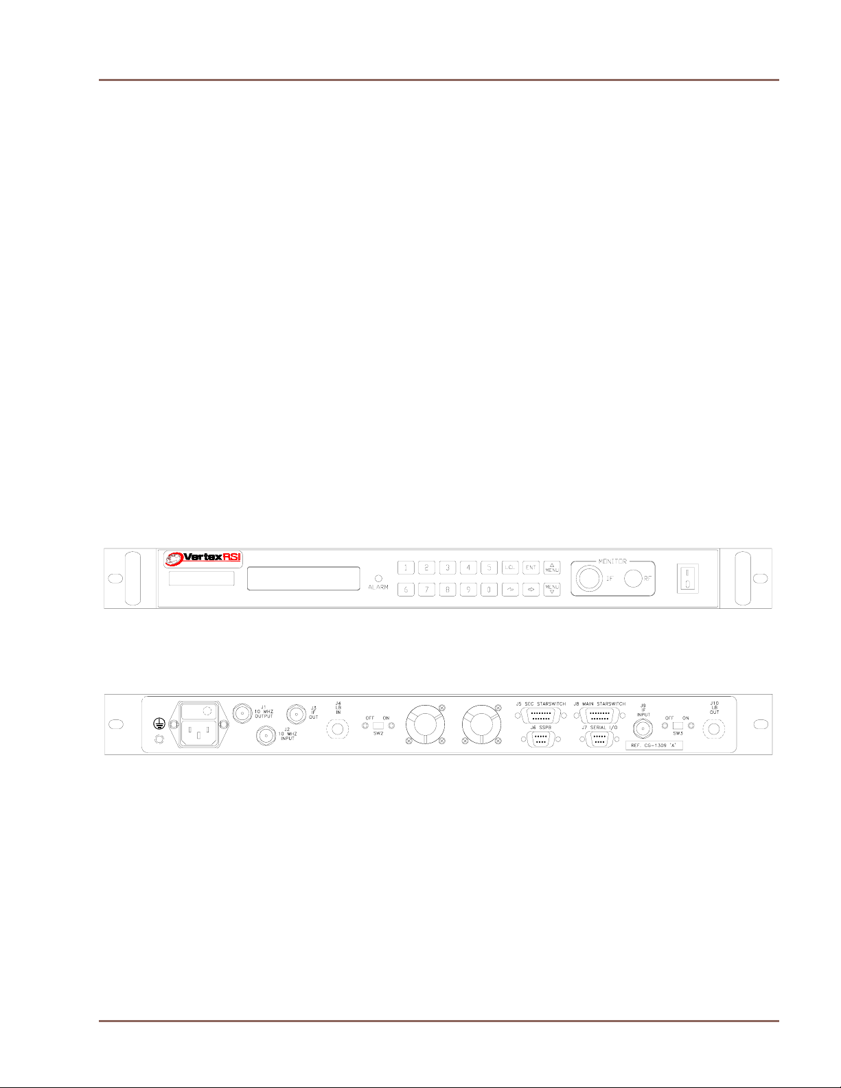
1.5 FRONT PANEL
All the operating controls and indicators for the
Integrated L-Band Up/Dn Converter are
located on the front panel. The front panel is
depicted in Figure 1-1. Alarm and level
monitoring of the L-Band Up/Dn Converter
CCA, an external LNB, and SSPB modules is
accomplished through the front panel display
and keboard interface.
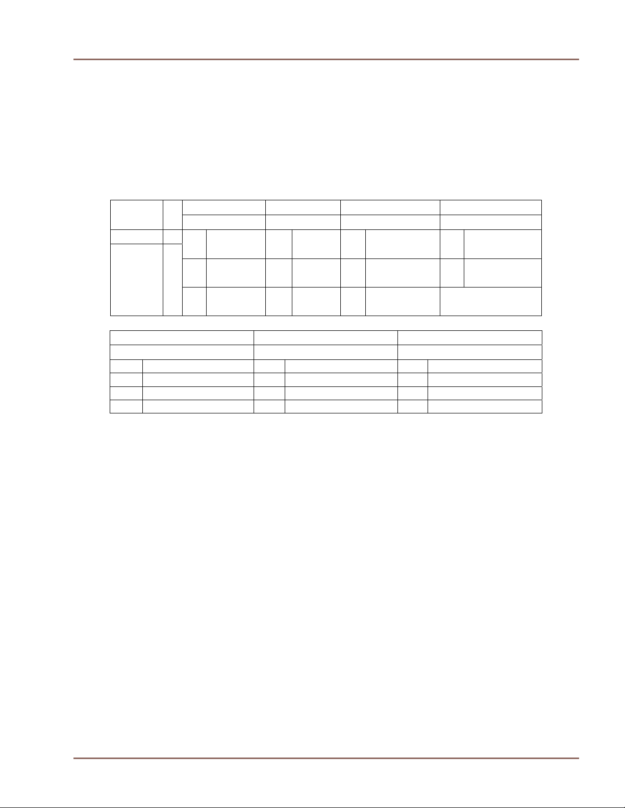
1.6 REAR PANEL
The rear panel is depicted in Figure 1-2. It
incorporates, from left to right, Grounding Lug
(GND), Power Connector, Optional 10MHz
high stability reference output (J1), 10 MHz
(J4), On/Off Switch for Dc output on J4
(SW2), Cooling Fans, Down Converter
StarSwitch Interface (Opt.) (J5), SSPB monitor
and control (J6), Remote Serial Interface (J7),
Up Converter StarSwitch Interface (Opt.) (J8),
IF In (J9), On/Off Switch for Dc output on J10
(SW3), L-Band Out (J10).
In the lower right hand side of the rear panel is
a label that refers to the operation and
maintenance manual and revision level that
applies to this converter.
1.7 COOLING
Cooling of the equipment is achieved by
pulling in cool air through the two side inlet
grills. The heated air exits the equipment
through the two rear panel mounted exhaust
fans.
reference input (J2), IF Out (J3), L-Band In
Figure 1-1 Front Panel w/Keypad and LCD Display
Figure 1-2 Rear Panel
Page 7
Page 8
Integrated L-Band Up/Dn Converter LT3600 CG-1309
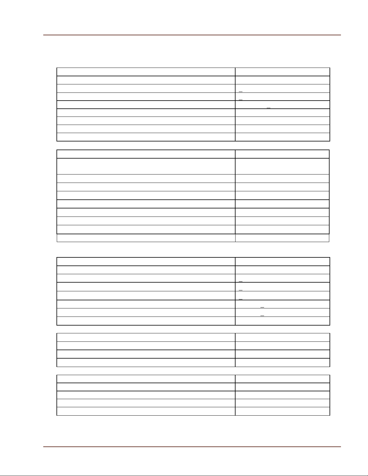
1.8 Part Number Configuration
The Part Number Selection Chart shows configuration options that are set at the factory prior to
shipment. The voltage output to J4 and J10 may be changed as required by the customer, however
this requires removal of the cover and resetting internal jumper connections. This should be
performed by qualified personnel.
1st Digit 2nd Digit 3rd Digit 4th Digit Base
Number
IF Operation L-Band Bias Voltage Ref. Oscillator
201667 - 1 70 MHZ 1 Std. 0 None 0 Std 10Mhz
2 140 MHz 2 Extend 1 D/C-22VDC
U/C-22VDC
2 D/C-22VDC
1 Hi Accuracy
10 MHz
U/C-15VDC
5th Digit 6th Digit 7th Digit
L-Band Ports 10 MHZ Ref. Out StarSwitch Ready
0 SMA Female 0 No Output 0 No
1 N-Type Female 1 U/C & D/C 1 Yes
2 U/C Only
3 D/C Only
Note: If connected to a StarSwitch, No Bias Voltage Output is allowed.
Option Descriptions:
st
1
Digit – IF Frequency, Options 3 and 4 are set for inverted spectrum.
nd
2
Digit – Standard – 950 to 1525 MHz, Extended – 950 to 1950 MHz
rd
3
Digit – Bias voltage outputs are switchable in rear panel, if selected.
th
Digit – A reference oscilator is built in to the main board. The high accuracy unit is optional.
4
th
5
Digit – D/C Input and U/C Output Port Type (J4 & J10)
th
Digit – The output from the 10 MHz reference oscilator may be connected to either or both.
6
th
7
Digit – StarSwitch Ready includes output connections to J5 and J8 for control between the
Starswitch and the LT3600.
Page 8
Page 9

Integrated L-Band Up/Dn Converter LT3600 CG-1309
Table 1-1 Integrated L-Band Specifications
UPCONVERTER
Input Frequency Range
Input Impedance
Input Level Range
Output Frequency Range
Output Impedance
Output Return Loss
Conversion Gain
Gain Linearity (over 10 dB)
Gain Linearity (over 20 dB)
Gain Stability (0 to +50 °C)
Amplitude Response (over any 36 MHz)
Amplitude Response (over 875 MHz)
Output Power (1 dB GCP)
rd
Order Intermodulation (for 2 car. each at 0 dBm o/p)
3
Spurious (at 0 dBm output)
Non-Carrier -60 dBm
Transmit Spectrum Sense
Noise Power Density -125 dBm/Hz
DOWNCONVERTER
Input Frequency Range
Input Impedance
Input Level Range
Output Frequency Range
Output Impedance
Input Return Loss
Conversion Gain
Gain Linearity (over 10 dB)
Gain Linearity (over 20 dB)
Gain Stability (0 to +50
Frequency Response (over 36 MHz)
Frequency Response (over 575 MHz)
Output Power (1 dB GCP)
Non-Carrier -55 dBm
Spurious Over 52 to 88 MHz (at 0 dBm output)
Receive Spectrum Sense
Noise Figure
°C)
50 to 90 MHz
50 Ohms
-20 to -40 dBm
950 to 1525 MHz
950 to 1950 MHz (Optional)
50 Ohms
18dB
10 to 30 dB (0.5 dB steps)
+
0.5 dB
1.0 dB
+
0.75 dB
+
0.75 dB
+
1.0 dB
+
+10 dBm (minimum)
-40 dBc
-55 dBc
Non-Inverting or Inverting
950 to 1950 MHz
50 Ohms
-75 to -35 dBm
50 to 90 MHz
50 Ohms
18dB
25 to 45 dB (0.5dB steps)
0.5 dB
+
+1 dB
+1 dB
0.75 dB
+
+1 dB
10 dBm
+
-50 dBc
Inverting or Non-Inverting
15 dB max
Page 9
Page 10
Integrated L-Band Up/Dn Converter LT3600 CG-1309
Table 1-1 Integrated L-Band Specifications
OPTIONAL INTERNAL REFERENCE
Reference Frequency
Stability (0 to +50
°C)
Aging per Day + 1 x 10⁻⁹
Output Level (rear panel) + 12 dBm +2 dB
Phase Noise @ 10 Hz -115 dBc/Hz
100 Hz -135 dBc/Hz
1 kHz -145 dBc/Hz
10 kHz < -150 dBc/Hz
UPCONVERTER and DOWNCONVERTER
Synthesizer Configuration
Tx Synthesizer and Rx Synthesizer Step Size
Parameter Memory Storage
L-Band Output Phase Noise:
at 100 Hz Offset
at 1 kHz Offset
at 10 kHz Offset
at 100 kHz Offset
at 1 MHz Offset -106 dBc/Hz
INTERNAL REFERENCE
Reference Frequency
Stability (0 to+50 °C)
Reference Output Calibration
Reference Programmable Control
Output Level (10 MHz on LB IN J4 coax)
Output Level (10 MHz on LB OUT J10 coax)
Output 2
EXTERNAL REFERENCE INPUT
Input Frequency
Input Level
nd
Harmonic
Frequency Stability
CHASSIS PHYSICAL SIZE
Height 1.75 inches
Depth 18 inches
Width 19 inches
Weight 12 lbs. max.
10.000 MHz
+ 2 x 10⁻⁸
Dual U/C and D/C with
Independent Programmability
125 kHz
Non-Volatile EEPROM
-66 dBc/Hz
-76 dBc/Hz
-86 dBc/Hz
-96 dBc/Hz
10.000 MHz
1 PPM
+
+
10 Hz
+
20 Hz
-2 dBm +
-2 dBm +
2 dB
2 dB
-40 dBc
10.000 MHz
0 to +13 dBm
As Required
Page 10
Page 11

Integrated L-Band Up/Dn Converter LT3600 CG-1309
Table 1-1 Integrated L-Band Specifications
INTERFACE AND CONNECTORS
Voltage (auto-ranging)
Internal Electronics (Power)
StarSwitch Interface Connectors (Options)
Remote Serial Interface:
115/230 VAC +
25 watts
DB-15 (Female)
DB-9 (Male)
15%
Standard: RS-422/RS-485 (J7)
External SSPB Monitor and Control (J6) DB-9 (Female)
DC Output to LNB on J4 (coaxial) (Options) 22 VDC @ 0.5 amps (max)
DC Output to SSPB on J10 (coaxial) (Options) 22 or 15VDC @ 2.0 amps (max)
Operational Temperature Range 0 to 50 °C
Page 11
Page 12

Integrated L-Band Up/Dn Converter LT3600 CG-1309
SECTION 2 Installation
2.0 INTRODUCTION
This section defines the installation requirements by which the Integrated L-Band Up/Dn
Converter will meet the published
specifications.
2.1 UNPACKING AND INSPECTION
Remove the unit from its shipping container
and inspect for any damage sustained during
shipment. Save the packing material for
reshipment back to the factory or to another
site. Report any damage to the shipping
forwarder in accordance with required
procedures.
2.2 INSTALLATION REQUIREMENTS
The LT-3600 is designed for mounting in a
standard EIA 19-inch rack. The unit must be
supported on the sides and space must be
allowed at the side of the unit to permit the
flow of cooling air. The unit should be installed
in an environment that is within the environmental envelope described in Table 1-1.
Primary power must be made available that is
within the specified limits.
2.3 MECHANICAL INSTALLATION
The chassis is equipped with threaded inserts
on either side for the installation of slides.
Slides are not provided with the unit. The front
panel is equipped with slots to accommodate
user-supplied retaining screws.
CCAAUUTTIIOONN
MOUNTING THE UNIT BY ONLY THE
FRONT PANEL WILL CAUSE EXTENSIVE
DAMAGE.
2.4 ELECTRICAL CONNECTIONS
All electrical connections are made to the rear
panel of the unit. The following describes the
rear panel connectors and its interface
requirements. The chassis ground is a #10-32
lug on the back panel.
2.4.1 Power Input
This connector is an IEC 320-C14 male and
will accept any compatible mating connector.
The power cord supplied as standard with the
unit is equipped with a NEMA 5-15P male
plug at the opposite end and is compatible with
most 115 VAC supplies. The unit is manufactured with a Universal Input Power supply that
will accept voltages in the range of 115 or 230
+/-15% VAC.
CCAAUUTTIIOONN
DAMAGE MAY RESULT IF THE INCORRECT
VOLTAGE IS APPLIED TO THE UNIT.
2.4.2 L-Band Output (J10)
This connector is selectable as an SMA or NType female. The mate (not supplied) should
be compatible with the 50-ohm coax used to
connect to the system.
CCAAUUTTIIOONN
DC OUTPUT CURRENT MAY BE PRESENT
ON J4 AND J10 DEPENDING ON POWER
OPTIONS SUPPLIED FOR THE SSPB AND
LNB.
2.4.3 IF Input (J9)
This connector is a BNC female. The male
mate (not supplied) should be compatible with
the 50-ohm coax used to connect to the system.
2.4.4 IF Output (J3)
This connector is a BNC female. The male
mate (not supplied) should be compatible with
the 50-ohm coax used to connect to the system.
2.4.5 L-Band Input (J4)
This connector is selectable as an SMA or NType female. The male mate (not supplied)
should be compatible with the 50-ohm coax
used to connect to the system.
Page 12
Page 13

Integrated L-Band Up/Dn Converter LT3600 CG-1309
2.4.6 External 10 MHz Input (J2)
This connector is a BNC female. The male
mate (not supplied) should be compatible with
the 50-ohm coax used to connect to the system.
2.4.7 SSPB Interface (J6)
This connector is a 9-pin female miniature type
“D” connector with standard #4-40 female
screw-lock hardware mounting. The mating
shell, pins, and strain relief are not supplied.
Outputs are open collector and inputs have
internal 1K full PS to +5V. The pin-out is as
follows:
Pin 1 SSPB Band Control Output -
(Low = Lo Band)
Pin 2 Amplifier Fault - Open (Hi) = ALM
Pin 3 Thermal Alarm Input –
Open (Hi) = ALM
Pin 4 Lock Alarm Input - Open (Hi) = ALM
Pin 5 Up/Dn Converter Ground
Pin 6 SSPB Attenuator/Enable Control –
(Lo = Enable)
Pin 7 Not Used
Pin 8 SSPB Detector Input + Analog 0-5V
Pin 9 SSPB Detector Input – Analog 0-5V
2.4.8 Remote Serial I/O Interface (J7)
This connector is a 9-pin male miniature type
“D” connector with standard #4-40 female
screw-lock hardware mounting. The mating
shell, pins, and strain relief are not supplied.
The electrical interface to this connector is for
a standard RS-422/485 bus. This port may be
reconfigured for RS-232 as shown below. For
bus protocol requirements, refer to Section 3-3.
The convention used for the signals is a logic
Hi for Mark (Rest) and a logic Lo for Space.
The pin-out is as follows for RS-422/485:
Pin 1 Rx Pin 2 Rx +
Pin 3 Tx +
Pin 4 Tx Pin 5 Ground
Pin 6 Alarm Relay: Common
Pin 7 Alarm Relay: Normally Closed
Pin 8 Not Used
Pin 9 Alarm Relay: Normally Open
Port J7 may be reconfigured for RS-232 interface
by changing the following jumpers locations on the
main board inside the converter:
Serial Port RS-422/485 RS-232
JP3
TXD SER 0
RXD SER 1
(Standard)
JP3
TXD SER 1
RXD SER 0
JP2 Remove Install
The pinout for RS-232 is as follows:
Pin 1 Not Used
Pin 2 Rx +
Pin 3 Tx +
Pin 4 Not Used
Pin 5 Ground
Pin 6 Alarm Relay: Common
Pin 7 Alarm Relay: Normally Closed
Pin 8 Not Used
Pin 9 Alarm Relay: Normally Open
2.4.9 High Stability 10 MHz Reference
Output (J1) (Optional Connector)
Jumpers On
1-2 5-6 7-8
9-10 11-12
17-18
3-4 5-6 7-8
9-10 11-12
19-20
Jumpers On
13-14
15-16
13-15
14-16
This connector is a BNC female. BNC jumper
cable is supplied with this option for
connection to J2.
2.5 OPERATIONAL CHECK
To verify that the basic functions of the unit are
operational, it is recommended that the
following check-out procedure be followed
prior to final system integration. If there are
any questions regarding performing the
indicated operations, refer to Section 3-3.
2.5.1 Setup
Connect the unit to a primary power source and
turn on the power switch at the front of the
unit. Verify that the power led is illuminated. If
the power led is not illuminated, check the
power cord and fuse. A spare 3.15 A fuse is
provided inside the power connector.
Switch the primary power off and connect the
IF out, LB in, IF in and the LB out at the rear
of the chassis to J3, J4, J9 and J10 respectively.
Re-establish the primary source of power. The
Front display will light and status will be
displayed.
Page 13
Page 14

Integrated L-Band Up/Dn Converter LT3600 CG-1309
SECTION 3 Operation
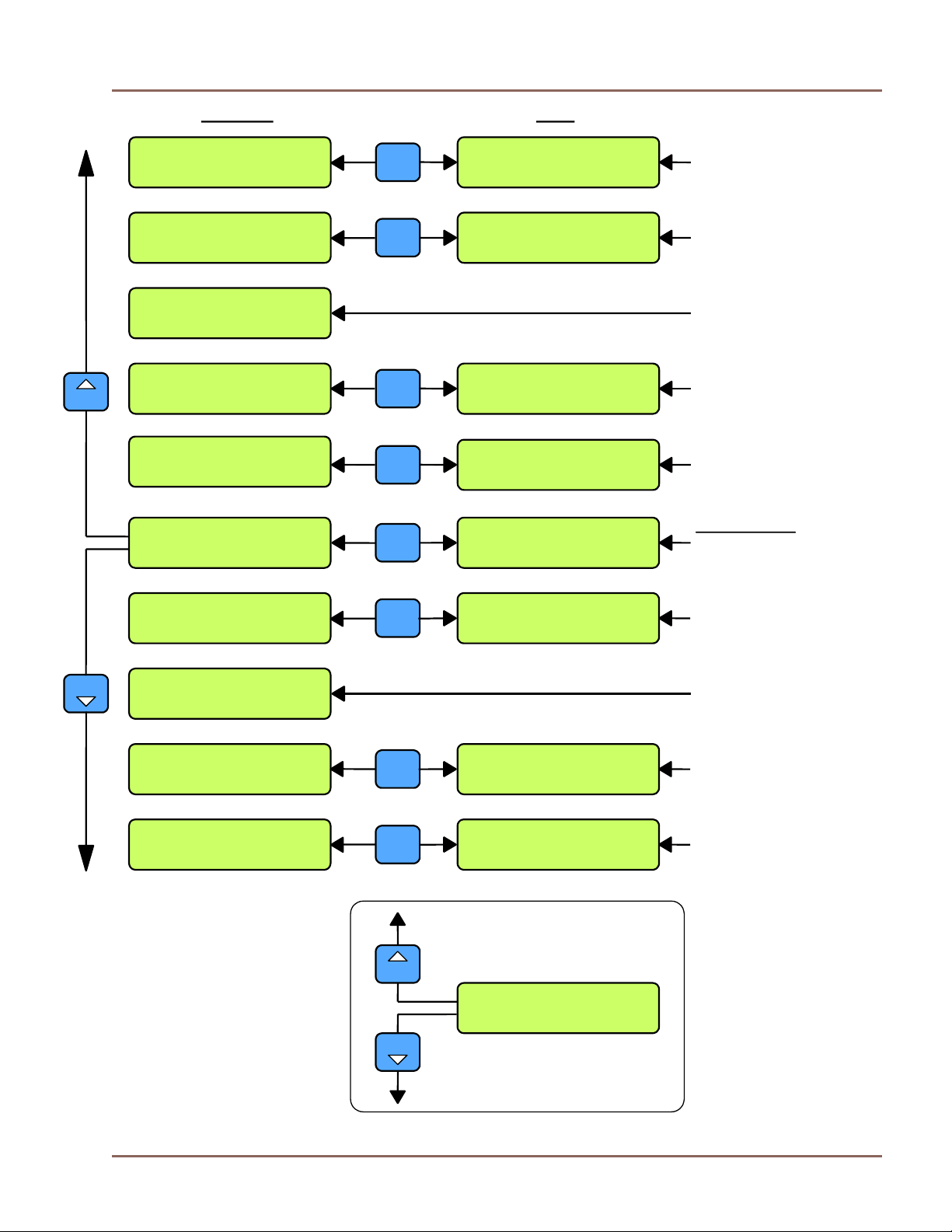
3.0 INTRODUCTION
The Up/Down Converter can be controlled
from the front panel or remotely via a serial
bus located on the rear panel of the converter.
Various menus are available for EDIT and
DISPLAY purposes.
See Figure 3-2 for a listing of the menus.
Section 4 gives a complete description of the
bus commands and conventions for operating
the converter remotely.
Red LED illuminates when any of the monitor
functions in the converter are not within pre-defined
parameters.
PLUGGED; NOT USED
UP/DOWN CONVERTER
ENT
LT3600
UC 1200.000 +25.0 dB
DC 1300.000 +35.0 dB
ALARM
2 4 3 5
6
8 9 7 0
LCL
ENT
MENU
MENU
MONITOR
IF RF
UC 1200.000 +25.0 dB
DC 1300.000 +35.0 dB
THE DISPLAY WINDOW SHOWS THE
VARIOUS SETTINGS FOR THE UNIT.
CONTROL AND STATUS MENUS
CAN BE VIEWED BY USING THE UP
AND DOWN MENUS KEYS.
USED TO MAKE FUNCTIONAL
SELECTIONS WHEN IN ANY OF
THE SET MENUS. THESE KEYS
MOVE A CURSER UNDERLINE
LEFT OR RIGHT TO ENTER
NUMERICAL DATA FROM THE
0-9 KEYS.
MENU
USED TO SCROLL THE
MENU DISPLAY UP
AND DOWN.
MENU
0
USED FOR ENTERING NUMERICAL
DATA FOR VARIOUS PARAMETER
SETTINGS. THE APPLICABLE
NUMBER IS ENTERED AT THE
CURSER UNDERLINE AND THEN
IS PRESSED TO ACCEPT THE CHANGE.
9
ENT
PRESSING THIS BUTTON
TOGGLES BETWEEN EDIT
LCL
AND DISPLAY MODE.
PRESSING THIS BUTTON
CHANGES THE PARAMETERS
ENT
ENTERED WHEN IN ANY OF THE
EDIT MENUS. IF THE
PARAMETERS ARE CHANGED
WITH THE NUMERICAL KEYPAD,
BUT IF THIS BUTTON IS NOT
PRESSED, THE PARAMETER
UNDERLINED WILL NOT CHANGE.
Figure 3-1 Front Panel Controls and Indicators
Page 14
Page 15
Integrated L-Band Up/Dn Converter LT3600 CG-1309
DISPLAY EDIT
RefOsc: OK Ofst:127
Slope Factor: 0 dB
LCL
RefOsc: OK Ofst: 127
Slope Factor: 0 dB
REFERENCE STATUS
AND CONTROL/
SLOPE FACTOR SET
Unit Address: xx
xx = 422 Mode
LCL
Unit Address: xx
xx = 422 Mode
RS 485 ADDRESS
AND STATUS
Brd SN 1234 20/12/04
S/W:v7.70 Temp: 32 C
BOARD STATUS
Front Panel SW v5.20
FP Alarm Tone: Muted
SOFTWARE VERSION
AND ALARM CONTROL
MENU
Front Panel SW v5.20
FP Alarm Tone: On
LCL
STARSW: OK ON
MODE: Auto
LCL
STARSW: OK OFF
MODE: STBY
STARswitch MODE,
AND ALARM CONTROL
UC 1200.000 +25.0 dB
DC 1300.000 +35.0 dB
LCL
UC 1000.250 +15.0 dB
DC 1500.625 +30.0 dB
DEFAULT MENU
FREQUENCY AND
GAIN SETTINGS
UC: Ovr State: On
DC: Low State: Muted
LCL
UC: Ovr State: On
DC: OK State: On
UP/DN CONVERTER
STAT U S AN D M U TE
CONTROL
MENU
UC Lvl: +1 dBm
DC Lvl: -25 dBm
DETECTOR LEVELS
SSPB: Muted Lck: Bad
Amp: OK Therm: N/A
LCL
SSPB: Muted Lck: Bad
Amp: OK Therm: Act
SSPB STATUS AND
ALARM MASK
CONTROL
LNB: OK Lvl: 380 mA
UC: Normal DC: Normal
LCL
LNB: Act Lvl: 000 mA
UC: Invert DC: Normal
LNB AND
CONVERTER STATUS
MENU BUTTONS TOGGLE
ALARMS FROM ACTIVE TO
MUTED STATES WHEN IN
MENU
EDIT MODE
SSPB: Muted Lck: Bad
Amp: OK Therm: Act
MENU
Figure 3-2 Menu Listing
Page 15
Page 16

Integrated L-Band Up/Dn Converter LT3600 CG-1309
ENTER KEY RECALLS
MEMORY TO ACTIVE
MENU
MENU
UC 0950.000 +10.0 dB
DC 1525.000 +30.0 dB
ENT
Make Satellite: 0
Active? (Yes/No) No
0
HIT ANY KEY (0-9)
Example (KEY 0)
EDIT
MENU
MENU
MENU
ESCAPES TO
ADJACENT MENU
WITHOUT RECALL
UC0 1200.000 +20.0 dB
DC0 1200.000 +30.0 dB
1
UC1 1000.125 +30.0 dB
DC1 1500.125 +45.0 dB
ENT
UC0 1200.000 +20.0 dB
LCL
CONFIRM AND STORE
CHANGE TO EACH
FIELD AND LEAVE
EDIT MODE AFTER
LAST FIELD
DC0 1200.000 +30.0 dB
ENT
MENU
SELECT MENU
ARROWS UP
OR DOWN TO
MENU
MENU
SELECT MENU
ARROW UP FOR
POSITIVE GAIN AND
MENU ARROW DOWN
FOR NEGATIVE GAIN
WHEN CURSOR IS
ACTIVE AT GAIN SIGN
SCROLL 125
KHZ STEP SIZE
WHEN
CURSOR IS
ACTIVE AT .000
UC9 1500.875 +25.0 dB
DC9 1300.875 +35.0 dB
Figure 3-3 Satellite Memory
Page 16
Page 17

Integrated L-Band Up/Dn Converter LT3600 CG-1309
3.1 StarSwitch Operation
The LT3600 UP/DOWN Converter may be used in conjunction with the StarSwitch to provide
redundancy switch over operations if configured as StarSwitch Ready. The following modes of
operation may be selected.
3.1.1 Auto Mode
Upon reaching the StarSwitch Menu the information shown in Figure 3-4 will be displayed. The
Information Window can have three selections, AUTO, STBY, or ON. The converter’s default is
AUTO. Any of the three selections stated previously can be made, and will be activated when the
ENTER key is pressed.
If a particular converter is in the AUTO mode, and an alarm is activated, it will be backed up by the
backup converter if there are no other alarms in the system. REMEMBER: ONE AND ONLY ONE
ALARM IN THE SYSTEM CAUSES A SWITCHOVER.
STARSW: OK ON
MODE: AUTO
Figure 3-4 StarSwitch Display – Auto Selection
3.1.2 StandBy Mode
When STBY has been selected, the display will change to the display shown in Figure 3-5a. In this
mode the converter with this selection will be backed up if there are no other alarms in the system.
Upon switchover to the backup converter, the display will change to Figure 3-5b indicating STBY in
the Activity Window. Under normal operation the Summary Alarm would only be ON if there were
another alarm activated on the converter, however in this case, the Summary Alarm is forced to be ON
regardless of the state of the other alarms. The operator can still view the state of alarms via the other
menus, i.e. if an alarm has been activated it will be displayed, however the Summary Alarm will
always be ON.
3.1.3 ON Mode
STARSW: OK ON
MODE: STBY
Figure 3-5 StarSwitch Display – STBY Selection
STARSW: OK STBY
MODE: STBY
When ON Mode has been selected, the display will change to the display shown in Figure 3-6. This
mode is the opposite to the STBY mode, in that the Summary Alarm is turned OFF, so even if there
was a valid alarm, the converter would not show a Summary Alarm. As in the STBY mode the
operator can still view the state of the alarms via the other menus, i.e. if an alarm has been activated it
will be displayed, however the Summary Alarm will be OFF.
NOTE: If the converter is already in STBY mode, a change to the ON mode will not occur, unless
there is no alarm in the system.
STARSW: OK ON
MODE: ON
Figure 3-6 StarSwitch Display – ON Selection
Page 17
Page 18

Integrated L-Band Up/Dn Converter LT3600 CG-1309
3.1.4 Backup Converter Operation
The Backup Converter must be programmed to store all of the Converter Frequencies and Gains in the
system, in its Satellite Memory Locations, corresponding to the Converter Number (1 to 8) labeled on
the StarSwitch Interface cables. Figure 3-7 shows the Backup Converter in Auto Mode ready to
Backup any converter in the system and after backing up Converter 2.
STARSW: OK ON 2
MODE: Auto
3.1.5 StarSwitch Alarm
STARSW: OK STBY
MODE: Auto
Figure 3-7 StarSwitch Display – Backup Converter
The StarSwitch Alarm is displayed as “Fault” in the StarSwitch Menu Window on the Backup
Converter only. A fault indicates either an internal StarSwitch Unit failure or a Power Off condition
detected on any one of the Converters in the system. The StarSwitch Alarm however, does not
activate the Summary Alarms, and the Backup Converter will still backup an Online Converter when it
is powered down. Figure 3-8 shows the Backup Converter display after Converter 1 has been powered
off and the Backup has taken over.
Figure 3-8 StarSwitch Display – Fault Indication
3.1.6 Dual StarSwitch Operation
STARSW: Fault ON 1
MODE: Auto
Each LT3600 Converter has two StarSwitch Interface connectors (J8, Main and J5, Secondary) to
control two StarSwitch Units, for systems where switching for both Up and Down Converter sections
is required. The two interfaces are not independent as an alarm in either Up or Down Converter
system will cause both to switch to the backup converter. This is necessary since a failed unit,
including both Up and Down Converter sections, will need to be removed for service. Ensure that J8,
Main Interface, is used if only one StarSwitch Unit is configured in the system.
Page 18
Page 19

Integrated L-Band Up/Dn Converter LT3600 CG-1309
3.2 Front Panel Alarm Settings
Menu Page
Active
Modes
Mask
(Default)
Comment
1) Starswitch
Front Panel
2)
Alarm Tone
Reference
3)
Oscillator
4) LNB
Lck
5) SSPB
Amp
Therm
Auto
ON
STBY
Muted
On
N/A
Act
OK
Bad
N/A
Act
OK
Bad
N/A
Act
OK
Bad
N/A
Act
OK
Bad
N/A
Act
OK
Bad
Auto
Muted
N/A
N/A
N/A
N/A
N/A
Must select "Auto" Mode when Starswitch is not present.
Forces summary alarm to OFF (see Starswitch operation).
Forces summary alarm to ON (see Starswitch operation).
Mutes audio tone when in alarm.
(has no effect on Summary Alarm condition).
Audio Tone will indicate an Alarm.
Disable Alarm if External Reference Oscillator is not present.
Activate for External Reference Alarm (select in Edit Mode).
External Reference is detected (Active Mode)
External Reference is not detected (Active Mode).
Disable Alarm if LNB (or BDC) is not present.
Activate for LNB supply current Alarm (select in Edit Mode).
LNB supply current is within acceptable range (Active Mode)
LNB supply current is not within acceptable range (Active Mode)
Disable Alarm if SSPB (or BUC) is not present.
Activate for SSPB, PLL Alarm (select in Edit Mode).
SSPB, PLL is Locked (Active Mode)
SSPB, PLL is not Locked (Active Mode)
Disable Alarm if SSPB (or BUC) is not present.
Activate for SSPB, Amplifier Summary Alarm (select in Edit Mode).
SSPB, Amplifier Summary Alarm is OFF (Active Mode)
SSPB, Amplifier Summary Alarm is ON (Active Mode)
Disable Alarm if SSPB (or BUC) is not present.
Activate for SSPB, Thermal Alarm (select in Edit Mode).
SSPB, Thermal Alarm is OFF (Active Mode)
SSPB, Thermal Alarm is ON (Active Mode)
Page 19
Page 20

Integrated L-Band Up/Dn Converter LT3600 CG-1309
SECTION 4 Serial Command Set
4.0 GENERAL
The standard Up/Dn Converter is controlled via a rear panel serial link (RS-422/485)(Reconfigurable
to RS-232). With the front panel control, a user can operate the L-Band Up/Dn Converter from its
front panel as well as from the serial link. This section describes the format for the ASCII serial
control as well as front panel operation.
Note: Some commands and status strings have been changed as of Software Release v7.70 (main
board) and v5.20 (front panel). Units marked with “Rev A” on the rear panel support the new
protocol.
4.1 LT-3600 SERIAL INTERFACE
The serial interface format to the Up/Dn Converter for RS-422 is identical to the RS-485 format
except that under RS-485, the format includes an address field (aa in the format below).
4.2 COMMUNICATION PROTOCOL
Baud Rate: 9600
Parity: None
Data Bits: Eight
Start Bits: One
Stop Bits: One
4.2.1 General Data Format
{aaCND…}
Where:
{ = Start byte
aa = 2 character address (00 to 50, remote interface only)
C = 1 character, either C (Command) or S (Status)
N = 1 number 0 to 9, A,B,C Command or Status Number
D = 1 or more Data characters (depending on command)
} = Stop byte
Note: The address is only used in the RS-485 mode when having several addressable units
communicating with one station.
Page 20
Page 21

Integrated L-Band Up/Dn Converter LT3600 CG-1309
4.3 COMMANDS
4.3.1 Set UP/Converter Frequency
{aaC1xxxxx} Where xxxx(x) = First 4 numeric data characters
Range: 0950 to 1525 (MHz) for Std. Band units
Range: 0950 to 1950 (MHz) for Extended Band units
Where (xxxx)x = Fifth character is fractional MHz as follows
0 = 0.0 MHz
1 = +0.125 MHz
2 = +0.250 MHz
3 = +0.375 MHz
4 = +0.500 MHz
5 = +0.625 MHz
6 = +0.750 MHz
7 = +0.875 MHz
Note: If only four charactors entered, 0 is assumed as fifth digit.
4.3.2 Set DOWN/Converter Frequency
{aaC2xxxxx} Where xxxx(x) = First 4 numeric data characters
Range: 0950 to 1950 (MHz) for Std and Extended Band units
Where (xxxx)x = Fifth character is fractional MHz as follows
0 = 0.0 MHz
1 = +0.125 MHz
2 = +0.250 MHz
3 = +0.375 MHz
4 = +0.500 MHz
5 = +0.625 MHz
6 = +0.750 MHz
7 = +0.875 MHz
Note: If only four charactors entered, 0 is assumed as fifth digit.
4.3.3 Set UP/Converter Gain
{aaC3xxxx} Where xxxx = 4 numeric data characters
Range: +100 to +300 (+10.0 dB to +30.0 dB)
in 0.5 dB steps
4.3.4 Set DOWN/Converter Gain
{aaC4xxxx} Where xxxx = 4 numeric data characters
Range: +250 to +450 (+25.0 dB to +45.0 dB)
in 0.5 dB steps
4.3.5 Set Internal 10 MHz Ref Oscillator Offset
{aaC5xxx} Where xxx = 3 numeric data characters
Range: 000 to 255 (0 through 10 volts)
4.3.6 Enable SSPB
{aaC6x} Where x = 0 to disable SSPB control
and x = 1 to enable SSPB control
Page 21
Page 22

Integrated L-Band Up/Dn Converter LT3600 CG-1309
4.3.7 DOWN/Converter (LNB) Spectrum Control
{aaC7x} Where x = 0 for Non-Inverting spectrum
and x = 1 for Inverting spectrum
4.3.8 UP/Converter Spectrum Control
{aaC7TXz} Where z = 0 for Non-Inverting spectrum
and z = 1 for Inverting spectrum
4.3.9 SSPB Band Control
{aaC8x} Where x = 0 for SSPB Std.Band control
and x = 1 for SSPB Extended Band control
4.3.10 Set SSPB Gain (Attenuation)
{aaC9xx) Where xx = 2 data characters (sign and number)
Range: –8 to –0 (-8 to 0 dB) or ++ for full on.
4.3.11 Enable UP/Converter
{aaCAx} Where x = 0 to disable or mute the transmitter
and x = 1 to enable or un-mute the transmitter
4.3.12 Enable DOWN Converter
{aaCBx} Where x = 0 to disable or mute the DOWN/Converter
and x = 1 to enable or un-mute the DOWN/Converter
4.3.13 Satellite Memory Store
{aaCSSxyyyyyyyyyy} Where x = Number from 0 to 9 (memory position)
y = ASCII character making up to a 10
Stores current UP and DOWN Converter Frequencies and Gains to
storage position specified along with a Text name
for that satellite is so desired.
character name for the satellite
4.3.14 Satellite Memory Recall
{aaCSRx} Where x = Number from 0 to 9 (memory position)
Recalls saved satellite settings of Frequencies and
Gains to the current set-up.
4.3.15 StarSwitch Mode Select
{aaCWx} Where x = A – Auto Mode
x = S – Standby Mode
x = O – ON Mode
Page 22
Page 23

Integrated L-Band Up/Dn Converter LT3600 CG-1309
4.4 STATUS REQUESTS
4.4.1 Command Status
{aaS1}
Returns: {aaS1bbbbccccddddeeeefffUL}
Where bbbb = Up/Converter Frequency (as above)
cccc = Down/Converter Frequency (as above)
dddd = Up/Converter Gain
eeee = Down/Converter Gain
fff = Ref. Osc. Offset
U = 0 for Non-Inverting Up/Converter, 1 for Inverting
L = 0 for Non-Inverting LNB, 1 for inverting
4.4.2 Fractional Frequency Status
{aaSF}
Returns: {aaSFxy}
Where: x = U/C Fractional Frequency (0 to 7, in 125 kHz increments)
Where: y = D/C Fractional Frequency (0 to 7, in 125 kHz increments)
4.4.3 Level Status
{aaS2}
Returns: {S2MLffppeett}
Where: M = ASCII-hex Char. MSN of bitmapped status
F indicates no alarm in group
D7 – Low = SSPB Lock Alarm
D6 – Low = SSPB Thermal Alarm
D5 – Low = SSPB Amp Alarm
D4 – Low = LNB Alarm
Where: L = ASCII-hex Char. LSN of bitmapped status
F indicates no alarm in group
D3 – Low = Ext. 10 MHz Ref. Osc. Alarm
D2 – Low = Down/Converter Synthesizer Alarm
D1 – Low = Up/Converter Synthesizer Alarm
D0 – Low = Summary Alarm
Where: ff = 2 Chars., Forward SSPB Power Detection
Range: 00 or 16 to 40 (dBm) (00 = No SSPB)
Where: pp = 2 Chars., L-Band Output Level Detection
Range: 25 to +5 (-25 to +5 dBm)
Where: rr = 2 Chars., IF Output Level Detection
Range: 25 to +5 (-25 to +5 dBm)
Where: tt = 2 Chars., on board Temperature Monitor
Range: 00 to 70 (0 to 70°C)
Page 23
Page 24

Integrated L-Band Up/Dn Converter LT3600 CG-1309
4.4.4 L-Band Status
{aaS3}
Returns: {S3bbCddTReeN}
Where: bb = 2 Chars., LNB current Detection
Range: 00 to 99 ( 0 - 990 mA)
C = 1 Character, SSPB Band Control
Range: 0 = low band, 1 = high band
dd = 2 Characters, SSPB Gain
Range: –8 to –0 or ++ (dB) ++ = Full On
T = 1 Character, Up/Converter enable
Range: 0 = disable, 1 = enable
R = 1 Character, Down/Converter enable
Range: 0 = disable, 1 = enable
ee = 2 Character, SSPB current detection
Range: 00 to 30 (0 – 3.0 A)
N = 0 for SSPB Disable, 1 SSPB Enable
4.4.5 Set Cable Slope Factor
{aaFx} Where: x = numeric character
Range: 0 to 5 (dB/500 MHz)
4.4.6 Query Cable Slope Factor
{aaF}
Returns: {F = x}
Where: x = numeric character
Range: 0 to 5 (dB/500 MHz)
4.4.7 Serial Number Read
{aaID}
Returns: {aaIDyymmddxxxx}
Where : yy = last 2 digits of year
mm = month
dd = day
xxxx = 4 digit sequence number
4.4.8 Query Software Version
{aaV}
Returns: {aaVr.ii}
Where: r = Software Release number (1 – 9)
ii = Software Issue number (00 – 99)
Page 24
Page 25

Integrated L-Band Up/Dn Converter LT3600 CG-1309
4.4.9 Query Card Type
{aaZ}
Returns: {aaZxx}
Where: xx = L-Band Card Type (1 – 8)
10 = 70 MHz IF, Std. Band Unit (SBU)
20 = 140 MHz IF, SBU
11 = 70 MHz IF, Ext Band Unit (EBU)
21 = 140 MHz IF, EBU
50 = 70 MHz IF, SBU with Inv. Up/Converter Spectrum
60 = 140 MHz IF, SBU with Inv. Up/Converter Spectrum
51 = 70 MHz IF, EBU with Inv. Up/Converter Spectrum
61 = 140 MHz IF, EBU with Inv. Up/Converter Spectrum
4.4.10 Satellite Memory Status Query
{aaSSx}
Where x = Number from 0 to 9 (memory position)
Returns: {aaSSxbbbbccccddddeeee}{aayyyyyyyyyy}
Where: x = The number of the Satellite Memory location
bbbb = Frequency for the Up/Converter
cccc = Frequency for the Down/Converter
dddd = Gain for the Up/Converter
eeee = Gain for the Down/Converter
y = ASCII character making up to a 10 character
name for the satellite
4.4.11 Satellite Fractional Frequency Status
{aaSGn}
Where: n = Number from 0 to 9 (memory position)
Returns: {aaSGnxy}
Where: n = The number of the Satellite Memory position.
x = U/C Fractional Frequency (0 to 7, in 125 kHz increments)
y = D/C Fractional Frequency (0 to 7, in 125 kHz increments)
4.4.12 StarSwitch Status
{aaSW}
Returns: {aaSWxnyz}
Where: x = O – ON (Current Status)
X = S – STBY (Current Status)
n = – No Converter Backed Up, (Space)
n = 1 – Converter 1 Backed Up, (1 to 8)
y = A – Auto Mode
y = S – STBY Mode
y = O – ON Mode
z = G – SW ALM Green (Normal)
z = R – SW ALM Red (Fault)
Page 25
Page 26
Integrated L-Band Up/Dn Converter LT3600 CG-1309
Appendix A Manual Revision History
C – Add Starsw menu M. Neely 2-03-05 D. Snyder 2-03-05 6323
B – Add Satellite Menu Info M. Neely 10-14-05 D. Snyder 10-5-05 6129
A – Gain signs M. Neely 8-15-05 D. Snyder 8-15-05 6020
- Original Release M. Neely 11-5-04 D. Snyder 11-5-04 5442
Rev. No/change Revised By Date Approved By Date ECO#
Appendix B CCA Software Revision History
7.72 StarSwitch Menu and Status Update
7.71 Added RS-485 address to Fractional Frequency Status
7.70 High/Low gains with signs, M&C changes (July 05)
7.56 1950 MHz limit, invert ref. osc. alarm (May 05)
7.55 Freq. and gain limits, fixed starswitch 485 address (Feb. 05)
7.54 Original (Jan. 05)
Appendix C Display Panel Software Revision History
5.22 StarSwitch Alarm display message is now "Fault" was "Bad".
5.21 Reversed Relay Alarm - now energized in no alarm condition.
5.20 Gain signs added, U/C Spectrum invert (July 05)
5.03 Fix Display errors (Jan. 05)
5.01 Original (Dec. 04)
Page 26
 Loading...