


Service manual
Room air conditioner
Split Wall-Mounted Type
GC/CU-S05CR
GC/CU-S07HR
GC/CU-S09HR
GC/CU-S12HR
GC/CU-S18HR
Climatic Control Corporation Wall-Mounted Split Type

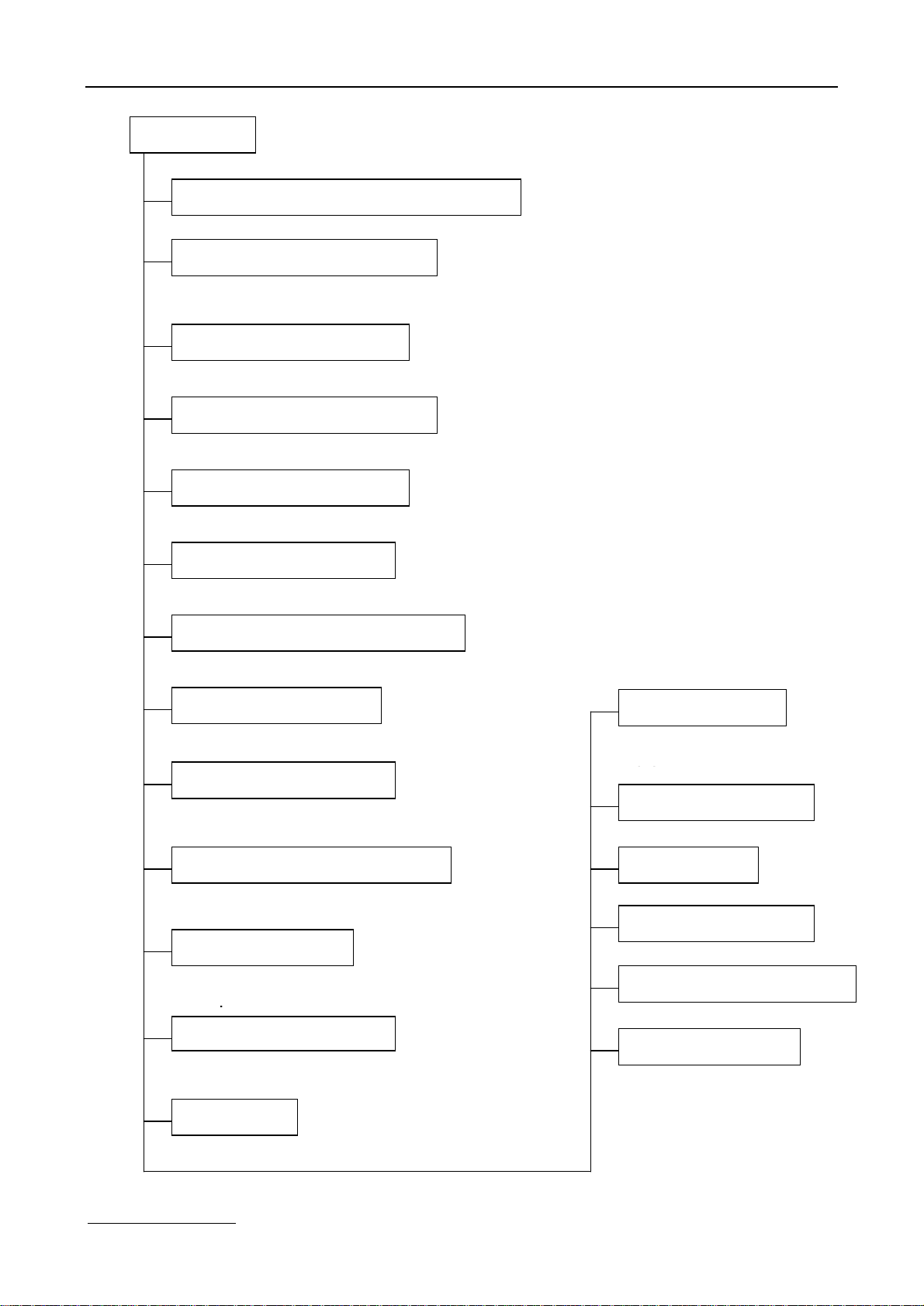
Content
1. Precaution 1
1.1 Safety Precaution 1
1.2 Warning 1
2. Function 3
3. Dimension 5
3.1 Indoor unit 5
3.2 Outdoor unit 6
4. Specification 7
5. Refrigerant cycle diagram 9
6. Operation limits 10
6.1 Cooling operation 10
6.2 Heating operation 10
7. Schematic diagram and Wiring diagram 11
7.1 Schematic diagram 11
7.2 Wiring diagram 12
8. Installation details 15
8.1 Wrench torque sheet for installation 15
8.2 Connecting the cables 15
8.3 Pipe length and the elevation 15
8.4 Air purging of the piping and indoor unit 16
8.5 Pumping down (Re-installation) 17
8.6 Re-air purging (Re-installation) 18
8.7 Balance refrigerant of the 2-way, 3-way valves 19
8.8 Evacuation 20
8.9 Gas charging 21
9. Capacity table 22
9.1 GC/GU-S05CR 22
9.2 GC/GU-S07HR 22
9.3 GC/GU-S09HR 23
9.4 GC/GU-S12HR 23
9.5 GC/GU-S18HR 24
10. Electronic function 25
10.1 Electronic control working environment 25
10.2 Proper symbols and their meaning 25
10.3 Function 25
10.4 Protection 26
10.5 Fan-only mode 26
10.6 Cooling mode 26
10.7 Dehumidifying mode 27
10.8 Heating mode 28
10.9 Defrosting mode(available for heating mode) 29
www.generalclimate.com Wall-Mounted Split Type

10.10 Auto mode 30
10.11 Force cooling function 30
10.12 Sleep mode 31
10.13 Auto restart function 31
10.14 Anion (optional) 31
11. Model and Parameters 33
12. Troubleshooting 34
12.1 Display board 34
12.2 Troubleshooting 34
12.3 Diagnostic chart 35
12.4 Resetting phenomenon often occurs during operation. 36
12.5 Operation lamp flashes and Timer lamp off. 36
12.6 Operation lamp flashes and Timer lamp on. 36
12.7 Operation lamp off and Timer lamp flashes 37
12.8 Operation lamp on and Timer lamp flashes 37
12.9 Operation lamp flashes, Timer lamp flashes . 37
13. Characteristic of temperature sensor 38
www.generalclimate.com Wall-Mounted Split Type

1. Precaution
1.1 Safety Precaution
n To prevent injury to the user or other people and property damage, the following instructions must be followed.
n Incorrect operation due to ignoring instruction will cause harm or damage.
n Before service unit, be sure to read this service manual at first.
1.2 Warning
Ø Installation
n Do not use a defective or underrated circuit breaker. Use
this appliance on a dedicated circuit.
There is risk of fire or electric shock.
n For electrical work, contact the dealer, seller, a qualified
electrician, or an Authorized service center.
Do not disassemble or repair the product, there is
risk of fire or electric shock.
n Always ground the product.
There is risk of fire or electric shock.
n Install the panel and the cover of control box securely.
There is risk of fire of electric shock.
n Always install a dedicated circuit and breaker.
Improper wiring or installation may cause fore or
electric shock.
n Use the correctly rated breaker of fuse.
There is risk of fire or electric shock.
n Do not modify or extend the power cable.
There is risk of fire or electric shock.
n Do not install, remove, or reinstall the unit by yourself
(customer).
There is risk of fire, electric shock, explosion, or
injury.
n Be caution when unpacking and installing the product.
Sharp edges could cause injury, be especially
careful of the case edges and the fins on the
condenser and evaporator.
n For installation, always contact the dealer or an
Authorized service center.
There is risk of fire, electric shock, explosion, or
injury.
n Do not install the product on a defective installation
stand.
It may cause injury, accident, or damage to the
product.
n Be sure the installation area does not deteriorate with
age.
If the base collapses, the air conditioner could fall
with it, causing property damage, product failure,
and personal injury.
n Do not let the air conditioner run for a long time when the
humidity is very high and a door or a windows is left
open.
Moisture may condense and wet or damage
furniture.
n Take care to ensure that power cable could not be pulled
out or damaged during operation.
There is risk of fire or electric shock.
n Do not place anything on the power cable.
There is risk of fire or electric shock.
n Do not plug or unplug the power supply plug during
operation.
There is risk of fire or electric shock.
n Do not touch (operation) the product with wet hands.
There is risk of fire or electric shock.
n Do not place a heater or other appliance near the power
cable.
There is risk of fire and electric shock.
n Do not allow water to run into electric parts.
It may cause fire, failure of the product, or electric
shock.
n Do not store or use flammable gas or combustible near
the product.
There is risk of fire or failure of product.
n Do not use the product in a tightly closed space for a
long time.
Oxygen deficiency could occur.
n When flammable gas leaks, turn off the gas and open a
window for ventilation before turn the product on.
Do not use the telephone or turn switches on or off.
There is risk of explosion or fire.
n If strange sounds, or small or smoke comes from
product. Turn the breaker off or disconnect the power
supply cable.
There is risk of electric shock or fire.
n Stop operation and close the window in storm or
hurricane. If possible, remove the product from the
window before the hurricane arrives.
www.generalclimate.com 1 Wall-Mounted Split Type

There is risk of property damage, failure of product,
or electric shock.
n Do not open the inlet grill of the product during operation.
(Do not touch the electrostatic filter, if the unit is so
equipped.)
There is risk of physical injury, electric shock, or
product failure.
n When the product is soaked (flooded or submerged),
contact an Authorized service center.
There is risk of fire or electric shock.
n Be caution that water could not enter the product.
There is risk of fire, electric shock, or product
damage.
n Ventilate the product from time to time when operating it
together with a stove, etc.
There is risk of fire or electric shock.
n Turn the main power off when cleaning or maintaining
the product.
There is risk of electric shock.
n When the product is not be used for a long time,
disconnect the power supply plug or turn off the breaker.
There is risk of product damage or failure, or
unintended operation.
n Take care to ensure that nobody could step on or fall
onto the outdoor unit.
This could result in personal injury and product
damage.
Ø CAUTION
n Always check for gas (refrigerant) leakage after
installation or repair of product.
Low refrigerant levels may cause failure of product.
n Install the drain hose to ensure that water is drained
away properly.
A bad connection may cause water leakage.
n Keep level even when installing the product.
To avoid vibration of water leakage.
n Do not install the product where the noise or hot air from
the outdoor unit could damage the neighborhoods.
It may cause a problem for your neighbors.
n Use two or more people to lift and transport the product.
Avoid personal injury.
n Do not install the product where it will be exposed to sea
wind (salt spray) directly.
It may cause corrosion on the product. Corrosion,
particularly on the condenser and evaporator fins,
could cause product malfunction or inefficient
operation.
Ø Operational
n Do not expose the skin directly to cool air for long
periods of time. (Do not sit in the draft).
This could harm to your health.
n Do not use the product for special purposes, such as
preserving foods, works of art, etc. It is a consumer air
conditioner, not a precision refrigerant system.
There is risk of damage or loss of property.
n Do not block the inlet or outlet of air flow.
It may cause product failure.
n Use a soft cloth to clean. Do not use harsh detergents,
solvents, etc.
There is risk of fire, electric shock, or damage to the
plastic parts of the product.
n Do not touch the metal parts of the product when
removing the air filter. They are very sharp.
There is risk of personal injury.
n Do not step on pr put anything on the product. (outdoor
units)
There is risk of personal injury and failure of
product.
n Always insert the filter securely. Clean the filter every
two weeks or more often if necessary.
A dirty filter reduces the efficiency of the air
conditioner and could cause product malfunction or
damage.
n Do not insert hands or other object through air inlet or
outlet while the product is operated.
There are sharp and moving parts that could cause
personal injury.
n Do not drink the water drained from the product.
It is not sanitary could cause serious health issues.
n Use a firm stool or ladder when cleaning or maintaining
the product.
Be careful and avoid personal injury.
n Replace the all batteries in the remote control with new
ones of the same type. Do not mix old and mew batteries
or different types of batteries.
There is risk of fire or explosion.
n Do not recharge or disassemble the batteries. Do not
dispose of batteries in a fire.
They may burn of explode.
n If the liquid from the batteries gets onto your skin or
clothes, wash it well with clean water. Do not use the
remote of the batteries have leaked.
The chemical in batteries could cause burns or
other health hazards.
www.generalclimate.com 2 Wall-Mounted Split Type
2. Function
Indoor unit
Operation ON/OFF by remote controller
Sensing by room temperature
Room temperature sensor.
Pipe temperature sensor.
Room temperature control
Maintain the room temperature in accordance with the setting temperature.
Starting temperature control
Indoor fan is delayed for 5 sec at the
Time Delay Safety control
Restarting is for approx. 3 minutes..
Indoor fan speed control
High, med, low, breeze.
Operation indication Lamps (LED)
Light up in the LED (LCD) for each operation mode.
Two-direction air vane
The unit will decide the louver direction according to operation mode.
Sleep mode auto control
The fan is turn to low speed (cooling/heating).
The unit will be turn off after seven hours.
Independent dehumidification
The function is usually used in rainy days in
springtime or damp areas.
Self-diag. function
The function will be
operate in any operation
Anti-cold function
Prevent the cold wind at
the beginning of unit
Temp. Compensation
Defrost mode
Auto-restart function
Flexible wiring connection
Air flow Direction control
The louver can be set at the desired position or swing up
and down automatically
Auto mode
The unit can be change by the room temperature.
www.generalclimate.com 3 Wall-Mounted Split Type
Easy clean panel

Outdoor unit
Power relay control
The unit has 3 mins delay between continuously ON/OFF operations.
Low ambient kit
The unit can operate in cooling mode at low ambient temperature conditions.
Low noise air flow system
Bird tail propeller fan makes the outdoor unit run more quietly.
Hydrophilic aluminum fin
The hydrophilic fin can improve the heating efficiency at operation mode.
4 way valve control
It is only operated in the heating operation mode except defrosting operation.
Discharge pipe temperature protect
Anti-rust cabinet
Made from electrolytic zinc steel sheet and anti-rust coated components.
Valve protection cover
It protects the valves and prevents water from dripping.
www.generalclimate.com 4 Wall-Mounted Split Type
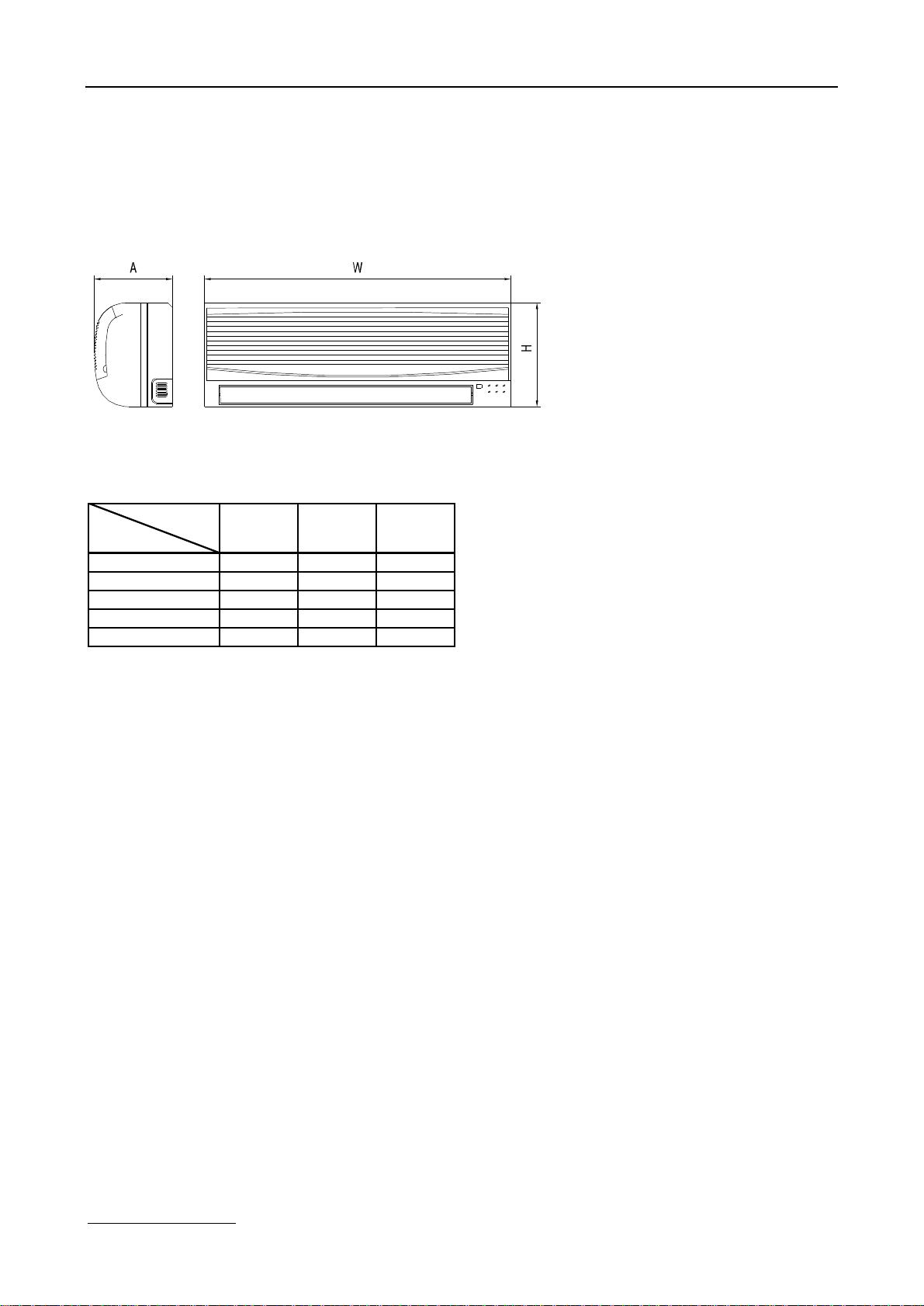
3. Dimension
3.1 Indoor unit
Dimension
Mode
5K750250188
7K750250188
9K750250188
12K750250188
18K906286235
WHL
www.generalclimate.com 5 Wall-Mounted Split Type

458
280
540
458
280
540
458
280
540
530
315
590
3.2 Outdoor unit
Dimension
Mode
5K700535235
7K700535235
9K700535235
12K780540250
18K760590285540335615
WHDL1L2L3
www.generalclimate.com 6 Wall-Mounted Split Type
GC/GU-S05CR
GC/GU-S07HR
m3/h
Ф
Ф
m
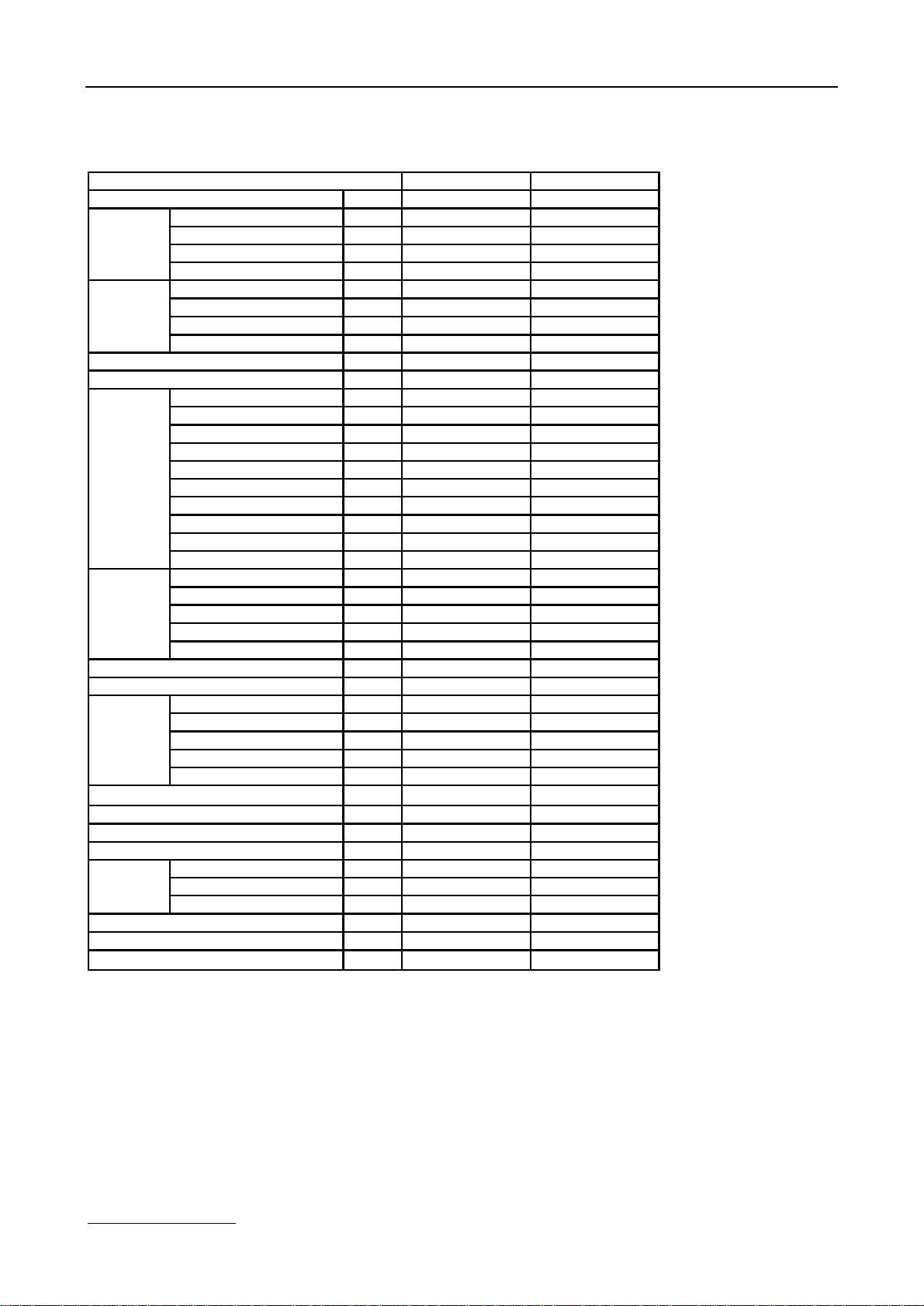
4. Specification
Model
Power supply
Capacity Btu/h
Cooling
Heating
Max. current
Starting current
Compressor
Indoor
fan motor
Indoor air flow (Hi/Mi/Lo)
Indoor noise level (Hi/Mi/Lo)
Outdoor
fan motor
Outdoor air flow
Outdoor noise level
Refrigerant type R22
Design pressure
Refrigerant
piping
Operation temp
Ambient temp
Application area
Input W560760
Rated current A2,63,6
EER Btu/w.h99,2
Capacity Btu/h
Input W
Rated current A
COP W/W
Model
Type
Brand
Capacity Btu/h57007500
Input W590725
Rated current(RLA) A2,73,4
Locked rotor Amp(LRA) A1315
Thermal protector BF540-KBMRA98854
Capacitor uF
Refrigerant oil ml
Model
Brand WELLINGWELLING
Input W
Capacitor uF
Speed(hi/mi/lo) r/min1020/ 960/ 9001020/ 960/ 900
Model
Brand WELLINGWELLING
Input W
Capacitor uF
Speed r/min
Liquid side/ Gas side mm
Max. refrigerant pipe length m1010
Max. difference in level m55
Ph-V-Hz
1, 220-240V~,50Hz1, 220-240V~,50Hz
50007000
-----
7600
-----760
-----3,4
-----
10
A3,85
A
SHANGHAI SENLIN
1618
KH104VFHC
Rotary
15
MS-56 270
2P14C235ANA
Rotary
GD Matsushita
25
ATOMOS M60 270
RPG13HRPG13H
36,536,5
1.2μF/450V1.2μF/450V
m3/h
dB(A)
300/270/240380/350/320
32/30/2832/30/28
YDK24-6TYDK24-6T
7070
33
850850
14001400
dB(A)4949
g
MPa
℃
℃
2
480620
2,62,6
6.35/Ф9.53
6.35/Ф9.53
17-3017-30
18-45-7 - 45
8-1210-14
Note:
The noise date is base on hemi-anechoic chamber, during actual operation; these values are normally
somewhat different as a result of ambient condition.
The above design and specifications are subject to change without prior notice for product improvement.
www.generalclimate.com 7 Wall-Mounted Split Type
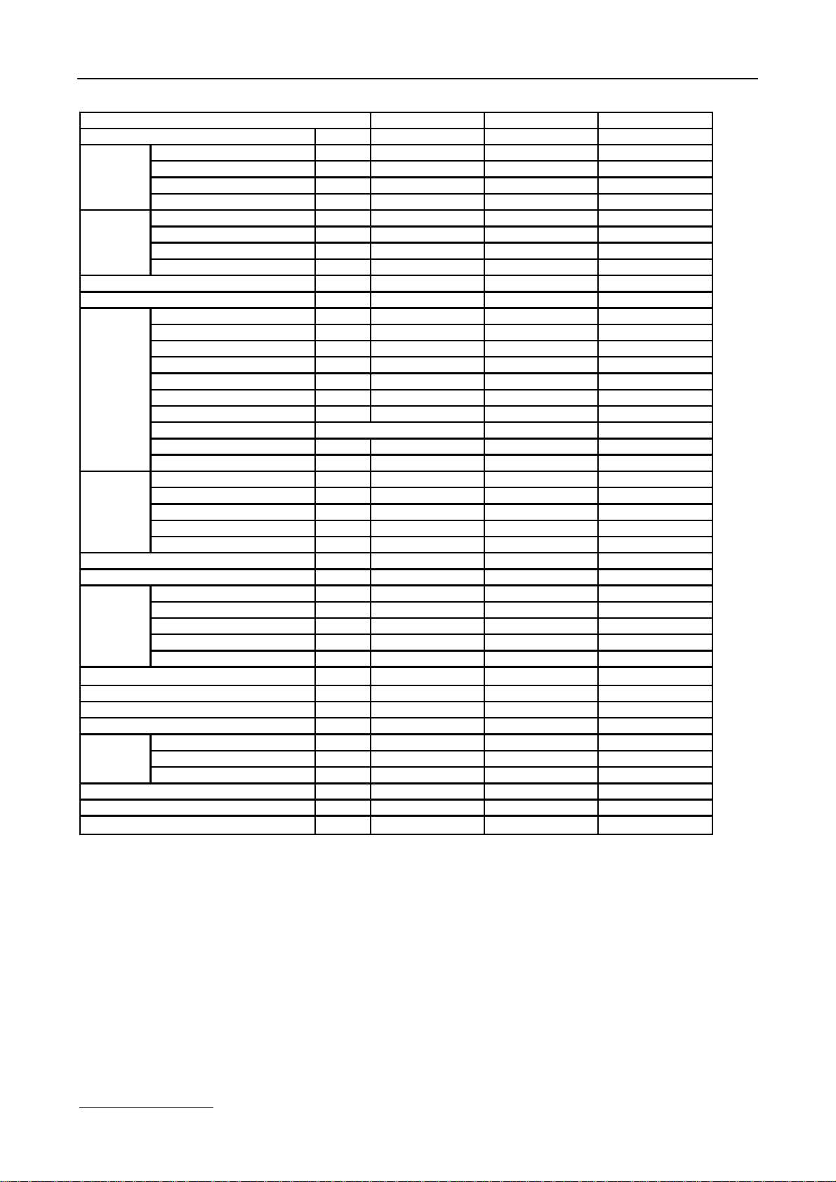
GC/GU-S09HR
GC/GU-S12HR
GC/GU-S18HR
)
m3/h
Ф
Ф
Ф
m
Model
Power supply
Capacity Btu/h90001200018000
Cooling
Input W96012301920
Rated current A4,55,79
EER Btu/w.h9,49,89,4
Capacity Btu/h100001300020000
Heating
Input W98012901980
Rated current A4,469,2
COP W/W10,29,810,1
Max. current
Starting current
Model 2P18S225ANKPH225X2C-4FT
Type RotaryRotary
Brand GD MatsushitaGD Toshiba
Capacity Btu/h99201361017620
Compressor
Input W97013051725
Rated current(RLA) A4,56,18,1
Locked rotor Amp(LRA) A242636
Thermal protector External(MRA98745
Capacitor uF3035
Refrigerant oil mlSUNISO 350430
Model
Indoor
fan motor
Brand WELLINGWellingWELLING
Input W
Capacitor uF
Speed(hi/mi/lo) r/min1100/1020/95013501180
Indoor air flow (Hi/Mi/Lo)
Indoor noise level (Hi/Mi/Lo)
Model
Outdoor
fan motor
Brand WELLINGWELLINGWELLING
Input W5572
Capacitor uF
Speed r/min800850
Outdoor air flow
Outdoor noise level
Refrigerant type R410A
Design pressure
Refrigerant
piping
Liquid side/ Gas side mm
Max. refrigerant pipe length m101015
Max. difference in level m558
Operation temp
Ambient temp
Application area
Ph-V-Hz
1, 220-240V~,50Hz1, 220-240V~,50Hz1, 220-240V~,50Hz
A79,110
A2526
SHY33MC2-U
ExternalInternal
m3/h
dB(A)
RPG13H
36,5
1.2μF/450V
450/420/390
37/34/31
RPG13H
36,5
1,2
550/500/460
41/ 38 /34
RPG25
1.5uF/450V
750/710/650
41/38/35
YDK24-6TYDK24-6YDK25-6H
2.5μF/450V2.5μF/450V2.5μF/450V
150018002000
dB(A)505254
g650820
MPa
℃
℃
2
2,6
6.35/Ф9.53
17-30
2,6
6.35/Ф12.7
17-30
6.35/Ф12.7
-7 - 45-7 - 45-7 - 45
14-2118-2625-35
36
rotary
Hitachi
50
600
53
96
900
1370
2,6
17-30
Note:
www.generalclimate.com 8 Wall-Mounted Split Type
The noise date is base on hemi-anechoic chamber, during actual operation; these values are normally
somewhat different as a result of ambient condition.
The above design and specifications are subject to change without prior notice for product improvement.

5. Refrigerant cycle diagram
Ø Cooling only
Ø Heat pump mode
www.generalclimate.com 9 Wall-Mounted Split Type

6. Operation limits
6.1 Cooling operation
Outdoor unit air temp.℃ DB
Indoor air temp. ℃ DB
Note: The chart is the result from the continuous operation under constant air temperature conditions. However, excludes the
initial pull-down stage.
6.2 Heating operation
Indoor air temp. ℃ DB
Outdoor unit air temp.℃ DB
Note: The chart is the result from the continuous operation under constant air temperature conditions. However, excludes the
initial pull-down stage.
www.generalclimate.com 10 Wall-Mounted Split Type
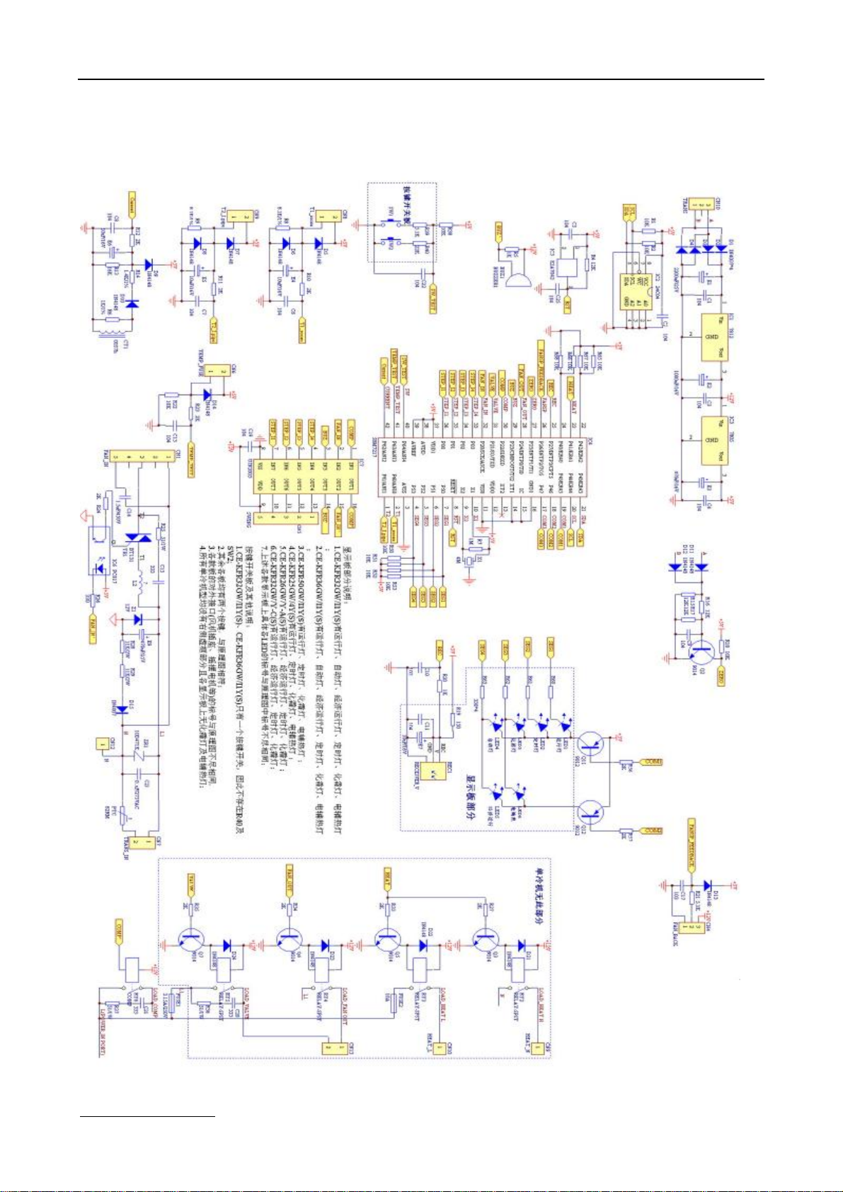
7. Schematic diagram and Wiring diagram
7.1 Schematic diagram
www.generalclimate.com 11 Wall-Mounted Split Type
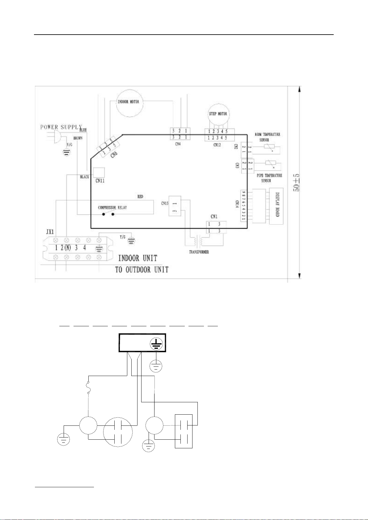
7.2 Wiring diagram
7.2.1 Cooling mode
GC/GU-S05CR
INDOOR UNIT
OUTDOOR UNIT
OVERLOAD
RELAY
COMPRESSOR
Y& G
C
S
BLACK
RED
BLUE
BLACK
R
COMPRESSOR
CAPACITOR
1 2︵N︶
RED
MOTOR
Y& G
FAN
Y& G
BLACK
RED
RED
BLUE
FAN
CAPACITOR
www.generalclimate.com 12 Wall-Mounted Split Type
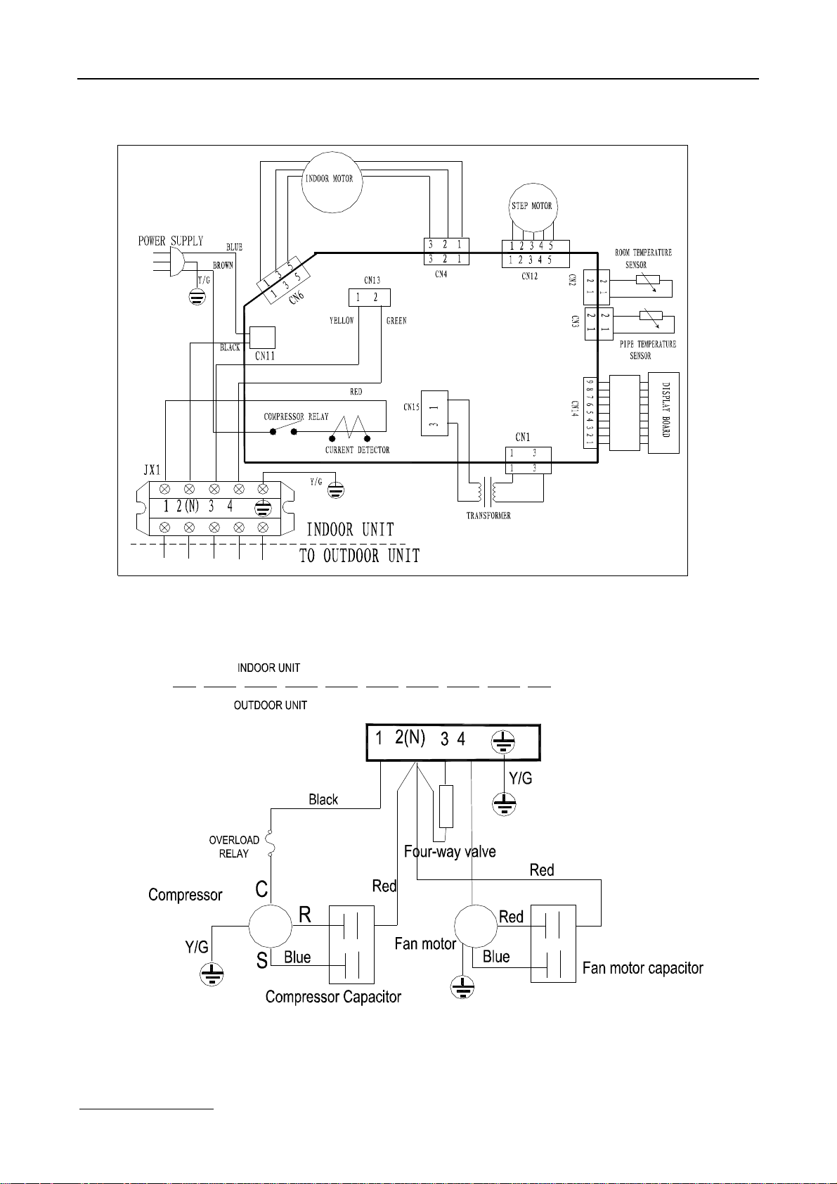
7.2.2 GC/GU-S07HR, GC/GU-S09HR, GC/GU-S12HR
www.generalclimate.com 13 Wall-Mounted Split Type

MSG-18HR
www.generalclimate.com 14 Wall-Mounted Split Type
length
Btu/h
GAS
LIQUID
B (m)A
(m)
(g/m)
3/8’’ (φ9.52)
1/4’’ (φ6.35)
5510301/2’’ (φ12.7)
1/4’’ (φ6.35)
55103018K1/2’’ (φ12.7)
1/4’’ (φ6.35)
5815
30
In case that more
8. Installation details
8.1 Wrench torque sheet for installation
Outside diameter
Torque
mminchKg.m
φ6.351/41.8
φ9.523/84.2
φ12.71/25.5
φ15.885/86.6
φ19.053/46.6
8.2 Connecting the cables
The power cord of connect should be selected according to the following specifications sheet.
Grade
Unit7K9K12K18K
mm21,01,01,52,5
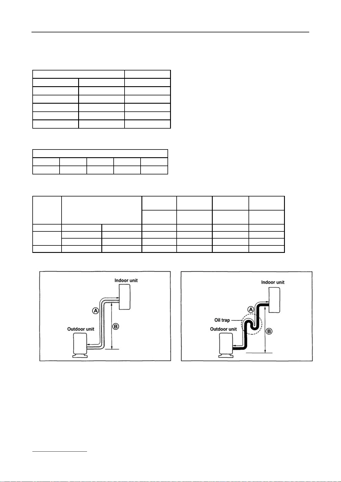
8.3 Pipe length and the elevation
Capacity
7k~12K
Standard
Pipe size
(m)ElevationElevationrefrigerant
Max.Max.Additional
than 5m.
Caution:
Capacity is base on standard length and maximum allowance length is base of reliability.
Oil trap should be install per 5-7 meters.
www.generalclimate.com 15 Wall-Mounted Split Type
 Loading...