

Page 1

TM
Aspen
AEVK-01 User
Manual
Ultra Wideband Transceiver
General Atomics Photonics Division
10240 Flanders Court
San Diego, CA 92121
http://photonics.ga.com/uwb
Tel: (858) 457-8749
Fax: (858) 457-8746
Email: jeff.harris@ga.com
April 2005
Version 1.0.4
Copyright General Atomics 2005
Page 2

Nondisclosure Provisions
This manual contains General Atomics Corporation Confidential and Proprietary
information. All developers utilizing this evaluation kit and its documentation are
reminded of their obligations to protect General Atomics Proprietary information.
Copyright
©2005 General Atomics. All rights reserved.
Trademarks
Aspen and Spectral Keying are registered trademarks of General Atomics Corporation.
Rights
Rights to use this documentation are restricted to the terms set forth in the Terms and
Conditions accompanying this AEVK-01 Evaluation Kit.
Regulatory Notice
This device does not comply with any RF emissions regulations in any country. Users
should consult their spectrum management authorities before use.
U.S. Operation
subject to the following conditions: (1) this device may not cause harmful
interference; (2) this device must accept any interference received, including
interference that may cause undesired operation; (3) this device must be operated
indoors; and (4) the emissions from equipment operated under this section shall not
be intentionally directed outside of a building where the equipment is located, such as
through a window or doorway, to perform an outside function, and
outdoor mounted antennas or any other outdoor antenna infrastructure is prohibited.
Operation in disregard of these conditions is a violation of 47 U.S.C. 301 and could
subject the operator to serious legal penalties.
Outside U.S. Operation
authorized for use or commercial exploitation under the regulations on any non-U.S.
government agency. Please consult with your government’s local regulatory agency
to ensure proper authorizations are obtained.
: This device complies with the Part 15 of the FCC rules. Operation is
(5) the use of
: This AspenTM UWB transceiver technology has not been
2
This document contains proprietary information subject to the terms and
conditions of General Atomics Aspen Developers Program Nondisclosure
Agreement
Page 3

Table of Contents
Revision History....................................................... 4
Spectral Keying® Ultra Wideband Modulation.......... 5
Applications ............................................................. 7
Basic Connection.................................................... 10
Connecting The System For Data Streaming Operation................ 11
RF Test Mode ....................................................................... 12
Summary .......................... Error! Bookmark not defined.
Antenna Characteristics ......................................... 14
3
This document contains proprietary information subject to the terms and
conditions of General Atomics Aspen Developers Program Nondisclosure
Agreement
Page 4

Revision History
Revision Date Author Comments
November 1st, 2005 L. Chow Initial creation.
March 25th, 2005 R. Erman Added instructions on RF
Test Mode
March 31st, 2005 R. Erman Moved programming
portion Tech Note 4001.
April 5th, 2005 R. Erman Added Information
regarding AEVK
companion CD.
4
This document contains proprietary information subject to the terms and
conditions of General Atomics Aspen Developers Program Nondisclosure
Agreement
Page 5
Introduction
Congratulations on your purchase of the General Atomics AEVK-01 ultra
wideband (UWB) transceiver evaluation kit! This evaluation kit contains all of
the hardware, software and documentation necessary to evaluate an FCCcompatible high data rate UWB transmission system. As the first generation of
the Aspen
the AspenTM 2000 UWB multi-chip module (MCM) based chipset, including the
physical layer, baseband, and the embedded media access control (MAC)
functions necessary to accomplish low-power wireless multimedia streaming.
TM
family of UWB radios, the AEVK-01 is a discrete implementation of
This User’s Guide describes the functional capabilities of the Aspen system, the
advantages of the Spectral Keying
®
(SK) modulation technique employed in
the radio, its operational characteristics, and application interfaces. The AEVK01 is designed to provide product development OEMs and ODMs confidence in
the robust RF performance of the SK-based UWB radio and provides all of
information necessary to develop and test applications.
Detailed timing and interface specifications are provided separately with
General Atomics developer’s agreement.
Spectral Keying® Ultra Wideband Modulation
SK modulation is fundamentally different from other UWB approaches,
optimized for robust long-range operation in high multipath application
environments. The SK modulation approach divides the allocated UWB
spectrum into multiple sub-bands, each with 500 MHz minimum bandwidth.
This provides flexibility in selecting suitable bands (spectral agility) based on
the presence of interference or regulatory constraints. In the SK modulation
architecture used in the AEVK-01, information symbols are made up of 5
pulses, each sent in a different UWB sub-band. The combination of the five sub
bands creates a symbol, where information is encoded in the sequence of the
bands used for each pulse. Each frequency is used only once in a symbol. An
individual sub band sample is shown below:
5
This document contains proprietary information subject to the terms and
conditions of General Atomics Aspen Developers Program Nondisclosure
Agreement
Page 6
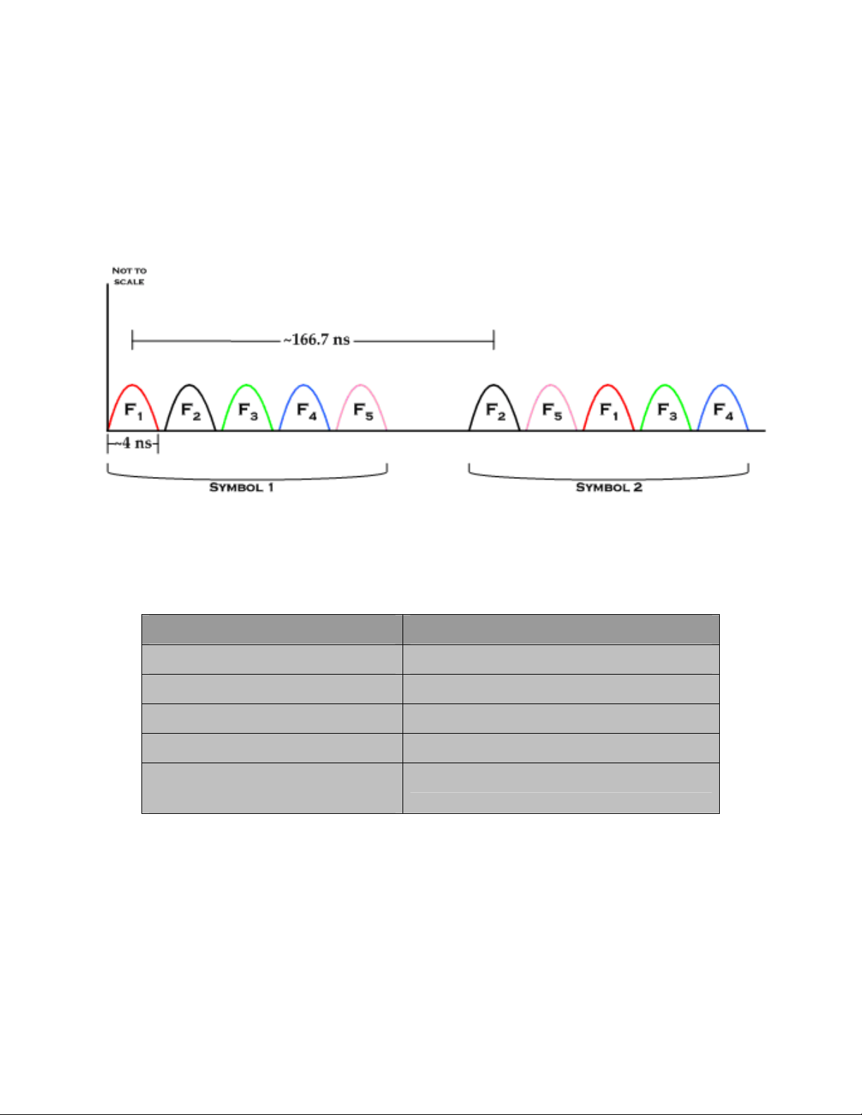
Using 5 bands, the allowable symbol set is 5!=120 unique symbols. Hence the
number of possible bits per symbol is log2(120) = 6.9 bits. Figure 1 illustrates
the advantage of SK its capability to carry a large number of bits per symbol
showing two typical SK symbols. The first symbol uses the sequence of subbands F
, F4 to a different another symbol. The result is a symbol set with great
F
3
, F2, F3, F4, F5 to create a unique symbol, while the second F2, F5, F1,
1
spectral agility, but with sufficient time between symbols to effectively capture
multipath energy.
Figure 1: Typical SK symbols
The following are the key parameters employed in the AEVK-01:
Parameter Value
Symbol repetition frequency 6 MHz
No of pulses per symbol 5
Bandwidth per pulse >500 MHz
No of frequency sub-bands 5
Nominal Center Frequency
3.48, 4.02, 4.56, 6.12, 6.96 GHz
of sub-bands (GHz)
Note: all five sub-bands must transmit in each symbol period. No information is
contained in any single sub-band, and Aspen has no ability to dwell on any single
sub-band.
Interference Potential of SK:
To a victim narrowband receiver (BW < 500 MHz), SK waveform will look like
an impulse radio waveform, that has ~ 4 ns pulse length, ~ 500 MHz BW and
6 MHz PRF. Such signal has been anticipated in the FCC R&O and its
6
This document contains proprietary information subject to the terms and
conditions of General Atomics Aspen Developers Program Nondisclosure
Agreement
Page 7

interference impact analyzed before issuing the rules. Therefore interference
from an SK transmitter will be very low.
Applications
Since February 2002, when the FCC opened the door to unlicensed
communication systems based on UWB technology, industry has been
anticipating high bandwidth (>10 Mbps), short range (<30m) wireless
solutions based on this technology. The
offering data rates up to 80 Mbps at ranges of 10 meters and beyond. Robust
in both data rate and performance in high multipath indoor applications, Aspen
is ideal for streaming video, streaming audio, and in the future, data exchange
applications such as USB and 1394.
Applications for the Aspen UWB radio include video cable replacement (realtime streaming of content from DVD/DVR/satellite receivers/security cameras
to television monitors), audio entertainment systems (file transfer or streaming
between PC-based platforms and audio receivers, and portable music
systems), and more.
The General Atomics Aspen family of UWB transceivers was developed
specifically to address these types of demanding application environments –
indoor operation, effective operation through walls and other home
construction material, and peaceful co-existence with other wireless home
networking solutions such as garage door openers, 802.11a/b/g networks,
microwaves, and other RF interferers. Most importantly,
UWB has been proven to operate effectively in dynamic multipath
environments, defined as the presence of people moving between transmit and
receive antennas.
Aspen solution meets this promise by
Aspen’s SK-based
AEVK-01 accepts data into a general purpose FIFO through Serial Parallel
Interface (SPI) port. Any type of data source can be connected on the transmit
side and sent to an AEVK-01 receiver. Data rates vary depending on the radio
settings and forward error correction (FEC) coding employed. A typical scenario
would use a 2/3 FEC coding, allowing for up to 50 Mbps of (application) data to
be transmitted over a single transmitter. In this configuration, one transmitter
could carry up to two high-definition (HD) or four standard definition (SD)
video streams.
The AEVK-01 is designed to be used with a customer supplied external codec.
The codec inputs data into the AEVK-01 radio in accordance with the provided
interface and timing specification document. No external drivers are needed to
operate the AEVK-01 in its operational mode, although drivers and external
hardware may be required to interface and monitor specific applications over
the radios. When an external application is attached to the AEVK-01, the radio
will operate in its basic streaming mode, point to multipoint broadcast. All
7
This document contains proprietary information subject to the terms and
conditions of General Atomics Aspen Developers Program Nondisclosure
Agreement
Page 8

AEVK-01 units are shipped in this configuration unless otherwise specified by
the customer.
In cases where an external application is not available, the AEVK-01 can also
be configured into an RF Test Mode that streams representative video data
through the UWB transmitter. The RF Test Mode can be utilized without a
required external application, and even when an Aspen receiver is not present.
This mode provides an RF output signal consistent with an external video
codec. Instructions for configuring the RF Test Mode are included in the
companion CD that is shipped with all AEVK01 units from General Atomics.
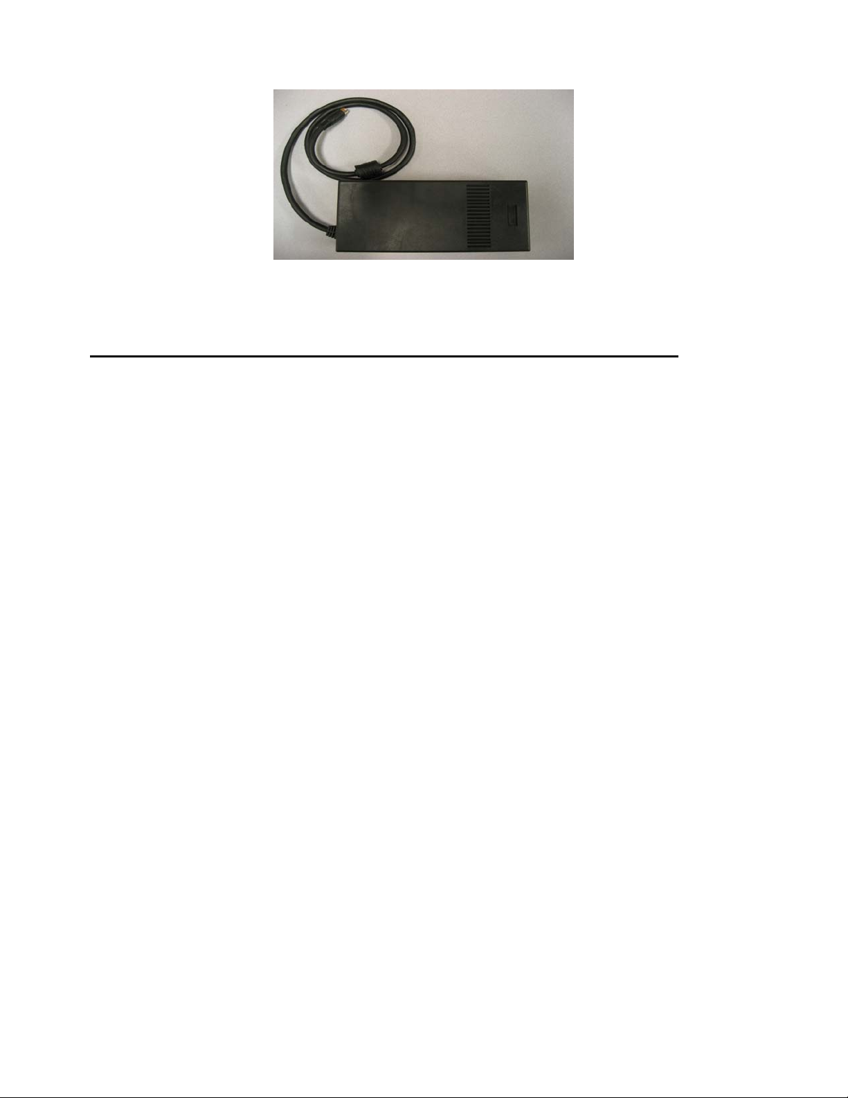
The elements of the AEVK-01 are shown
in the accompanying photo, including
the radio transceiver with antenna, and
power supply. This photo shows the
antenna exposed without the
accompanying antenna cover. A knob
at the top of the antenna cover allows
the user to point the antenna for fine
tuning link quality.
8
This document contains proprietary information subject to the terms and
conditions of General Atomics Aspen Developers Program Nondisclosure
Agreement
Page 9

Getting Started
First, please check the contents of the package. Each AEVK-01 should contain
the following items:
Qty Item
2 AEVK -01 Transceivers
2 Power supplies with cords
2 Integrated UWB antennas
2 SCSI to DB9 cables
1 Interface and Timing Specification Document
1 RF Test Mode Connector
1 Companion CD
Each connector and switch on the AEVK-01 transceiver’s back panel is labeled
as to its function.
Starting from the far left, the reset button performs an overall soft reset of the
radio, forcing it to purge all data currently in the system and reestablishing
either transmit or receive
functions. Reset is useful in
situations when the radio doesn’t
respond properly due to faulty
data from an external
application.
The Auxiliary Port has two main
functions. At start-up, the Aux
port can be used to program
radio operational features such
as data rate and FEC rate. It is
also used as the interface to
configure the radio between
normal and RF Test modes.
9
This document contains proprietary information subject to the terms and
conditions of General Atomics Aspen Developers Program Nondisclosure
Agreement
Page 10

Once the radio is configured, the Aux port acts as the main data interface into
the transmitter and out of the receiver. Details on normal operation and RF
Test Mode programming and interface methods are addressed in their
respective sections.
The Power-On LED in the center of the panel illuminates when the radio is
active. A solidly lit LED indicates that the unit is active. A blinking LED means
that the power supplied to the unit is insufficient.
In compliance with the FCC rules for UWB, the UWB antenna is permanently
mounted to the top of the transceiver box, covered by an opaque, but RF
transparent acrylic radome. This radome, and the antenna it protects, are
permanently attached to the transceiver and cannot be removed or modified.
Note: Removing or modifying the AEVK-01 UWB antenna in any way is a violation of
the FCC rules governing the transmission of UWB signals.
Included in the AEVK-01 kit is a companion CD. This CD contains tools for
programming the digital chips, specifications, tech notes, firmware, and other
UWB related materials. The CD is designed to be operated from a standard PC,
allowing the user to program the radio through a PC Parallel Port connection to
the AEVK-01’s AUX port.
For the latest information, firmware, and documents please visit our website
http://photonics.ga.com/uwb
Basic Connection
After verifying the contents and familiarizing yourself with the major elements
of the transceiver, the basic radio can be configured. The AEVK-01 boxes
supplied come preloaded with streaming mode firmware. This firmware has
been preconfigured to run at 40mbps, 2/3 FEC encoding, and uses a packet of
188 bytes. The customer has the option to change any of these parameters by
following the instructions below along with the companion CD.
Each transceiver has a power supply that connects to a standard 110 Volt
outlet. Once the power supply cable is connected to the AEVK-01 radio, the
radio can be turned on via the on/off switch on the power supply. With the
switch flipped to the ‘on’ position, the power supply fan should be audibly
recognized and the blue LED on the transceiver’s front panel will illuminate.
10
This document contains proprietary information subject to the terms and
conditions of General Atomics Aspen Developers Program Nondisclosure
Agreement
Page 11
Note: The power supply should be placed such that the air vents are not blocked;
blocking the air vents will lead to the power supply overheating and may cause
permanent damage.
Connecting The System For Data Streaming Operation
If the preloaded configuration meets the customer application requirements,
the customer application board can be connected directly to the Aux Port on
the transmitter. Once data flows into the Aux Port, the AEVK-01 will transmit
the data automatically, if it senses a receiver present. If the preloaded
configuration is not sufficient the default configuration values can be changed.
There are two ways to change these values: programming the EEPROM as
specified by the Aspen Interface and Timing Document, or by loading a
different FPGA code into the system as described by Tech Note 4001.
By programming the GA transceivers, the user can:
• Change the data rate to either 12, 24, 40 Mbps
• Change the FEC rate to either 1/3, 1/2, 2/3
• Change the packet size to either 36, 188, 204 bytes
To utilize the transceivers in streaming mode, a customer-provided external
application must be configured to stream digital data into the AEVK-01 in
accordance with the
Aspen Auxiliary port interface definition.
• Connect the customer-provided transmitter application hardware to the
GA transceiver box via the parallel cable provided.
• Connect the receive side of the customer-provided application to the
second transceiver box.
Unless overridden in RF Test Mode, the AEVK-01 will transmit only when an
associated receiver is detected. In normal streaming mode, the system will
transmit only for 10 seconds without an associated receiver present.
11
This document contains proprietary information subject to the terms and
conditions of General Atomics Aspen Developers Program Nondisclosure
Agreement
Page 12

RF Test Mode
A RF Test Mode has been included with the AEVK-01 to allow Spectral Keying
UWB waveform to be evaluated when an external customer-provided
application is not available. In this mode, actual video streaming data
captured and stored in the AEVK-01 is processed exactly as it would be if it
were coming from an external source. This mode allows the user to measure
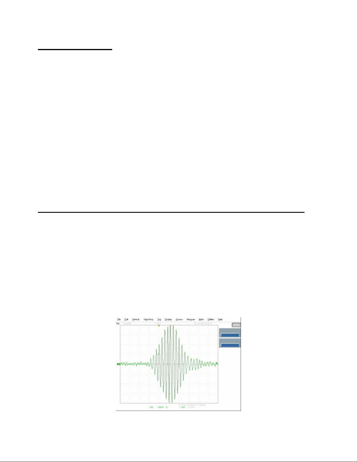
RF Spectrum of the AEVK-01 transmitter without an application. It also
provides the ability to measure individual sub-bands to confirm 500Mhz
minimum bandwidth.
The first step to utilize the RF Test Mode involves reloading firmware onto the
AEVK-01, since the default configuration is standard streaming mode. Please
refer to Tech Note 4001 for instructions on loading new firmware onto the
AEVK-01. When using the RF Test Mode, a special DIP switch connector,
provided separately, must be attached to the Aux Port on the AEVK-01 to
control different modes of the radio. The following table lists the DIP switch
positions on the external connector that alter the behavior of the AEVK-01:
Switch
#
ON
Position
OFF
position
Note: Once a change has been made to the DIP Switch, the AEVK-01 reset button
must be pressed for the change to become effective.
1 2 3 4 5 6 7 8
Disable
Freq1
Enable
Freq1
Disable
Freq2
Enable
Freq2
Disable
Freq3
Enable
Freq3
Disable
Freq4
Enable
Freq4
Disable
Freq5
Enable
Freq5
Video
Pseudo
Random
Symbols
Repeat
Same
Symbol
Continuous
mode
Burst
mode
~ 1
second
Switches 1-5 control the individual sub-bands, allowing for verification of each
band’s 500 MHz bandwidth compliance. Switch 6 activates the embedded
sample video data to be transmitted. Switch 7 changes the mode between
pseudo-random symbols (normal mode) to a mode which repeats a single
symbol. Switch 8 allows an override of the receiver-sense function, allowing a
continuous streaming of the video data even when a receiver is not present.
Two sets of files are included in the AEVK-01 CD in the RF Test Mode firmware
folder, one that programs the RF control, and one that configures the baseband
modem.
FPGA Digital RF Digital BB
MCS files Mogul.mcs
fcc_top_0.mcs
fcc_top_1.mcs
BIT files Mogul.bit Fcc_top.bit
12
This document contains proprietary information subject to the terms and
conditions of General Atomics Aspen Developers Program Nondisclosure
Agreement
Page 13

The MCS file loads the devices’ EEPROM, which maintains that version of
firmware even through power cycling. BIT files are also included that load into
a devices’ RAM, allowing mode changes that remain in effect until the device is
powered off.
Questions
Answers to most question regarding the setup and operation of your AEVK-01
can be found on GA’s UWB support website:
http://photonics.ga.com/uwb/support
Questions not addressed here can be submitted to uwbsupport@ga.com
contact your sales representative.
or
13
This document contains proprietary information subject to the terms and
conditions of General Atomics Aspen Developers Program Nondisclosure
Agreement
Page 14
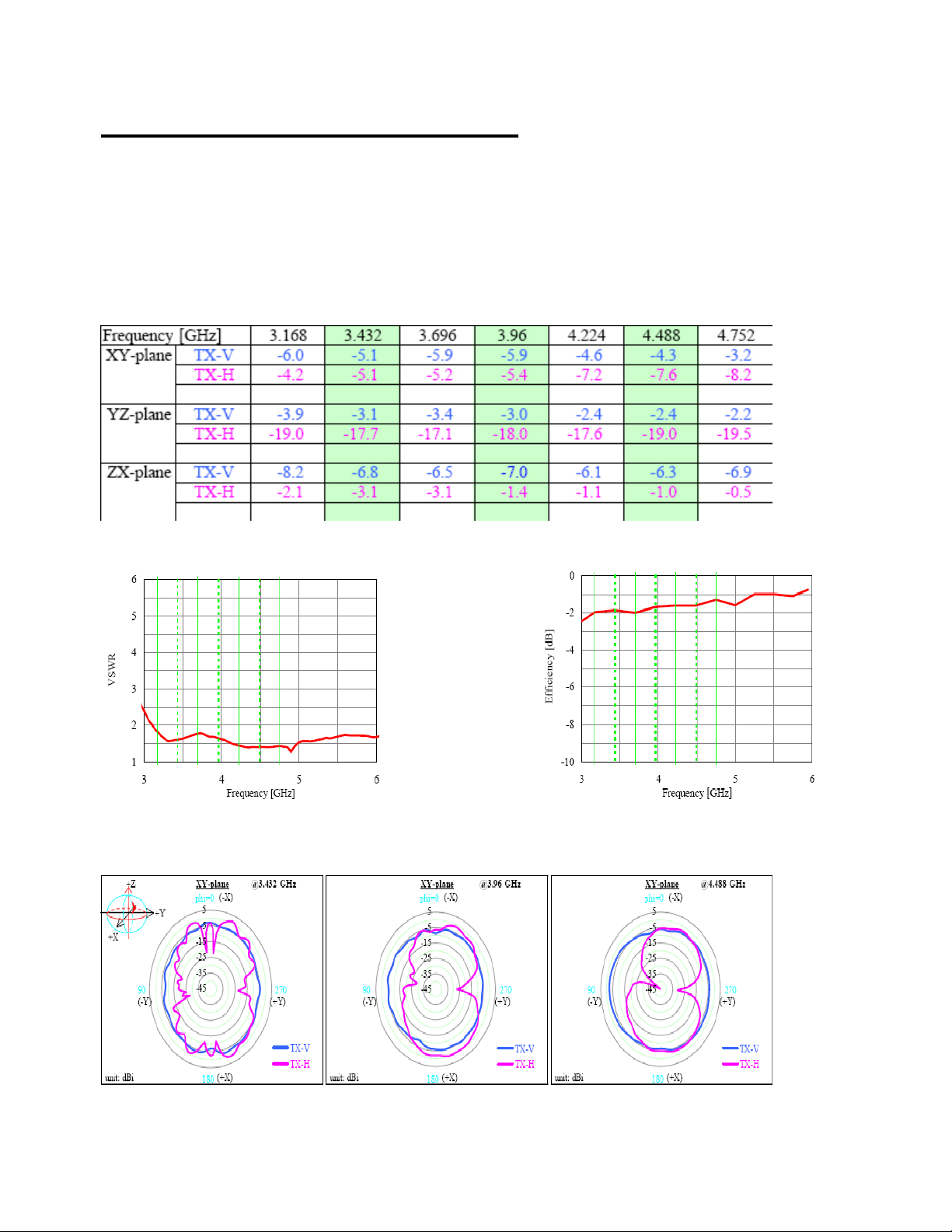
Antenna Characteristics
This section covers the antenna characteristic that is used in the AEVK-01 kit.
The antenna is roughly omni in nature, and provides nearly uniform gain over
the frequency range of operation. System performance can be affected by
factors such as room configuration, construction, and antenna pointing.
Information on optimal performance considerations can be found on the
General Atomics UWB Customer Support website.
Average gain data (dBi)
VSWR Data Efficiency Data
14
This document contains proprietary information subject to the terms and
conditions of General Atomics Aspen Developers Program Nondisclosure
Agreement
Page 15

XY Radiation Pattern
YZ Radiation Pattern
ZX Radiation Pattern
15
This document contains proprietary information subject to the terms and
conditions of General Atomics Aspen Developers Program Nondisclosure
Agreement
 Loading...