

Page 1

TM
Residential Fire Protection Pump & Tank System
For NFPA 13D Applications
Installation, Operation & Maintenance Manual
Installation Date: Contractor:
Person Installing:
For Emergency Service Call:
Version 1.5
4-24-19
Page 2

Table of Contents
Section 1 - Safety & Warnings
1.1 - Safety Guidelines
1.2 - Unpacking
1.3 - General Saf et y Information
1.4 - Water Tank Safety Information
1.5 - Water Tank Lid Safety Tie Down Instructions
Section 2 - System Description
Section 3 - Installation Instructions
3.1 - Initial Inspection
3.2 - Rigging & Moving
3.3 - Location & Installation
3.4 - Piping
3.5 - Wiring
3.6 - Start-Up & Maintenance
Section 4 - System Testing & Training
Section 5 - Start-Up Checklist
Section 6 - Filling the System
Section 7 - Water Inlet Connection Diagrams
Section 8 - Warranty Policy
IMPORTANT: ALL INFORMATION SUBJECT TO CHANGE WITHOUT NOTICE.
Consult factory for the most up to date version of this manual.
- Please take the time to complete the forms on the front and back of this manual.
- Additional information may be found attached to the back of this manual.
Page 3
Section 1 - Safety & Warnings
1.1 Safety Guidelines
This manual contains information that is very i m port ant to know and understand. This information i s provided for SAFETY
and to PREVENT EQUIPMENT PROBLEMS. To help rec ognize this information, observe the following symbols.
Danger indicates an imminently hazardous situation which, if not avoided, WILL
DANGER
result in death or serious injury.
WARNING
CAUTION
Warning indicates a potentially hazardous situation which, if not avoided COULD
result in death or serious injury.
Caution indicates a potentially hazardous situation which, if not avoided, MAY result
in minor or moderate injury.
NOTICE
Notice indicates important information, t hat if not followed may cause damage to
equipment.
1.2 Unpacking
After unpacking the unit, carefully inspect for any damage that may have occurred during transit, Mak e sure to tighten
fittings, bolts, etc., before putting unit into service.
Do not operate unit if damaged during shipping, handling or use.
1.3 General Safety Information
1. Read all manuals included with this product carefully. Be thoroughly familiar with the controls and the
proper use of the equipment
2. Follow all local electrical and safety codes as well a s National Electrical Codes (NEC), Occupational
Safety and Health Act (OSHA), and National Fire P rotection Association (NFPA)
3. Only persons familiar with these rules of safe operatio n should be allowed to use the equipment.
4. Keep visitors away and NEVER allow children in the work area.
5. Wear safety glasses and use hearing protection when operating the unit.
6. Do not stand on or use the unit as a handhold.
7. Periodic inspection and test of this equipment is required. Consult your installer and local codes to meet
all requirements.
8. Check all fasteners at frequent intervals for proper tightness.
Page 4
Section 1 - Safety & Warnings
1.3 General Safety Information (Continued)
- Motors, Electrical Equipment and Contro l s ca n cause electrical arcs that will
WARNING
NOTICE
WARNING
1.4 Water Tank Safety Information
- Confined spaces must be considered hazardous. DO NOT enter tank at any time.
- Fill tank with water and hold for at least 5 hours PRIOR to use to identify leakage through unsecured fittings, shipping
damage or manufacturing defects. The manufacturer's warranty of this tank is void unless upon installation of the tank, the
tank is water pre-tested as a final test of suitability. Manufacturer is not responsible for loss of materials. See manufacturer's
limited warranty.
- DO NOT use for vacuum or pressure applications. Tank is suppli ed properly vented.
- Continuous operating temperatures above 140°F (60 °C) are NOT RECOMMENDED. Consult factory for operating
temperature above 100°F (38°C).
- Protect tanks from impact (especially sharp blows).
- Installation sites for tanks should be on a reinforced concret e pad. Soil sites for smaller tanks must be solid, stable and
compacted. All sites must be level, flat, free of rocks or other objects, and above known flood plains.
- Weight of strainers, valves, hose or pipe must not be carried by the tank outlets.
- User is responsible for determining compatibility of chemicals with tank and fitting materials. TESTING IS
RECOMMENDED. Tank should not be used for anything other than water.
- Use expansion joints or other flexible connection methods at all tank fittings to prevent damage from differential expansion and contraction of piping and tank. The use of rigid piping or the failure to provide for the expansion of the tank will
void all warranties.
- Observe all local, state and federal codes.
ignite a flammable gas or vapor.
- Never operate or repair in or near a flammable gas or vapor.
- Never store flammable liquids or gases in the vicinity of the system.
- For up to date fire protection informatio n pl ease consult the National Fire
Protection Association at www.nfpa.org.
Use a backup wrench when adjusting the water inlet pipi ng on the tank. There
is a float and shutoff valve connected to the inlet bulk head. Moving the inlet
bulkhead without the use of a backup wrench will loosen the float and valve
out of position. This will cause possible overflow of t he tank.
Page 5
Section 1 - Safety & Warnings
1.5 Water Tank Lid Safety Screw Instructions
Tank Lid
Safety Screws
Float Valve Assembly
- For safety reasons the tank lid is secured with safety screws.
Do not remove safety screws in the tank lid. If screws are removed for service reasons, they must be reinstalled when work is completed.
Page 6

Section 2 - System Description
This unit is a pump & tank package specifically designed for installation in residential / light commercial installations.
This system is used on the sprinkler system to supplement, or provide, from the tank,
NOTICE
The tank holds a given volume of water to be supplied to the sprinklers if they activate. The pump will turn on if the
pressure, sensed by the pressure switch, drops to the lower set point (consult QC sheet). As long as the water pressure
in the fire sprinkler system is above the lower set point the pump will not turn on.
NOTICE
This system was custom designed to meet given flow rates and set to activate at given pressures. Consult the
design limit sheet or pump curve to verify the design criteria. If the design limit sheet has not been completed,
contact your installer for the information.
a sufficient volume of water to meet the system design limits (at the time of
installation). If Code changes are made, you should consult your installer to ensure
revisions are incorporated into your system as the code changes take effect.
The optional flow switch is designed to be tied into the alarm and control system. It
incorporates an adjustable retard (time delay) to avoid false alarms. The installing
technician should tie the flow switch, if installed, into the system as required by the
AHJ or the system designer during initial install ation.
Section 3 - Installation Instructions
3.1 Initial Inspection
When the equipment and accessories are received, they should be immediately inspected for shortages and damage. If
the equipment has been damaged in shipment or shortages are noticed, immediately notify the carrier and file a claim. If
hidden damage to the residential pump system is suspected, it is recommended that the system be filled with water as a
leak check prior to rigging and/or final placement.
3.2 Rigging & Moving
The exact method of handling and setting the residential pump system depends on the available equipment, the size of the
unit, its final location and other variables. It is the rigger's or mover's responsibility to determine the specific method of
safely handling each unit.
UNDER NO CIRCUMSTANCES SHOULD THE PIPING BE USED IN LIFTING OR
CAUTION
MOVING THE SYSTEMS.
3.3 Location & Installation
Residential pump systems must be mounted indoors unless specifically ordered for special locations.
CAUTION
THE SYSTEM MUST BE INSTALLED LEVEL.
CAUTION
THE SYSTEM MUST BE KEPT ABOVE FREEZING (32º F) AT ALL TIMES.
THE ENTIRE SURFACE OF THE TANK BOTTOM MUST BE IN CONTACT WITH
CAUTION
THE FLOOR SURFACE. NEVER ELEVATE THE TANK.
Page 7

Section 3 - Installation Instructions
Pump Assembly Components:
NOTICE
The H2hOme pump assembly can be removed for t ransporting and servicing the unit.
Pump Assembly Removal Instructions:
1 2
Remove the bolts on both sides of base plate. Loosen clamps on cam fitting & disconnect hose.
Page 8

Section 3 - Installation Instructions
3
Slide the right side of pump assembly out first using the handles on the sides of the base plate.
Pump Assembly Reinstallation Instructions:
4
Continue to pull the pump assembly out by the base
plate handles & disconnect the test hose.
2 1
Using the handles on base, slide the left side of pump assembly into the tank opening & connect test hose.
3
Install the hose & lock the clamps on cam fitting. Install the bolts on both sides of base plate.
Position the pump assembly so the slots in the base
line up with the nuts on both sides.
4
Page 9

1”or 1½”
Section 3 - Installation Instructions
When removing / installing
NOTICE
panel, the power cords to the pump and pressure switch will need
to be disconnected / reconnected.
the pump assembly on units
with the optional control
Pump Cord
Pressure Switch Cord
3.4 Piping
Riser Installation Instructions:
Thread the riser into manifold and tighten until riser is in an upright position.
Optional Flow Switch Connection Plug:
If customer does not require the use of a flow switch,
the port can be plugged with the supplied flow switch
port plug provided by General Air Products. It is a
solvent weld connection, CPVC approved solvent
cement will be needed to connect the two pieces to
each other. Add solvent cement to the inside of the tee
and the outside of the plug.
All fluid piping practices should be in accordance with local codes. The systems are
NOTICE
constructed using non-ferrous piping. Whenever components made from different
material are piped in a system, use dielectric isolatio n of the material to help preven t
galvanic corrosion. All threaded pipe connections must be sealed.
Home Riser
Connection
Correct sizing of pipe is critical to assure proper operation.
of the piping system attached to this system.
is ready to leak test. Pressurize the system with water and check around each connection and joint for leaks.
Do not use the system pump to fill the fire sy stem with the initial fill of water. Us e the domestic water so urce to prime the
system and tank.
The fire protection contractor is responsible for calculation
Once all piping and accessory installation has been completed, the system
Page 10

When installing Y-Strainer piping
Section 3 - Installation Instructions
3.4 Piping (Cont’d)
Autofill Y-Strainer Instructions:
manifold DO NOT use pipe dope
on any connection point leading
up to the autofill bulkhead.
CAUTION
Debris, pipe sealant, and other contaminants e ntering the a uto -fill valve will cause th e
valve to malfunction. Flush at least 3 gallons of water through the fill line prior to
connection to the H2Home. This will hel p ensure debris does not enter the auto-fill
valve.
Overflow Piping Instructions:
Minimize vertical piping to overflow bulkhead to ensure that over flow does not seep out of tank lid .
Page 11

Ground
120 V Hot
Neutral
Section 3 - Installation Instructions
3.5 Wiring
WARNING
system (provided by others in the field). A ground screw is located inside the pressure switch housing. All grounding
and bonding must follow local and NEC codes for all equipment and controls.
Connecting Power To Standard Units :
The electrical installation should be in accordance with the National Electrical
Code and any local codes and regulations. Pumps have inherent thermal overload protection. Check nameplate voltage to be sure it is in agreement with the
power supplied. An approved disconnect switch must be installed for this
Inside Pressure Switch:
120 V Hot
Power Input
Connecting Power To Units With Optional Control Panel:
Inside Control Panel:
120 V Hot
Ground
Optional Alarm Connection:
3.6 Start-Up & Maintenance
NOTICE
Connect alarm cord to socket and screw to tighten.
When hydro testing the system, the pump must be isolated using the ball valve
supplied, on the pump discharge piping, prior t o hydro testing.
Page 12

Section 4 - System Testing & Training
Periodic testing of the system is required. For information on the testing schedule,
NOTICE
consult your installation company.
For Testing Requirements and Training Inf ormation, consult your installation company.
The test connection between the pump discharge and the top of the tank is for testing
WARNING
the pump circulation. Never connect the discharge test connection to the pump inlet.
This will cause excessive heat and damage to the system.
Section 5 - Start-Up Checklist
H2hOme System Start-up Checklist:
1.) Check that motor is securely fastened to the base plate.
2.) Connect sprinkler piping to customer connection on pump piping.
Note: customer piping must be independently supported and not impart stress to unit piping
3.) Wire power to system. (see section 3.5)
4.) Ensure correct voltage is applied. See product label for voltage of system.
5.) Open pump suction valve and system valve. Close the test/recirculation valve. (see section 3.1)
6.) Fill the tank with water. (see section 7)
7.) Vent the pump of all air. (see section 6)
8.) Check the tank and piping connections for leaks.
9.) Test unit in accordance with local procedures.
10.) Verify the setting on the pressure switch is correct.
11.) Secure all valves.
12.) Post warning signs as required by local codes.
Page 13

bulkhead.
Section 6 - Filling the System
When first filling up the system, ensure that all of the air is bled out of the pump and piping. The pump is supplied with a
hex bolt on the housing (see below) that allows the pump casing to be vented. Loosen the hex bolt to allow air to escape.
Once the pump casing is filled with water, tighten the hex bolt. If the pump does not have a hex bolt, open the test valve
on the pump discharge pipe.
NOTICE
Stainless Steel Pump
Fill system using domestic water supply. Do not us e pump and tank to fill system.
Hex Bolt
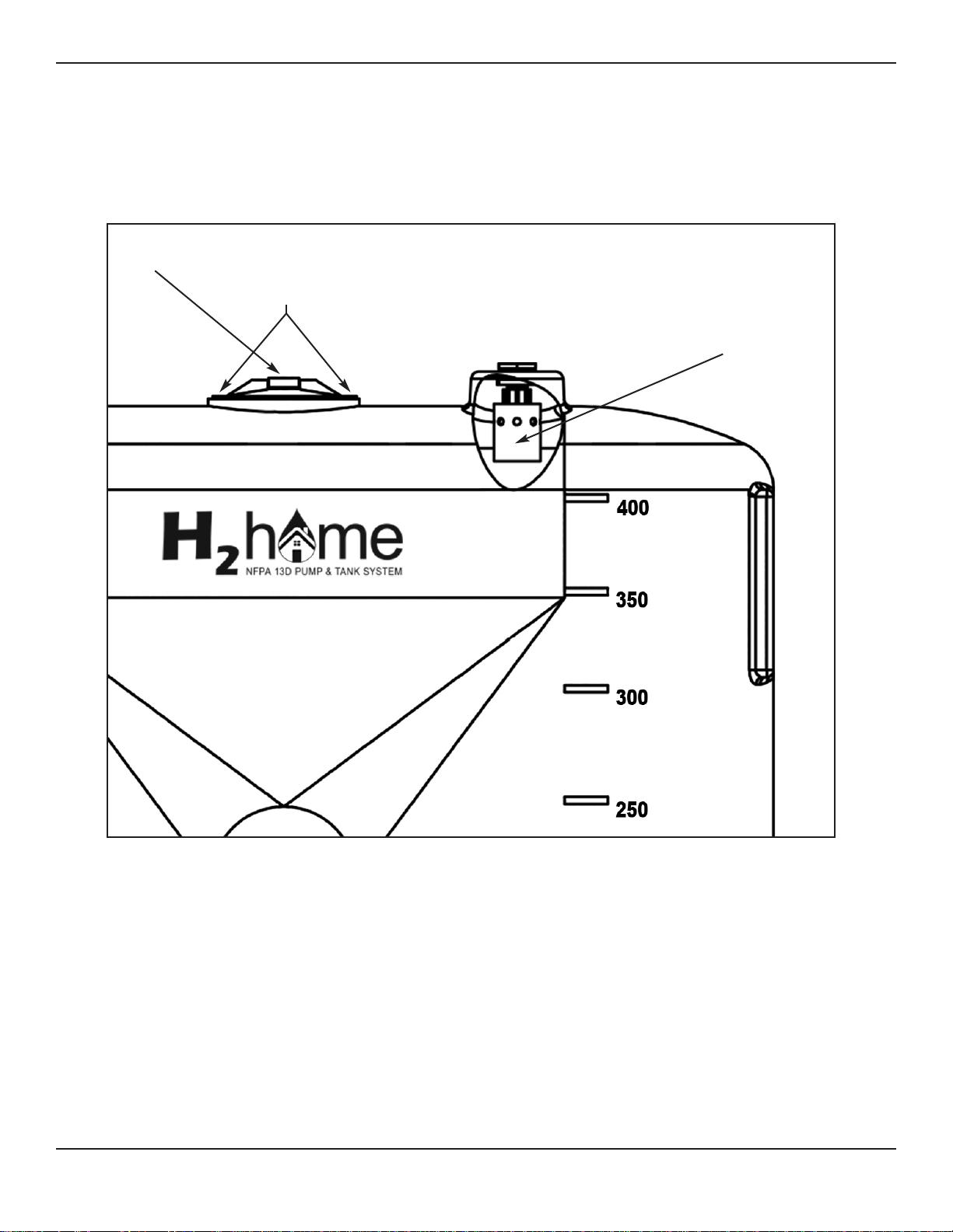
Section 7 - Water Inlet Connection Diagram
H2hOme System Water Inlet Connection Diagram
Top Mount Inlet Connection
If using copper piping, all soldering must be done away from the plastic tank and
WARNING
Float Valve Assembly
Page 14

Section 8 - Warranty Policy
GENERAL PROVISIONS & LIMITATIONS
General Air Products, Inc. (the "Com pany" ) warrant s to e ach orig inal purchaser ("Purchaser") of its new products from the Company
or its Authorized Distributor that suc h products are, at the time of
delivery to the Purchaser, made with good materials and workmanship. No warranty is made with respect to:
1. Any product, which has been repaired or altered in such
a way, in the Companies judgment, as to affect the
product adversely.
2. Any product, which has, in the Companies judgment been
subjected to negligence, accident, improper storage,
improper installation or application.
3. Any product, which has not been operated or maintained
in accordance with the recommendations of the
Company.
4. Components or accessories manufac tured, warranted
and serviced by others.
5. Any reconditioned or prior owned product.
Claims for items described in 4. above should be submitted directly
to the manufacturer.
WARRANTY PERIOD
The Company's obligation under this W arranty is limited to repair
or, at its option, replacing during normal business hours at the
designated facility of the Com pany, any part that in its judgment
proved not to be as warranted within the applicable Warranty
Period as follows.
COMPONENTS
All non-consumable components are warranted for 12 months from
the date of purchase. Consumables are not covered under
warranty. The unit must have been installed by either a factory
authorized distributor or agent in accordance with the factory
recommendations taking into account all other loc al site conditions
not originally noted to the factory. T he unit must be operated and
maintained in accordance with the Fact ory recommendations and
original design conditions. Failure to provide such proof of the
above may void warranty.
LABOR TRANSPORTATION & INSPECTION
The Company will repair or replace any product or part thereof
which in the Companies judgment is proved t o be not as warranted. Labor costs are not covered under warranty.
All costs of transportation of prod uct, labor or parts claimed not to
be as warranted and, of repaired or replaced parts to or from
factory shall be borne by purchaser. The Company may require the
return of any part claimed not to be as warranted to one of its
facilities as designated by the Company, t ransportati on prepaid by
Purchaser, to establish a claim under t his warranty.
Replacement parts provided under the ter ms of the warranty are
warranted for the remainder of the W arranty Period of t he product
upon which installed to the same extent as if such parts were
original components.
DISCLAIMER
THE FOREGOING WARRANTY IS EXCLUSIVE AND IT IS
EXPRESSLY AGREED THAT, EXCEPT AS TO TITLE, THE
COMPANY MAKES NO OTHER WARRANTIES, EXPRESSED
OR IMPLIED OR STATUTORY, INCLUDING ANY IMPLIED
WARRANTY OR MERCHANTABILITY.
THE REMEDY PROVIDED UNDER THIS WARRANTY SHALL BE
THE SOLE, EXCLUSIVE AND ONLY REMEDY AVAILABLE TO
THE PURCHASER AND IN NO CASE SHALL THE COMPANY BE
SUBJECT TO ANY OTHER OBLIGATIONS OR LIABILITIES.
UNDER NO CIRCUMSTANCES SHALL THE COMPANY BE
LIABLE FOR SPECIAL, INDIRECT, INCIDENTAL OR
CONSEQUENTIAL DAMAGES, EXPENSES, LOSSES OR
DELAYS HOWSOEVER CAUSED.
No statement, representation, agr eement, or understanding, oral
or written, made by any agent, distributor, representative or
employee of the Company which is not conta ined in this Warr anty
will be binding upon the company unless made in writing and
executed by an officer of the Company.
This warranty shall not be effective as to an y claim which is not
presented within 30 days after the date upon which the product is
claimed not to have been as warranted. Any act ion for breach of
this warranty must be commenced within one year after the date
upon which the cause of action occurred.
Any adjustment made pursuant to this warranty shall not be
construed as an admission by the Company t hat any product was
not as warranted.
PROMPT DISPOSITION & RETURNS POLICY
The Company will make a good faith effort for prom pt corr ection or
other adjustment with respect to any produc t, which proves to be
defective within the warranty per iod. Bef ore returni ng any product,
write or call the distributor, agent or authorized company from
which the product was purchased, describing defect and giving
date and number of original invoice, a well as proof of Factory supplied consumables and proof of sc heduled maint enance. No products will be accepted for return without the Company issuing a
“Returned Goods Authorization” (RGA) to the Purchaser and
unless accompanied by a properly authoriz ed RGA request form
initiated by the Purchaser. Return freight must be prepaid and each
returned product must have the RG A number clearly marked on
the product. Title and risk of loss pass to buyer upon delivery to the
common carrier.
PRODUCT SUITABILITY
Many States, Localities and Countri es hav e c odes a nd regulations
governing sales, construction, installation, and/or use of products
for certain purposes, which may vary from those in neighboring
areas. While General Air Product s, Inc. attempts t o assure that its
products comply with such codes, it cannot guarantee compliance,
and cannot be responsible for how the product is installed or used?
Before purchase and use of a product, plea se review the product
application, and national and local c odes and regulations, and be
sure that the product, installati on, and use will comply with them.
REV:4/22/11
Page 15

Pressure Switch Setting:
On
Off
Flow Rate:
System Pressure:
TM
Design Limits Information
Piping
Tested By
Date
Inspected By
Service Sheet
Date
Assembly
Tested By
Date
Inspected By
Date
 Loading...