

Page 1
GENERAI_A_ire
INSTALLER: PLEASE FILL OUT AND MAIL GUARANTEE CARD AFTER INSTALLATION
IS COMPLETE. LEAVE INSTALLATION INSTRUCTIONS WITH HOME OWNER
PRECAUTION: The installer should be an experienced service technician. Disconnect electrical power before beginning installation. Do not install where
temperatures fall below 32 degrees F or where plenum temperatures exceed 200 degrees F. When wiring into a multi-speed blower circuit see Step 7D.
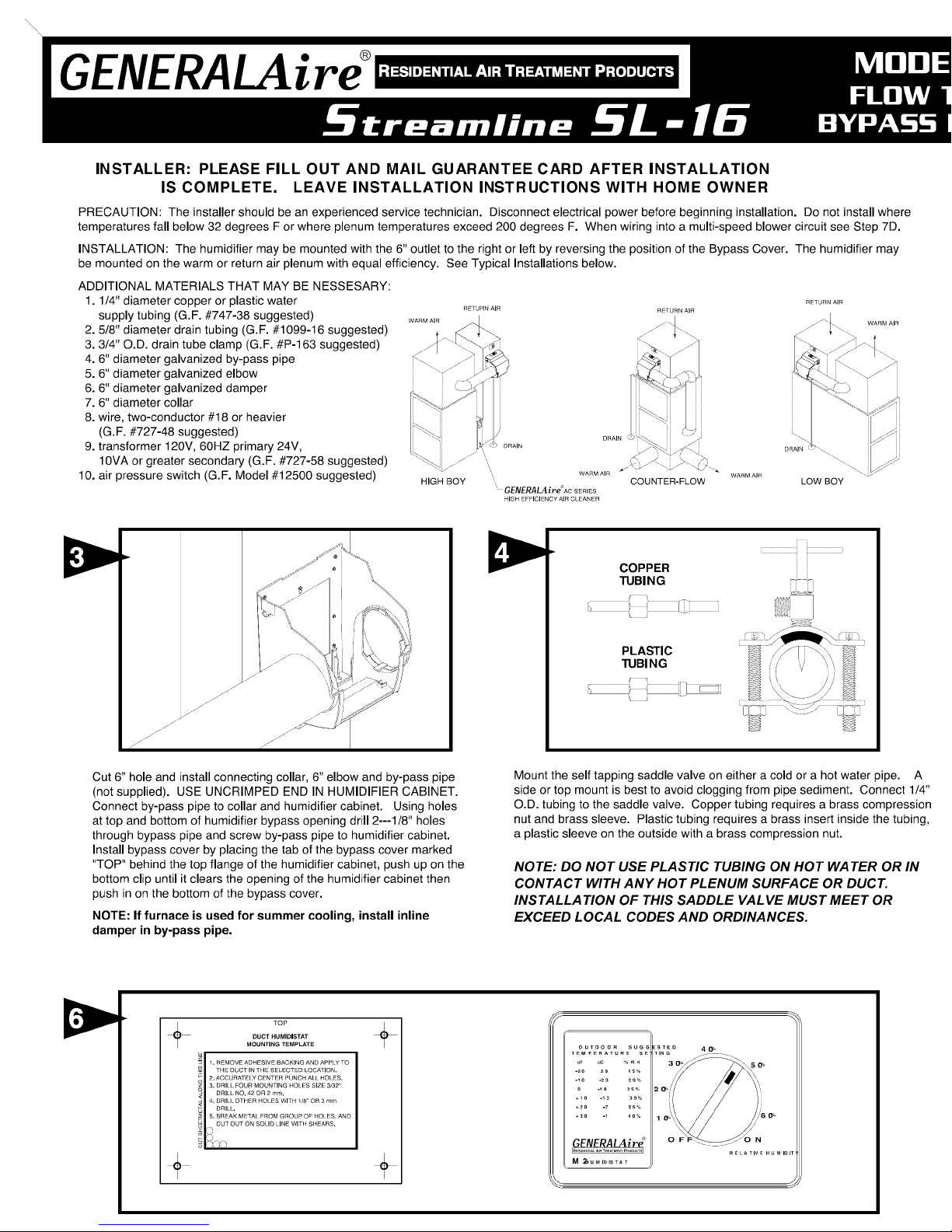
INSTALLATION: The humidifier may be mounted with the 6" outlet to the right or left by reversing the position of the Bypass Cover. The humidifier may
be mounted on the warm or return air plenum with equal efficiency. See Typical Installations below.
ADDITIONAL MATERIALS THAT MAY BE NESSESARY:
1.1/4" diameter copper or plastic water
supply tubing (G.F. #747-38 suggested)
2. 5/8" diameter drain tubing (G.F. #1099-16 suggested)
3. 3/4" O.D. drain tube clamp (G.F. #P-163 suggested)
4. 6" diameter galvanized by-pass pipe
5. 6" diameter galvanized elbow
6. 6" diameter galvanized damper
7. 6" diameter collar
8. wire, two-conductor #18 or heavier
(G.F. #727-48 suggested)
9. transformer 120V, 60HZ primary 24V,
1OVA or greater secondary (G.F. #727-58 suggested)
10. air pressure switch (G.F. Model #12500 suggested)
HIGH BOY
',,,
", WARMAIR
' GENERALAIre"ACSERIES
HIGH EFFICIENCYAIRCLEANER
COUNTER-FLOW LOW BOY
WARM AIR
Cut 6" hole and install connecting collar, 6" elbow and by-pass pipe
(not supplied). USE UNCRIMPED END IN HUMIDIFIER CABINET.
Connect by-pass pipe to collar and humidifier cabinet. Using holes
at top and bottom of humidifier bypass opening drill 2---1/8" holes
through bypass pipe and screw by-pass pipe to humidifier cabinet.
Install bypass cover by placing the tab of the bypass cover marked
"TOP" behind the top flange of the humidifier cabinet, push up on the
bottom clip until it clears the opening of the humidifier cabinet then
push in on the bottom of the bypass cover.
NOTE: If furnace is used for summer cooling, install inline
damper in by-pass pipe.
COPPER
TUBING
PLASTIC
TUBING
Mount the self tapping saddle valve on either a cold or a hot water pipe. A
side or top mount is best to avoid clogging from pipe sediment. Connect 1/4"
O.D. tubing to the saddle valve. Copper tubing requires a brass compression
nut and brass sleeve. Plastic tubing requires a brass insert inside the tubing,
a plastic sleeve on the outside with a brass compression nut.
NOTE: DO NOT USE PLASTIC TUBING ON HOT WATER OR IN
CONTACT WITH ANY HOT PLENUM SURFACE OR DUCT.
INSTALLATION OF THIS SADDLE VALVE MUST MEET OR
EXCEED LOCAL CODES AND ORDINANCES.
DUCT HUMIDISTAT
TOP
MOUNTING TEMPLATE
1, REMOVE ADHESIVE BACKING AND APPLY TO
THE DUCT IN THE SELECTED LOCATION,
2, ACCU RATE|Y CENTER PUNCH ALL HOLES,
3. DRILl FOUR MOUNTING HOLES SIZE 3/32",
DRILL NO, 42 OR 2 ram,
4. DRILl OTHER HOtES WITH 118"OR 3 mm
DRILL,
5, BREAK METAL FROM GROUP OF HOLES AND
CUT OUT ON SOLID LINE WITH SHEARS.
+
+
OUTDOOR SUGC
TEMPERATURE SE
oF oC % R H
-20 29 IS°/o
0 -lS 2S_
+I0 -12 30_
*2O -7 3S%
+3O -I 40_
GENERALAire_
E ]
M _UMIDISTAT
\ /
Page 2
+ +
Select location on vertical surface of warm or return air plenum for
mounting humidifier and tape mounting template. Make sure the
template is level. Do not install humidifier or 6" bypass pipe where the
blanked off ends of a cooling coil will restrict air flow to the humidifier.
Extend horizontal centerline from template to the adjacent plenum.
Scribe 6" circle 10" to 15"from side of humidifier, on cabinet centerline.
SADDLE VALVE INSTALLATION INSTRUCTIONS
Copper Pipe
1. Retract piercing pin into valve body by turning handle counterclockwise.
2. Screw valve body into upper bracket and tighten.
3. Place rubber gasket over piercing pin.
4. Assemble saddle valve over copper pipe using enclosed screws, nuts
and lower bracket.
5. Tighten screws evenly and firmly. Brackets should be parallel.
6. Complete compression connection to saddle valve outlet.
7. Turn handle clockwise to pierce tubing and close saddle valve.
8. Turn handle counterclockwise to open saddle valve, leave open for
several seconds to flush dirt from pipe and tubing.
Steel, Brass or Hard Plastic Pipe
1. Shut off water supply and drain pipe.
2. Turn handle clockwise to expose piercing pin and close saddle valve.
3. Place rubber gasket over piercing pin.
4. Drill 1/8" hole in pipe using a hand crank drill to avoid shock hazard.
5. Assemble saddle valve over steel, brass or hard plastic pipe using
enclosed screws, nuts and lower bracket.
6. Tighten screws evenly and firmly. Brackets should be parallel.
7. Complete compression connection to saddle valve outlet.
8. Turn handle counterclockwise to open saddle valve, leave open for
several seconds to flush dirt from pipe and tubing.
Threaded Pipe Fittings
1. Turn handle clockwise to expose piercing pin and close saddle valve.
2. Seal valve body threads using pipe tape or sealant.
3. Install valve into 1/8" NPT fitting.
4. Complete compression connection to saddle valve outlet.
5. Turn handle counterclockwise to open saddle valve, leave open for
several seconds to flush dirt from pipe and tubing.
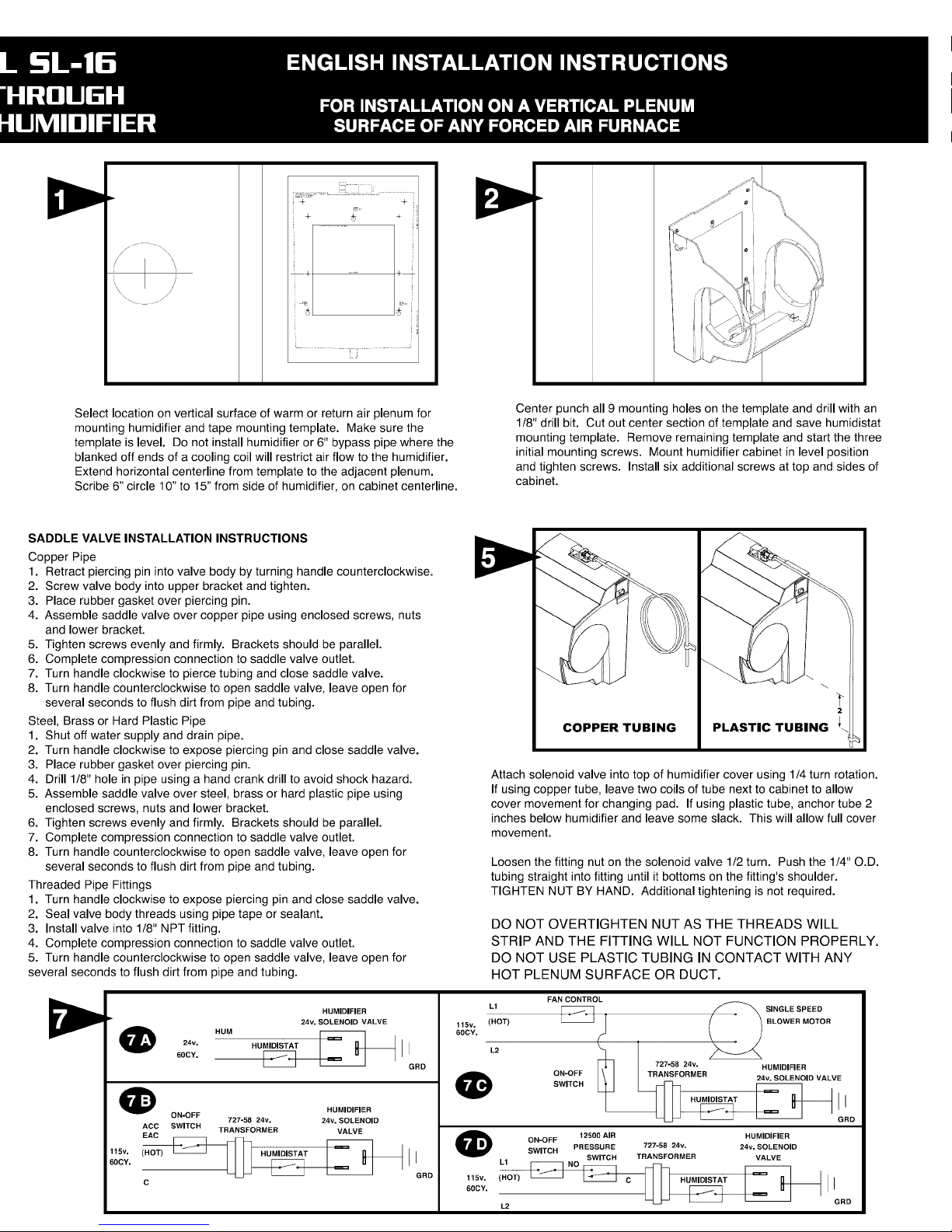
HUMIDIFIER
24v. SOLENOID VALVE
24v. HU I
60CY.
_1 ON-OFF HUMIDIFIER
ACC SWITCH TRANSFORMER VALVE
EAC
727-58 24v. 24v. SOLENOID
GRD
50cv.11sv"(HOT)_ll
C
GRD
Center punch all 9 mounting holes on the template and drill with an
1/8" drill bit. Cut out center section of template and save humidistat
mounting template. Remove remaining template and start the three
initial mounting screws. Mount humidifier cabinet in level position
and tighten screws. Install six additional screws at top and sides of
cabinet.
COPPER TUBING PLASTIC TUBING
Attach solenoid valve into top of humidifier cover using 1/4 turn rotation.
If using copper tube, leave two coils of tube next to cabinet to allow
cover movement for changing pad. If using plastic tube, anchor tube 2
inches below humidifier and leave some slack. This will allow full cover
movement.
Loosen the fitting nut on the solenoid valve 1/2 turn. Push the 1/4" O.D.
tubing straight into fitting until it bottoms on the fitting's shoulder.
TIGHTEN NUT BY HAND. Additional tightening is not required.
DO NOT OVERTIGHTEN NUT AS THE THREADS WILL
STRIP AND THE FITTING WILL NOT FUNCTION PROPERLY.
DO NOT USE PLASTIC TUBING IN CONTACT WITH ANY
HOT PLENUM SURFACE OR DUCT.
L1
115v. (HOT)
60CY.
O
115v. (HOT)
60CY.
L2
FAN CONTROL
BLOWER MOTOR
727_8 24v. HUMIDIFIER
ON-OFF 24v. SOLENOID VALVE
SWITCH _
ON-OFF
SWITCH PRESSURE 727-58 24v. 24v. SOLENOID
L1
12500 AIR HUMIDIFIER
SWITCH TRANSFORMER VALVE
TRANSFORMER
__ IIORD
Page 3
GENERAI_Aire
INSTALLATEUR : VEUILLEZ REMPLIR ET POSTER LA CARTE DE GARANTIE UNE FOIS L'INSTALLATION
TERMINI_E. LAISSER LES DIRECTIVES D'INSTALLATION AU PROPRII_TAIRE DE LA MAISON.
PRE_CAUTION : L'installateur doit etre un technicien qualifie et experimente. Couper I'alimentation electrique avant de commencer I'installation. Ne pas installer
I'appareil dans un endroit o0 la temperature peut descendre sous 0 °C (32 °F) ou si la temperature du plenum depasse 93 °C (200 °F). Lors dIun branchement
& un circuit de ventilateur & plusieurs vitesses, voir I'etape 7D.
INSTALLATION : LIhumidificateur peut etre installe avec la sortie de 15 cm (6 po) &droite ou & gauche en inversant le couvercle de derivation. L'humidificateur
fournit le meme rendement, quIil soit installe sur un plenum dIair chaud ou sur un plenum de reprise d'air. Voir rinstallation typique ci-dessous.
MATE_RIAUX ADDITIONNELS POUVANT I_TRE REQUIS :
1. Tuyau d'alimentation en cuivre ou en plastique de 6 mm (1/4 po) (G.F. n°
747-38 suggere)
2. Tube de drain de 1,6 cm (5/8 po) de diametre (G.F. n° 1099-16 suggere)
3. Collier de tube de drain de 1,9 cm (3/4 po) de diametre exterieur (G.F. n°
P-163 suggere)
4. Tuyau de derivation galvanise de 15 cm (6 po)
5. Coude galvanise de 15 cm (6 po)
6. Registre galvanise de 15 cm (6 po)
7. Collier de 15 cm (6 po)
8. Fil, deux conducteurs n° 18 ou plus Iourd (G.F. n° 727-48 suggere)
9. Transformateur 120 V, 60 Hz primaire 24 V, 10 VA ou plus grand
secondaire (G.F n° 727-58 suggere)
10. Commutateur de pression d'air (G.F. modele n° 12500 sugger6)
GENERALAIre'SERIES AC
HAUT RENDEMENT FILTRE A AIR
DRAIN
AIR CHAUD
.>..-"
.J
. y....--''
z
.J
...--"
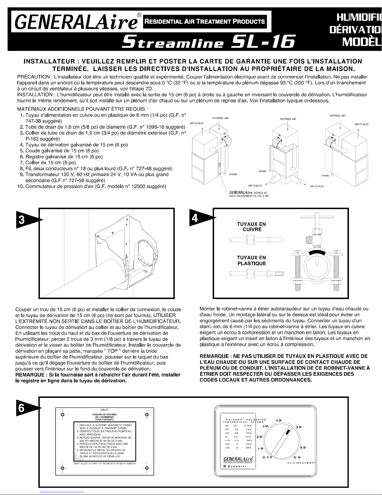
Couper un trou de 15 cm (6 po) et installer le collier de connexion, le coude
et le tuyau de derivation de 15 cm (6 po) (ne sont par fournis). UTILISER
L'EXTR#MITE_ NON SERTIE DANS LE BO/TIER DE L'HUMIDIFICATEUR.
Connecter le tuyau de derivation au collier et au boitier de IIhumidificateur.
En utilisant les trous du haut et du bas de I'ouverture de derivation de
IIhumidificateur, percer 2 trous de 3 mm (1/8 po) & travers le tuyau de
derivation et le visser au boTtier de I'humidificateur. Installer le couvercle de
derivation en pla?ant sa patte, marquee " TOP ,1derriere la bride
superieure du boftier de IIhumidificateur, pousser sur le taquet du bas
jusqu'A ce qu'il d6gage I'ouverture du boTtier de I'humidificateur, puis
pousser vers Ilinterieur sur le fond du couvercle de derivation.
REMARQUE : Si la fournaise sert b rafrafchir I'air durant I'_te, installer
le registre en ligne dans le tuyau de derivation.
TUYAUX EN
CUIVRE
TUYAUX EN
PLASTIQUE
Monter le robinet-vanne & etrier autotaraudeur sur un tuyau d'eau chaude ou
dIeau froide. Un montage lateral ou sur le dessus est ideal pour eviter un
engorgement cause par les sediments du tuyau. Connecter un tuyau d'un
diam. ext. de 6 mm (1/4 po) au robinet-vanne &etrier. Les tuyaux en cuivre
exigent un ecrou & compression et un manchon en laiton. Les tuyaux en
plastique exigent un insert en laiton & I'interieur des tuyaux et un manchon en
plastique & Ilexterieur avec un ecrou & compression.
REMARQUE : NE PAS UTILISER DE TUYAUX EN PLASTIQUE AVEC DE
L'EAU CHAUDE OU SUR UNE SURFACE DE CONTACT CHAUDE DE
PLleNUM OU DE CONDUIT. L'INSTALLATION DE CE ROBINET-VANNE ,_,
I_TRIER DOlT RESPECTER OU DI_PASSER LES EXIGENCES DES
CODES LOCAUX ET AUTRES ORDONNANCES.
GABARIT DE FIXATION
HAUT
DE L'HUMIDISTAT
POUR CONDUITS
1. ENLEVEZ LE SUPPORT ADHESIF ET POSEZ
SUR LE CONDUIT A L'ENDROIT CHOISI.
2, CENTREZ TOUS LES TROUS AU POINTEAU
AVEC PRECISION.
3. PERCEZ QUATRE TROUS DE MONTAGE DE
3/32 PO (MECHE N° 42 OU DE 2 ram),
4, PERCEZ LES AUTRES TROUS AVEC UNE
MECIIE DE 1/8 PO OU DE 3 ram,
5, DETACHEZ LE METAL DU GROUPE DE
) TROUS ET DECOUPEZ SUR LA LIGNE
._!,E......................
OUTDOOR SUGG
TEMPERATURE SE ¸
OF oC _ R H
-2O 29 15%
-10 -23 20_
0 -18 25_
+_O -12 30_
*20 -_ 3S_
+_0 -1 40_
GENERALAir_
J
Page 4

+
+
/,
//
Selectionner un emplacement sur la surface verticale d'un plenum d'air chaud ou
de retour d'air pour monter rhumidificateur et appliquer du ruban adh6sif sur la
matrice de montage. S'assurer que la matrice est & niveau. Ne pas installer
rhumidificateur ou le tuyau de derivation de 15 cm (6 po) & rendroit oQI'extremit6
de la plaque d'obturation d'un serpentin refroidisseur pourra restreindre le debit
d'air vers rhumidificateur. I_tendre la ligne horizontale centrale de la matrice vers
le pl6num adjacent. Tracer un cercle de 15 cm (6 po) entre 25 et 38 cm (10 & 15
po) du c6t6 de rhumidificateur, sur la ligne centrale du boftier.
INSTRUCTIONS D'INSTALLATION POUR LE ROBINET-VANNE A ETRIER
Tuyau en cuivre
1. R6tracter la tige & perforation clans le corps de la vanne en tournant la poignee dans le
sens horaire.
2. Visser le corps de la vanne dans le support superieur et serrer.
3. Placer le joint d'etanch6it6 en caoutchouc par-dessus la tige de perforation.
4. Assembler le robinet-vanne & _trier par-dessus le tuyau en cuivre en utilisant les vis ecrous
supports inferieurs fournis.
5. Serrer les vis de fa£on egale et ferme. Les supports doivent _tre paralleles.
6. Terminer la connexion de compression vers la sortie du robinet-vanne &etrier.
7. Tourner la poign_e dans le sens horaire pour percer le tuyau et fermer le robinet-vanne & et
8. Tourner la poignee dans le sens antihoraire pour ouvrir le robinet-vanne & etrier et le laisser
ouvert pendant quelques secondes pour evacuer la salete du tuyau et de la tuyauterie.
Tuyau en acier, en laiton ou en plastique dur.
1. Fermer ralimentation en eau et vidanger le tuyau.
2. Tourner la poignee dans le sens horaire pour exposer la tige de perforation et fermer le robinet-
vanne a.etrier.
3. Placer le joint d'_tancheite en caoutchouc par-dessus la tige de perforation.
4. Percer un trou de 3 mm (1/8 po) avec une perceuse & manivelle pour eviter les risques de choc
electrique.
5. Assembler le robinet-vanne & _trier par-dessus le tuyau en acier, laiton ou plastique dur en
utilisant les vis, ecrous et supports inferieurs fournis.
6. Serrer les vis de fa_on egale et ferme. Les supports doivent _tre paralleles.
7. Terminer la connexion de compression vers la sortie du robinet-vanne &#trier.
8. Tourner la poignee dans le sens antihoraire pour ouvrir le robinet-vanne & etrier et le laisser
ouvert pendant quelques secondes pour evacuer la salete du tuyau et de la tuyauterie.
Raccords de tuyau filetes
1. Tourner la poignee dans le sens horaire pour exposer la tige de perforation et fermer le robinet-
vanne & _trier.
2. Sceller le filetage du corps de la vanne avec un scellant ou du ruban adhesif.
3. Installer la vanne dans un raccord NPT de 3 mm (1/8 po).
4. Terminer la connexion de compression vers la sortie du robinet-vanne &etder.
5. Tourner la poignee dans le sens antihoraire pour ouvrir le robinet-vanne & etrier et le laisser
ouvert pendant quelques secondes pour evacuer la salete du tuyau et de la tuyauterie.
24 VOLTS DE LA VANNE
ELECTROMAGNI_TIQUE
24v. HU [
60CY.
TERRE
115v.
60CY.
Marquer au pointeau centreur les 9 trous de montage de la matrice
et percer avec un foret de 3 mm (1/8 po). Couper la section centrale
de la matrice et conserver la matrice de montage de rhumidistat.
Enlever la matrice restante et engager les trois vis du montage
initial. Monter le boftier de rhumidificateur & niveau et serrer les vis.
Installer six (6) vis supplementaires sur le dessus et sur les c6tes du
bo_tier.
TUYAUX EN CUIVRE
TUYAUX EN
PLASTIQUE
Fixer I'electrovalve au dessus de I'humidificateur en lui appliquant une rotation de
¼ de tour. Si des tuyaux de cuivre sont utilises, laisser deux serpentins de tuyau &
cSte de renceinte afin de permettre le mouvement du couvercle au moment de
remplacer le tampon. Si, par contre, le tuyau de plastique est utilise, ancrer ce
dernier & 5 cm (2 po) sous rhumidificateur tout en laissant un certain jeu. Ainsi, le
couvercle pourra _tre deplace librement.
Desserrer I'ecrou du raccord de I'electrovalve de 1/2tour. Enfoncer le tuyau de ¼
po de diam. ext. dans le raccord jusqu'& ce qu'il s'appuie sur son epaulement.
SERRER L'C:cROU ,&,LA MAIN. Un serrage supplementaire n'est pas requis.
NE PAS TROP SERRER L'ECROU; SES FILETS FOIRERAIENT, ET LE
RACCORD NE FONCTIONNERAIT PAS CORRECTEMENT. I_VITER
D'UTILISER TOUTE TUBULURE DE PLASTIQUE QUI ENTRERAIT EN
CONTACT AVEC UNE CHAMBRE DE DISTRIBUTION OU UNE CONDUITE
CHAUDES.
COMMANDE DE VENTILATEUR
L1
L2
[_ [ ///_ VENTILATUR UNE
BOUTON DE 24 VOLTS F_LECTROMAGNETIQUE
TRANSFORMATEUR 24 VOLTS DE LA VANNE
727-58
ACC BOUTON DE 24 VOLTS ELECTROMAGN_TIQUI:
EAC
115v . HUMIDISTAT
_OCY (ELECTRIFI I I
C
TRANSFORMATEUR 24 VOLTS DE LA VANNE
TERRE
_ _ TERRE
PRESSOSTAT 727-58
O BOUTON
115v. (F_LECTRI [
6OCY.
Li
D'AIR MODI_LE TRANSFORMATEUR
12508 DE 24 VOLTS ELECTROMAGN_TIQUE
-- TERRE
24 VOLTS DE LA VANNE
HUMIDISTAT
Page 5

MOUNTING ON THE RETURN AIR DUCT
Do not install the humidistat on the warm air duct.
1. Locate the humidistat at least 24" upstream of the humidifier or bypass on
the return air duct. Avoid areas of direct radiation like secondary heat
exchangers in the fan compartment•
2. Place template using level. Cut sensor hole as shown on template. Drill
four 3/32" holes as shown.
3. Remove the housing from the base by prying with a small screwdriver at
the notch in the side of the housing. Copy serial number, located on
housing back, onto the warranty registration.
4. Place the outer part of the foam gasket on the humidistat base and mount
the base with four screws. Low voltage wire may enter the humidistat
under the foam seal.
5. Connect wires to screw terminals on the control assembly as shown in
wiring diagram. Replace housing.
WALL MOUNTING INSTRUCTIONS
1. Chose a location for the humidistat about five feet above the floor on an
inside wall with average room temperature and humidity conditions.
2. Drill a small hole in the wall and run low voltage wiring to the location
chosen. Pull about 6" of wire through the hole. Plug the opening to
prevent drafts from affecting the humidistat operation•
3. Remove the housing from the base by prying with a small screwdriver at
the notch in the side of the housing. Copy serial number, located on
housing back, onto the warranty registration.
4. Mount the base horizontally over the wires using level. Attach directly to
the wall, using four screws provided.
5. Connect wires to screw terminals on the control assembly as shown in
wiring diagram. Replace housing.
Remove plastic bag from 990-13 evaporator pad, replace 16-4
distributor trough and close 16-2 cover. Turn on water supply and
check operation of humidifier• Set humidistat to a demand setting.
With the furnace off, the solenoid valve should be closed. Start the
furnace, the solenoid valve should open when the blower or burner
circuit is energized. Check flow of water through distributor trough
and evaporator pad. The solenoid valve will supply approximately 3.5
GPH of water at a line water pressure of 60 psi. Leave humidistat set
at the recommended setting.
Connect drain hose to 5/8" spout on humidifier cabinet using a 3/4" hose
clamp. Run 5/8" I.D. hose to suitable drain such as floor drain, sewer or
laundry sink. Be sure hose has continuous slope and is not kinked at any
point.
Your Humidifier is engineered to give helpful and trouble-free
humidification. For maximum efficiency the following cleaning
procedures should be carried out at the end of each heating season:
1. Turn off water supply and electrical power to humidifier.
2. Open humidifier cover, remove trough and evaporator
pad. If water line prevents cover opening disconnect water
line from solenoid valve• Clean excessive mineral deposits
from the distributor trough, humidifier cover and humidifier
DISTRIBUTOR
TROUGH
cabinet. A solution of 1/2 vinegar & 1/2 water will help
loosen mineral deposits.
3. If the evaporator pad has excessive mineral deposits,
replace with a new "990-13" evaporator pad. Install trough
and replace cover.
PART #990-13
EVAPORATOR
PAD
4. In heavy mineral areas or if the solenoid valve fails to
function disconnect the 1/4" water supply line from the
solenoid valve. Carefully pull the filter from the solenoid
valve. Clean the mineral deposits from all parts. If the
orificebeyond the filter is clogged, it may be opened by
inserting a small needle• Reinsert the filter into the solenoid
PART #16-1
HUMIDIFIER
CABINET
valve.
5. Reconnect the 1/4" water line to the solenoid valve if
necessary. Tighten nut by hand, additional tightening is not
required. DO NOT OVERTIGHTEN NUT AS THE
THREADS WILL STRIP AND THE FITTING WILL
NOT FUNCTION PROPERLY. Turn on the water
supply and check all points for leakage. The operation of
the unit may be checked by starting the furnace• The
humidifier operates only when the furnace blower is running
or the burner circuit is energized. The humidifier is now
ready for operation.
6. During the summer, turn off water supply and electrical
power to humidifier• Close inline air damper if installed. @ Copyright 2001,2002 GENERAL FILTERS, INC.
FORM NO. 16-18 (FILE 11068) REV. D
All Rights Reserved
PARTS NOT SHOWN:
800UST SADDLE VALVE
M-2 HUMIDISTAT ASSY.
\,4_"_ SOLENOID
•+j FITTING
Litho in U.S.A.
PART #16-2
COVER
PART #16-20
SOLENOID
VALVE ASS'Y
PART #16-12
NER
SCREEN
PART #P-236
HARDWARE
CUT TEMPLATE ALONG THIS LINE
Page 6

INSTRUCTIONSFORWIRING
PROVIDE SUFFICIENT WIRE TO ALLOW COVER TO
FULLY OPEN. Ground wire may be omitted in most
municipalities, CHECK WITH LOCAL AUTHORITIES
FOR COMPLIANCE.
FIG. 7A, 7B WlTH FURNACE CIRCUIT BOARD
On furnaces with output terminals HUM, ACC, or EAC check
output voltage to determine if terminals are 24V. or 115V.
NOTE: ALL WIRING SHOULD COMPLY WITH LOCAL
ELECTRICAL CODES.
The operating principle of the humidifier is based on the most efficient and economical means of evaporating water to
the air. The humidifier uses only five watts of electrical power during operation, less than the smallest household light
bulb. The heat necessary for evaporating water is produced by the furnace.
The water supply to the humidifier is controlled by the electric solenoid valve. The humidistat connected in series
with the solenoid provides low voltage control of the humidifier. The humidistat has a SPST switch and is designed for
wall mounting in the living area or surface mounting on the return air duct. RANGE: 10% to 60% RH ELECTICAL
RATING: 24 VAC / 60 Hz. DO NOT SET RELATIVE HUMIDITY TOO HIGH DURING COLD WEATHER. EXCESSIVE
HUMIDITY MAY CAUSE CONDENSATION ON WINDOWS OR IN WALLS. REFER TO RECOMMENDED
SETTINGS ON HUMIDISTAT.
Water flows through a strainer, is metered through an orifice to provide the proper amount of water, and is supplied to
the evaporator pad by the distributor trough. Approximately 200 CFM of air is by-passed from the warm air plenum
through the humidifier and returned to the cold air plenum. Moisture is evaporated to the air passing through the
evaporator pad.
Minerals are not blown into the air stream as occurs in atomizing humidifiers; they are left on the evaporator pad
where a high percentage is carried off with the waste water.
When the humidifier is installed and operating, no adjustments are necessary other than setting the control knob on
the humidistat to the desired level of humidification.
To turn the humidifier off, close water supply valve, switch electrical power off and turn humidistat off. If furnace is
used for summer cooling or ventilating close inline air damper if installed..
FIG. 7C WITH SINGLE SPEED BLOWER MOTOR
On furnaces with single speed blowers, mount a 24v. transformer on a
junction box with 115v. primary leads connected in parallel with the blower
circuit. Connect the leads from the 24v. solenoid valve to the terminal
screws on the transformer. Connect humidistat in series with the 24v.
circuit.
FIG. 7D WITH TWO SPEED BLOWER MOTOR
On furnaces with a two speed blower, the humidifier and a Model 12500
Air Pressure Switch may be wired from a continuous 115 volt power
source. Install the on/off switch and Air Pressure Switch in series with the
transformer primary on the hot or black wire. The Air Pressure Switch will
detect furnace operation and supply power to the humidifier accordingly.
AT
OUTSIDE RECOMMENDED
TEMPERATURE SETTING
-20OF -29°C
-10°F -23°C
0°F -18°C
+10°F -29°C
+20OF - 7oc
+30OF - 1oc
15%
20%
25%
30%
35%
40%
This humidifier, if properly registered by the return of the warranty
registration card to the manufacturer, is warranted to the
consumer against defects in materials and workmanship for a
period of one year from the date of installation. Evaporator pads,
sleeves or plates are not covered by this limited warranty or any
other warranties. Any other defective parts will be repaired without
charge except for removal, reinstallation and transportation costs.
To obtain repair service under this limited warranty, the consumer
must send the defective part or the complete humidifier to the
manufacturer.
THERE ARE NO EXPRESS WARRANTIES COVERING THIS
HUMIDIFIER OTHER THAN AS SET FORTH ABOVE, THE
IMPLIED WARRANTIES OF MERCHANTABILITY AND FITNESS
FOR A PARTICULAR PURPOSE ARE LIMITED IN DURATION
TO ONE YEAR. THE MANUFACTURER ASSUMES NO
LIABILITY IN CONNECTION WITH THE INSTALLATION OR USE
OF THIS PRODUCT, EXCEPT AS STATED IN THIS LIMITED
WARRANTY. THE MANUFACTURER WILL IN NO EVENT BE
LIABLE FOR INCIDENTAL OR CONSEQUENTIAL DAMAGES.
This limited warranty gives you specific legal rights, and you may
also have other rights which vary from state to state. Some states
do not allow either limitations on implied warranties, or exclusions
from incidental or consequential damages, so the above exclusion
and limitation may not apply to you.
Any questions pertaining to this limited warranty should be
addressed to the manufacturer. (U.S.A.: The manufacturer has
elected not to make available the informal dispute settlement
mechanism which is specified in the Magnuson-Moss Warranty
Act.)
GENERAL FILTERS, INC. CANADIAN GENERAL FILTERS,
43800 GRAND RIVER AVE. LTD. 39 CROCKFORD BLVD.
NOVI, MICHIGAN 48375-1115 SCARBOROUGH, ONTARIO
Visit our website at
MIR3B7
WWW. GENERA LA IRE. COM
OWNER REGISTER ONLINE AT WWW.GENERALAIRE.COM OR
FILL IN REGISTRATION
AND MAIL TO:
GENERAL FILTERS, INC.
43800 GRAND RIVER AVE.
NOVl, MICHIGAN 48375-1115
WAR RANTY REGISTRATION
MODEL SL-16 FLOW THROUGH BYPASS HUMIDIFIER
OWNER'S NAME
STREET ADDRESS
CITY STATE
DEALER'S NAME
STREET ADDRESS
CITY STATE
Humidifier Humidistat
SERIAL NUMBER SERIAL NUMBER
DATE OF INSTALLATION
POSTAL CODE
POSTAL CODE
CUT TEMPLATE ALONG THIS LINE
Page 7

INSTALLATION SUR LE CONDUIT DE REPRISE D'AIR
Ne pas installer rhumidistat sur le conduit d'air chaud.
1. Installez I'humidistat au moins 24 po en amont de I'humidificateur ou de la d6rivation
du conduit de reprise d'air. Evitez les zones de radiation directe, relies que les
echangeurs de chaleur secondaires darts le compartiment du ventilateur.
2. Orientez le gabarit au moyen d'un niveau. Decoupez I'orifice du capteur comme le
gabarit le montre. Percez quatre trous de 3/32 po tel qu'illustre.
3. Retirez le boitier du socle en soulevant celui-ci par effet de levier au moyen d'un petit
tournevis enfonce dans I'encoche laterale du boTtier. Recopiez le num_ro de s6rie,
qui figure & I'arriere du be_tier, sur la carte d'enregistrement de la garantie.
4. Posez la partie exterieure de la garniture en mousse sur le socle de I'humidistat et
fixez le socle en place au moyen de quatre vis. Les fils #.basse tension peuvent _tre
glisses darts I'humidistat sous la garniture en mousse.
5. Branchez les fils aux bornes & vis du module de commande tel qu'illustr6s aux
schemas de c&blage. Remettez le boTtier en place.
DIRECTIVES POUR FIXER L'APPAREIL AU MUR
1. Choisissez un emplacement pour de I'humidistat sur une paroi interieure qui se trouve
au
moins cinq pieds au dessus du sol, et o3 r6gne une temperature et un taux d'humidite
relative moyenne par rapport aux conditions dans la salle.
2. Percez un petit trou dans le tour et amenez un c&ble a basse tension jusqu'&
I'emplacement choisi. Tirez sur le c&ble jusqu'& ce qu'environ 6 po de fil depassent
du trou. Rebouchez le trou pour eviter que les courants d'air ne nuisent au bon
fonctionnement de I'humidistat.
3. Retirez le bouton et le boftier du socle en soulevant le boftier par effet de levier
au moyen d'un petit tournevis enfonce dans I'encoche laterale du boftier. Inscrivez le
numero de serie, inscrit &I'arriere du boitier, sur le bon de garantie.
4. Montez le socle & I'horizontale, au dessus des fils. Vissez-le directement au mur,
en utilisant les vis fournies.
5. Branchez les ills aux bornes & vis du module de commande tel qu'illustre aux
schemas de c&blage. Remettez le boftier et le bouton en place.
Enlever le sac de plastique recouvrant le bloc evaporateur
n° 990-13, replacer la goulotte du distributeur n° 16-4 et fermer le
couvercle n° 16-2. Ouvrir I'alimentation en eau et verifier le fonctionnement
de I'humidificateur. Regler I'humidistat en mode de demande. Lorsque la
fournaise est eteinte, la vanne 61ectromagnetique doit _tre fermee.
Demarrer la fournaise, la vanne electromagnetique devrait s'ouvrir Iorsque le
circuit du ventilateur ou du br01eur est activ6. Verifier le debit d'eau passant
par la goulotte du distributeur et le bloc evaporateur. La vanne
61ectromagn6tique fournit environ 13,2 I/h (3,5 gal/h) d'eau & une ligne de
pression de 60 psi. Laisser I'humidistat au reglage recommande.
Connecter le tuyau d'evacuation au bec de 1,6 cm (5/8 po) situe sur le
boftier de I'humidificateur en utilisant un collier de durite de 1,9 cm (3/4
po). Acheminer un boyau d'un diam. int. de 1,6 cm (5/8 po) vers un drain
adequat, comme un drain de sol, d'egout ou d'evier de lavage. S'assurer
que le boyau est en pente continue et n'est d6forme en aucun point.
LE PROPRII_TAIRE DOlT REMPLIR LA CARTE
D'ENREGISTREMENT ET LA POSTER AU :
GENERAL FILTERS, INC.
43800 GRAND RIVER AVE.
NOVI, MICHIGAN 48375-1115
Enregistrement de la garantie
Humidificateur&derivationventileeMODI_LESL-16
Nom du proprietaire:
Adresse:.
Ville:
Nom du marchand:
Adresse:.
Ville:
Humidifier
Num6ro de S6rie:.
DATE DE INSTALLATION:
Province: Code postal:
Province: Code postal:
Humidistat
Numero de Serie:.
Votre humidificateur est con£u pour fournir une humidific
sans problemes. Pour b6neficier d'un fonctionnement m
etapes de nettoyage ci-dessous & la fin de chaque saisc
1. Fermer I'alimentation en eau et en electricit6 de I'hurr
2. Ouvrir le couvercle de I'humidificateur, enlever la gou
bloc evaporateur. Si le niveau d'eau emp_che I'ouvertur
couvercle, debrancher la conduite d'eau de la vanne
electromagn6tique. Nettoyer les dep6ts excessifs de mil
goulotte du distributeur, du couvercle de I'humidificateur
boRier. Une solution moitie vinaigre, moitie eau aide a d
dep(Sts de mineraux.
3. Si le bloc 6vaporateur contient trop de dep(Sts de min_
remplacer par un neuf" 990-13 ". Installer la goulotte et
couvercle en place.
4. Dans les endroits riches en min6raux ou si la vanne
61ectromagn6tique est d6faillante, d6connecter la ligne
d'alimentation en eau de 6 mm (1/4 po) de la vanne
electromagn6tique. Tirer avec precaution le filtre de lav
electromagn6tique. Nettoyer les dep6ts de mineraux de
pieces. Si I'orifice est bloque, on peut I'ouvrir en y ins6r_
petite aiguille. R6ins6rer le filtre dans la vanne electrom
5. Raccorder la conduite d'eau de 6 mm (1/4 po) a lava
electromagnetique au besoin. Serrer I'ecrou a la main,
serrage supplementaire n'est requis. NE PAS TROP SE
L'€:CROU SOUS PEINE D'ENDOMMAGER LE FILETA_
D'ENTRAINER UN MAUVAIS FONCTIONNEMENT DU
Ouvrir I'alimentation en eau et verifier tousles points de
fonctionnement de I'appareil peut _tre verifie en demarn
fournaise. L'humidificateur fonctionne uniquement Iorsq_
ventilateur de la fournaise est en marche ou que le circL
est active. L'humidificateur est maintenant pr_t & fonctio
6. Pendant la periode d'ete, fermer ralimentation en ea_
_lectricite de I'humidificateur. Fermer le registre en ligr
installe.
FORMULAIRE N ° 16-18 (DOSSIER 1106_
COUPER LA MATRICE LE LONG DE CETTE LIGNE
Page 8

INSTRUCTIONS POUR LE CABLAGE
LAISSER SUFFISAMMENT DE C,&BLAGE POUR
PERMETTRE D'OUVRIR COMPL#TEMENT LE COUVERCLE.
Dans la plupart des municipalites, le fil de terre n'est pas
n6cessaire, V¢:RIFIER AVEC LES AUTORIT¢:S LOCALES
POUR VOUS INFORMER DE LA RE_GLEMENTATION.
FIG. 7A, 7B AVEC CARTE DE CIRCUIT IMPRIME
Sur les fournaises equip6es des bornes de sortie HUM, ACC ou EAC,
verifier la tension de sortie pour determiner si les bomes sont de 24 V
ou 115 V.
REMARQUE : TOUT LE C,4BLAGE DOlT RESPECTER LES CODES
ELECTRIQUES LOCAUX.
FIG. 7C AVEC MOTEUR DE VENTILATEUR A VITESSE UNIQUE
Sur les fournaises equip6es de ventilateurs a_une seule vitesse, monter un
transformateur de 24 volts sur un boftier de raccordement avec les fils de
connexions principaux de 115 volts connectes en parallele avec le circuit du
ventilateur. Connecter les ills de 24 volts de la vanne electromagnetique aux
vis de borne du transformateur. Connecter rhumidistat en serie avec le circuit
de 24 volts.
FIG. 7D AVEC MOTEUR DE VENTILATEUR A DEUX VITESSES
Sur les fournaises equip6es d'un ventilateur & deux vitesses, I'humidificateur
et un pressostat d'air modele 12500 peuvent 6tre raccord6s & une source
d'alimentation electrique continue de 115 volts. Installer le commutateur
marche/arr6t et le pressostat d'air en serie avec le transformateur pfimaire sur
le fil chaud ou le fil noir. Le pressostat d'air detectera le fonctionnement de la
fournaise et foumira I'alimentation electrique necessaire & I'humidificateur.
Le principe de fonctionnement de rhumidificateur est bas6 sur la fa?on la plus efficace et la plus economique d'6vaporer I'eau
dans I'air. L'humidificateur utilise uniquement cinq (5) watts de courant 61ectfique Iorsqu'il fonctionne, c'est-&-dire moins que la
plus petite ampoule electrique de votre maison. La chaleur necessaire pour 1'6vaporation de I'eau est produite par la fournaise.
L'alimentation en eau vers I'humidificateur est contr61ee par lavanne electromagn6tique. L'humidistat connecte en serie avec
la vanne 61ectromagn6tique fournit automatiquement un contrSle de basse tension & I'humidificateur. L'humidistat est muni
d'un commutateur SPST et est con£u pour le montage mural dans la pattie habitee, le montage & fleur ou en surface sur le
conduit de retour. PLAGE : 10 & 60 % HR. CARACT#RISTIQUES ELECTRIQUES : 24 V c.a. / 60 Hz. NE PAS RI_GLER
L'HUMIDIT¢: RELATIVE TROP HAUT PENDANT LA PI_RIODE HIVERNALE. TROP D'HUMIDIT¢: PEUT ENTRAiNER DE LA
CONDENSATION SUR LES VlTRES OU SUR LES MURS. SE R¢:FI_RER AUX RC:GLAGES RECOMMAND¢:S SUR
L'HUMIDISTAT.
L'eau s'ecoule par une crepine, est mesuree par un orifice pour fournir la quantite adequate et alimente le bloc evaporateur par
la goulotte du distributeur. Environ 5,66 metres cubes par minute st deriv6 du plenum d'air chaud, passe par rhumidificateur et
est renvoye au plenum d'air froid. L'humidite est evapor6e dans I'air en passant par le bloc evaporateur.
Les mineraux ne sont pas souffles dans le courant d'air, comme c'est le cas avec les humidificateurs a pulverisation; ils restent
sur le bloc evaporateur oQun fort pourcentage est evacu6 avec les eaux usees.
Lorsque I'humidificateur est installe et fonctionne, aucun reglage n'est n6cessaire sauf le r6glage du niveau voulu
d'humidification par le bouton de commande sur I'humidistat.
Pour eteindre I'humidificateur, fermer la vanne d'alimentation en eau, mettre hors tension et fermer I'humidistat. Si la urnaise
sert a rafrafchir ou & ventiler I'air durant I'et6, fermer le registre en ligne s'il a 6te installe.
_. LA
TEMP#:RATURE RI_GLAGE
EXTleRIEURE RECOMMANDI_
-20°F -29°0
-10°F -23°0
0°F -18°O
+10°F -29°0
+20°F - 7°C
+30°F - 1°O
15%
20%
25%
30%
35%
40%
,'ation d'appoint
aximum, suivre les PIECESNONMONTREES:
)n froide ! 800UST ROBINET-VANNE }k ETRIER
fidificateur.
M-2 ASSEMBLAGE DE L'HUMIBISTAT
Iotte et le
e du
N° 16-4
neraux de la
et du
GOULOTTE DU
DISTRIBUTEUR /"
eloger les
-Sraux,le N°990-13
remettre le BLOC
anne N° 16-1
toutes les BO'ITIER DE
lnt une
EVAPORATEUR
N° 16-20
VANNE
ELECTROMAGNETIQUE
N° 16-12
FILTRE ,/_EAU
agnetique.
nne
lucun N ° 16-5
!RRER DE DERIVATION _1_.
GE ET
RACCORD. i!//_¢ _
COUVERCLE _
N ° P-236
RACCORDEMENT
DE LA VANNE
ELECTROMAGNETIQUE
fuite. Le /
_nt la \
Je le \\_
fit du br_leur _.
nner.
iet en
le, s'il est
]) REVISION D
(£) Copyright 2001,2002 GENERAL FILTERS, INC.
All Rights Reserved
Lithographie aux E.-U.
N° 16-2
COUVERCLE
Cet humidificateur, s'il est enregistr6 correctement en retournant la
carte d'enregistrement de la garantie au fabriquant, est garanti au
consommateur contre tout defaut de materiaux et de main d'ceuvre
pour une periode de un (1) an a partir de la date d'installation. Les
blocs evaporateur ou les plaques ne sont pas couverts par cette
garantie limit6e ou par toute autre garantie. Toute autre piece
d_fectueuse sera reparee sans frais, hormis les coots de
desinstallation, de reinstallation et de transport. Pour obtenir un service
de reparation avec cette garantie limitee, le consommateur doit
envoyer la pi#ce defectueuse ou I'humidificateur au complet au
fabricant.
AUCUNE AUTRE GARANTIE QUE LA PRESENTE NE COUVRE CET
HUMIDIFICATEUR, LES GARANTIES IMPLIClTES DE QUALITI_
MARCHANDE OU D'ADAPTATION ,ikUN USAGE PARTICULIER
SONT LIMITEES ,&,UN (1) AN. LE FABRICANT NE PEUT €:TRE
TENU RESPONSABLE POUR L'INSTALLATIQN OU L'UTILISATION
DE CE PRODUlT, SAUF DE LA MANI#RE INDIQUEE DANS LA
PRESENTE GARANTIE LIMITEE. LE FABRICANT NE PEUT EN
AUCUN CAS ETRE TENU RESPONSABLE POUR DES DQMMAGES
ACCESSOIRES OU INDIRECTS.
Cette garantie limitee vous donne des droits legaux specifiques et vous
pouvez jouir d'autres droits qui varient d'une juridiction & I'autre.
Certaines juridictions ne permettent pas de limites sur les garanties
implicites ou d'exclusions pour les dommages accessoires ou indirects;
les exclusions sus mentionnees peuvent donc ne pas s'appliquer dans
votre cas.
Toute question relative a cette garantie limitee dolt _tre soumise au
fabriquant. (E.-U. : Le fabricant & choisi de ne pas divulguer les termes
de I'accord specifi_s dans le " Magnuson-Moss Waranty Act ".)
GENERAL FILTERS, INC. CANADIAN GENERAL FILTERS,
43800 GRAND RIVER AVE. LTD.39 CROCKFORD BLVD.
NOVI, MICHIGAN 48375-1115 SCARBOROUGH, ONTARIO
MIR3B7
Visitez notre site web au
WWW. GENERA LA IRE. COM
COUPER LA MATRICE LE LONG DE CETTE LIGNE
Page 9

D¢:GAGEMENT D'OUVERTURE
AU-DESSUS DE CETTE LIGNE
PRC:FE_RE : 7,0 CM (2 3/4 PO)
MINIMUM{: 4,5 CM (1 3/4 PO)
I
I
J
+
TROU DE
MONTAGE
INITIAL
o
_J
COUPER LA FEUILLE DE METAL LE LONG DE CETTE LIGNE
COUPER LA MATRICE LE LONG DE CETTE LIGNE
GABARIT DE FIXATION
HAUT
DE L'HUMIDISTAT
POUR CONDUITS
1. ENLEVEZ LE SUPPORTADHESIF ET POSEZ
SUR LE CONDUIT,ik L'ENDROIT CHOISI.
2. CENTREZ TOUS LES TROUS AU POINTEAU
AVEC PRECISION.
3. PERCEZ QUATRE TROUS DE MONTAGE DE
3/32 PO (MECHE N° 42 OU DE 2 mm).
4. PERCEZ LES AUTRES TROUS AVEC UNE
MECHE DE 1/8 PO OU DE 3 ram.
5. DETACHEZ LE METAL DU GROUPE DE
TROUS ET DE_COUPEZ SUR LA LIGNE
PLEINE AU MOYEN DE CISAILLES.
3N_17 3±±30 30 _NO9 37 7V13_ 30 3771n3J V7 EI3dNOO
LIGNE CENTRALE
Q
+
o
TROU DE
MONTAGE
INITIAL
k___
7
TROU DE
MONTAGE
INITIAL
i
I
I
J
Page 10

OPENING CLEARANCE ABOVE THIS LINE
PREFERRED: 2 3/4 INCH.
MINIMUM: 1 3/4 INCH.
INITIAL
MOUNTING
HOLE
t
I
I
l
t-
J
o
CUT SHEETMETAL ALONG THIS LINE
CUT TEMPLATE ALONG THIS LINE
1. REMOVE ADHESIVE BACKING AND APPLY TO
THE DUCT IN THE SELECTED LOCATION.
2. ACCURATELY CENTER PUNCH ALL HOLES.
3. DRILL FOUR MOUNTING HOLES SIZE 3/32",
DRILL NO. 42 OR 2 ram.
4. DRILL OTHER HOLES WITH 1/8" OR 3 mm
DRILL.
5. BREAK METAL FROM GROUP OF HOLES, AND
CUT OUT ON SOLID LINE WITH SHEARS.
+
\J
TOP
DUCT HUMIDISTAT
MOUNTING TEMPLATE
CENTERLINE
e
+
+
INITIAL
MOUNTING
HOLE
INITIAL
MOUNTING
HOLE
I
 Loading...