

Page 1
Operation And Maintenance Manual
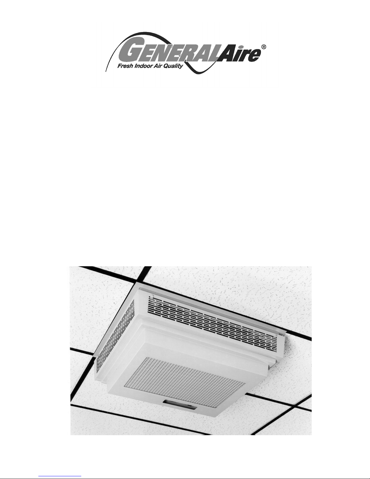
SSCB-7 SERIES
SEMI-FLUSH CEILING MOUNTED
ELECTRONIC AIR CLEANER
IMPORTANT: PLEASE READ MANUAL BEFORE INSTALLING,
OPERATING, CLEANING OR SERVICING UNIT
Page 2
IMPORTANT: Please read entire instructions before
installing the Electronic Air Cleaner.
CONTENTS
SAFETY CONSIDERATIONS 2
WHAT THE ELECTRONIC AIR CLEANER DOES 2
BENEFITS 2
HOW IT WORKS 2
MAJOR COMPONENTS 3
INSTALLATION 3-4
Mounting 3
Wiring 4
OPERATION & MAINTENANCE 4
Operation Check 4
Maintenance Schedule 4
Cleaning 4
SERVICE 5-7
Testing For High Voltage At Power Board 5
Measuring High Voltage At Power Board 5
Replacing A Performance Light 5
Replacing A Power Board 5
Testing The 24 V Transformer 6
Replacing The 24 V Transformer 6
Setting Voltage Of Power Board 6
Setting Approximate Voltage Without High Voltage Meter 6
Testing For Voltage at The Cell 6
Testing Cell For Bad Contacts 7
Testing Cell With An Ohmmeter 7
Replacing A Tungsten Wire 7
Replacing A Fan Motor 7
REMOTE SWITCH CONTROL 7
Electrical Schematic 8
TROUBLESHOOTING GUIDE 9
Exploded View 10
Parts List 10
Technical Data and Dimensions 11
WARRANTY 12
Certified for shock and electrical fire hazard only.
SAFETY CONSIDERATIONS
Read and follow instructions carefully. Follow all local
electrical codes during installation. All wiring must
conform to local and national electrical codes. Improper
wiring or installation may damage the Air Cleaner.
Understand the signal words WARNING and
CAUTION which are present in the Installation, Operation
& Service Instructions.
WARNING and CAUTION signifies a hazard which
could result in property damage, personal injury or death.
Installation and servicing of Electronic Air Cleaners
can be hazardous. Only trained and qualified service
personnel should install, repair, or service Electronic
Air Cleaners.
Untrained personnel can perform the basic
maintenance functions of cleaning and replacing
filters.
When working on air cleaning equipment, observe
precautions in the manual, labels attached to the unit,
and other safety precautions that may apply. Follow
all safety codes. Wear safety glasses and work
gloves.
WHAT THE ELECTRONIC AIR CLEANER DOES
Your High Efficiency Electronic Air Cleaner has been
designed to remove tobacco smoke particles, cooking
smoke and grease, atmospheric dust, coal dust,
insecticide dust, mites, pollen, mold spores, fungi,
bacteria, viruses and more down to 0.01 micron (0.01
micron = 1/2,540,000 of an inch).
BENEFITS
Helps clear up a smokey environment quickly, so
customers can dine more comfortably.
Helps employees reduce suffering from irritated eyes,
nasal congestion and respiratory problems that lead
to absenteeism.
Helps prevent damaging black and greasy particles
from staining ceilings, walls and furnishings, reducing
the amount of housekeeping and redecorating costs.
Helps to lower energy bills by recycling air rather than
exhausting expensive heated or cooled air.
HOW IT WORKS
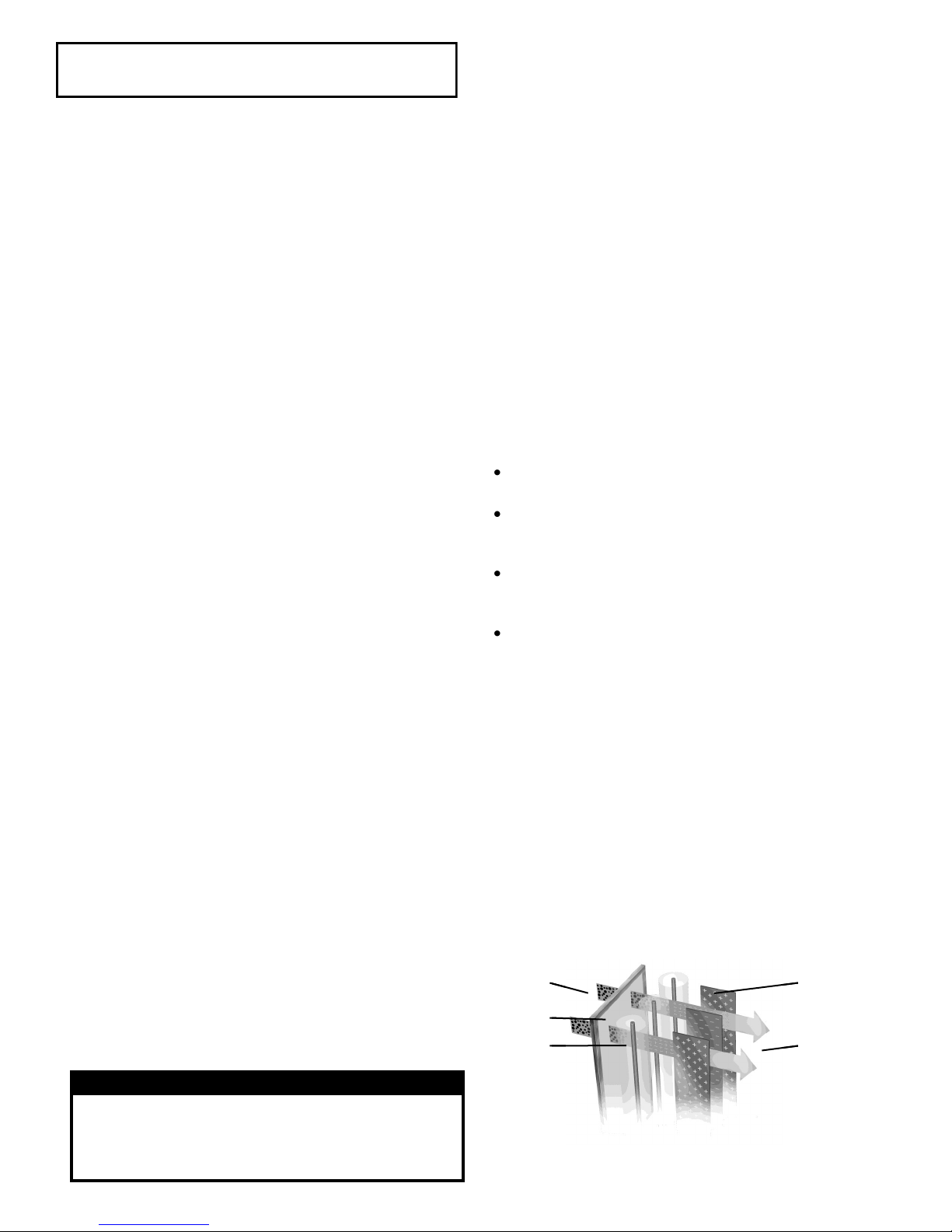
This Air Cleaner works on the principle of
"Electrostatic Precipitation". Millions of airborne pollutants
are drawn through the intake grill on the bottom of the Air
Cleaner and first pass through a Prefilter which removes
all large visible particles such as lint. Next, smaller
particles move to a two-stage electrostatic Collecting Cell
where they are given a powerful positive charge by the
ionizing wires. Charged particles then move into the
collecting area where they are attracted to a series of
grounded plates. Pollutants are held in this section like a
magnet until washed away during cleaning. Clean air is
then dispersed from the side grills in four directions
allowing superior air flow circulation.
1 Dirty Air
1 Dirty Air
2 Prefilter
2 Prefilter
3 Charging
3 Charging
Section
Section
4 Collecting Cell
4 Collecting Cell
Plates
Plates
5 Clean Air
5 Clean Air
WARNING
Before beginning any installation or modification, be
certain that the main line electrical disconnect switch is
in OFF position. Electric shock could result. Tag
disconnect switch with suitable warning labels.
2
2
Fig. 1 — Electrostatic Precipitation
Fig. 1 — Electrostatic Precipitation
Page 3
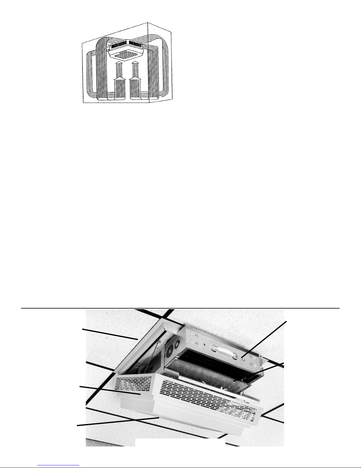
The Air Cleaner
creates a circular air
flow pattern which
never allows air to
rest at the ceiling.
Fig. 2 — Coanda Air Flow
MAJOR COMPONENTS
Description
The Electronic Air Cleaner is approximately 24 x 28 x
15 in (61 x 71 x 38 cm) with 6 in (15.2 cm) of the unit
above the ceiling. The cover and exhaust grill which
remain below the ceiling are hinged to allow access to the
cell and power board. The unit is rated at 700 CFM (1190
m3/hr) on the highest speed setting.
Cabinet
The cabinet is constructed of 20 gauge steel. The
external parts have a tough powder-coated, scratchresistant finish. Access to the collecting cell, power box
and prefilter is made by releasing the latches of the cover
and allowing it to swing down.
The cover is interlocked to cut power to the unit when
opened.
Prefilter
The washable prefilter measuring 12.5 x 20 in (31.75
x 50.8 cm) is constructed of multi-layers of aluminum
mesh for maximum filtration of large particles.
Collecting Cell
The dual voltage collecting cell is constructed of
heavy gauge aluminum to resist rust and damage. The
first stage, the ionizing section, is charged at
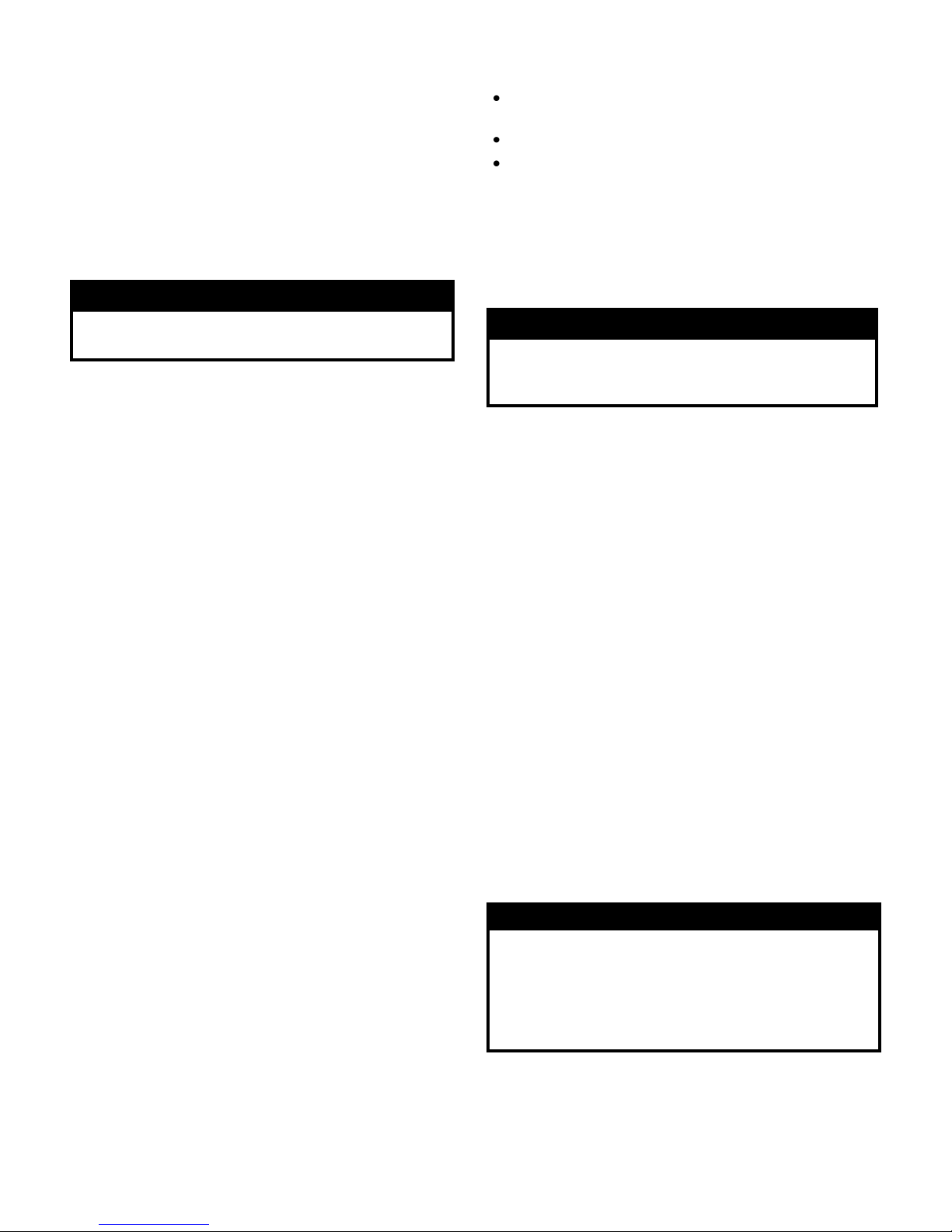
Blower and motor are
hidden above ceiling tiles
for space conservation.
Advantageous for low
ceiling applications where
a larger unit would be
obstructive.
Hinged cover provides
convenient access to grill,
prefilter, collecting cell and
electrical compartment.
Safety interlock cuts power
when cover is opened.
Rear hinges permit smooth
release of cover for easy
installation.
Removable intake grill for
easy cleaning.
approximately 7500 VDC. The collecting plates are
alternately grounded and charged at 5000 VDC. The
arrow on the cells indicates the direction of air flow which
must point up towards the fan motor.
Motor and Fan Blade
The motor is 1/33 HP, 1050 RPM, 3-speed, controlled
by a 3-position slide switch. The motor is thermally
protected. The fan blade is 14 in (35.5 cm) with a 20o
pitch.
Electrical Compartment
The removable power box contains the speed control,
system switch, high voltage power board, and
performance indicator light.
The interlock switch is located in the cabinet
body near the wiring compartment.
INSTALLATION
1. Read instructions carefully. Failure to do so may
result in product damage or injury.
2. Make sure the sizing is correct for your application.
3. Installation should be done by a knowledgeable
technician.
4. After installation, check out operation as provided in
these instructions.
Mounting
1. Remove the unit from the box and lay the unit on its
back, grill side up.
2. Release the grill by pushing the levers, located in the
exhaust grill, toward each other and lift up.
4. Remove the ‘S’ hook from each chain, tilt cover up
until the cover releases from the back hinges.
5. Remove the cell and prefilter from the unit.
6. Holes are provided in the cabinet to accommodate
5/16 in (8 mm) threaded rod. Threaded rod can be
attached to the angle iron which is laid across the
joists, by drilling holes through these supports. Pass
threaded rod up through the supports and secure with
two nuts and washers. This will allow adjustment of
Heavy duty collecting
cell captures airborne
pollutants and simply
washes clean.
Washable, aluminum
mesh prefilter catches
lint and large particles
before they enter
collecting cell.
3-speed fan control
(not shown) allows
adjustment of air flow
to activity level in room.
Fig. 3— Components
3
Page 4
the unit so that the flange is flush with the underside
of the ceiling.
Leave enough room around the Air Cleaner for
removal of collecting cell and prefilter.
7. Replace the cell, prefilter and cover. Hook up the
safety chain to the cover.
Do not hang the unit with chain only. This will not
give the unit the necessary stability when removing
the cells or servicing the unit.
Wiring
WARNING
The frequency of cleaning will vary from one environment
to another. The following is an average wash cycle:
Stores, Offices, Computer & Conference Rooms = 4
Weeks
Cafeterias, Restaurants, Lounges = 3-4 Weeks
Bars, Bingo halls = 1-3 Weeks
The unit should be checked on a regular basis to
determine the frequency of cleaning required in each
location and a cleaning schedule established.
Cleaning
Electrical shock can cause injury or death. Be certain
main line disconnect switch is off before wiring.
All wiring must comply with applicable codes and
standards. See unit rating label for correct voltage and
amperage.
1. Two knockouts are provided, one on top and one on
the side of the unit, adjacent to the wiring
compartment. For convenience, a wall switch may be
installed near the Air Cleaner, in series with the
power source, to turn the unit on and off.
2. Remove the cover of the wiring compartment to
locate the input leads and ground stud. The Air
Cleaner must be grounded for proper operation and
safety.
3. Once the unit is mounted and wired, the cover can be
replaced on the hinge and the chain replaced on the
"S" hooks. Close the cover by sliding the levers
toward the center and pushing the cover up into
place. Release levers to lock the cover into place.
For information on wiring the remote switch
control see page 7.
OPERATION & MAINTENANCE
Operation Check
1. With the cell and prefilter in place and the cover
closed, turn the system switch ON.
2. Adjust the fan speed with the slide switch. Insure the
unit functions on all speeds.
3. The performance light should be ON, which indicates
the power board is functioning properly.
4. If the unit is not functioning properly see the
"Troubleshooting Guide"
When the Air Cleaner is new it may arc or periodically
make "snapping sounds". A slight odor of ozone may be
noticeable. The arcing and odor are due to rough edges
and burrs on the cell. These symptoms will disappear
during the first few weeks of normal operation. The ozone
levels are well below government standards for indoor air
concentration.
Maintenance Schedule
The collecting cell and prefilter must be cleaned on a
regular basis for the unit to function at its peak efficiency.
CAUTION
Make sure Air Cleaner switch is OFF before
performing any maintenance or removing any
components.
1. Turn off the system switch and wait 15 seconds for
high voltage to dissipate.
2. Open the cover and cell access door and remove
collecting cell and prefilter. Cell plates are sharp.
Handle with care.
3. Place cell in tub and spray completely with DAX
Detergent, allowing detergent to run down both sides
of plates and ionizing wires. Let sit for 5 minutes.
Rinse cell well with hot water (140ºF / 60ºC
maximum). Repeat washing process if necessary.
4. If dirt or nicotine remains on plates, let cell soak in hot
soapy water for 30 minutes. Never use any
instrument to clean the cell, as this may damage
the ionizing wires or bend cell plates.
5. Spray prefilter with DAX Detergent and rinse well.
6. To dry cell, tilt on 45º angle against wall with the
arrow pointing sideways. Allow to dry completely for
10-24 hours. Place in sunlight for faster drying time.
7. When the cell and prefilter are dry, place them back
into the unit. The arrow on the cell points up. The red
fiberboard on the cell should line up with the contacts
in the cabinet. Close door and cover. If the cell arcs
when the switch is turned on or if the performance
light does not come on, then the cell may be still wet.
Allow more time for drying.
CAUTION
Damage to cell may occur if improperly handled or
washed. Do not wash cell in a dishwasher. Never
use any object to clean between the cell plates, as this
may cause damage to plates or ionizing wires. Never
place cell in oven to dry. The edges of the cell may be
sharp - handle with care.
The use of DAX Detergent is strongly recommended
for cleaning as it is a heavy-duty solution used expressly
for removal of accumulated pollutants on cell plates. If
used as directed, DAX will not harm aluminum or steel.
Any problem arising out of the use of another cleaning
agent will void the warranty. Do not use detergents that
4
Page 5

are corrosive or abrasive or detergents containing
chlorine or ammonia.
Fig. 4 — DAX Detergent is
available in 35 ounce (1 litre)
spray bottles or 1 gallon (4.54 L)
and 4.8 gallons (22 L) containers
from your installer or dealer.
SERVICE
WARNING
Electronic Air Cleaners use high voltage (low
amperage). Only trained personnel should perform
service. USE CAUTION! Electric shock can cause
injury or death.
CAUTION
For most troubleshooting the cell should be
removed from the Air Cleaner. A short in the cell will
cause the power board to shutdown and the
performance light will stay off. Unless otherwise
directed remove the cell from the unit when testing.
The Air Cleaner when operating normally will have
the fan running and the performance indicator light ON. If
this is not the case the see the Troubleshooting Guide for
probable causes and remedies.
WARNING
When performing LIVE tests in the power box NEVER
touch any parts other then what are mentioned in the
tests. Components carry dangerous voltages and
extreme care must be taken.
Testing For High Voltage At Power Board
For the following test you will need to have the hinged
cover open with the collecting cell out of the unit.
1. Remove the hinged cover and the cover panel to the
power box. Push a screwdriver into the slot to defeat
the interlock switch and turn the Air Cleaner ON.
2. With a long shafted screwdriver, with a plastic handle,
short between the grounded side of the power box
and the HV1 terminal of the power board.
3. If you draw a good spark, there is high voltage from
the power board.
Measuring High Voltage At Power Board
A high voltage meter capable of measuring up to
10,000 VDC is required to test the voltage.
1. The Air Cleaner should be ON with the cell installed
and the cell access door closed. The Air Cleaner
should be on at least 5 minutes to allow voltage to
stabilize.
2. Remove the hinged cover and the cover panel from
power box.
3. Connect the ground of the high voltage meter to
ground stud in the power box.
4. Turn the Air Cleaner ON, and defeat the interlock
switch.
5. Check terminals HV1 and HV2 on the power board to
determine if voltage is present. See Fig. 5 for values..
5. If no voltage is present, remove the cell from the Air
Cleaner.
a. Check the voltage at HV1 and HV2 again.
b. If voltage is present, the problem is with the cell
or the wiring to the copper contacts.
c. Check the condition of the copper contacts and
wiring.
d. If the contacts are not bent and the wiring is OK,
the problem is with the cell. See the
Troubleshooting Guide for more information.
e. If there is no voltage with the cell removed, check
the power board, system switch and transformer
to make sure that they are functioning correctly.
6. If there is voltage present, but the performance light
does not come on, replace the light.
7. The high voltage can be adjusted with the
potentiometer on the power board if required.
Replacing A Performance Light
Before replacing the performance light, turn OFF
power to the Air Cleaner at the source.
1. Remove the cover and the power box cover panel.
2. Disconnect the performance light wiring connected to
the neon lamp terminals (P5 and P6) on the power
board. Carefully cut the wire ties from the wire
bundle.
3. Push the light out through front of power box.
4. Push the new light into the power box.
5. Connect the wiring to the neon lamp terminals on the
power board, P5 and P6. Route the wires away from
the high voltage section of the power board.
6. Replace cover panel and close the cover.
7. Return power to Air Cleaner. Test light.
Replacing A Power Board
Before replacing the power board, turn OFF power to
the Air Cleaner at the source.
1. Remove the cover and the power box cover panel.
2. Disconnect the wiring from the neon lamp, HV1, HV2
and 24 V terminals. Make note of position of wires.
3. Remove the hex nuts from the power board.
4. Remove the power board from the studs.
5. Place the new board onto studs with the 24 volt input
close to the transformer.
5
Page 6

6. Replace the hex nuts removed in Step 3. Ensure the
star washer is in place over the nut at the ground
location under the power board. For proper grounding
the washer must be located under the power board.
7. Reconnect wiring to neon lamp, HV1, HV2, and 24 V
terminals on the new power board. See Fig. 5.
8. Return power to Air Cleaner. Test power board.
9. Replace power box cover panel and close cover.
Note: The power board has been set before shipping. It
is not usually necessary to reset the voltage to the new
load. If you do need to adjust the voltage refer to Setting
Voltage of Power Board section for more information.
Testing The 24 V Transformer
1. Remove the cover and cover panel to the power box.
2. Disconnect the leads of the 24 V transformer from the
power board. See Fig. 5. Do not short the leads.
3. Push a screwdriver into the slot to defeat the interlock
switch and turn the Air Cleaner ON.
4. Measure the voltage across the leads with a
voltmeter. Voltage should read 25 - 28 VAC.
5. If no voltage is present, check the voltage from the
system switch.
6. If there is voltage to the transformer but no output,
replace the transformer.
Replacing The 24 V Transformer
Before replacing the transformer, check the
resistance across the power board 24 V input terminals,
without the transformer connected. Resistance should
read above 20K ohms with an analog meter and above
4M ohms with a digital meter. If the resistance readings
are below these values, the power board may be the
cause of the transformer failure.
Before replacing the 24 V transformer, turn OFF the
power to the Air Cleaner at the source.
1. Remove the cover and power box cover panel.
2. Disconnect the secondary leads from the transformer
to the 24 V terminals on the power board. See Fig. 5.
3. Remove the black primary lead from the system
switch. Remove the wire nut from the other primary
lead.
4. Remove the 2 hex head nuts and washers from the
transformer studs.
5. Remove the transformer.
6. Place new transformer over studs and re-install the
hex head nuts and washers to secure into place.
7. Connect the secondary leads (white) to the 24 V
terminals on the power board (P1 & P2).
8. Place one black lead on the system switch terminal.
9. Place the other black lead with the two white leads
from the terminal block and connect with the wire nut
you removed earlier.
10. Replace power box cover panel and close cover.
11. Turn ON the power to the Air Cleaner and test.
Setting Voltage Of Power Board
Voltage on the power board may drop below required
level when the installation area is too damp, too cold or
the input power to the unit is low. Voltage on power board
may be too high when the installation area is too dry or
too hot or the input power to the unit is high. By adjusting
the HV Adj. potentiometer, the voltage can be set to
optimum level. A high voltage meter capable of
measuring 10,000 VDC is required. To test and adjust
voltage level, perform the following procedure:
1. Turn the Air Cleaner ON and wait 5 minutes before
checking voltage to allow voltage on cell to stabilize.
2. Turn the Air Cleaner OFF, with the cell in the unit.
3. Remove cover and the power box cover panel.
4. Connect the ground of the high voltage meter to the
ground stud in the power box.
5. Turn the Air Cleaner ON and defeat interlock switch.
6. Measure the voltage at HV1 and HV2 on the power
board.
7. Adjust the HV Adj. potentiometer until the voltage
reading matches the voltage in Fig. 5. Adjusting the
potentiometer clockwise decreases the voltage and
turning counter-clockwise increases the voltage.
8. Turn OFF the Air Cleaner.
9. Remove the high voltage meter.
10. Replace the power box cover panel and close cover.
11. Turn ON the Air Cleaner.
Setting Approximate Voltage Without High Voltage
Meter
A high voltage meter should be used to set the high
voltage. If one is not available, this method can be used.
This will only set an approximate voltage. After using this
method, the voltage should be reset with a high voltage
meter as soon as possible.
1. Remove power box cover panel, with the cell in the
unit.
2. Turn the HV Adj. potentiometer fully counter-
clockwise. The Air Cleaner may arc or snap at this
point.
3. Turn the HV Adj. potentiometer clockwise
approximately a quarter turn.
4. Replace power box cover panel and close cover.
Testing For Voltage At The Cell
1. Remove the cover and power box cover panel.
2. The cell must be in the Air Cleaner for this test.
3. Turn the Air Cleaner ON and defeat the safety
interlock switch.
4. Place a plastic handled screwdriver into the direction
arrow slot. Do not apply excessive force.
5. If there is a good snap then there is high voltage at
the cell.
6
Page 7

Testing Cell For Bad Contacts
1. Remove the cover and power box cover panel.
2. The cell must be in the Air Cleaner for this test.
3. Turn the Air Cleaner ON and defeat the safety
interlock switch.
4. Place a plastic handled screwdriver into the direction
arrow slot. Do not apply excessive force.
5. There should be an initial snap when the plates are
shorted, then no sound. If a hissing occurs, then
there is a bad contact. Look along the top of the cell,
with the short still in place. If there is a small arc
between the cell top and copper contact, then that is
the bad contact. Pull the cell out and gently pull the
copper contact down.
6. If an arc is not seen and there is a bad contact, then
the problem may be an internal contact in the cell.
See below for additional testing.
Testing Cell With An Ohmmeter
To test the cell for a dead short or a bad contact an
ohmmeter can be used. Always discharge the cell with
a screw driver before testing with an ohmmeter.
1. With the ohmmeter set on its lowest scale take a
reading between the top center contact of the cell and
the ionizing fingers on the bottom of the cell. You
should have continuity. If you do not then there is a
bad contact between the center contact and the top
set of ionizing fingers.
2. Test the resistance between the top center contact
and the cell frame. You should read infinite
resistance. If not you have a short in the ionizing
section.
3. Take a reading between the two outside contacts on
the top of the cell. You should have continuity. If you
do not then there is a bad contact between one of the
contacts to the live cell plate. Test each top outside
contact to the last plate in the cell to determine which
contact is not mating properly.
4. Test the resistance between the outside contacts and
the cell frame. You should read infinite resistance. If
not you have a short in the collecting section.
Replacing A Tungsten Ionizing Wire
Replacement wires are cut to the correct length and
have eyelets at each end for easy replacement.
1. Turn OFF power to Air Cleaner.
2. Remove cell from Air Cleaner.
3. Remove all parts of broken wire from the cell. If
necessary, the cell may be used temporarily with one
wire missing until a replacement is received.
4. Place one end of the loop over the finger at the
bottom of the cell.
5. Using needle-nose pliers, grip the other end of wire,
near the bottom of the top loop. Pull the wire up
toward the top finger. As you apply tension, the
bottom finger will give, allowing the placement of the
loop around the top finger.
6. Install cell in Air Cleaner.
7. Return power to Air Cleaner.
8. Test cell for proper operation.
Replacing A Fan Motor
1. Turn OFF power to Air Cleaner at the source.
2. Open the cover and remove cells and prefilters from
Air Cleaner.
3. Remove the fan blade from the motor shaft.
4. Remove the cover and power box cover panel.
Disconnect the four motor wires from the terminal
block. Gently pull the wires up into the motor
compartment.
5. Remove the four hex nuts holding the motor plate to
the cabinet. Remove the motor and plate.
6. Remove the four hex nuts from the back of the motor
plate to release the motor.
7. Replace the isolator rubbers on the motor plate.
8. Attach the new motor to the motor plate with a flat
washer on both sides of the rubber isolator. Place the
motor plate into the cabinet with the wires toward the
plastic bushing to allow the wires to be feed to the
power box.
9. Secure the motor plate to the cabinet.
10. Feed the motor wires down through the plastic
bushing and secure to the terminal block.
#3 - White
#4 - Red
#5 - Yellow
#6 - Black
The white wire on units with a remote switch control
use a wire nut instead of terminal #3.
11. Reinstall the fan blade, cell and prefilter.
12. Replace the power box cover panel and close the
cover.
13. Turn ON the Air Cleaner and test the motor on all
speeds.
REMOTE SWITCH CONTROL
The remote switch control, if ordered with the unit,
has two switches which control power to the unit and
control the speed of the motor. The remote switch control
cannot be added to a non-remote unit.
The switch control can be mounted in a convenient
location and wired back to the unit to control the
functions. The control box has holes on the back for
mounting and knockouts on five sides for the electrical
wires to be attached. A terminal block is mounted inside
the box to facilitate wiring.
Run an approved seven wire cable between the
control box and the unit. Refer to Fig. 6 for wiring
connections between the control and the unit. Both the
remote box and the unit must be grounded for proper and
safe operation.
7
Page 8

Fig. 5 — Electrical Schematic - 120 Volt
Fig. 6 — Electrical Schematic - With Wired Remote - 120 Volt
8
Page 9

Table 1 — TROUBLESHOOTING GUIDE
PROBLEM PROBABLE CAUSE REMEDY
Unit does not function
correctly. Power switch
ON and performance
indicator light and
motor are OFF.
Unit does not function
correctly. Power switch
is ON, motor is
operating and
performance indicator
light is OFF.
Unit does not function
correctly. Power switch
is ON, motor is not
operating and
performance indicator
light is ON.
Cell makes loud hissing
noise or causes radio
interference.
Cell arcing excessively
(performance indicator
light ON or flashing).
Main breaker or fuse. Check breaker or fuse and reset or replace if necessary.
Remote switch off. If equipped with a remote switch ensure it is turned on.
Wiring or plug improperly connected. Check wiring or if plug is inserted and receptacle is powered.
Cover not closed. Close cover and latches locked in place.
Defective power switch. Check power switch for continuity with ohmmeter. Replace if defective.
Defective safety interlock. Open cover and press safety interlock with a screwdriver. If lights come
Short in cell due to:
1. Broken ionizing wire.
2. Large particles wedged between cell plates.
3. Cell washed recently and are still wet.
4. Cell end plate insulator is dirty or damaged.
5. Cell plates are bent.
Defective performance indicator light. Determine whether high voltage is present by testing power board. If
Defective power board.
(Check power board with cells removed)
Off board 24 V transformer is not working. Verify output of transformer. Replace if necessary.
Defective power switch. Verify output of switch. Replace if necessary.
Defective power switch. Check power switch for continuity with ohmmeter. Replace if defective.
Defective speed selector switch. Check switch for continuity with ohmmeter. Replace if defective.
Defective fan motor. Test motor and replace if defective.
Internal cell contacts are not touching plates. Test contacts and repair.
High voltage copper contacts not making good
connection on cell.
Cell wet from washing. Allow cell to dry completely.
Particles lodged in cell or broken ionizing wire. Wash cell. Shake particle out of cell. Replace wire, if necessary.
Cell plates are bent. Remove cell and adjust to original spacing using needle-nose pliers.
on, check if interlock bracket is bent.
1. Remove wire or wire fragments. Replace.
2. Shake large particles out or wash cell.
3. Allow cell to dry completely.
4. Clean or replace end plate insulator.
5. Straighten plates with pliers.
voltage is present, replace indicator light.
Adjust high voltage potentiometer on power board counter-clockwise. If
high voltage is not present check transformer and switches. Replace
power board if 24 V is present to power board.
With needle-nose pliers, gently pull contacts down or replace contacts.
Voltage is too high. Adjust high voltage potentiometer on power board clockwise.
High voltage wires are on wrong copper contact. Reposition high voltage wires on proper contact (see Fig. 5).
Internal contact on cell out of alignment. Realign cell contact.
Cell arcing excessively
at top of cell near
copper contacts (power
light and performance
indicator light ON).
Cell not collecting dirt
(performance indicator
light ON).
Ozone odor
Copper contact on high voltage contact board is
broken or bent upward.
Arrow on cell not pointing towards fan motor. Reposition cell handle and place cell in properly.
Not enough voltage on collecting cell. Adjust high voltage potentiometer counter-clockwise on power board.
Cell plates are bent. Straighten with needle-nose pliers.
Loose or broken ionizing wire. Replace wire.
Dirty cell. Wash cell.
Incoming voltage is higher than 120 V. Adjust high voltage potentiometer clockwise on power board.
Air Cleaner is oversized for room. Use correct size of Air Cleaner.
Room is extremely dry. Repair or install central humidifier.
If possible, pull down contact with needle-nose pliers or replace
contact.
9
Page 10

Fig. 7 — Exploded View and Parts List
# Description Part Number
1 Fan Motor EACCM7-01
2 Fan Blade EACCM7-02
3 Copper Contact EAC14-08
4 Fibreboard (with 2 Copper Contacts) EACCM7-04
5 Intake Grill EACCM7-05
6 Cover Assembly (incl. Grill) (White) EACCM7-06W
6a Cover Assembly (incl. Grill) (Gray) EACCM7-06G
7 Collecting Cell EACCM7-07
8 Cell Handle EAC14-16
9 Ionizing Wire EAC20-19
10 Safety Interlock Switch EACCM13-10
11 Red Indicator Light EACCM13-11
# Description Part Number
12 Power Switch (Gray) EACCM13-12W
12a Power Switch (Black) EACCM13-12G
13 3-Position Slide Switch (Gray) EACCM13-13W
13a 3-Position Slide Switch (Black) EACCM13-13G
14 Power Board Fibreboard EACCM13-14
15 Power Board EACCM13-15
16 24 Volt Transformer EACCM13-16
17 Cell Guide EAC14-14
18 Prefilter EACCM13-18
19 Remote Switch Box EACCM13-19
20 Door Label (Close Door Latch...) EACCM13-20
21 Dax Detergent 9900
Use the diagram above to identify the part which is required. To order parts call the number
listed below or call your local contractor.
10
Page 11

Dimensions Length 24 in 61.0 cm
Width 28 in 71.0 cm
Height 15 in 38.1 cm
Weight 70.0 lbs 32.0 kg
Input Voltage 120 V 60 Hz
Power
Consumption
(maximum)
Air Flow Hi 712 CFM 1210 m3/hr
Medium 575 CFM 977 m3/hr
Low 440 CFM 748 m3/hr
Motor 1/33 HP
150 Watts
Table 2 — Technical Data Fig. 8 — Dimensions
Notes
11
Page 12

ELECTRONIC AIR CLEANER
LIMITED ONE YEAR WARRANTY
Electronic Air Cleaners, if properly registered by the return of the attached warranty registration to
General Filters, Inc., are warranted to the consumer against defects in materials and workmanship
for a period of one year from the date of installation, so long as the product has been installed and
operated in accordance with all appropriate manuals and wiring diagrams. Replacement or
routinely replaceable parts such as prefilters, are not covered by this limited warranty or any other
warranties. Any other defective parts will be repaired without charge except for removal,
reinstallation and transportation costs. To obtain repair service under this limited warranty, the
consumer must send the defective part to General Filters, Inc.
THERE ARE NOT EXPRESS WARRANTIES COVERING THIS ELECTRONIC AIR CLEANER
OTHER THAN AS SET FORTH ABOVE. THE IMPLIED WARRANTIES OF MERCHANTABILITY
AND FITNESS FOR A PARTICULAR PURPOSE ARE EXPRESSLY EXCLUDED. THE
MANUFACTURER ASSUMES NO LIABILITY IN CONNECTION WITH THE INSTALLATION OR
USE OF THIS PRODUCT, EXCEPT AS STATED IN THE LIMITED WARRANTY. THE
MANUFACTURER WILL IN NO EVENT BE LIABLE FOR INCIDENTAL OR CONSEQUENTIAL
DAMAGES.
This limited warranty gives you specific legal rights, and you may also have other rights which vary
from state to state. Some states do not allow either limitations on implied warranties, or exclusions
from incidental or consequential damages, so the above exclusion and limitation may not apply to
you.
Any questions pertaining to this limited warranty should be addressed to General Filters, Inc.
General Filters, Inc. has elected not to make available the informal dispute settlement mechanism
which is specified in the Magnuson-Moss Warranty Act.
14463
eaccm7-1.pub
08/10
 Loading...