

Page 1
R
Fresh Indoor Air Quality
READ AND SAVE THESE INSTRUCTIONS
SL-16
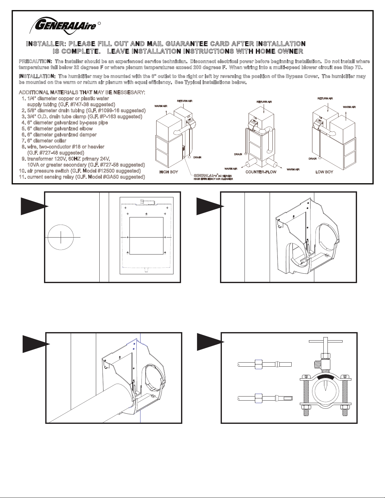
INSTALLER: PLEASE FILL OUT AND MAIL GUARANTEE CARD AFTER INSTALLATION
IS COMPLETE. LEAVE INSTALLATION INSTRUCTIONS WITH HOME OWNER
PRECAUTION: The installer should be an experienced service technician. Disconnect electrical power before beginning installation. Do not install where
temperatures fall below 32 degrees F or where plenum temperatures exceed 200 degrees F. When wiring into a multi-speed blower circuit see Step 7D.
INSTALLATION: The humidifier may be mounted with the 6" outlet to the right or left by reversing the position of the Bypass Cover. The humidifier may
be mounted on the warm or return air plenum with equal efficiency. See Typical Installations below.
ADDITIONAL MATERIALS THAT MAY BE NESSESARY:
1. 1/4" diameter copper or plastic water
supply tubing (G.F. #747-38 suggested)
2. 5/8" diameter drain tubing (G.F. #1099-16 suggested)
3. 3/4" O.D. drain tube clamp (G.F. #P-163 suggested)
4. 6" diameter galvanized by-pass pipe
5. 6" diameter galvanized elbow
6. 6" diameter galvanized damper
7. 6" diameter collar
8. wire, two-conductor #18 or heavier
(G.F. #727-48 suggested)
9. transformer 120V, 60HZ primary 24V,
10VA or greater secondary (G.F. #727-58 suggested)
10. air pressure switch (G.F. Model #12500 suggested)
11. current sensing relay (G.F. Model #GA50 suggested)
WARM AIR
RETURN AIR
R
DRAIN
WARM AIR
DRAIN
HIGH BOY COUNTER-FLOW LOW BOY
GENERALAire AC SERIES
HIGH EFFICIENCY AIR CLEANER
RETURN AIR
WARM AIR
RETURN AIR
WARM AIR
DRAIN
1
1
OPENING CLEARANCE ABOVE THIS LINE
PREFERRED: 2 1/2 INCH.
MINIMUM: 1 1/2 INCH.
INITIAL
MOUNTING
HOLE
CUT SHEETMETAL ALONG THIS LINE
INITIAL
MOUNTING
HOLE
CENTERLINE
Select location on vertical surface of warm or return air plenum for
mounting humidifier and tape mounting template. Make sure the
template is level. Do not install humidifier or 6" bypass pipe where the
blanked off ends of a cooling coil will restrict air flow to the humidifier.
Extend horizontal centerline from template to the adjacent plenum.
Scribe 6” circle 10” to 15” from side of humidifier, on cabinet centerline.
3
2
CUT TEMPLATE ALONG THIS LINE CUT TEMPLATE ALONG THIS LINE
INITIAL
MOUNTING
HOLE
2
Start the three initial mounting screws. Mount humidifier cabinet in
level position and tighten screws. Install six additional screws at top
and sides of cabinet.
4
4
COPPER
TUBING
PLASTIC
TUBING
Cut 6” hole and install connecting collar, 6” elbow and by-pass pipe
(not supplied). USE UNCRIMPED END IN HUMIDIFIER CABINET.
Connect by-pass pipe to collar and humidifier cabinet. Using holes
at top and bottom of humidifier bypass opening, screw by-pass pipe
to humidifier cabinet. Install bypass cover by placing the tab of the
bypass cover marked "TOP" behind the top flange of the humidifier
cabinet, push up on the bottom clip until it clears the opening of the
humidifier cabinet then push in on the bottom of the bypass cover.
NOTE: If furnace is used for summer cooling, install inline
damper in by-pass pipe.
Mount the self tapping saddle valve on either a cold or a hot water pipe. A
side or top mount is best to avoid clogging from pipe sediment. Connect 1/4”
O.D. tubing to the saddle valve. Copper tubing requires a brass compression
nut and brass sleeve. Plastic tubing requires a brass insert inside the tubing,
a plastic sleeve on the outside with a brass compression nut.
NOTE: DO NOT USE PLASTIC TUBING ON HOT WATER OR IN
CONTACT WITH ANY HOT PLENUM SURFACE OR DUCT.
INSTALLATION OF THIS SADDLE VALVE MUST MEET OR
EXCEED LOCAL CODES AND ORDINANCES.
Page 2
SADDLE VALVE INSTALLATION INSTRUCTIONS
Copper Pipe
1. Retract piercing pin into valve body by turning handle counterclockwise.
2. Screw valve body into upper bracket and tighten.
3. Place rubber gasket over piercing pin.
4. Assemble saddle valve over copper pipe using enclosed screws, nuts
and lower bracket.
5. Tighten screws evenly and firmly. Brackets should be parallel.
6. Complete compression connection to saddle valve outlet.
7. Turn handle clockwise to pierce tubing and close saddle valve.
8. Turn handle counterclockwise to open saddle valve, leave open for
several seconds to flush dirt from pipe and tubing.
Steel, Brass or Hard Plastic Pipe
1. Shut off water supply and drain pipe.
2. Turn handle clockwise to expose piercing pin and close saddle valve.
3. Place rubber gasket over piercing pin.
4. Drill 1/8" hole in pipe using a hand crank drill to avoid shock hazard.
5. Assemble saddle valve over steel, brass or hard plastic pipe using
enclosed screws, nuts and lower bracket.
6. Tighten screws evenly and firmly. Brackets should be parallel.
7. Complete compression connection to saddle valve outlet.
8. Turn handle counterclockwise to open saddle valve, leave open for
several seconds to flush dirt from pipe and tubing.
Threaded Pipe Fittings
1. Turn handle clockwise to expose piercing pin and close saddle valve.
2. Seal valve body threads using pipe tape or sealant.
3. Install valve into 1/8" NPT fitting.
4. Complete compression connection to saddle valve outlet.
5. Turn handle counterclockwise to open saddle valve, leave open for
several seconds to flush dirt from pipe and tubing.
5
5
COPPER TUBING
PLASTIC TUBING
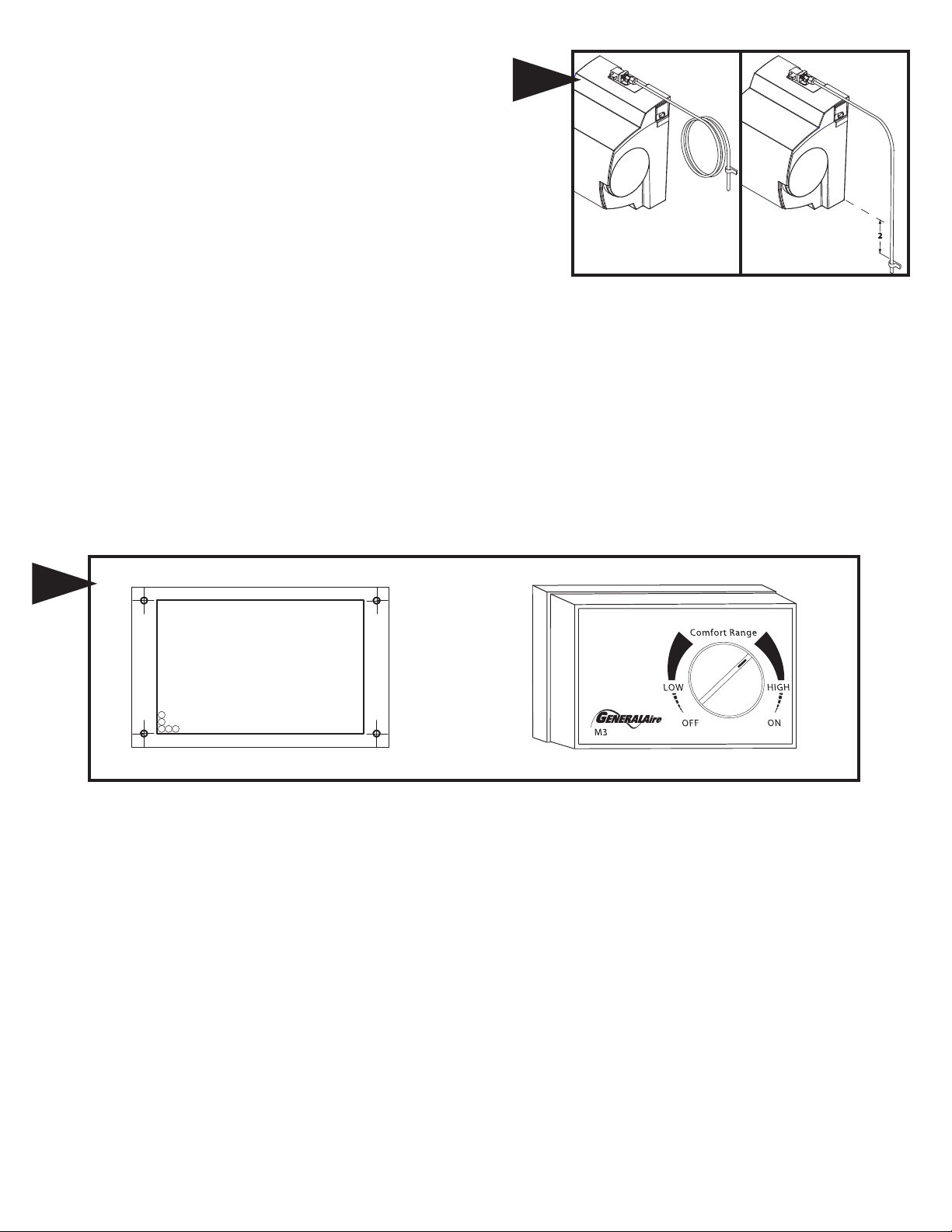
Attach solenoid valve into top of humidifier cover using 1/4 turn rotation.
If using copper tube, leave two coils of tube next to cabinet to allow
cover movement for changing pad. If using plastic tube, anchor tube 2
inches below humidifier and leave some slack. This will allow full cover
6
movement.
Loosen the fitting nut on the solenoid valve 1/2 turn. Push the 1/4" O.D.
tubing straight into fitting until it bottoms on the fitting's shoulder.
TIGHTEN NUT BY HAND. Additional tightening is not required.
DO NOT OVERTIGHTEN NUT AS THE THREADS WILL STRIP
AND THE FITTING WILL NOT FUNCTION PROPERLY.
NOT USE PLASTIC TUBING IN CONTACT WITH ANY HOT
PLENUM SURFACE OR DUCT.
2
DO
6
HAUTTOP
DUCT HUMIDISTAT FLUSH
MOUNTING TEMPLATE
1. REMOVE ADHESIVE BACKING
AND APPLY TO THE DUCT IN THE
SELECTED LOCATION.
2. ACCURATELY CENTER PUNCH
ALL HOLES.
3. DRILL FOUR MOUNTING HOLES
SIZE 3/32", DRILL NO. 42 OR 2 mm.
4. DRILL OTHER HOLES WITH 1/8"
OR 3 mm DRILL.
5. BREAK METAL FROM GROUP OF
HOLES, AND CUT OUT ON SOLID
LINE WITH SHEARS.
TEMPLATE NO. 12807 REV. B MATRICE No 12807
MOUNTING ON THE RETURN AIR DUCT
Do not install the humidistat on the warm air duct.
1. Locate the humidistat at least 24" upstream of the humidifier or bypass
on the return air duct. Avoid areas of direct radiation like secondary
heat exchangers in the fan compartment.
2. Place template using level. Cut sensor hole as shown on template.
Drill four 3/32” holes as shown.
3. Remove the housing from the base by prying with a small screwdriver
at the notch in the side of the housing.
4. Place the outer part of the foam gasket on the humidistat base and
mount the base with four screws. Low voltage wire may enter the
humidistat under the foam seal.
5. Connect wires to screw terminals on the control assembly as shown in
wiring diagram. Replace housing.
GABARIT DE MONTAGE
DE L'HUMIDISTAT ENCASTRÉ
DANS LE CONDUIT
1. ENLEVEZ LE SUPPORT ADHÉSIF ET
POSEZ SUR LE CONDUIT À L'ENDROIT
CHOISI.
2. CENTREZ TOUS LES TROUS AU
POINTEAU AVEC PRÉCISION.
3. PERCEZ QUATRE TROUS DE
MONTAGE DE 3/32 PO (MÈCHE Nº 42 OU
DE 2 mm).
4. PERCEZ LES AUTRES TROUS AVEC
UNE MÈCHE DE 1/8 PO OU DE 3 mm.
5. DÉTACHEZ LE MÉTAL DU GROUPE DE
TROUS ET DÉCOUPEZ SUR LA LIGNE
PLEINE AU MOYEN DE CISAILLES.
COUPER SUR LA LIGNECUT ON LINE
WALL MOUNTING INSTRUCTIONS
1. Chose a location for the humidistat about five feet above the floor on
an inside wall with average room temperature and humidity conditions.
2. Drill a small hole in the wall and run low voltage wiring to the location
chosen. Pull about 6” of wire through the hole. Plug the opening to
prevent drafts from affecting the humidistat operation.
3. Remove the housing from the base by prying with a small screwdriver
at the notch in the side of the housing.
4. Mount the base horizontally over the wires using level. Attach directly
to the wall, using four screws provided.
5. Connect wires to screw terminals on the control assembly as shown
in wiring diagram. Replace housing.
Page 3

7
SNSR
HUM
AC N
AC L
SNSR
HUM
AC N
AC L
OUTDOOR TEMP. SENSOR
WIRE JUMPER
WIRE JUMPER
OUTDOOR TEMP. SENSOR
WIRE
JUMPER
727-58 24 V. TRANSFORMER
ON-OFF SWITCH
FURNACE
CONTROL BOARD
C
24v.
60CY.
R
N
115v.
(HOT)
60CY.
W
W
FURNACE
BOARD
24v.
60CY.
24V. SOLENOID VALVE
7A
24V. SOLENOID VALVE
7C
24V. SOLENOID VALVE
SNSR
HUM
AC N
AC L
SNSR
HUM
AC N
AC L
OUTDOOR TEMP. SENSOR
WIRE
JUMPER
727-58 24 V. TRANSFORMER
24V. SOLENOID VALVE
OUTDOOR TEMP. SENSOR
WIRE
JUMPER
727-58 24 V. TRANSFORMER
C
12500 AIR
PRESSURE SWITCH
ON-OFF SWITCH
NO
ON-OFF SWITCH
CURRENT
SENSING
RELAY
GA50
L2
115v.
60CY.
(HOT)
L1
FURNACE
COMMON LEAD
C
(HOT)
24V. SOLENOID VALVE
7B
C
MULTI
SPEED
HI
BLOWER
LO
MOTOR
115v.
60CY.
7D
24V. SOLENOID VALVE
HUMIDISTAT
HUMIDISTAT
24 V. TRANSFORMER
FURNACE
CONTROL BOARD
C
24v.
60CY.
HUM
ON-OFF SWITCH
FURNACE
BOARD
C
(HOT)
ACC
EAC
24V. SOLENOID VALVE
115v.
60CY.
7A-7D Electronic Humidistat
7A - To furnace control board 24 volts
7B - To constant power using 24V transformer and pressure switch
7C - To furnace control board 115 volts with 24V transformer
7D - To constant power using 24V relay and current sensing relay
8
7E
7G
HUMIDISTAT
C
12500 AIR
PRESSURE SWITCH
24V. SOLENOID VALVE
24 V. TRANSFORMER
NO
24 V. TRANSFORMER
HUMIDISTAT
ON-OFF SWITCH
ON-OFF SWITCH
GA50
CURRENT
SENSING
RELAY
L2
115v.
60CY.
(HOT)
L1
FURNACE
COMMON LEAD
C
(HOT)
115v.
60CY.
7E-7H Manual Humidistat
7E - To furnace control board 24 volts
7F - To constant power using 24V transformer and pressure switch
7G - To furnace control board 115 volts with 24V transformer
7H - To constant power using 24V relay and current sensing relay
9
Remove plastic bag from 990-13 evaporator pad, replace 16-4
distributor trough and close 16-2 cover. Turn on water supply and
check operation of humidifier. Set humidistat to a demand setting.
With the furnace off, the solenoid valve should be closed. Start the
furnace, the solenoid valve should open when the blower or burner
circuit is energized. Check flow of water through distributor trough
and evaporator pad. The solenoid valve will supply approximately 3.5
GPH of water at a line water pressure of 60 psi. Leave humidistat set
at the recommended setting.
7F
C
MULTI
SPEED
HI
BLOWER
LO
MOTOR
7H
Connect drain hose to 5/8" spout on humidifier cabinet using a 3/4" hose
clamp. Run 5/8" I.D. hose to suitable drain such as floor drain, sewer or
laundry sink. Be sure hose has continuous slope and is not kinked at any
point.
Page 4

HOW THE HUMIDIFIER WORKS
The operating principle of the humidifier is based on the most efficient and economical means of evaporating water to
the air. The humidifier uses only five watts of electrical power during operation, less than the smallest household light
bulb. The heat necessary for evaporating water is produced by the furnace.
The water supply to the humidifier is controlled by the electric solenoid valve. The humidistat connected in series
with the solenoid provides low voltage control of the humidifier. The humidistat has a SPST switch and is designed for
wall mounting in the living area or surface mounting on the return air duct. RANGE: 10% to 60% RH ELECTICAL
RATING: 24 VAC / 60 Hz. DO NOT SET RELATIVE HUMIDITY TOO HIGH DURING COLD WEATHER.
EXCESSIVE HUMIDITY MAY CAUSE CONDENSATION ON WINDOWS OR IN WALLS. REFER TO
RECOMMENDED SETTINGS ON HUMIDISTAT.
Water flows through a strainer, is metered through an orifice to provide the proper amount of water, and is supplied to
the evaporator pad by the distributor trough. Approximately 200 CFM of air is by-passed from the warm air plenum
through the humidifier and returned to the cold air plenum. Moisture is evaporated to the air passing through the
evaporator pad.
Minerals are not blown into the air stream as occurs in atomizing humidifiers; they are left on the evaporator pad
where a high percentage is carried off with the waste water.
When the humidifier is installed and operating, no adjustments are necessary other than setting the control knob on
the humidistat to the desired level of humidification.
To turn the humidifier off, close water supply valve, switch electrical power off and turn humidistat off. If furnace is
used for summer cooling or ventilating close inline air damper if installed..
AT
OUTSIDE
TEMPERATURE
-20 F -29 C° 15%
-10 F -23 C° 20%
0 F -18 C° 25%
+10 F -29 C
° 30%
+20 F - 7 C
° 35%
+30 F - 1 C° 40%
RECOMMENDED
°
°
°
°
°
°
SETTING
CARE AND MAINTENANCE
Your Humidifier is engineered to give helpful and trouble-free
humidification. For maximum efficiency the following cleaning
procedures should be carried out at the end of each heating season:
1. Turn off water supply and electrical power to humidifier.
2. Open humidifier cover, remove trough and evaporator
pad. If water line prevents cover opening disconnect water
line from solenoid valve. Clean excessive mineral deposits
from the distributor trough, humidifier cover and humidifier
cabinet. A solution of 1/2 vinegar & 1/2 water will help
loosen mineral deposits.
3. If the evaporator pad has excessive mineral deposits,
replace with a new “990-13” evaporator pad. Install trough
and replace cover.
4. In heavy mineral areas or if the solenoid valve fails to
function disconnect the 1/4” water supply line from the
solenoid valve. Carefully pull the filter from the solenoid
valve. Clean the mineral deposits from all parts. If the
orificebeyond the filter is clogged, it may be opened by
inserting a small needle. Reinsert the filter into the solenoid
valve.
5. Reconnect the 1/4” water line to the solenoid valve if
necessary. Tighten nut by hand, additional tightening is not
required.
DO NOT OVERTIGHTEN NUT AS THE
THREADS WILL STRIP AND THE FITTING WILL
NOT FUNCTION PROPERLY.
supply and check all points for leakage. The operation of
the unit may be checked by starting the furnace. The
humidifier operates only when the furnace blower is running
or the burner circuit is energized. The humidifier is now
ready for operation.
6. During the summer, turn off water supply and electrical
power to humidifier. Close inline air damper if installed.
Turn on the water
PART #990-13
EVAPORATOR
PART #16-1
HUMIDIFIER
PART #16-5
COVERBYPASS
PART #16-4
DISTRIBUTOR
TROUGH
PAD
CABINET
PARTS LIST FOR HUMIDIFIER
PARTS NOT SHOWN:
800UST SADDLE VALVE
HUMIDISTAT ASSY.
Copyright 2012 GENERAL FILTERS, INC.
C
All Rights Reserved
PART #16-2
COVER
PART #16-20
SOLENOID
VALVE ASS'Y
PART #16-12
STRAINER
SCREEN
PART #P-236
SOLENOID
FITTING
HARDWARE
Page 5

PARTS LIST FOR HUMIDIFIER
LIMITED WARRANTY
This humidifier, if properly registered by the return of the warranty registration card to the manufacturer, is warranted to the consumer against defects in
materials and workmanship for a period of ten years from the date of installation. Evaporator pads, water strainers or metering orifices are not covered by this
limited warranty or any other warranties. Any other defective parts will be repaired without charge except for removal, reinstallation and transportation costs.
To obtain repair service under this limited warranty, the consumer must send the defective part or the complete humidifier to the manufacturer.
THERE ARE NO EXPRESS WARRANTIES COVERING THIS HUMIDIFIER OTHER THAN AS SET FORTH ABOVE, THE IMPLIED WARRANTIES OF
MERCHANTABILITY AND FITNESS FOR A PARTICULAR PURPOSE ARE EXPRESSLY EXCLUDED. THE MANUFACTURER ASSUMES NO LIABILITY IN
CONNECTION WITH THE INSTALLATION OR USE OF THIS PRODUCT, EXCEPT AS STATED IN THIS LIMITED WARRANTY. THE MANUFACTURER
WILL IN NO EVENT BE LIABLE FOR INCIDENTAL OR CONSEQUENTIAL DAMAGES.
This limited warranty gives you specific legal rights, and you may also have other rights which vary from state to state. Some states do not allow either
limitations on implied warranties, or exclusions from incidental or consequential damages, so the above exclusion and limitation may not apply to you.
Any questions pertaining to this limited warranty should be addressed to the manufacturer. (U.S.A.: The manufacturer has elected not to make available the
informal dispute settlement mechanism which is specified in the Magnuson-Moss Warranty Act.)
TECHNICAL SUPPORT
USA CUSTOMERS
General Filters, Inc.
43800 Grand River Ave.
Novi, MI 48375
www.GeneralAire.com
Engineering@generalfilters.com
Toll Free (866) 476-5101
Product Information:
Serial Number: _____________________________________________________________
Model: ____________________________________________________________________
Install Date: Month _______________ Day ______________ Year _____________
Owner Information:
Name: _____________________________________________________________________
Address: ___________________________________________________________________
Address 2: __________________________________________________________________
City: _______________________ State: ___________ Zip Code: ____________________
Phone: _____________________________________________________________________
Email: ______________________________________________________________________
Contractor Information:
Contractor Name: _____________________________________________________________
Address: ____________________________________________________________________
Address 2: ___________________________________________________________________
City: _____________________ State: ___________ Zip Code: _______________________
Contractor Phone: ____________________________________________________________
Contractor Email: _____________________________________________________________
CANADIAN CUSTOMERS
Canadian General Filters, Ltd.
400 Midwest Rd.
Toronto, ON M1P3A9 Canada
www.CGFProducts.com
Sales@cgfproducts.com
Tel. (416) 757-3691
WARRANTY REGISTRATION
You may register online at www.GeneralAire.com or mail form below
R
Fresh Indoor Air Quality
Mail Form To:
General Filters, Inc
Attn: Warranty Dept.
43800 Grand River Ave.
Novi, MI 48375
cut along dashed line
cut along dashed line
 Loading...