

Page 1
Page 2
TROUBLESHOOTING
• Under normal operation the LED should light when the unit has been supplied power.
If the LED does not light:
1. Check to be sure there is power to the unit.
2. Be sure lamp connector is fastened securely.
3. If the LED still does not light, replace lamp.
4. If still not operating, replace ballast.
ARRANTY
W
The manufacturer warrants the GUV-161 air purification unit against defects in
materials and workmanship for a period of four (4) years from the date of installation.
Lamps carry a warranty for the useful life of the lamp, two (2) years .
This warranty does not cover broken lamps due to shipping, installation or handling.
This warranty gives you specific legal rights and you may also have other rights which
vary from state to state.
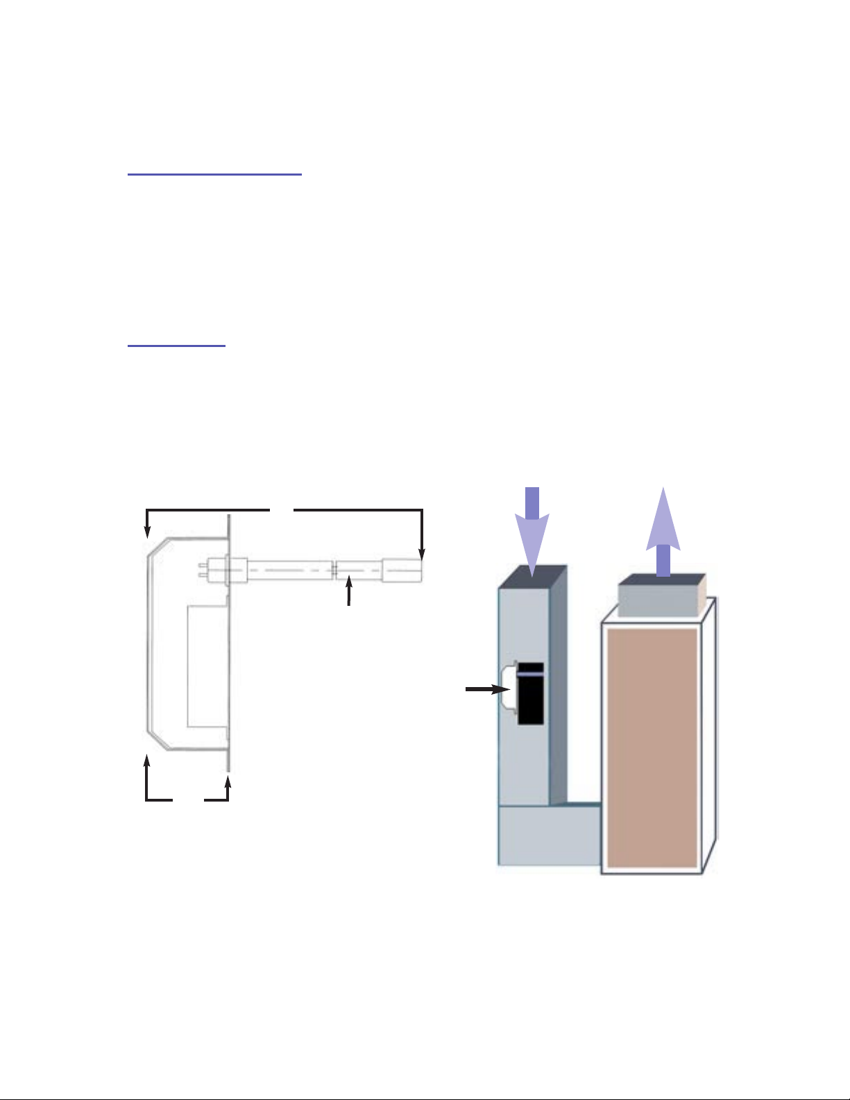
2.75”
18”
16” Germicidal UV-C Lamp
Box size is
8.25 high x
4.25 wide.
Air flow
GUV-161
Furnace
Return
Air Duct
© 2005 For service please call 248-476-5100
Page 3

GUV-161
INSTALLATION MANUAL
UNP
ACKING THE UNIT
Each GUV-161 Air Purifier unit is shipped with the germicidal lamp
placed in a tube with protective packaging. Carefully remove lamp
from the tube taking care to not touch the glass portion with
bare hands. Oils from the hands can cause “hot spots” which reduce
lamp life. Handle by the porcelain caps or use a soft cloth. If you
accidentally touch a lamp, wipe it off using a soft cloth dampened
with rubbing alcohol. The lamp is fragile and proper care must be
taken when removing from packaging.
Be sure the following parts are included:
• GUV-161 Air Purifier
• 16” GermicidalLamp (packed in tube)
• Four Sheet Metal Screws
• Installation & maintenance instructions
When installing and using this electrical equipment, basic safety precautions
should always be observed including the following:
IMPORTANT SAFETY INSTRUCTIONS
1. READ AND FOLLOW ALL INSTRUCTIONS.
2. SAVE THESE INSTRUCTIONS.
Always be sure the unit is unplugged during installation or service procedures.
3.
4. Ultraviolet light produced by the UV lamp is harmful to your eyes.
Do not look directly at the lamp. Should it become necessary to view the
lamp, use UV-protected safety goggles.
Page 4

INSTALLATION
• Best results are achieved when the unit is installed where the HVAC
system air temperature is most constant. Therefore, the preferred installation is on the return side of the furnace. If return side installation is
not possible, install the unit on the supply side, keeping it as far from
the heat/cooling source as possible, and in the main airstream.
• Do not locate the unit within 20” of any plastic material that will be
directly exposed to the UVlight, such as a return side humidifier or certain
types of air filters. Check with the filter manufacturer to see if their material
is UV resistant. Over time, UV light will degrade many plastic materials.
• Do not touch the glass portion of the lamp with bare hands because oils
from the hands can cause “hot spots” which reduce lamp life. Handle either
by the porcelain caps or use a soft cloth. If you accidentally touch a lamp,
wipe it off, using a soft cloth dampened with rubbing alcohol.
1. The ballast is factory set at 120 VAC. For installations that require 240 VAC locate the
120 / 240 volt power selector on the ballast and set for the correct voltage. ( Figure A)
2.
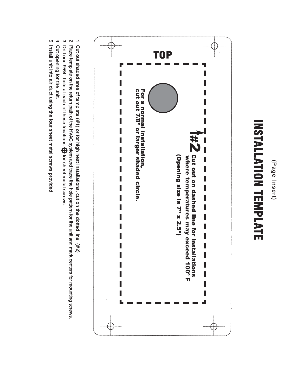
For a normal installation, cut out the 7/8” round opening indicated as #1 on the template. (See page insert)
When installing in an area where temperatures will rise above 100º F (such as attic installations), cut out
the large square area indicated with dashed lines and marked as #2. Center the template on the longitudinal
axis of the plenum, using tape to hold in place. Trace hole pattern for unit and mark centers for mounting screws.
(Figure A)
3. Drill 9/64” holes for sheet metal screws and cut
opening for the unit.
4. Remove the cover from the unit by removing the
top and bottom retaining nuts using a 11/32 size
nut driver.
5. Attach to air duct using the four sheet metal screws provided.
6. Remove germicidal lamp holder (Figure B)
using a 11/32 size nut driver.
7. Slide germicidal lamp into lamp opening.
8. Reinstall lamp holder.
9. Plug in lamp connector to the end of lamp.
Replace and secure cover using the two retaining nuts.
10.
Germicidal Lamp
Holder
(Figure B)
Page 5

WIRING
Plug the unit into an 120 VAC outlet and allow it to run continuously. The ballast is factory
set at 120 VAC. For installations that require 240 VAC locate the 120 / 240 volt power selector on
the ballast and set for the correct voltage. (Figure A) Connect in accordance with local wiring codes.
MAINTENANCE
This maintenance schedule is only a guideline, determined by average conditions. Actual
conditions will dictate the frequency of cleaning and/or replacement of lamps. Do not touch the
glass portion of the lamp with bare hands because oils from the hands can cause “hot spots”
which reduce lamp life. Handle either by the porcelain caps or use a soft cloth. If you
accidentally touch a lamp, wipe it off, using a soft cloth dampened with rubbing alcohol.
CLEANING THE LAMP -
1. Unplug the power cord from the outlet, or disconnect power to the unit.
2. Remove the cover from the unit by removing the top and bottom retaining nuts
using a 11/32 size nut driver.
3. Unplug the lamp connector from the end of the lamp.
4. Remove lamp holder using a 11/32 size nut driver. (Figure B)
5. Remove the lamp by grasping the porcelain cap and extract carefully.
Using a soft cloth moistened with rubbing alcohol, wipe down the lamp.
6.
If there is a large build-up of dust particles, you may wish to use a
can of air first. Always handle lamp by the end caps.
7. Slide the lamp back into lamp opening.
8. Reinstall lamp holder.
9. Plug the lamp connector to the end of the lamp.
10. Replace and secure cover using the two retaining nuts.
11. Plug power cord back into outlet, or restore power to unit.
Recommended interval: 12 months
REPLACING THE LAMP -
Recommended interval: 24 months. Follow above procedure excluding #6.
Please note standard off-the-shelf lamps are not compatible with this unit.
Use of improper lamps will void warranty.
 Loading...