

Page 1

INSTALLATION GUIDE
Horizontal
series
HRV MODEL 8160and MODEL 8220
ERV MODEL 3160and MODEL 3220
Page 2

2
About Us
GeneralAire offers you a complete range of products designed to improve indoor air quality, and
that provides a wide selection of accessories to facilitate installation.
Our vision – To offer a complete range of GeneralAire products that satisfy environmental
concerns.
Whether your needs involve ventilation, purification, humidification or filtration, GeneralAire has
the customized solution for you, with its range of quality products backed by the best warranty
in the industry.
Installation
1. Ventilation needs
2. Types of installation
3. GeneralAire HRV/ERV systems
4. Finding a suitable installation area for the HRV or ERV
5. Installation of the HRV/ERV
6. Rigid duct
7. Insulated flex from unit to outside wall
8. Condensation drain line
9. Devoted electric receptacle
10. Outside fresh air and exhaust air hoods
11. Fresh air and exhaust air grilles
12. Benefits of the DuotrolTMsystem
13. Balancing the unit
Functions and Controls
14. Controls and wiring
Technical Information
15. Troubleshooting
16. Wiring diagram
17. Maintenance
18. Specification and technical information
Peace of Mind
All GeneralAire products are
backed by the best limited
warranty in the industry, for
your peace of mind.
You benefit from a lifetime warranty on
the core, a 10-year warranty (5 years +
5 years prorated) on our ventilation
motors, a 5-year warranty on the
enthalpic core, and a 5-year warranty
on all other components. So you can
breathe easy.
3
3
6
6
7
7
8
9
10
11
12
13
14
15
19
20
21
22
INFORMATION FOR INSTALLERS PAGE
INFORMATION FOR HOME OWNERS AND INSTALLERS PAGE
INFORMATION FOR HOME OWNERS AND INSTALLERS PAGE
INSTALLATION
GUIDE
Page 3
3
Determine your
ventilation needs
installation
How much fresh air do I need? Good air
quality is based in part on the capacity
of the home’s ventilation system.
Usually, the HRV’s or ERVs capacity is
measured in CFM (cubic feet per
minute) or L/s (Liters per seconds) of
fresh air being distributed in the living
space. The room count calculation or the
air change per hour method shows you
how to determine your ventilation needs.
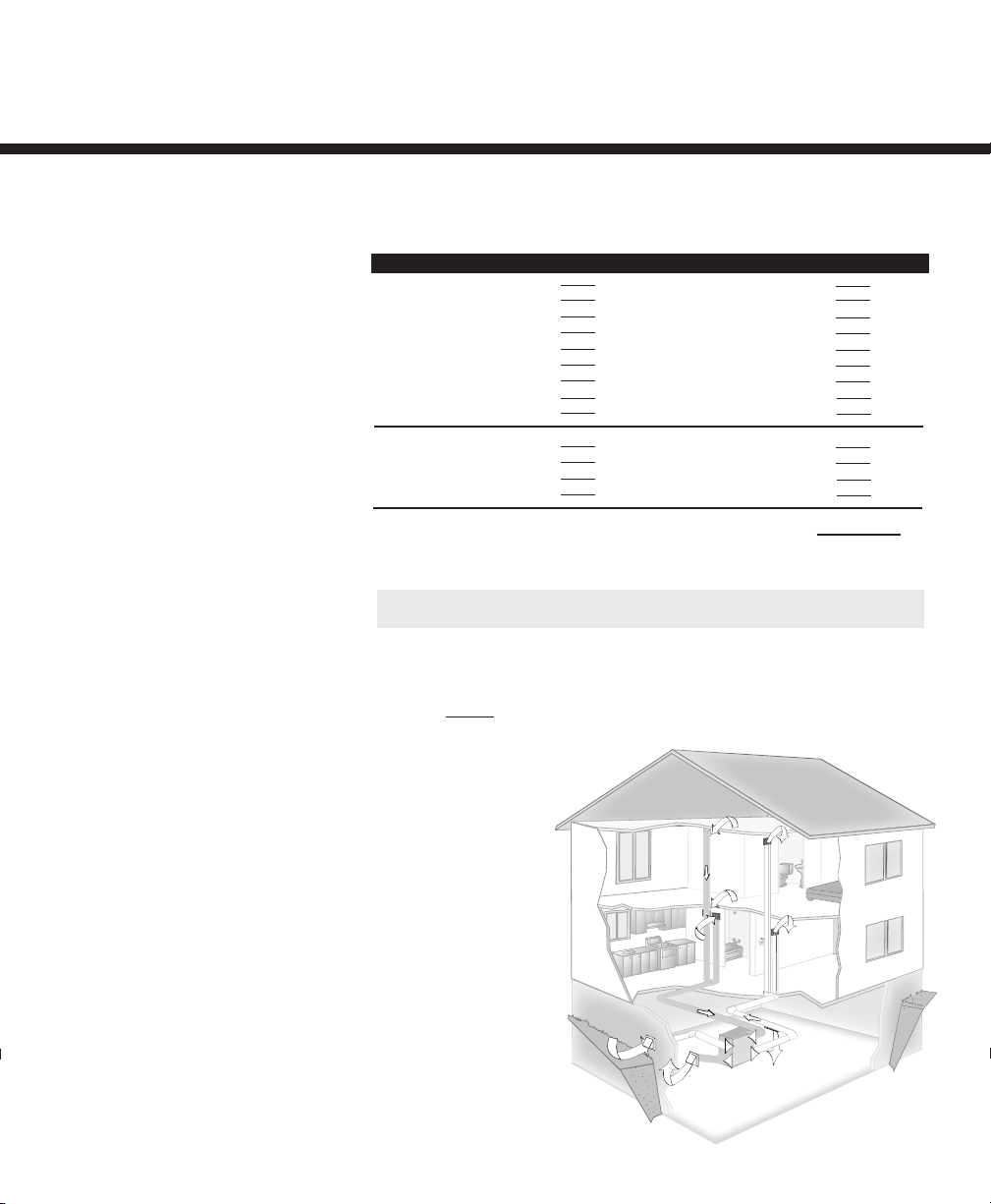
Independent system
installation
This application uses a
devoted duct system for the
supply and the exhausting
of stale air accumulated
in the home.
It is recommended to install
fresh air grilles in all
bedrooms and living areas. Exhaust
the stale air from the bathroom,
kitchen and laundry room.
Independent System
A. Room count calculation
B. Air change per hour method
2. Types of Installation
1.Ventilation Needs
LIVING SPACE
Master Bedroom
With Basement
Without Basement
Single Bedroom
Living Room
Dinning Room
Family Room
Recreation Room
Other
Kitchen
Bathroom
Laundry Room
Utility Room
TOTAL cu ft x 0.35 per hr = total
Take total and divide by 60 to get CFM
Number of Rooms CFM (L/s) CFM Required
x 20 cfm (10 L/s)=
x 20 cfm (10 L/s)=
x 10 cfm (5 L/s)=
x 10 cfm (5 L/s)=
x 10 cfm (5 L/s)=
x 10 cfm (5 L/s)=
x 10 cfm (5 L/s)=
x 10 cfm (5 L/s)=
x 10 cfm (5 L/s)=
x 10 cfm (5 L/s)=
x 10 cfm (5 L/s)=
TOTAL ventilation requirement (add last column)=
1 CFM = 0.47189 L/s
1 L/s = 3.6 m
3
/hr
Example: 25' x 40' house with basement
1,000 sq. ft. x 8' high x 2 (1st floor + basement) = 16,000 cu. ft.
16,000 cu. ft. x 0.35 ACH = 5,600 cu. ft.
5,600 cu. ft./60 minutes = 93 CFM
93 CFM is your ventilation need
Page 4
4
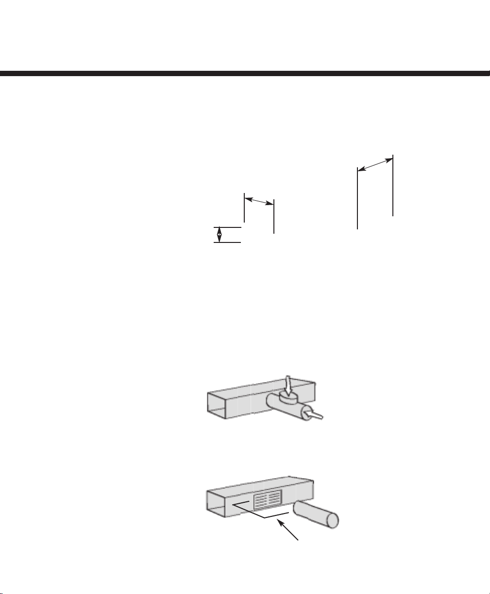
4" to 12" maximum
Indirect Connection - Breathing Tee
Indirect Connection - Return Air Grille
2. Types of Installation (continued)
Exhaust at the
source and supply
in the return
installation
This application uses a
devoted duct system for the
exhausting of stale air accumulated
in the home. The fresh air is dumped into
the return air duct and is distributed thru
the home by the existing supply air
ductwork of the forced air system.
Make sure when using this application that
your fresh air duct connection to the forced
air system return air duct is at least 3' from
the forced air system. You should check
with your local code or the forced air
system’s manufacturer.
Forced Air System
6'
18"
*For minimum distance between return and forced air
system, check with your local building codes and forced
air system manufacturer.
HRV/ERV
From Bathroom or
Kitchen
To living space
There are different practices used to combine HRV or ERV to a forced air system.
3'
Exhaust at the source
A Breathing Tee is a ventilation air supply
duct with an open tee located before the
connection to the return air duct. It allows
the HRV to function without supply air flow
rates being affected by the forced air
system’s fan speed.
Leaving a gap in the ventilation air supply
duct in place of the breather tee is
acceptable but not recommended.
With the return air grille approach, HRV or
ERV ventilation supply air is “dumped”near
a grille (between 4" and 12") in the return
air duct upstream of the recirculation fan.
*See your local code before making an installation.
INSTALLATION
GUIDE
Page 5
5
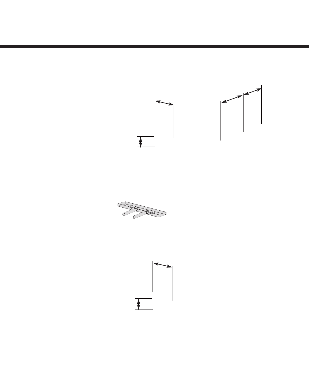
Exhaust and
supply in the return
installation
When using this
application make sure
that there is at least
6' between the fresh
air and exhaust air
connections of the
HRV or ERV in the return
air duct.
Supply air from HRV or ERV must be at
least 3' from the forced air system. Can
be different from a region to an other.
You should check with your local code
or the forced air system’s
manufacturer.
Note
to installer
Fresh air must always be down-stream
from the exhaust air in the return air
duct of the forced air system.
Exhaust from the return
and supply in supply
installation
When using this application make sure
that the Supply air from HRV or ERV is
at least 3' from the forced air system.
Can be different from a region to an
other.You should check with your local
code or the forced air system’s
manufacturer.
2. Types of installation (continued)
Simplified Connection
Forced Air System
6’
18”
HRV / ERV
6’
3’
Exhaust and supply in the return
Forced Air System
6’
18”
HRV / ERV
Exhaust from return and supply in supply
FOR MINIMUM DISTANCE BETWEEN
RETURN AND FORCED AIR SYSTEM
Check with your local building codes and force air system manufacturer.
To living space
Page 6

Installation Kit
Included in the installation kit:
• 4 Collars
• 2 Flexible Vinyl Ducts
• 1 Condensation Drain Line
• 1 Drain Adapter with Nut
• 4 Tie Wraps (30”)
• 16 screws (#10 x 5/8")
• 4 screws (#10 x 1")
• 4 Washers
TIPS
to installer
Removing the core unit will facilitate
your job.
Figure 3.1 Pull out the inserts first then use the straps to lift the unit out of the box.
3. GeneralAire HRV/ERV systems
4. Finding a suitable installation area for HRV or ERV
Figure 3.2 Installation kit is shipped inside the unit.
Figure 3.3 Installation kit.
The HRV or ERV units should be installed in a mechanical room or as close to an outside
wall as possible. This would assure a short run of insulated flexible duct.
The HRV or ERV unit must always be installed in an area where the air is tempered to avoid
freezing of the condensate line. The contractor should install the unit in area that is very
accessible to allow the homeowner easy access for maintenance.
It is very important to install an electric receptacle (115v) near the HRV or ERV, a separate
circuit breaker is also recommended. You should have access to a condensate drain near
the HRV or ERV to avoid the use of condensate pump.
INSTALLATION
GUIDE
6
Page 7

The SPMTMsystem is supplied
with the HRV or ERV to allow
one person mounting of unit.
SPM
TM
attachment system
The entire line of
GeneralAire HRV/ERV
products is designed for
installation by a single
person. “Single Person
Mounting
TM
” will enable you
to save time and effort by offering
you a variable attachment system
and maximizing your basement
space.
TIPS
to installer
If unit is not level, improper
drainage will occur and could lead
to moisture and leakage problems.
TIPS
to installer
It is recommended to use
approximately 16" of flexible duct
(supplied in kit) between the HRV
or ERV and your rigid duct (see
figure 6.1). The flex duct is
mounted the same way to the HRV
or ERV as the insulated flex close
on step 6 (see figure 6.2).
figure 5.1 Place HRV/ERV on a stepladder.
figure 5.2 Attach your four straps to the
floor joist making sure that you attach
thru the washers and the grommets.
figure 5.3 Pull on the middle strap and
gently push upward on the unit. Then
repeat procedure on other side.
figure 5.4 When completing the
procedure make sure that the HRV or
ERV is leveled.
5. Installation of the HRV/ERV
6. Rigid duct
figure 6.1 Mount flex to HRV/ERV.
figure 6.2 Mount flex to rigid duct.
7
Page 8

ISF
TM
collar system
(Patent Pending Technologies)
Quick and simple to install
thanks to our revolutionary
“Insert Slide and FixTM”
collar system.
The “ISFTM” collar system enables you to
manipulate duct within your reach and
then insert the collar to the HRV/ERV
by sliding it in place, for a better and
quicker installation.
TIPS
to installer
To ensure a better installation and to
avoid an undesired bend in the duct,
align the duct with the collar before
securing over the four hooks.
The installer can now beneficiate from the ISFTMcollar system for its flex duct installation to
the unit. Take four collars out of the unit. Insert the flex over the interior flange of the collar.
Make sure that flex is pushed all the way, so the four tabs on the collar hooks on to the flex.
Seal with tie wrap (4 tie wraps supplied with unit). Pull insulation over the interior flange.
Pull vapor barrier over outer flange on the collar and seal with duct tape.
Once insulated flex is attached to the collar, slide collar in keeper section, fixed collar to the
unit with four screws supplied in installation kit.
Insert the threaded drain adapter thru the bottom of the HRV or ERV and hand tighten the
plastic nut supplied with the drain kit.
7. Insulated Flex from Unit to Outside Wall.
figure 7.1 ISFTMcollar system - removable part.
figure 7.2 Insert vinyl duct over the
hooks and seal with a 30" tie wrap.
figure 7.3 Insert insulation inside
the collar.
figure 7.5 Slide collar on the unit.
figure 7.6 Fix and secure with two screws supplied.
figure 7.4 Finish by taping the duct on
the collar.
INSTALLATION
GUIDE
8
Page 9

9
Sloped Drain Pan
drainage system
GeneralAire HRV/ERV units
are equipped with an easy-
access sloped drain pan.
Excess condensation that
might accumulate inside the unit
migrate to the centre of the drain pan
to be evacuated.
8. Condensation Drain Line
Insert the threaded drain adapter thru the bottom of the HRV or ERV and hand tighten the
plastic nut supplied with the drain kit.
Install the condensate line (10 feet included in drain kit). Insert condensate tubing by pushing
clear plastic line over drain adapter. Make condensate trap by looping the clear plastic tubing.
This procedure is to avoid foul odor to enter the HRV or ERV.
figure 8.1 Hand screw the drain adapter
figure 8.2 Insert condensate line.
figure 8.3 Make a loop in condensate line.
figure 8.4 Use a condensate pump if
you don’t have access to the floor drain.
Page 10

INSTALLATION
GUIDE
Insert the power cord on top of the unit.
Press fir
mly to make sure the power cord is
secure.
figure 9.1 HRV/ERV’s Power Cord
It is recommended that the HRV or ERV have
a devoted receptacle with 115v. It is not
recommended to connect unit with an
extension cord. If no receptacle is available
please call an electrical contractor and have
one installed.
figure 9.2 Electric Wall Outlet
9. Devoted Electric Receptacle
10
Page 11

10. Outside Fresh Air and Exhaust Air Hoods
figure 10.1 Locating outside hoods.
72"
18"
figure 10.4 Install outside hoods.
figure 10.2
Insert vinyl duct over the hooks. Fix the
collar on the floor joist.
figure 10.3
Insert insulation inside the collar and
finish by taping the vapor barrier on
the collar.
11
TIPS
to installer
To make your installation easier use our
double collar to install your flex pipe
with the outside hoods (figure 12.2).
TIPS
to installer
We manufacture a wide selection of:
• Insulated flexpipe
• Hoods
TIPS
to installer
Extend the sheet metal sleeve 1.5"
inside the home. Attach GeneralAire
specialty ISF
TM
collar to sheet metal
sleeve.
Page 12

INSTALLATION
GUIDE
12
11. Fresh Air and Exhaust Air Grilles
It is recommended to exhaust the stale air from the bathroom, kitchen, laundry room and
storage room. These areas have been found to be the most pollutant areas in a home.
For the kitchen we recommend the use of GeneralAire’s grease filter grilles.
It is recommended to install fresh air grilles in all bedrooms and living areas. The exhaust air
grilles should be located in the bathrooms, kitchen, laundry room and storage room. Grilles are
usually installed 12" from the ceiling.
GeneralAire grilles are recommended for quiet air diffusion (4, 5, 6 and 8 inches are offered).
The grilles combined with our GeneralAire 4" space saving grille adapters (stack head elbow)
makes for easy and time saving installation.
TIPS
to installer
Note: It is not recommended to
exhaust your clothes dryer, your kitchen
exhaust hood or your central vacuum
cleaner thru your ventilation system.
Save Time and Space...
with GeneralAire’s Stack Head Elbow
available to fit your needs. Ask your
local distributor for more information
on our full range of accessories.
We manufacture a wide selection of:
• Duct
• Stack Head Elbow
• Grilles
figure 11.1 Grille.
figure 11.2 Stack head elbow.
figure 11.3 Insert grille.
Page 13

13
Intermittent:
When the selector switch is in the intermittent position the HRV or ERV will only run
when there is a call for ventilation by any control. At that time the unit will run on high speed until the
condition is satisfied.
Continuous:
When the selector switch is in the continuous position the HRV or ERV will run
continuously on low speed except when there is a call for override by any control.
Off:
When the selector switch is in the off position the HRV or ERV will not come on even if there’s a
call for ventilation by any control.
INTER.:
Selects the exhaust air motor
CONT.:
Selects both exhaust and fresh air motors
OFF:
Selects the fresh air motor
+ Button:
Increase the speed of the selected motor.
- Button:
Decrease the speed of the selected motor.
DuoTrol
TM
balancing system
(Patent Pending Technologies)
Silent and economical... By
reducing motor speed to
balance the unit, you avoid
the noise that would be
produced by balancing
dampers.
In addition, with this
technology the unit will consume
less energy.
Mode
selector
• Intermittent
• Continuous
• Off
Balancing
control
• Intermittent
• Continuous
• Off
• Increase Speed
• Decrease Speed
Acts as a mode selector
Acts as a balancing control
(see instructions)
12. Benefits of the DuotrolTMSystem
figure 12.1 DuotrolTMSystem
The DuotrolTMlets contractor set speed of the motors for balancing purposes
(Exhaust air, Fresh air and Both motors).
GeneralAire’s Duotrol
TM
balancing system (patent pending) is state of the art technology
simplified for quick and easy installation for the contractor’s peace of mind.The Duotrol
TM
serves two purposes.
Page 14

INSTALLATION
GUIDE
TIPS
to installer
As mentioned in the section, the
DuotrolTMSystem has two different
purposes.
1. Mode Selector
2. Balancing Mode
The light indicator shows you in which
mode the DuotrolTMSystem is in.
GREEN LIGHT
Mode Selector
YELLOW LIGHT
Balancing Mode
Using the
Selector Switch
to installer
When on Balancing Mode, the Selector
Switch allows you to choose the motor
you want to set.
Closed Duotrol Cover
1. INTER (Exhaust Motor)
2. CONT (Both Motors)
3. OFF (Supply Motor)
or
Open Duotrol Cover
1. UP (Exhaust Motor)
2. MIDDLE (Both Motors)
3. DOWN (Supply Motor)
13. Balancing the unit
Step 1: Press the (+) and (–) buttons simultaneously until you
see the yellow light. Once the indicator light turns yellow you
are in balancing mode.
Step 2: When in balancing mode the selector switch becomes
the motor selector switch. INTER (Right Motor), CONT (Both
Motors) and OFF (Left Motor)
Step 3: Once the total cfm needed is determined, you can
start balancing the HRV/ERV.Set your fresh air supply by
selecting the “OFF” position on the Duotrol
TM
. Install your
magnehelic gauge and air flow grid in the fresh air duct.
Step 4: Press the (–) button to decrease the cfm or press the
(+) button to increase the CFM.
Step 5: Then perform the same operation on the stale air side
by selecting the “INTER” position on the Duotrol
TM
.
Step 6: The “CONT” position will allow you to adjust the cfm
on both motors proportionately (if necessary).
Step 7: Once this is completed, you have set the high speed
on your HRV/ERV. To lock balancing mode you must press (+)
and (–) buttons simultaneously and release. The indicator light
will turn green to indicate normal operation mode.
Step 8: Once high speed is set and locked, switch to
continuous on the Duotrol
TM
. By using (+) and (-) buttons set
low speed on the HRV/ERV.
Step 9: Select the mode of operation.
(Intermittent, Recirculation or Continuous Ventilation)
figure 13.1 DuotrolTMSystem
figure 13.2 Magnehelic Gauge with Air Flow Grid
figure 15.6 Selector Switch
figure 13.3 Magnehelic Gauge with Air Flow Grid
figure 13.4 Inserting Air flow grid in duct
figure 13.5 Seal Air flow grid in duct with duct tape.
14
Page 15

14. Controls and Wiring
GeneralAire’s DC1allows the homeowner control of the indoor humidity level.
The DC1 is a two wires connection. On the Duotrol
TM
System and the DC1 are
R and G terminal connections on the lower right hand side of the control board.
DC1
DEHUMIDISTAT
Features
• Dehumidistat to select the humidity level
figure 14.1 DC1
figure 14.2 Duotrol
TM
Range of controls
The entire range of GreenThinker
TM
model controls is offered with
features making your
ventilation system simple,
easy to operate and backed
by a 5-year limited warranty.
15
Page 16

INSTALLATION
GUIDE
16
Page 17

17
GeneralAire’s DC4E allows the homeowner control of the indoor humidity level by offering
four selections of operation. The controller allows the homeowner to select the humidity
percentage, fan speed, operation mode and cycles per hour.
The above controller have four wires connection. On the Duotrol
TM
System and DC4E use
R, G, B and W terminal connections on the lower right hand side of the control board.
DC4E
ELITE DEHUMIDISTAT
Features
• Dehumidistat to select the humidity level
• Speed Control (Off, Normal and Reduced)
• Mode Control (Intermittent and Continuous Ventilation)
• Cycles per hour (0/0, 20/40 and 30/30)
• Light On Override
• Maintenance Light Reminder
figure 14.7 DC4E
figure 14.8 Duotrol
TM
CYCLES
0
20/40
30/30
Allows the homeowner to select cycles per hour
Normal operation mode
20 minutes on high speed and 40 minutes on previously set mode of operation
30 minutes on high speed and 30 minutes on previously set mode of operation
MAINTENANCE
Light indicator:
14. Controls and Wiring (continued)
Shows homeowner when HRV or ERV needs to be maintain.
Page 18

INSTALLATION
GUIDE
18
14. Controls and Wiring (continued)
GeneralAire’s TR3 allows the homeowner controls of the indoor humidity level in rooms
were more humidity is produced (Ex. bathroom and kitchen).
The
TR3 allows the homeowner to override the DC Dehumidistat to high speed for a
determined length of time (20min, 40min and 60min).
The
TR3 is a three wires connection. On the low voltage control board use R, G and B
terminal connection on the top right hand corner of the board.
figure 14.9 TR3
figure 14.10 Duotrol
TM
TR3
TIMER CONTROL
Feature
• 20/40/60 minutes exchange
To operate:
Press the PUSH button once,the light indicator will blink one time.
The unit will operate at high speed for 20 minutes.
Press the indicator light until it blinks twice, the unit will operate
at high speed for 40 minutes.
Press the indicator light until it blinks 3 times, the unit will operate
at high speed for 60 minutes.
(Pressing the button gives you the first blink.)
Page 19

19
PROBLEMS
• HRV or ERV not running
• Air is too dry
• Air too humid
SOLUTIONS
• Verify breaker in electrical box
• Verify that dehumidistat or switch on HRV or ERV are
activated to supply power to unit.
• Unplug HRV or ERV verify if controller is wired correctly to
the connection box on the side of the unit.
• Verify low voltage box (Duotrol
TM
)on the unit
• Increase humidity level on dehumidistat.
• Switch ventilation mode from continuous to intermittent
• Install a GeneralAire humidifier
• Reduce the humidity level on the controller.
•Verify if dryer is venting in basement.
•Verify if heating wood is stored in basement.
•Wait for outside temperature to change.
Ex. Summer can be extremely humid.
•Verify balancing of the HRV or ERV.
Peace of Mind
Ensure your comfort in the
years to come by using
GeneralAire systems and
accessories to install any
ventilation, humidification,
purification or filtration product.
Need help? You benefit from certified
customer service ready to guide you in
the installation or operation of your
GeneralAire system.
Call: 1-248-476-5100
15. Troubleshooting
Page 20

INSTALLATION
GUIDE
20
Standard Forced Air
Interlocking Wiring
A relay is normally used when tying a
ventilation system onto forced air
distribution system. Our Duotrol System
is equipped with an internal relay that
will activate the forced air system’
ventilator when there is a demand from
the HRV/ERV. The Duotrol System will
activate the INTERLOCK relay during the
following modes: Continuous, Override,
Recirculation and Defrost. See wiring
diagram.
Alternate Forced Air
Interlocking Wiring
Some forced air system thermostat will
activate the cooling system when tied
using the “Standard forced air
interlocking wiring”.
If you have identify this type of
thermostat you must proceed with the
“A lternate forced air wiring”.
Locating the
Wiring Diagram
to installer
Wiring diagram for the entire line of
professional and furnace models
are placed on the back of each
exhaust motor bracket.
16. Wiring Diagram
Standard Forced Air Interlock Wiring
Alternate Forced Air Interlock Wiring
*Before tying the HRV/ERV to a
forced air system, always refer to
system’s manual or manufacturer.
Page 21

21
FMA
TM
maintenance system
In order to improve air quality
and offer the best possible
air quality in your home,
GeneralAire has developed
one of the first maintenance
service systems in the
industry.The “Filter Maintenance
AdviserTM” will remind you by e-mail
when the filter of your HRV/ERV system
must be replaced, to maximize its
performance and efficiency.
For more information call:
1-248-476-5100
When should I Service my
HRV/ERV?
service and accessories
HEAT RECOVERY CORE UNIT
Once a year or as needed,
vacuum the four surfaces,
let soak in warm water for
three hours, then spray
rinse and let dry.
FILTERS
Four times a year or as needed, vacuum
the filters. Replace filters once a year.
INSIDE THE UNIT
Once a year or as needed, clean the
interior of the unit (walls and drain pan)
with a mild and non abrasive soap. It is
recommended to use products that are
environmentally-friendly.
ENERGY RECOVERY CORE UNIT
Once a year or as needed, vacuum the
four surfaces.
Note
to installer
IMPORTANT : ALWAYS UNPLUG HRV OR
ERV DURING SERVICING
17. Maintenance
figure 17.1 Slide Out the Filters
figure 17.2 Vacuum the Filters
figure 17.3 Slide out the Energy Core
figure 17.4 Wash the Walls of the Unit
Page 22

PROFESSIONAL,DELUXE AND FURNACE MODELS
INSTALLATION
GUIDE
22
Easy Access Door
removable top hinge door
Note
to installer
All GeneralAire products are backed by the
best limited warranty on the market.
GeneralAire reserves the right to modify a
product, without prior notice, whether in
design, colour or specifications, in order to
offer at all times a quality product that is
highly competitive.
Please consult local authorities to find out
whether the installation of electrical
products requires the services of a
certified technician or electrician.
23
7
/
8
"
21
1
/
2
"
18. Specification and Technical Information
Certified Products and Proud Member of These Associations
SPECIFICATIONS
Size
Heat exchanger (L x H x W)
CFM
Type of heat exchanger
Exchange surface
Power consumption
Defrost type
Certification
02280618
23
Unit Housing
20 gauge powder coat steel 20 gauge powder coat steel
Unit Housing
20 gauge powder coat steel 20 gauge powder coat steel
7/8
" x 21
1/2
" x 11
3/8
" 23
7/8
" x 21
1/2
" x 16
1/2
"
"51 x "21 x "21"01 x "21 x "21
022 ot 05061 ot 03
wolf-ssorcwolf-ssorc
104 ft
2
150 ft
2
W 051W 031
tsuahxEtsuahxE
HVI,CCSA
US
HVI,CCSA
US
SPECIFICATIONS
Size
Heat exchanger (L x H x W)
CFM
Type of heat exchanger
Exchange surface
Power consumption
Defrost type
Certification
02230613
23
7/8
" x 21
1/2
" x 11
3/8
" 23
7/8
" x 21
1/2
" x 16
1/2
"
"51 x "21 x "21"01 x "21 x "21
022 ot 05061 ot 03
wolf-ssorcwolf-ssorc
104 ft
2
150 ft
2
W 051W 031
tsuahxEtsuahxE
C
CSA
CSU
CSA
US
8160 11
3
/
8
"
8260 16
1
/
2
"
3160 11
3
/
8
"
3220 16
1
/
2
"
*
 Loading...