

Page 1

Model Elite Steam Humidifiers
User Manual
Manual d’utilisation
Read and Save These Instructions
Lire et Conserver Ces Instructions
Revision 4.0
Manufacturers of Whole House Residential Indoor Air Quality Products.
Humidifiers - Dehumidifiers - Air Cleaners - UV Air Purifiers - Heat/Energy Recovery Ventilators
www.generalfilters.com
Page 2
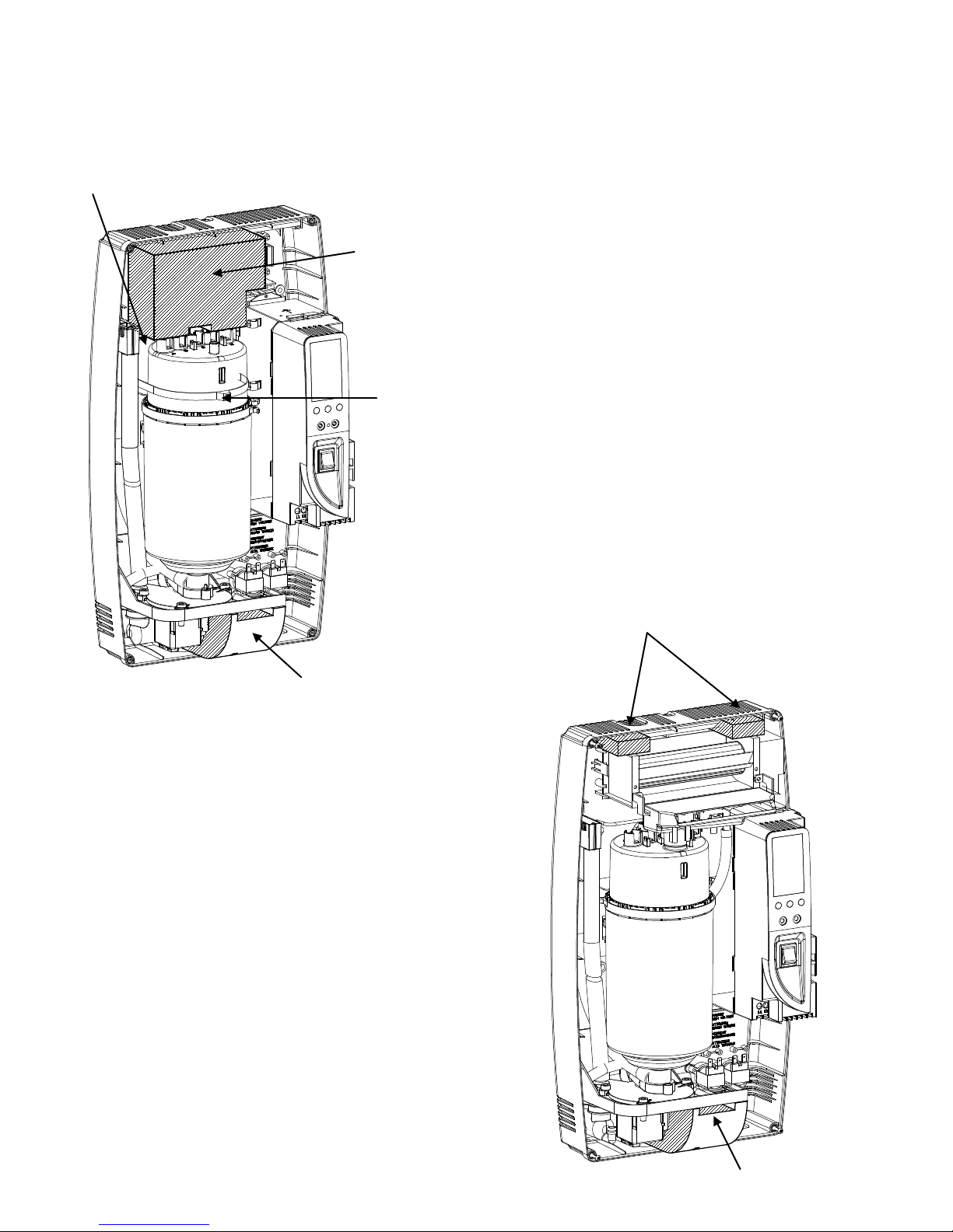
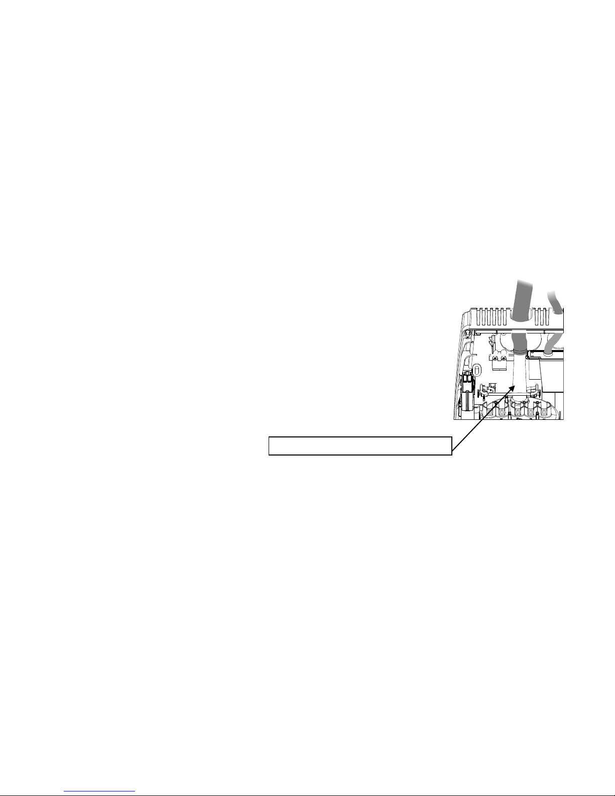
LATCH THE CYLINDER CLAMP
REMOVE BEFORE INSTALLING
REMOVE BEFORE INSTALLING
REMOVE BEFORE INSTALLING
REMOVE BEFORE INSTALLING
REMOVE BEFORE INSTALLING
Warning
If present, remove the following items:
Elite Steam +030222075 Rev. 4.0 – 2 Mar. 2015
1
Page 3
IMPORTANT WARNINGS
BEFORE INSTALLING OR HANDLING THE HUMIDIFIER PLEASE CAREFULLY READ AND F OLLOW THE INSTRUCTIONS
AND SAFETY STANDARDS DESCRIBED IN THIS MANUAL AND ON THE LABELS ATTACHED TO THE Elite Steam.
CAUTION: ALWAYS DISCONNECT THE MAIN POWER
Elite Steam produces non-pressurized steam by means of electrodes immersed in the water contained in the plastic steam
generator cylinder. Electric current passes through the water between the electrodes, heating the water into steam, which is then
used to humidify the air.
The quality of the water used affects the operation of this unit, so the Elite Steam may be supplied with untreated water, as long as
this is drinkable and not softened or demineralized. The water converted into steam is automatically replaced through an electric fill
valve. Periodically, based on the water quality, the unit will also drain some water to dilute the build-up of minerals in the steam
generator. In cases of high water mineral content, an activated carbon filter is series with a particulate filter, no more than 5 microns
is suggested.
This humidifier has been designed exclusively to directly humidify rooms or ducts, using a distribution system. The installation, use
and maintenance operations must be carried out according to the instructions contained in this manual and on the labels applied
internally and externally.
IMPORTANT: BEFORE beginning installation:
• Check for shipping damage to cartons. Mark the shipping waybill accordingly.
• Open cartons and check for any hidden damage. Mark the shipping waybill accordingly.
• Check packing slip to ensure all items have been received. Notify GENERAL FILTERS, INC. of any shortages or damaged
parts. You must notify General Filters, Inc. within 5 working days of any shortages.
CAUTION: ELECTRIC SHOCK HAZARD! The humidifier has components under power inside!
CAUTION: SCALDING HAZARD! The humidifier has hot parts ( 100°C/ 212°F)
WARNING: Install the humidifier out of the reach of children.
The humidifier must be installed in accordance with all local and national standards.
All service and/or maintenance operations must be performed by qualified personnel who are aware of the necessary
precautions and are capable of performing the operations correctly.
Disconnect the humidifier from the main power supply before accessing any internal parts.
The conditions of the environment and the power supply voltage must comply with the specified values listed on the data
label in the humidifier.
All other uses and modifications made to the humidifier that are not authorized by the manufacturer are considered
incorrect, and the manufacturer assumes no liability for the consequences of any such unauthorized use.
Please note that the humidifier contains powered electrical devices and hot surfaces.
The humidifier is made of metallic and plastic parts. All parts must be disposed of according to the local and national
standards for waste disposal.
WARNING: Your humidifier requires water to operate. Do NOT mount it above materials or machinery that could be
damaged if a leak occurs. General Filters, Inc. assumes no responsibility for consequential or inconsequential damage as
a result of any leaks.
BEFORE OPENING OR SERVICING THE HUMIDIFIER!
We wish to save you time and money!
We can assure you that the thorough
reading of this manual will guarantee
correct installat ion and saf e use of the
product described.
Disposal of the parts of the humidifier:
of according to the local sta ndard s on waste disposal.
Elite Steam +030222075 Rev. 4.0 – 2 Mar. 2015
the humidifier is made up of metallic and plastic parts. All parts must be disposed
2
Page 4

CONTENTS
1. HOW THE ELITE STEAM WORKS 4
1.1 B
1.2 C
1.3 C
ASIC OPERATION 4
YLINDER LIFE 5
ALCULATING HUMIDITY LOAD 5
2. MODELS 6
3. INSTALLATION 7
3.1 P
3.2 M
3.3 P
3.4 S
3.5 P
3.6 C
3.7 W
OSITIONING 7
OUNTING 7
LUMBING 9
TEAM DISTRI B U TI O N 10
OWER WIRING 13
ONTROL WIRING 13
IRING CONNECTIONS: 15
4. START-UP 16
4.1 S
4.2 T
4.3 S
4.4 S
TARTUP CHECKLIST 16
HE ELITE STEAM CONTROLLER 16
TARTING ELITE STEAM 16
TARTING WITH A NEW CYLINDER 16
5. OPERATING ELITE STEAM 17
5.1 D
5.2 C
5.3 A
5.4 R
5.5 U
5.6 A
ISPLAYING INFORMATION 17
HANGING THE MAXIMUM PRODUCTION 17
CTIVATING MANUAL DRAIN 17
ESETTING THE HOUR COUNTER 17
SING THE GFX3 HUMIDISTAT 18
LARMS 18
6. TROUBLE SHOOTING 19
7. MAINTENANCE 20
7.1 P
7.2 C
7.3 R
ERIODIC CHECKS 20
YLINDER MAINTENANCE 20
EPLACEMENT PARTS 21
8. TECHNICAL SPECIFICATIONS 22
9. LIMITED WARRANT Y 23
Elite Steam +030222075 Rev. 4.0 – 2 Mar. 2015
3
Page 5
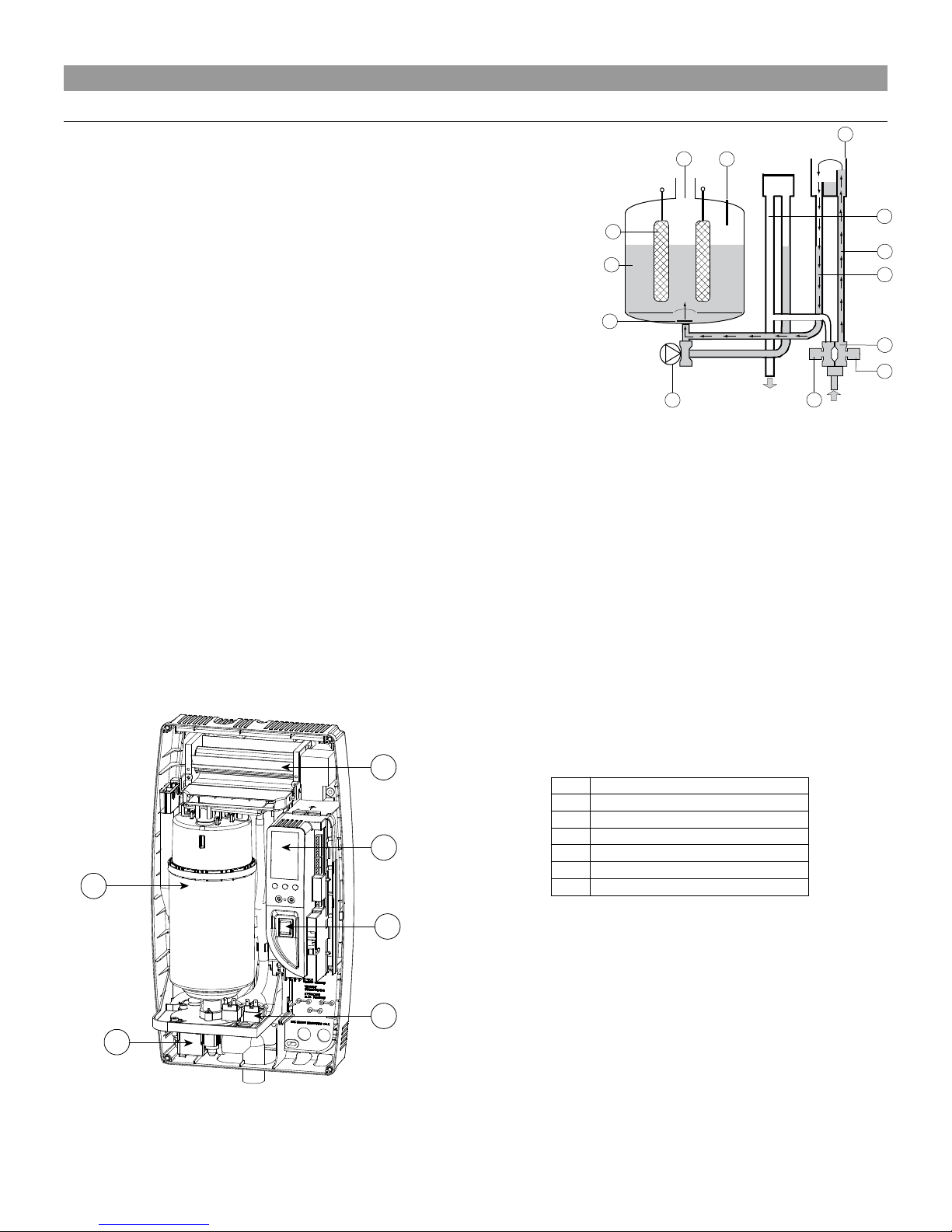
No.
Description
A
Steam generator cylinder
B
Room blower/manifold (optional)
C
User interface/display
D
On/Off, SET buttons
E
Fill & tempering valves
F
Drain pump
Tab. 1.a
Fig. 1.a
HL
DP
DT
EVF
8
9
3
13
6
10
2
4
1
11
7
12
5
A
F
B
C
D
E
1. HOW THE ELITE STEAM WORKS
1.1 Basic Operation
Elite Steam is an electrode humidifier. It produces steam for humidification by
passing electric current through the water between metal electrodes in the
plastic steam generator cylinder. There are no heating elements. Steam output
is directly proportional to the conductivity of the water, and the amount of
electrode immersed in the water.
On a call for humidity, the Elite Steam controller will open the water fill valve (1)
and allow water to enter the cylinder. A flow restrictor (4) prevents the unit from
filling too quickly or with too much pressure. The water flows up the fill tube (2)
and into the fill cup (3). W ater then flows over the dam in the f ill cup (3), which
creates a 1” air gap to prevent backflow of contaminated water into the feed
lines, and through the fill tube (6) and into the bottom of the steam cylinder (5).
Any backflow or overflow of water travels through the overflow hose (13) to the
drain.
As the water fills the cylinder, it will reach the electrodes (7) and current will
begin to flow. As the water continues to fill the cylinder, the current will
increase, and this is monitored by an amperage transformer connected to one of the power wires and located on the
electronic controller. When the desired current is reached, the fill valve will close (1) and the water will then begin to warm
and produce steam. If the water reaches the cylinder full probes (9) or if current rises too much, the drain pu mp (11) will be
activated to drain awa y some water and reduce the current flow to acc eptable levels. Note that, any time the drain pump is
activated, the tempering valve (10) will be opened for tempering the hot drained water down to 140 degrees F / 60 degrees C
in accordance to local and national standards.
Periodically, based on the incoming water conductivity, the unit will run drain pump (11) and drain some water to reduce the
mineral concentration. Every 120 hours the unit automatically drains to remove mineral sediment on the bottom of the
cylinder. A strainer (12) in the cylinder helps to prevent mineral debris from jamming the drain pump (11).
In case Elite Steam remains powered but idle, i.e. without producing steam, for more than 72 hours (3 days), the cylinder will
be emptied to not have stagnant water inside.
If there is no water in the cylinder, there will be no current flow and no steam production. The electrodes do not burn out, but
they will eventually become completely coated with mineral and the cylinder will then need to be replaced. Cleaning cylinders
may cause electrode damage, therefore voiding its warranty. See 7.2.2 maintenance section on page 21.
Fig. 1.b
Elite Steam +030222075 Rev. 4.0 – 2 Mar. 2015
4
Page 6

Table 1.2 Pounds of Moisture / Hour / Cubic Foot *
Indoor Air
Temp °F
35%
Indoor RH%
40%
45%
50%
68
0.00015
0.00018
0.00021
0.00024
70
0.00017
0.00020
0.00023
0.00026
72
0.00019
0.00022
0.00025
0.00028
100%
20%
Fig. 1.c
1.2 Cylinder Life
1.2.1 Basics of the Steam Cylinder
The Steam Cylinder is the engine of the humidifier. As the humidifier operates water is evaporated and minerals are left
behind. Much of these minerals are removed through the c ylinder drain. Some are depos ited on the walls of the cylinder and
the cylinder electrodes. When a lower section of the electrodes develop a thick coating, the water level is raised to expose
clean electrode surface. Eventually minerals cover the electrodes’ entire length with a thick coating and little electrical current
can pass between them resulting in poor steam output. The humidifier can sense the low amperage and will display the E6
Cylinder Exhausted error code. There are several factors that influence cylinder life.
1.2.2 Water
Characteristics of water influence cylinder life and can vary greatly from place to place. Total mineral content of the water is
important. Equally important is what minerals are present in the water. Most water conditions result in flaky scale that
eventually fills the bottom of the cylinder until it can no longer function. Water with high silica content can result in a thin
glass-like coating on the electrodes that is highly insulating resulting in shorter cylinder life. Only cold wa ter is to be used.
Water conductivity that is not matched to the correct cylinder will shorten cylinder life.
1.2.3 Water Filtration
Typically additional filtration of the incoming water supply is not necessary. If, however, mineral content is known to reduce
cylinder life excessively or if cylinder life proves insufficient then water filtration c an be added. In most cas es the addit ion of a
two element water filter can improve cylinder life. The filter should contain an activated carbon element and a particul ate filter
element rated for 5 microns or less. Micron is a size measurement. The filter system should have a flow rate of at least 2
gpm. The activated carbon will absorb much of the mineral content while the particulate filter will catch any granular material
or sediment. It is important to remember that the increase in cylinder life will be accompanied by the need to replace filter
elements with each cylinder change.
1.2.4 Humidity Load and Cylinder Life
Humidity load demands have an effect on cylinder life. Normal installations where humidity capacity is properly sized require
only intermittent periods where full humidifier capacity is required. This allows the water level in the cylinder to be increased
only as electrode segments become insulated. This tends to maximize cylinder life.
Extraordinary installations that require constant operation at full capacity reduce cylinder life. The water level in the
cylinder is, on average, much higher, and the electrodes become completely insulated mo re quickly. Installations like this
may result in cylinder life of less than 1000 hours.
The importance of providing adequate humidifier capacity should not be underestimated.
1.2.5 Maximum Production
Another factor affecting cylinder life is the maximum production setting. A higher production
rate will result in a shorter cylinder life. For this reason DS-25 and RS-25 units are preset from
the factory at 70%. Further reductions in Maximum Production will extend cylinder life.
See Figure 1.c.
1.2.6 Structures Under Construction
In high end construction projects, humidification is often required while the structure is being finished. Humidification is
necessary to protect and stabilize wood floors, trim and decoration. Humidification load, however, in an unfinished structure
may be five to eight times higher than when finished. Elite Steam humidifiers may be operated while construction is underway
but, reduced cylinder life is to be expected and budgeted for. Good practice dictates that the steam cylinders also be
replaced once the project is complete.
1.3 Calculating Humidity Load
1.3.1 Steps to Determine Humidity Load
*Based on .5 air changes per hour.
Total Square Footage
x Average Ceiling Height
x Factor From Table 1.2
x 1.05 for each Fireplace
Humidity Load in lbs./hour
x 2.88 convert to gallons/day
Gallons per Day Humidity Load
Cylinder
Life
* Based on .5 air charges per hour.
Elite Steam +030222075 Rev. 4.0 – 2 Mar. 2015
5
Page 7
PART NUMBER
DESCRIPTION
PARTS INCLUDED
RS 15P
Fig. 2.b
Room steam discharge, 15 gallons
per day (5.5 Lbs per hour) 115-120v
Complete Humidifier. GFX3 humidistat, code valve, water fill
connector, water supply tubing
RS 25
Fig. 2.b
Room steam discharge, 35 gallons
per day (12 Lbs per hour) 220-240v
Complete Humidifier. GFX3 humidistat, code valve, water fill
connector, water supply tubing
DS 15P
Duct steam injection 15 gallons Humidifier only,
hour) 115-120v
Humidifier only, Kit select ion r equir ed
Fig. 2.a
per day (12 Lbs per hour) 220-240v
Kit selection required
DMNKIT
Duct mount kit
8 ft. steam hose, nozzle, GFX3 humidistat, code valve,
tubing, air proving pressure switch.
wall sleeve with 120v blower and grille pkg.
RMB 3 5
Remote mount blower
12 ft. steam hose, GFX3 humidistat, code valve, condensate
wall sleeve with 240v blower and grille pkg.
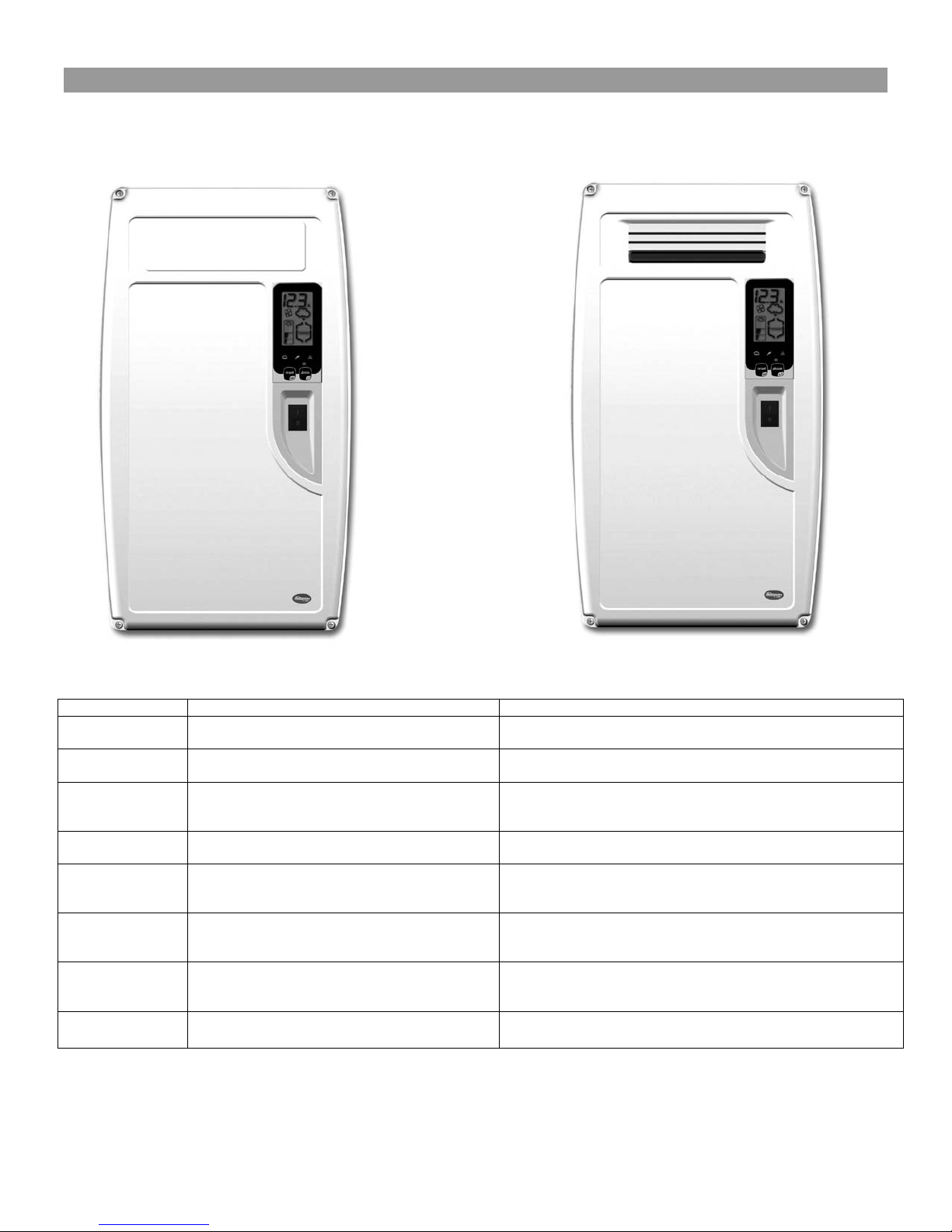
2. MODELS
There are two basic models available in two voltages. Duct models require selection of an additional kit.
Duct Steam Injection Room Steam Discharge
Fig. 2.a
DS 25
(not shown)
RMB 1 5
(not shown)
(not shown)
EDMK4
(not shown)
Elite Steam +030222075 Rev. 4.0 – 2 Mar. 2015
Kit selection requ ired per day (5.5 Lbs per
Duct steam injection 35 gallons
Remote mount blower
kit for DS 15
kit for DS 25
Economy Duct mount kit 4 ft. steam hose, nozzle, 5 ft. condensate hose, fill connector,
Fig. 2.a Fig. 2.b
MODEL LIST
Humidifier only,
water fill connector, condensate hose, water supply
12 ft. steam hose, GFX3 humidistat, code valve, condensate
hose, water fill connector, water supply tubing, and thru-the
hose, water fill connector, water supply tubing, and thru-the
air proving pressure switch (Humidistat not included)
6
Page 8
3. INSTALLATION
Millimeters
Inch
A
(150 mm)
6”
B
(150 mm)
6”
C
(150mm)
6”
D
(150 mm)
6”
E
(600 mm)
24” F max. 0.2°
Tab. 3.a
Fig. 3.a
Duct Steam Injection
C
D
Fig. 3.b
Millimeters
Inch
A
150 mm
6”
B
1800 mm
72”
C
1800mm
72”
D
600 mm
24”
Tab. 3.b
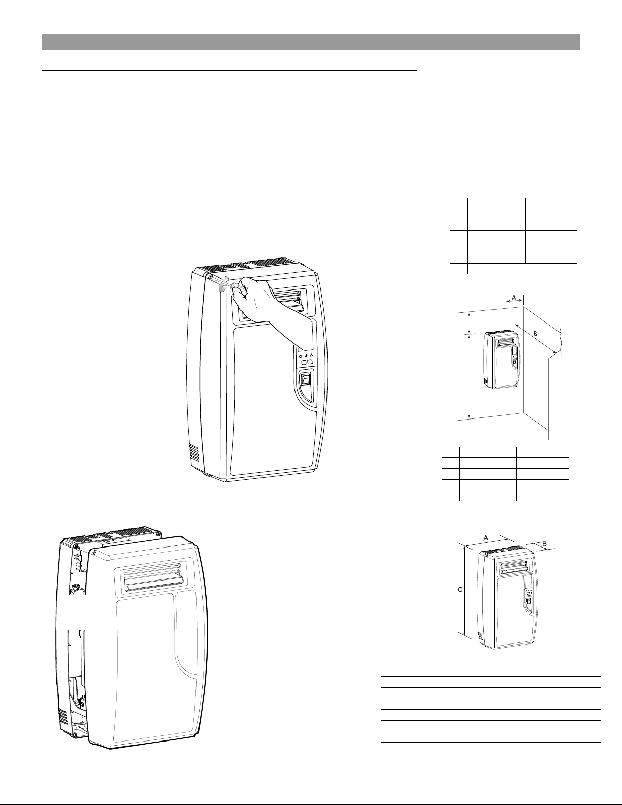
Room Steam Discharge
Millimeters
Inch A 341 mm
13.5“
B
204 mm
8.1“
C
600 mm
23.7“
Kilograms
Pounds
Weight empty
8kg
18 lbs
Weight packaged
10kg
22 lbs
Weight i nstalled with water
12kg
26 lbs
Unit Dimensions: Duct and Room Units
Fig. 3.c
3.1 Positioning
The Elite Steam has been designed for wall mounting and, since it is an atmospheric
steam humidifier, should be placed close to the point where the steam will be used, to
minimize the steam hose length (and the amount of condensate). Certain clearances
must be maintained around the unit for safety and maintenance.
3.2 Mounting
3.2.1 Removing the front cover
The front cover is secured by four screws located at the four corners of the unit. Use a
Phillips head screwdriver to remove the four cover screws. Then simply pull the front cover
away from the back part of the unit. Return it in reverse order.
Be careful not to over-tighten the screws.
Fig. 3.d
Elite Steam +030222075 Rev. 4.0 – 2 Mar. 2015
Fig. 3.e
Tab. 3.c
7
Page 9
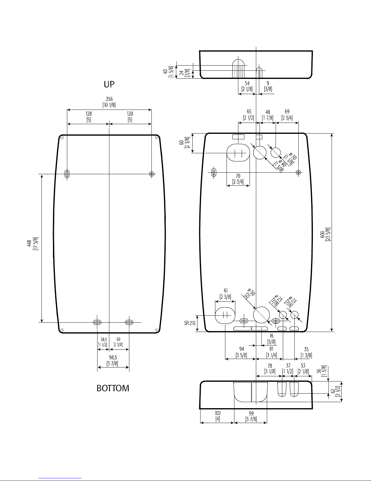
3.2.2 Fastening to the wall
Drill the wall according to the drilling template supplied; then secure Elite Steam firmly to the wall using the screws and
anchors supplied.
Elite Steam +030222075 Rev. 4.0 – 2 Mar. 2015
Fig. 3.f
8
Page 10
3.3 Plumbing
Hydrogen ions (pH)
7 8.5 Hydrogen ions (pH)
7 8.5
Specific conductivity (R,20°C)
μS/cm
300
Specific conductivity (R,20°C)
μS/cm
125
500
Dry residue at 180°C
mg/l
(*)
(*) Dry residue at 180°C
mg/l
(*)
(*)
Total hardness
mg/l CaC³O
150
400 Total hardness
mg/l CaC³O
0
200
Temporary hardness
mg/l CaC³O
=
200 Temporary hardness
mg/l CaC³O
=
150
Iron + Manganese
mg/l F e + Mn
=
0.2 Iron + Manganese
mg/l F e + Mn
=
0.2
Chlorides
ppm Cl
=
30 Chlorides
ppm Cl
=
20
Chlorides
mg/Si2O
=
20 Chlorides
mg/Si2O
=
20
Chlorine residue
mg/l Cl-
=
0.2 Chlorine residue
mg/l Cl-
=
0.2
Calcium sulphate
mg/l CaS4O
=
100 Calcium sulphate
mg/l CaS4O
=
60
ELITE STEAM models
Conductivity μS/cm
Steam Cylinder
DS25, RS25, DS25LC, RS25LC, DS35, RS35
300-1250
35-14
DS25, RS25, DS25LC, RS25LC, DS35, RS35
125-500
35-15
DS15P, RS15P, DS15, RS15
125-1250
15-14
DS20A, RS20A
300-1250
20-14A
DS20A, RS20A
125-500
35-14
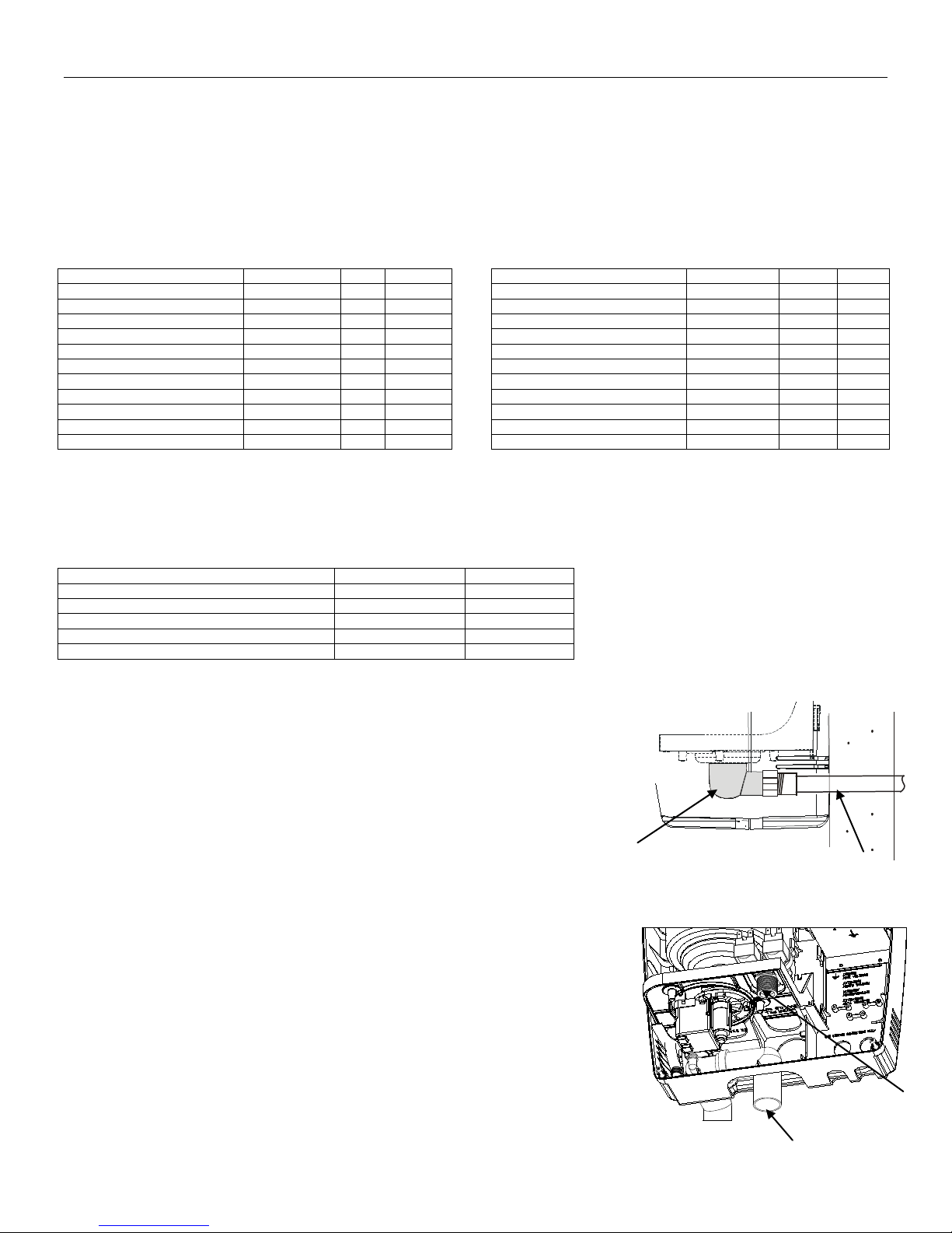
Fill valve and filter
Fig. 3.g
Extension tube
Water drain outlet
3.3.1 Water Characteristic Requirements
The humidifier must be supplied with water with the following characteristics:
• pressure between 20psi and 110psi or 0.1 and 0.8 MPa (1 and 8 bar)
• temperature between 33°F and 104°F or 1°C and 40°C
• flow-rate minimum of 0.45 L/min or 0.21gpm
• hardness no greater than 40°fH (equal to 400 ppm³ of CaCO), conductivity: from 125 to 1250 μS/cm
• absence of organic compounds
• the characteristics of the water of supply must fall within the following limits:
LIMIT VALUES FOR LOW SALT CONTENT WATER LIMIT VALUES FOR LOW NORMAL WATER
Units Min Max Units Min Max
Total dissolved solids (c R) mg/l (*) (*) Total dissolved solids (c R) mg/l (*) (*)
Tab.3.d Tab.3.e
(*) Values dependent on the specific conductivity: in general: cR~=0.65*σR, 20°C; R180~=0.9*σR, 20°C
Note: There is no relationship between the hardness and conductivity of water.
Water Conductivity must be matched by specifications of the steam cylinder. Check or know the water conductivity of
the proposed site before installation. Replace the steam cylinder before startup if not correct. See Table 3.f right.
Tab.3.f
The following water types are not acceptable:
1. Softened water as this will lead to foam, electrode corrosion and greatly shortened
cylinder life.
2. Water containing disinfectants or corrosion inhibiters, as these are potential irritants.
3. Industrial water, boiler water or water from cooling circuits.
4. Any potentially chemically or bacteriologically contaminated water.
5. Heated water.
3.3.2 Water Supply Connection
We recommend the connection between the fill valve and the water supply line by a
soft poly hose capable of absorbing the water hammering in order to avoid damage to
the fill valve itself. The water line may be routed through the back or through the
bottom of the unit. With poly tubing, a tubing support must be used to prevent tubing
collapse and leaks. The fitting then threads onto the fill valve inlet located on the
bottom of the humidifier using a 3/4” G connection. Note that there is a strainer built
into the fill valve fitting underneath the unit, which will require periodic
cleaning, so be sure to allow clearance for access.
9
Elite Steam +030222075 Rev. 4.0 – 2 Mar. 2015
Fig. 3.h
Water drain
Page 11
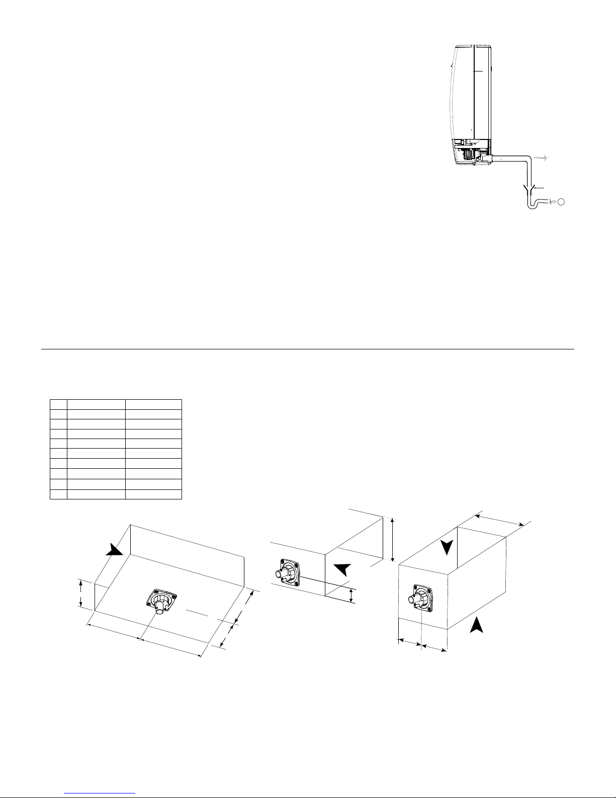
3.3.3 Water Drain
Airflow 1000 cfm min.
Airflow
Min 8”
Height >8”
=
=
Airflow
1000 cfm min.
1/3 Height
Airflow
1000 cfm min.
=
=
8” min
24” min
Upstream
36”min
Downstream
Millimeters
Inch
B
50 mm
1.96”
C
56 mm
2.20”
E
100 mm
3.93”
F
G
22 mm
0.86”
H
∅ 30 mm
∅ 1.18”
I
12 or 22 mm
0.47 or 0.87”
Fig. 3.j
Important: Do NOT install into duct that has interior insulation.
Air Brake
Figure 3.h.2.
The Elite Steam also requires a connection to a drain. The drain line may be routed out the
back or bottom of the unit using the included angle fitting. The drain line can be 1-1/4” PVC,
CPVC or polypropylene. The drain line is not glued or otherwise attached to the humidifier so
it must be supported by itself. A coupling should be used. The Elite Steam includes a drain
tempering valve that runs whenever the drain pump runs and flushes cool water into the drain
line to insure the drain water temperature never exceeds 60°C or 140°F.
The drain water characteristics are:
• Drain Flow Rate – See Technical Specifications (Section 8 / pg 24)
• Connection 32mm or 1 1/4”
• Temperature 60°C or 140°F
min. 5°
NOTE: Drain line must be trapped under the unit to prevent flash steam from condensing in
4
the unit cabinet, as seen in figure 3.h.2.
3.3.4 Drain Connections
When using a rear outlet drain passing through drywall, we suggest using a 1 1/4” extension tube type SJ (see Fig. 3.f).
When using a bottom outlet drain, attach the included 90° fitting to the drain outlet. The drain outlet may be rotated. Then
connect a 1 1/4” trap adaptor to connect to drain pipe.
IMPORTANT WARNING: The drain pipe must be free without back pressure. We recommend an external anti-flooding
device not supplied to protect from faults of external hydraulic circuits.
3.3.5 Condensate Pump
When using a Condensate Pump, ensure pump selected is capable of handling 7.0 GPM for up to 10-15 seconds.
3.4 Steam distribution
3.4.1 Duct steam injection (Additional kit required)
The maximum allowed duct static pressure is 2 in WC.
The Elite Steam duct injection models include a plastic duct injection nozzle. See Fig. 3.i
5
A 31.5 mm 1.24”
D 57.5 mm 2.26”
∅ 8 mm ∅ 0.31”
∅
∅
Fig. 3.i
Important: Do NOT install into duct that has interior insulation.
Elite Steam +030222075 Rev. 4.0 – 2 Mar. 2015
10
Page 12
3.4.2 Duct Distri bution (Additional kit required)
If a duct steam distribution nozzle is to be used, select an accessible location on the duct, allowing at least 36” of straight duct (no
elbows or obstructions) after the point where the nozzle will be installed and the clearances can be maintained as per the following
drawings. See Fig.3.j To mount the steam nozzle, cut or drill a 2-1/2” hole in the duct. Apply caulk to the mounting plate of the
nozzle. Attach the nozzle to the duct using 4 #10 sheet metal screws (supplied). Nozzle must be level or vertical with condensate
outlet to the bottom.
IMPORTANT: Allow 1 M (3 feet ) of straight duct downstream of the distributor pipes and no z z les for absorption of the steam.
Always allow 0.6M (2 feet) of straight duct upstream of the distributor pipes for evaporation of the steam. Turbulent air flow may
require longer lengths
.
Optional stainless steel duct distributor pipe:
Fig. 3.j
To install the distributor pipes:
1. Cut a round hole in the side of the duct to match the steam pipe and condensate return.
2. Apply silicone sealant to the mounting plate and inser t the pipe through the hole and secure it with
sheet metal screw s. See F ig. 3.k
3. Connect the steam and condensate hoses using the hose cla mps suppl ied.
(Note: end support bracket supplied only with 36” and longer distributors.)
3.4.3 Return Condensate Connection
The return condensate hose from the nozzle, etc. must be trapped. Coil the hose into a vertical loop
and secure it below the nozzle, etc. This trap prevents steam from being released into the cabinet.
The hose end may be run through the knockout at the top of the humidifier and be inserted into the
hole located on top of the fill cup. The hole may be enlarged to suit. See Fig.3.l.
25-12 STEAM CYLINDER HOSE ADAPTER
Fig. 3.l
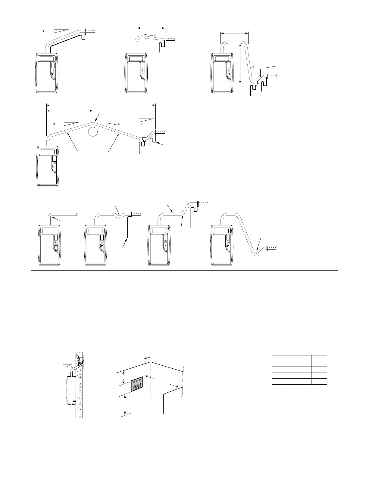
3.4.4 Steam Hoses
IMPORTANT WARNING: NINETY PERCENT (90%) OF ALL OPERATION PROBLEMS ARE CREATED BY IMPROPER STEAM
PIPING FROM THE HUMIDIFIER UNIT TO THE DUCT DISTRIBUTOR PIPES.
To avoid these problems, remember one simple fact when running the steam hose: steam naturally flows up hill, and condensate
naturally flows downhill. Run the steam hose or piping to avoid any kinks, sharp elbows, or low spots that could collect or restrict the
flow of steam to the distributor pipe, or the flow of condensate back to the humidifier. Support the hose adequately to avoid sags.
The following diagrams are to provide you with some guidelines. If you have a situation you are unsure of, please contact the factory
for instructions .
Elite Steam +030222075 Rev. 4.0 – 2 Mar. 2015
11
Page 13
20%
YES
NO
≥20%
A
C
B
D
Millimeters
Inch A 150 mm
6”
B
1800 mm
72” C 600 mm
24” D 2100 mm
84”
Fig. 3.n
IF NO TRAP
1,5 m (5 FT max.)
5%
WITH TRAP
1,5 m (5 FT max.)
IF NO SLOPE
20%
0,9 m (3 FT max.)
3 m (10 FT max.)
1,5 m (5 FT max.)
20% 20%
SUPPORTED STEAM HOSE
AND/ORCOPPER PIPE
NOTES:
• SLOPEPIPING UPIN DIRECTION OF STEAM FLOWAT 20% OR GREATER, WHICH MEANS 65,5mm x305mm (2 1/2” PER FOOT);
• SLOPEPIPING DOWN IN THE DIRECTION OF STEAM FLOWAT 5% OR GREATER, WHICH MEANS 20mm x 305mm (3/4” PER FOOT);
• MAX. LENGTH OF RUBBER STEAM HOSE IS 3 m (10 FT).
• HEIGHT OF P-TRAPSMUSTBE GREATER THAN THE D UCT STATIC PRESSURE.
NO SLOPE
KINKED
GENTLE BEND
OBSTRUCTION
SAG
5%
NO TRAP
DRAINS
P - TRAP
NOTE: HEIGHT OF TRAPSMUSTBE GREATER
THAN THE DUCT STATIC PRESSURE
NO SLOPE
UNDRAINED
ELBOW
TYPICAL INSTALLATION
WHEN UNIT IS ABOVE
THE DISTRIBUTORPIPE
DRAINS
UNDRAINED
ELBOW
NO DISTRIBUTION
PIPE DRAIN
Fig. 3.m
IMPORTANT: Maximum length of rubber steam hose is 4m (12 feet.). Insulated copper tubing may be up to 6m (20feet) in
length. In all cases, minimize sharp bends and elbows. Use 2 - 45° elbows instead o f 90°s.
Hose inner diameter = 7/8” (22 mm); Hose outer diameter = 1-1/4” (30 mm).
3.4.4 Remote Mount Blower
Remote Mount Blowers, are used to distribute the steam directly into the room. The drawings show the minimum recommended
distances to avoid the flow of humidified air from coming into direct contact with persons, lights, electrical appliances, and surfaces
before the steam has been totally absorbed by the environment. For further details on the assembly, the electrical connections and
the use of a Remote Mount Blower, please refer to the specific instruction manual.
Elite Steam +030222075 Rev. 4.0 – 2 Mar. 2015
Tab. 3.g
12
Page 14
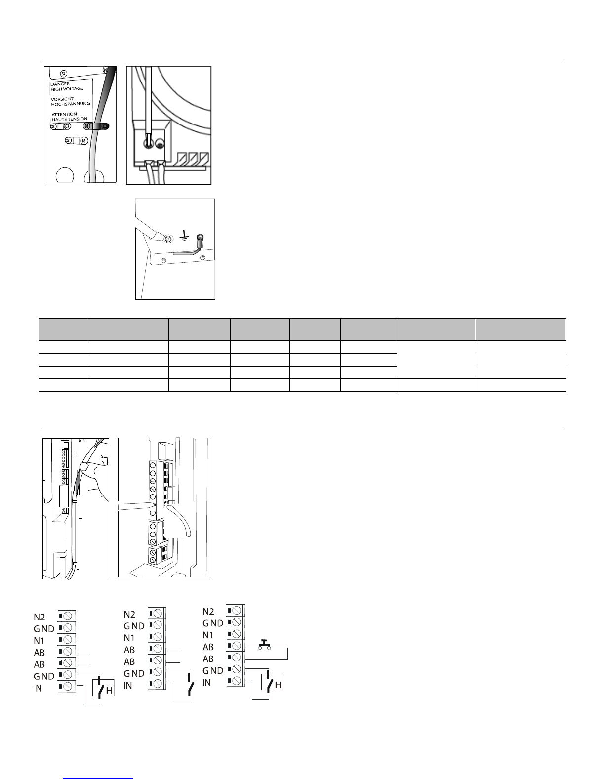
Fig. 3.o
Fig. 3.q
L1 L2
Fig. 3.r
Fig. 3.t
Fig. 3.u
Fig. 3.v
3.5 Power wiring
Check that the power supply voltage to be connected matches the value indicated on
the rating plate inside the electrical panel.
Insert the power and ground connection cables into the ele ct rical panel co mpart men t
using the strain reliefs supplied, and connect to the terminals. An external fused
disconnect must be installed. See Fig. 3.o
All wiring must be in accordance with local, state and national electric codes.
NOTE: to avoid unwanted interference, the power cables should be kept separate
from any control wiring.
NOTE: Tolerance allowed on main voltage =-15% to +10%.
Fig. 3.p
Connect power wires to the power terminal block located at the bottom left of the
control module, polarity does not matter. See Fig. 3.p
Connect the ground wire to the unit’s chassis ground, located just behind the power
wiring terminal block. See Fig. 3.q
Model
DS15 110V ac 50/60Hz 5.5 2.5 1.80 16.40 AWG10
RS15 110V ac 50/60Hz 5.5 2.5 1.80 16.40 AWG10
DS35 230V ac 50/60Hz 12 5.4 3.89 16.95 AWG10
RS35 230V ac 50/60Hz 12 5.4 3.89 16.95 AWG10
Power supply
(single phase)
Steam Output
(lbs/hr)
Steam Output
(kg/h)
POWER
(kW)
CURRENT
(A)
EXTERNAL
POWER WIRES
3.6 Control wiring
Elite Steam allows connection of any simple or automatic humidistat, and safety
devices such as high-limit humidistat, air flow proving switch, and remote on/off.
The humidifier is operated by the closing of a mechanical humidistat H, or by the
closing o f a voltag e-free remote contact, or alternatively by a combination of both. The
most common is a combination of a humidistat and pressure switch. The diagrams
in the figures show the connections to be made on the terminal block, in case of:
Fig. 3.u Operation performed by a simple enabling contact;
Fig. 3.t Operation controlled by an external mechanical humidistat;
Fig. 3.v A combination of both humidistat and pressure switch (most common).
Contact AB-AB:
• closed: humidifier enabled to produce steam (production starts when humidistat
closes);
• open: steam production is immediately stopped.
The remote on/off contact is usually a series of external potential-free contacts that
Fig. 3.s
enable the humidifier to produce steam when all of them are closed, indicating the
duct/AHU is ready to accept steam. Connect the 12500 Pressure
Switch NO and C terminals to the AB-AB contacts.
For example,
• fan contact closes when fan is running;
• downstream cooling coil contact closes when coil is off;
• etc.
Contact IN-GND:
• closed: steam production starts if contact AB-AB is closed
• open: steam production is stopped after 5 sec.
EXTERNAL FUSE (A)
OR BRAKER
25
25
25
25
Elite Steam +030222075 Rev. 4.0 – 2 Mar. 2015
13
Page 15
N2
GND
N1
AB
AB
GND
IN
NO
C
NC
C
NO
GND
24V
AC L
AC N
HUM
SNSR
OUTDOORTEMP. SENSOR
(not used in manual mode)
Elite Steam
ON DIP
1 2 3 4
ADCD
DIP SWITCH SETTNGS
FOR HUMIDISTAT ONLY OPERATION
ON
OFF
OFF
ON
Fig. 3.w
Fig. 3.x
3.6.1 Connect the GFX3 Humidistat for On/Off Operation:
1. Remove the humidistat from the base, squeeze the louvered base at the top and bottom. To remove the humidistat from
the wall, lift up on the humidistat and pivot top away from wall.
2. Before wall mounting, please remove the black foam gasket.
3. Before return air duct mounting, please remove the breakout piece.
4. If return air duct mounting, route wires between humidistat and base.
5. Mount the sensor outside the house. Do not mount on South side of the house or in direct sunlight. Place at least 4 feet
away from any exhaust vent. If in air intake, place 1 foot or closer to outside wall. Place at least 6” higher than possible
snow. Do not route sensor wire near high voltage wires.
6. Connect the GND-IN terminals on the humidifier to the HUM terminals on the GFX3 Humidistat. Connect the GND-24V
terminals to the ACL-ACN terminals on the GFX3 Humidistat. see Fig.3.x
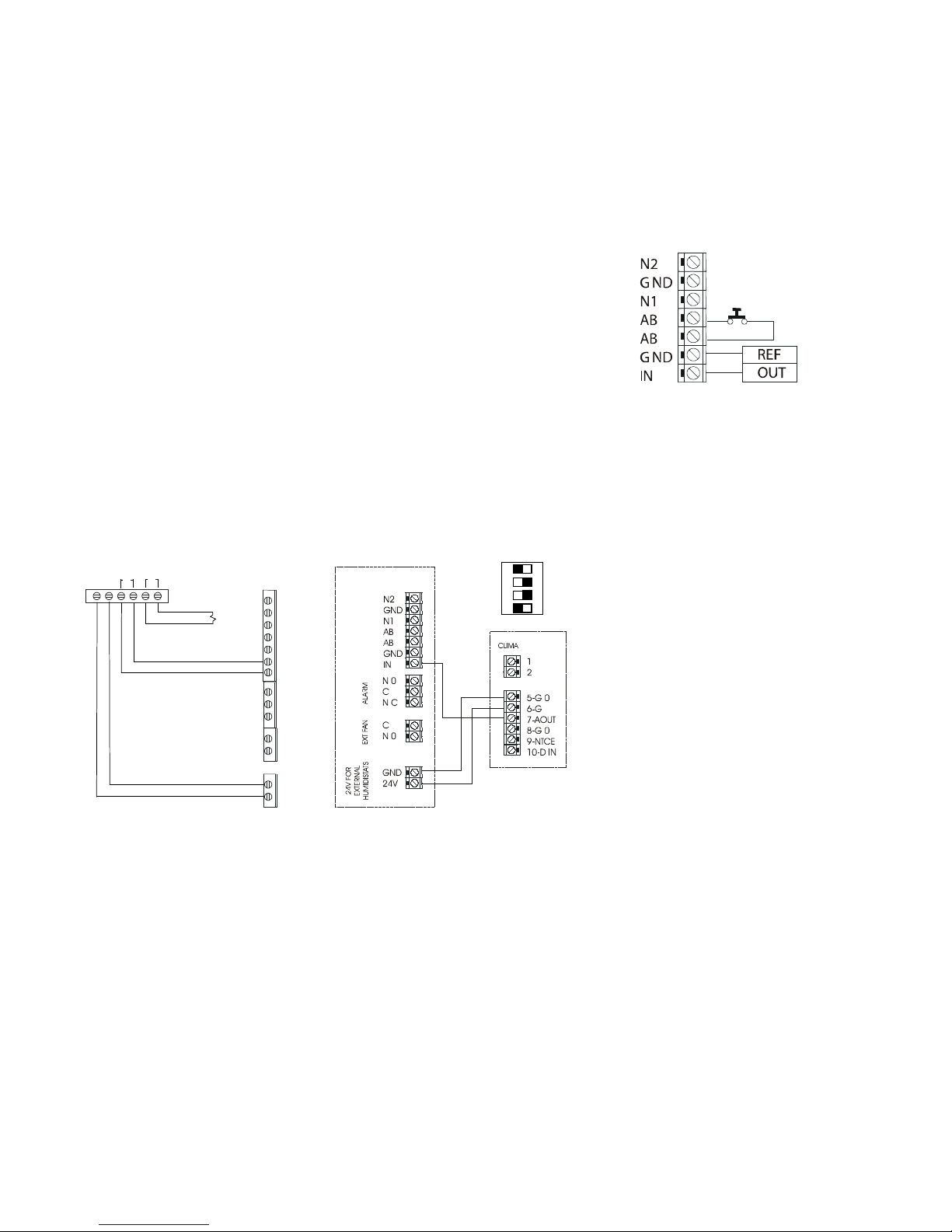
3.6.2 Modulating Operation
Connect an external 0...10 Vdc modulating input between terminals IN-GND. Connect any
Safety Switches (high-limit, air flow switch, remote on/off) in series to terminals AB-AB. If
no safety switches are used, then a jumper must be installed between AB-AB. DO NOT
PRESSURE
SWITCH
apply any voltage to AB-AB.
3.6.3 Connect the GFX50 humidistat for Modulating Operation
To select signal modulating see Fig 3.y Connect the power supply to the GFX50 G and G
EXTERNAL
REGULATOR
O terminals, using the terminal GND and 24V on the Elite Steam. Note MODULATING
OPERATION requires a change in signal type. See SEC. 5.1.1 page 19.
Connect an external signal to the
AOUT in
GFX50.
GFX50 using the terminal IN from the Elite Steam and
See the diagram below.
GFX3 HUMIDISTAT GFX50 HUMIDISTAT AIR CONDITIONER RELAY INTERLOCK
3.6.4 Safety and High Limit Switches
Remove the jumper between terminals AB-AB and connect any simple high-limits, air flow switch, 12500 pressure switch, and
remote contacts in series to terminals AB-AB; otherwise, if no such dry contacts are available, the jumper must remain in place
between terminals AB-AB. DO NOT apply any voltage to AB-AB.
Thread the control wiring through the bottom of the unit, and the strain relief (see photo at top of previous page), and then up the
side of the control module to the top right wiring terminal blocks. Connect the control wiring to the control wiring terminal blocks
found at the top right side of the control module.
3.6.5 Air Conditioner Relay Interlock
Auxiliary DPDT safety relay: Use this method in the following situations:
1. To prevent the air conditioner from running when there is a call from humidity. The DPDT relay will open the “Y” circuit and close
the “G” circuit for operation while a call for humidity is present. Demand for humidity will override call for cooling.
2. In systems using a thermostat where G and Y are a single circuit. The DPDT relay will allow blower operation to occur without
back-feeding the compressor.
Do not use this method when simultaneous humidification and cooling will be desired. Use a high limit humidistat in to avoid
condensation in ductwork.
The humidistat should be set to OFF during the air conditioning season if humidification is not desired.
For variable speed or DC systems, consult furnace manufacturer
Elite Steam +030222075 Rev. 4.0 – 2 Mar. 2015
Fig. 3.y
Fig. 3.z
.
14
Page 16

3.7 Wiring Connections:
Terminals
Functions
Electrical specifications
L1-L2 -GROUND
Power supply and Ground connections
Power supply 110 VAC 1-phase 50-60Hz 1.86kW or 230VAC 1phase 50-60Hz 4.05kW
KEY
Programming port
Connecting to Programming port or supervisor
AB-AB
Remote enabling input
Imposes an external NO contact ; Rmax=300 Ohm; Vmax=33 Vdc;
Imax=6mAdc; humidifier enabl ed = contact cl ose d
IN-GND
Control signal input
If programmed 0...10V:
Input impedance 10 kohm
Imax = 5mA Rmax = 300 Ohm
NC-C-NO
NC alarm contact
NO alarm contact
250V; 8Amp max with resistive load; 4 Amp max with inductive
load
24GND
Power for external humidistat
Power supply for external humidistat 24 Vac; 2 Watt
KEY FOR PROGRAMMING PORT:
DP = DRAIN PUMP
DT = DRAIN TEMPERINGVALVE
HL = HIGH-LEVELSENSOR
EVF = FILL VALVE
CONNECT ED
TO GROUND
POWER SUPPLY
(110VAC 1-PHASE 50-60 HZ
OR
230 VAC 1-PHASE50-60HZ)
24VACFOR
EXTERNAL
HUMIDISTATS
EXTERNALDUCT FAN
ALARM
HUMIDISTAT
AIR PRESSURE SWITCH
PROGRAMMING
PORT
IN GND AB AB N1 GND N2
NO C
NC C NO
24Vac GND
KEYBOARD
EXT FAN ALARM
KEY
HL
N
EVF
DP
N
F
INT
FAN
E1
E2
L1 L2
8
2
4
EMBEDDED
BLOWER
ON-OFF
BOTTON
6
EXTERNAL FUSED
DISCONNECTTO BE
INSTALLED(NOT
SUPPLIED) RESPECT
LOCAL CODES
HL
STEAM
BOILER UNIT
DP
DT EVF
DRY CONTACTS,
If programmed ON-OFF:
Vmax 33Vdc
Common alarm contact
load
NO-C External fan relay 250V; 8Amp max with resistive load; 4 Amp max with inductive
3.7.1 Wiring diagram of controller
EXTERNAL FAN
HOOKUP
Elite Steam +030222075 Rev. 4.0 – 2 Mar. 2015
Fig. 3.z.1
15
Page 17

2.
Maintenance
3.
Display is amperage (default)
4.
Steam is being produced
5.
Cylinder filling
6.
Foaming
7.
Water presence inside the cylinder
9.
LEDs indicate: power (yellow), operation (green) and alarms (red)
10.
Drain button for manual draining of cylinder and confirming parameter values
12.
Reset button to reset alarms and access parameters
13.
Level of output: 33%, 66%, 100%
1
2
4
5
6
9
10
12
13
14
11
3
7
8
4. START-UP
IMPORTANT WARNINGS:
1. Before starting, check that the humidifier is in perfect condition, that there are no water leaks and that the electrical parts
are dry;
2. Do not connect power if the humidifier is damaged or even partially wet!
When installation is completed, flush the supply pipe for around 10 minutes by piping water directly into the drain, without sending it
into the humidifier; this will eliminate any scale or residues that may cause foam when boiling.
4.1 Startup Checklist
Before starting the humidifier, the follow ing shou ld be chec ke d:
• Water is connected, the line has been flushed, and external valves are open.
• Drain is connected, run to an open drain, and has a trap under the unit.
• Electricity is connected in accordance with instructions, local codes and data labels in the unit.
• The power fuses are installed and intact.
• All control wiring is done and tested.
• Airflow switch is wired to open on air flow loss.
• Hi-limit humidistat is wired to open on humidity rise above set point.
• Unit wires have been checked to make sure they and all connectors are tight from shipping.
• The steam hose(s) are run correctly with no sags or kinks and sloped properly according to the manual.
• Condensate hoses are run correctly with no sags or kinks and sloped properly according to the manual.
4.2 The Elite Steam Controller
The Elite Steam controller features a comprehensive information display that shows the operation of the system at a glance:
1. Display is % of nominal capacity
8. Cylinder draining
11. ON/OFF button
14. Fan relay is activated
The Elite Steam is now ready to operate.
4.3 Starting Elite Steam
• Insure that the external power is turned on.
• Push the top part of the On/Off button so that the I part is in. The yellow Power LED will be
lit. The Elite Steam is now ready to operate.
• When there is a call for humidity, Elite Steam will close its power relays and send power to
the electrodes in the plastic steam generator. The green Operation LED will light, indicating
that operation has begun.
4.4 Starting with a new cylinder
When starting with a new cylinder, you should activate the cylinder cleaning function as follows:
1. Switch Elite Steam off.
2. Press and hold both buttons, “reset” and “drain”, and switch Elite Steam back on. When the
wrench blinks then release the two buttons.
3. Press and hold “reset” until the display shows 04.
WARNING: DO NOT confirm any value higher than 04. If 05 or higher is displayed, press “reset” until the display goes back to
the normal operating mode and restart from step
4. Press “drain” (minimum 1 second): the cleaning starts and the display shows PC.
During the cleani ng, the electrodes are power ed and water is filled in until it touches the high-level sensor or the phas e current equals 20A,
whichever occurs first. After either of the events is detected, the boiler is fully discharged with the electrodes un-powered (the drain pump and
the drain tempering valve are activated for 3 minutes). W arming the filling water helps washing out any mould releas e or dirt. General Filters,
Inc. recommends doing two cleanings when starting a new boiler. After the cleaning ends, the humidi fier starts the regular duty. When starting
the unit with a new or emp t y cylinder, it m ay tak e a s ignif icant a mount of time (ho urs) f or the uni t to bui ld u p en ough mine ral con centration to
reach rated capacity. This time can be shortened by the addition of Alka-Seltzer through the steam outlet on top of the cylinder.
Elite Steam +030222075 Rev. 4.0 – 2 Mar. 2015
16
Page 18

5. OPERATING ELITE STEAM
5.1 Displaying Information
By pressing the “reset” button for 2 seconds, the display will loop from amperage to production in % of the maximum production to
the hour counter and back to amperage:
Fig. 5.a
1. Amperage: it is the value of the current that flows through the water making it boiling off (default display)
2. Production %: it is the current production expressed as a percentage of the humidifier’s capacity
3. Hour counter, expressed in tens; for instance, when the display shows 13 the real hour value will be between 130 and 139
hours.
5.1.1 Select Signal Type
The Elite Steam is preset for the included GFX3 humidistat (signal type 0). If the included humidistat is used, this section may be
omitted. If another humidistat is used, review this section to see if changes are needed.
1. Switch Elite Steam off.
2. Press and hold both buttons “reset” and “drain” and switch Elite Steam back on. When the wrench blinks,
release the
2 buttons.
3. Press “Reset” until the display shows 02. WARNING: DO NOT confirm any value higher than 04. If 05 or higher is
displayed, press “Reset” until the display goes back to the normal operating mode and restart from step 1.
4. Press “drain” (minimum 1 second) to confirm: the display shows “P1” then the current signal type and “set”
5. Press “Reset” to change signal type between 0 and 1:
0 = On-Off humidistat such as the GeneralAire “M” or “GFX” series humidistat.
1 = external 0...10 Vdc modulating signal such as the GeneralAire
®
ADCD series humidistat
6. Press “drain” (minimum 1 second) when done to confirm the new value of P1 and exit to the normal operatin g mode.
7. Switch Elite Steam off: you can now proceed with connecting the control wiring.
5.2 Changing The Maximum Production
The maximum production can be adjusted between 20% to 100% of the nominal production in steps of 5% in order to suit the
environmental characteristics. DS25 and RS25 Maximum production is factory set at 70%.
1. Switch Elite Steam off.
2. Press both and hold both buttons “Reset” and “Drain” , and switch Elite Steam back on. When the wrench blinks;
release the 2 buttons.
3. Press “reset” until the display shows 01. WARNING: DO NOT confirm any value higher than 04. If 05 or higher is displayed,
press "Reset" until the display goes back to the normal operating mode and restart from step 1.
4. Press “drain” (minimum 1 second) the display shows “P0” then the current Maximum Production Percent and “set”.
5. Press “reset” to change the Maximum Production in steps of 5% between 20% and 100%.
6. Press and hold “drain” (minimum 1 second) when done to confirm the new Maximum Production and exit to the normal
operating mode.
5.3 Activating Manual Drain
Press and hold the “drain” button on the front of the unit until the cylinder is drained. Note: Water will continue to flow from the
tempering valve after the cylinder is empty.
5.4 Resetting the hour counter
The hour counter should be reset every time the cylinder is changed in order to reset and r estart the internal maintenance timer:
1. Switch Elite Steam off.
2. Press and hold both buttons “Reset” and “Drain” and switch Elite Steam back on. When the branch
buttons.
3. Press and hold “reset” until the display shows 03. WARNING: DO NOT confirm any value higher than 04. If 05 or higher is
displayed, press “reset” until the display goes back to the normal operating mode and restart from step 1.
4. Press “drain” (minimum 1 second) to confirm: the hour counter will be reset at once and Elite Steam will go back to the normal
operating mode.
blinks; release
Elite Steam +030222075 Rev. 4.0 – 2 Mar. 2015
17
Page 19

5.5 Using the GFX3 Humidistat
play
Led
Relay
--
Remote on-off open
Unit disabled
Off
Off EE
Internal memory error
Unit disabled
On
On E0
Control board configuration not valid
Unit disabled
On
On
Turn off, check control boar d, reprogram
E1
High current alarm
Unit disabled
On
On
Turn off, check connections, check
electrodes, no electrodes short-circuited)
E2
Low production, low supply water
Unit disabled.
On
On
Check supply water conductivity (too
E3
Press “reset/sel” key for 1 seconds to reset.
Off
Off
Change cylinder (not urgent)
timeout)
(critical performance detected)
produce the demand, otherwise turn off and then on.
reset/sel
cylinder”)
Resetting the hour counter”)
176 °F / 80 °C)
decreases below 176 °F / 80 °C.
the controller.
Suggested
Setting
Outdoor
Temperatures
15%
-20˚F -29˚C
20%
-10˚F -23˚C
25%
0˚F -18˚C
30%
+10˚F -12˚C
35%
+20˚F - 7˚C
40%
+30˚F - 1˚C
Press to select OFF, MANUAL or AUTO mode (if outd oor s ensor is connected).
OFF mode: The humidifier is turned off.
MANUAL mode: The GFX3 will work to maintain the single humidity selected. You can set
your desired humidity level by pressing
or . The humidifier will turn ON or OFF
according to your manual setting. (The humidifier will operate when the measured relative
humidity falls more than 2% below the set point.) Humidity will have to be lowered when
weather is colder or if condensation is suspected.
AUTO mode: The GFX3 will automatically raise the humidity as the outdoor temperature
increases. This provides the highest possible humidity. The GFX3 will automatically lower the humidity as temperatures drop. This
minimizes the risk of condensation on cold surfaces like windows. You can adjust the Auto Humidity Index Set Point from 0 (low) to
10 (high) by pressing or . The Humidity Index is based on the outdoor temperature and indoor humidity. The humidifier will
switch ON/OFF according to the calculated auto humidity index set point. Lower Index settings are for older homes with less
insulation and vapor barriers. Higher Index settings are for newer homes with complete vapor barriers, triple pane windows and high
R value insulation. If condensation occurs reduce Index setting by 2 points until condensation stops.
NOTE If the outdoor temperature sensor fails, flashes and the unit will default to MANUAL mode.
To toggle between indoor / outdoor temperature and indoor humidity: Press .
To change the temperature unit: Press °C / °F.
To set the temperature / humidity offset in MANUAL or AUTO mode:
1. Simultaneously press and when viewing the temperature or humidity reading.
2. Use
3. Press and simultaneously or wait 5 seconds to confirm and move onto the next setting.
or to change the setting (-3 to 3).
WARNING: Do not allow excess humidification. Excess humidity can cause condensation and enable mold and mildew growth.
5.6 Alarms
In the event of an alarm, the red alarm LED will flash, the alarm relay will close, and the alarm code will flash in the display. Multiple
alarms will flash in sequence, alternating with the main display. Pressing the sel button for 2 seconds will reset the alarms, although
still active alarms will continue to display.
Dis
Description Action Red
Alarm
Notes
conductivity or excessive
foam/limescale in the cylinder
Cylinder almost exhaus ted, already
used for 20 00 hrs
E4 Fill alarm, unable or slow fill
(current does not increase within
timeout)
E5 Drain alarm, unable to drain
(current does not decre ase wi thi n
E6 Cylinder exhausted
E7 Foam detected
E8 Cylinder lifetime expired (3000 hours) Unit disabled: Reset the hour counter (read chap.
E9 High controller temperature (above
Press “reset/sel” key for 1 seconds to reset.
Press “reset/sel” key for 1 seconds to reset, otherwise
the warning will be reset automatically every 10
minutes until the supply water is available again.
Press “reset/sel” key for 1 seconds to reset
The warning is automatically reset if Elite Steam can
Press “
The warning is automatically reset if the temperature
” key for 1 seconds to reset
cylinder (no limescale bridges between
low?), replace the cylinder.
On On Check water supply and fill valve; check
On On Check drain pump and drain connection
Off Off Change cylinder (urgent)
Off Off If it continues, do some cleaning cycles
On On Change the cylinder if necessary
Off Off Check the ambient temperature, replace
drain pump for leakage
(read chap. “
Starting with a new
Elite Steam +030222075 Rev. 4.0 – 2 Mar. 2015
18
Page 20

Problem
Causes
Solutions
The humidifier does not start
1. Remote ON/OFF contact open
1. Close ON/OFF contacts
The humidifier fills with water
1. High steam back pressure
1. Check that the steam hose is not kinked or sagging,
The humidifier wets the duct
1. The distributor is not installed correctly (too
1. Check that the steam distributor is installed correctly
ventilation in the duct
The humidifier wets the floor
1. The humidifier drain is blocked
1. Clean the drain assembly and pan
Problem
Causes
Solutions
Water in the cylinder turns
1. Minerals in the cylinder have overand are deteriorating the
1. Check for sags & kinks that could trap condensate in the
steam hoses that could cause a back pressure on the
5. Correct installation problems and replace cylinder.
Heavy arcing occurs within
1. The feed water contains large a m ounts of I ron,
1. Contact the factory for an optional drain timer to force
not damaged in shipping.
Humidifier continuously fills
ains without producing
4. Consider using a mix of demineralized water with raw
d. If feed water
contains silica or nitrates, install a 1 micron water filter.
6. TROUBLE SHOOTING
The humidifier does not turn on 1. No electrical power
operation
without producing steam
below
2. On/off switch of the humidifier in position 0
(open)
3. Control connectors improperly connected
4. Blown fuses
5. Transformer failure
2. The humidistat has not been connected
correctly
3. Humidistat failure
4. Control signal not compatible with the type set
5. Value measured by the sensor/s higher than
the corresponding set point
2. Fill valve strainer clogged
3. Mineral in the fill cup
4. Drain pump valve leaking
near the top of the duct or the condensate return
is blocked)
2.Air flow rate is too low
3.Humidifier active when the fan in the duct is off
2. The supply water or overflow circuit has leaks
3. The condensate drain pipe does not bring the
water back to the drain pan
4. The steam hose is not properly fastened to the
cylinder
5. The bushing and / or O-ring at the base of the
cylinder are missing or not properly seated.
1. Check the safety devices upstream from the humidifier
and the presence of power
2. Close the switch on the panel: position I
3. Check that connectors are properly inserted in terminal
block
4. Check the condition of fuses
5. Check that the proper voltage is connected and turned on
2. Check the external connection
3. Replace the humidistat
trapping condensate
2. Clean the fill valve strainer
3. Clean the fill cup
4. Check for voltage at the drain pump valve and/or drain
pump replacement
2. Increase air flow in duct or decrease PO maximum steam
production setting
3. Check the connection of the device (flow switch or
differential pressure switch) controlling the humidifier to the
2. Check the entire water circuit
3. Check the correct position of the condensate drain hose
in the drain pan
4. Check the fastening of the hose clamps on the steam
outlet
5. Lift out the cylinder and check to see the bushing and / or
O-ring are properly seated. See illustration page 21.
Tab. 6.a
black
hours of startup
and dr
steam
concentrated
electrodes.
Copper or other conductive contaminants.
1. Mineral has bridged between the electrodes.
2. There is back pressure from the steam hoses
or duct.
3. The flow regulator in the fill valve is broken or
out of place.
4. Water conductivity is very high.
5. Water is foaming excessively.
Elite Steam +030222075 Rev. 4.0 – 2 Mar. 2015
cylinder.
2. Check the duct static pressure.
3. Check the fill valve and inlet strainer.
4. Check the drain pump operation.
additional drains to control the minerals.
2. If you are using a softener. Discontinue use.
3. Check the electrodes in the cylinder to be sure they were
1. Clean or replace the cylinder.
2. Check the steam hoses for kinks or gullies t hat might be
trapping condensate.
3. Replace the fill valve.
water.
5. Check cylinder - replace if exhauste
Tab. 6.b
19
Page 21

20%100%
Maximum Production
Cylinder
life
Fig. 7.b.
Fig. 7.c.
Bushing
Red O-Ring
7.1 Periodic checks
• After one hour of operation: Check that there are no significant water leaks.
• Every fifteen days or no more than 300 operating hours: Check operation, that there are no significant water leaks and the
general condition of the cylinder. Check that during operation there is no arcing between the electrodes.
• Every three months or no more than 1000 operating hours: Check operation, that there are no significant water leaks and, if
necessary, replace the cylinder. Check that there are no blackened parts of the cylinder. If there are blackened parts of the
cylinder, check the condition of the electrodes, and if necessary replace the cylinder.
• Annually or no more than 2500 operating hours: Replace the cylinder.
CAUTION: ALWAYS DISCONNECT THE M AIN POWER BEFORE DOING MAINTENANCE!
CAUTION: always disconnect the main power before touching the cylinder in the event of leaks, as current may flow through the water.
7.2 Cylinder maintenance
The life of the cylinder depends on a number of factors, including: the amount and type of mineral in the water, the correct use and
sizing of the humidifier, and the output, as well as careful and regular maintenance. Another factor affecting cylinder life is
Maximum Production, the higher the production rate the shorter the cylinder life; for this reason the DS-25 and RS-25 are preset
from the factory at 70%. Further reductions in maximum production will extend cylinder life. See figure 7.a
IMPORTANT WARNINGS
The humidifier and its cylinder contain live electrical components and hot surfaces, and therefore all service
and/or maintenance operations must be performed by expert and qualified personnel, who are aware of the
necessary precautions. Before performing any operations on the cylinder, check that the humidifier is
disconnected from the power supply. Remove the cylinder from the humidifier only after having drained it
completely using the manual “drain” butt on or procedure. Check that the model and the power supply voltage
of the new cylinder correspond to the data on the rating label.
7.2.1 Replacing the cylinder
IMPORTANT WARNING: the cylinder may be hot. Allow it to cool before touching it or use protective gloves.
Fig. 7.a
To replace the cylinder:
1. Completely drain the cylinder by pressing and holding the “drain” button until the cylinder is empty;
2. Turn the humidifier off and disconnect the main power;
3. Remove the cover;
4. DS Models:
o Remove the steam hose from the cylinder;
o Flip up the cylinder holdi ng brack et and lift t he cylinder out of the unit;
o Disconnect the steam hose adapter from the cylinder and lift the cylinder out of the unit. Bushing and O-ring
may fall out with cylinder removal. If so, re-seat a NEW O-ring and existing bushing back in the base.
5. RS Models:
o Undo the 2 bolts of the embedded fan;
o Flip up the cylinder holding bracket;
6. Disconnect the distributor from the cylinder and lift the cylinder out of the unit;
7. Set bushing to side. Do NOT discard bushing. Dispose of red O-Ring.
8. Disconnect the electrical connections from the top of the cylinder;
9. Ensure NEW O-ring and bushing are properly re-seated before inserting new cylinder. See figure 7.c.
10. Install the new cylinder in the humidifier by performing the prev ious oper atio ns in rever se
CAUTION: Do not tighten the 7/8” hose clamp so tight that it crushes the cylinder outlet
WARNING: Electrical connections to the cylinder must be tight or possible fire hazard may result.
Threaded nuts on power wires must be connected with 44 in-lbs ± 10% (5 Nm ± 10%).
7.2.2 Maintenance of the other plumbing components IMPORTANT WARNINGS:
• External power must always be disconnected when performing any maintenance on the humidifier.
• When cleaning the plastic components do not use detergents or solvents;
• Scale can be removed using a solution by using vinegar or a weak solution of acetic acid and a soft brush; then rinse the
cylinder thoroughly with fresh water.
Cleaning the fill valve:
After having disconnected the cables and the hoses, remove the valve and check the condition of the inlet filter; clean if
necessary using the same cleaning solution as for the steam cylinder and a soft brush.
Cleaning the drain pump:
Remove the valve body, clean if necessary using the same cleaning solution as for the steam cylinder and a soft brush.
Cleaning the drain pan:
Clean the pan of any mineral deposits and check that the water flows freely from the pan to the drain at the drain pump.
Cleaning the supply, fill, overflow pipes: Check that these are clear and clean or replace if necessary.
IMPORTANT WARNING: after having replaced or checked the plumbing, check that components have been reconnected correctly
with the proper seals. Re-start the humidifier and perform a number of cleaning cycles (from 2 to 4, read chap. “Starting with a new
cylinder”), then check for any water leaks.
Elite Steam +030222075 Rev. 4.0 – 2 Mar. 2015
7. MAINTENANCE
AKA: Gasket
REPLACE WITH NEW
KEEP AND
RE-SEAT
20
Page 22

7.3 Replacement Parts
12
12
4
5
1
3
8
6
14
10
11
7
9
12
2
15
Item
Part No.
Description
1
See the table below
Steam generator cylinder
7801
3
7551
35-18 ON/OFF SWITCH FOR CH SERIES
7535
35-2 ROOM BLOWER ASSEMBLY 230/1 FOR CH SERIES
5
7544
35-19 BLOWER FILTER KIT FOR CH SERIES
7802
7803
25-3 FILL SOLENOID VALVE + DRAIN TEMPERING 230 V FOR DRAIN PUMP
7804
15-7 KIT FOR DRAIN PUMP 110V
7805
9
7542
35-21 90 DEGREE DRAIN ADAPTER FOR CH SERIES
10
7806
25-2 FILL TANK + PLUG FOR DRAIN PUMP
12
7553
35-25 COVER HOLDING SCREWS FOR CH SERIES
14
15
7811
25-50 WIRING KIT FOR UNIT WITH DRAIN PUMP
16
Item
Part No.
Description
1
7523
15-14 CYLINDER STD. CONDUCTIVITY 110/ 1 5.5 LBS/ HR DS15P, RS15P, DS15, RS15
1
7524
35-14 CYLINDER STD. CONDUCTIVITY 230/1 12 LBS/HR DS25, RS25, DS25LC, RS25LC
1
1
7516
20-14A CYLINDER STD. CONDUCTIVITY 230/1 7 LBS/HR DS20A, RS20A
7552
35-16 INTERNAL FILTER AND GASKET KIT FOR CYLINDER
Expanded View of Bushing
16
& O-Ring Placement
2
4
6 7536 35-20 INTERNAL STEAM DISTRIBUTOR MANIFOLD FOR CH SERIES
7
8
11
7800
7534 15-2 ROOM BLOWER ASSEMBLY 110/1 FOR CH SERIES
25-1 CONTROL MODULE 5.4 kg/h 230V WITH DRAIN PUMP
15-5 CONTROL MODULE 2.5 kg/h 110V WITHN DRAIN PUMP
15-6 FILL SOLENOID VALVE + DRAIN TEMPERING 110 V FOR DRAIN PUMP
25-7 KIT FOR DRAIN PUMP 230V
7807 25-4 ROOM TUBING KIT FOR DRAIN PUMP
7808 25-5 DUCT TUBING KIT FOR DRAIN PUMP
7809 25-6 BOTTOM TANK FOR DRAIN PUMP
7810 25-8 DRAIN TANK + PLUG FOR DRAIN PUMP
7815 25-12 STEAM CYLINDER HOSE ADAPTER
7685 BUSHING KIT FOR 15 & 25 MODEL STEAM HUMIDIFIERS (BUSHING & O-RING)
7543 35-15 CYLINDER LOW CONDUCTIVITY 230/1 12 LBS/HR DS25, RS25, DS25LC, RS25LC
Elite Steam +030222075 Rev. 4.0 – 2 Mar. 2015
21
Page 23

5.5 lbs/hr (2.5 kg/h): 110 VAC 1-phase 50-60 Hz, 1.86 kW
12 lbs/hr (5.4 kg/h): 230 VAC 1-phase 50-60 Hz, 4.05 kW
Steam pressure
3.81 in WC / 950 Pa
For duct only
24” x 14” x 8” (600 x 341 x 204 mm)
Weight empty/packaged/installed
with water
18/22/26 lbs. (8/10/12 kg)
IP20
Electrode power cables
12 AWG
Power relays
2 x 30 Amp
on board
Screw
Input water type
Potable water
no demin. or softened water
Conductivity range
125-1250 µS/cm
Special cylinders for cond. < 350
1/4” O.D. Compression
Water fill - instant flow
0.09 – 0.16 gpm
(0.35 – 0.60 l/min)
32 mm O.D. (1.25”)
unit.
Drain water temp
< 140°F
(< 60°C)
drain tempering device
Initial Max drain rate - 7 gpm (26.2 l/min) (w/ full cylinder –
one minute period starting with full cylinder)
71 cfm
(120 m³/hr)
RS485
Steam flows, VAC, kW
8. TECHNICAL SPECIFICATIONS
Notes
Dimensions (mm )
IP class
Ground connection
Water fill connection
Drain connection
Drain flow
Embedded fan flow
Serial communication
(Height x Width x Depth)
Adapter to ¾” FPS
Adjustable from horizontal to
vertical.
May be from back or bottom of
for the first 10-15 seconds of drain cycle)
Average drain rate – 3.1 gpm (11.7 l/min) (measured over a
Direct Room Discharge Only
Unit Voltages
Primary 120 / 240 Volts AC
Control Wiring 12 Volts DC
Elite Steam +030222075 Rev. 4.0 – 2 Mar. 2015
22
Page 24

9. LIMITED WARRANTY
DS and RS Residential Humidifiers, if properly registered by the return of the page 25 warranty registration to General Filters, Inc.,
are warranted to the consumer against defects in materials and workmanship for a period of two years from the date of installation,
so long as the product has been installed and operated in accordance with all appropriate manuals and wiring diagrams in a
residential structure.
Install ation in comm ercial, industrial or office building will void all warranties. Installation to a water source that does not meet unit
specification will void all warranties. Replacement of routinely replaceable parts such as steam cylinders and gaskets, are not
covered by this limited warranty or any other warranties.
Any other defective parts will be repaired without charge except for removal, reinstallation and transportation costs. To obtain repair
service under this limited warranty, the consumer must send the defective part to General Filters, Inc.
THERE ARE NO EXPRESS WARRANTIES COVERING THIS HUMIDIFIER OTHER THAN AS SET FORTH ABOVE. THE
IMPLIED WARRANTIES OF MERCHANTABILITY AND FITNESS FOR A PARTICULAR PURPOSE ARE EXPRESSLY
EXCLUDED. THE MANUFACTURER ASSUMES NO LIABILITY IN CONNECTION WITH THE INSTALL ATION OR USE OF THIS
PRODUCT, EXCEPT AS STATED IN THE LIMITED WARRANTY. THE MANUFACTURER WILL IN NO EVENT BE LIABLE FOR
INCIDENTAL OR CONSEQUENTIAL DAMAGES. This limited warranty gives you specific legal rights, and you may also have other
rights which vary from state to state. Some states do not allow either limitations on implied warranties, or exclusions from incidental
or consequential damages, so the above exclusion and limitation may not apply to you.
Any questions pertaining to this limited warranty should be addressed to General Filters, Inc. General Filters, Inc. has elected not to
make available the informal dispute settlement mechanism which is specified in the Magnuson-M oss Warranty Act.
Register your warranty online USA: www.generalfilters.com / Support Center
Register your warranty online Canada: www.cgfproducts.com / Warranty Regist rat ion
GENERAL FILTERS, INC CANADIAN GENERAL FILTERS, INC
43800 GRAND RIVER AVENUE 400 MIDWEST ROAD
NOVI, MI. 48375 TORONTO, ON M1P3A9
www.generalfilters.com www.cgfproducts.com
Elite Steam +030222075 Rev. 4.0 – 2 Mar. 2015
23
Page 25

FERMER LA BRIDE DU BALLON
RETIRER AVANT INSTALLATION
RETIRER AVANT INSTALLATION
RETIRER AVANT INSTALLATION
RETIRER AVANT INSTALLATION
RETIRER AVANT INSTALLATION
Mise en garde
Si présents, retirer les éléments suivants:
Elite Steam +030222075 Rev. 4.0 – 2 Mar. 2015
24
Page 26

MISES EN GARDE IMPORTANTES:
AVANT D’INSTALLER OU DE MANIPULER L'HUMIDIFICATEUR, LIRE ET SUIVRE ATTENTIVEMENT LES INSTRUCTIONS ET
LES INDICATIONS DE SÉCURITÉ DÉCRITES DANS CE MANUEL ET SUR LES ÉTIQUETTES APPLIQUÉES SUR L’Elite Steam.
TOUJOURS COUPER L’ALIMENTATION PRINCIPALE AV ANT D’OUVRIR OU DE RÉPARER L'HUMIDIFICATEUR!
Elite Steam produit de la vapeur non-pressurisée à l’aide d’électrodes immergées dans de l’eau contenue dans un ballon plastique
générateur de vapeur. Le courant électrique circule à travers l’eau entre les électrodes, réchauffant ainsi l’eau pour créer de la
vapeur, qui est ensuite utilisée pour humidifier l’air.
La qualité de l’eau utilisée est importante pour le fonctionnement de l’unité. Elite Steam doit être alimenté avec de l’eau non-traitée,
tant qu’elle est potable ni adoucie ni déminéralisée. L’eau transformée en vapeur est automatiquement remplacée à travers une
vanne électrique de remplissage. L'unité évacuera également de l’eau périodiquement, en fonction de la qualité de l’eau, pour
éliminer l’accumulation de minéraux dans le générateur de vapeur. En cas de présence importante de minéraux dans l’eau, un filtre
à charbon actif est doté d’un filtre à particules infér ieur s à 5 microns .
Cet humidificateur a été exclusivement conçu pour humidifier directement des pièces ou des conduits, par l’utilisation d’un système
de distribution. Les opérations d’installation, d’utilisation et de maintenance doivent être effectuées dans le respect des instructions
contenues dans ce manuel et sur les étiquettes appliquées à l’intérieur ou à l’extérieur.
ATTENTION: AVANT de commencer l’installation :
• Contrôler l'absence de dommages dus au transport sur les cartons d'emballages. Remplir la lettre de transport en conséquence.
• Ouvrir les cartons et vérifier l’absence de tout dommage caché. Remplir la lettre de transport en conséquence.
• Contrôler le bon de livraison pour vérifier que tous les articles ont bien été reçus. Avertir GENERAL FILTERS, INC. en cas
d’absence de pièces ou de pièces endommagées. Vous devez aviser General Filters, Inc. dans les 5 jours ouvrables
en cas de pièces manquantes.
ATTENTION : RISQUE DE CHOC ÉLECTRIQUE! L’humidificateur contient des éléments sous tension!
ATTENTION : RISQUE DE BRÛLURES! L’humidificateur contient des élém en ts chau d s (100°C / 212°F )
MISE EN GARDE: Installer l’humidificateur hors de la portée des enfants.
L’humidificateur doit être installé en accord avec les normes nationales et locales.
Toute opération d’entretien et/ou de maintenance doit être effectuée par un personnel qualifié ayant conscience des
précautions nécessaires et étant capable d’effectuer ces opérations correctement.
Débrancher l’humidificateur de l’alimentation électrique avant d’accéder aux parties internes.
Les conditions environnementales et la tension de l’alimentation électrique doivent respectées les valeurs spécifiées sur
l'étiquette des données de l’humidificateur.
Toute autre utilisation ou modification effectuée sur l’humidificateur non autorisée par le fabricant est considérée comme
impropre, le fabricant ne pourra être tenu pour responsable des conséquences de cette utilisation non autorisée.
Veuillez noter que l’humidificateur contient des dispositifs électriques et des surfaces chaudes.
MISE EN GARDE: Votre humidificateur a besoin d’eau pour fonctionner. Ne PAS le monter au-dessus de matériaux ou de
machines pouvant être endommagés suite à des fuites. General Filters, Inc. ne pourra être tenu pour responsable en cas
de dommages collatéraux ou non causés par une fuite.
We wish to save you time and money!
We can assure you that the thorough
reading of this manual will guarantee
correct installat ion and saf e use of the
product described.
Élimination des pièces de l’humidificateur: l’humidificateur est constitué de pièces métalliques et plastiques. Toutes les
pièces doivent être éliminées selon les normes locales d‘él imin at ion des d éch ets.
Elite Steam +030222075 Rev. 4.0 – 2 Mar. 2015
25
Page 27

CONTENU
1. MODE DE FONCTIONNEMENT DE L’ELITE STEAM 1
1.1 F
1.2 D
1.3 C
ONCTIONNEMENT DE BASE 1
UREE DE VIE DU BALLON 2
ALCUL DE LA CHARGE D’HUMIDITE 2
2. MODÈLES 3
3. INSTALLATION 4
3.1 M
3.2 M
3.3 P
3.4 D
3.5 C
3.6 C
3.7 B
ISE EN PLACE 4
ONTAGE 4
LOMBERIE 6
ISTRIBUTION DE LA VAPEUR 7
ABLES D’ALIMENTATION 10
ABLES DE COMMANDE 10
RANCHEMENTS DES CABLES: 12
4. DÉMARRAGE 13
4.1 L
4.2 L
4.3 D
4.4 D
ISTE DE CONTROLE AVANT DEMARRAGE 13
E CONTROLEUR ELITE STEAM 13
EMARRAGE DE L’ELITE STEAM 13
EMARRAGE AVEC UN NOUVEAU BALLON 13
5. FONCTIONNEMENT DE L’ELITE STEAM 14
5.1 A
5.2 M
5.3 A
5.4 R
5.5 U
5.6 A
FFICHAGE DES INFORMATIONS 14
ODIFICATION DE LA PRODUCTION MAXIMUM 14
CTIVATION DE LA VIDANGE MANUELLE 14
EMISE A ZERO DU COMPTEUR HORAIRE 14
TILISATION DE L’HYGROSTAT GFX3 15
LARMES 15
6. RÉSOLUTION DES PROBLÈMES 16
7. MAINTENANCE 17
7.1 C
7.2 M
7.3 P
ONTROLES PERIODIQUES 17
AINTENANCE DU BALLON 17
IECES DETACHEES 18
8. SPÉCIFICATIONS TECHNIQUES 19
9. GARANTIE LIMITÉE 20
Elite Steam +030222075 Rev. 4.0 – 2 Mar. 2015
26
Page 28

1. MODE DE FONCTIONNEMENT DE L’ELI TE S TEAM
N°
Description
A
Ballon générateur de vapeur
B
Souffleur/collecteur (en option)
C
Interface utilisateur/écr an
D
Bouton d’allumage/extincti on, de séle ctio n.
de température
F
Pompe d’évacuation
Tab. 1.a
A
F
B
C
D
E
HL
DP
DT
EVF
8
9
3
13
6
10
2
4
1
11
7
12
5
Fig. 1.a
1.1 Fonctionnement de Base
Elite Steam est un humidificateur à électrode. Il produit de la vapeur pour
l’humidification en faisant circuler du courant électrique à travers de l’eau entre
des électrodes en métal dans le ballon générateur de vapeur en plastique. Il
n’y a aucun élément de chauffage. La sortie de vapeur est directement
proportionnelle à la conductivité de l’eau et à la quantité d'électrodes
immergées dans l'eau.
Lors d’une demande d’humidité, le contrôleu r d’Elite Steam ouvrira la vanne de
remplissage (1) et permettra à l’ eau d’entrer dans le ballo n. Un limiteur de débit
(4) empêche l’unité de se remplir trop rapidement ou avec trop de pression.
L’eau coule dans le tuyau de remplissage (2) et dans la c oupelle de rempli ssage
(3). L’eau passe ensui te le barrage dans la coupelle de remplissage (3), ce qui
crée un premier intervalle d’ai r qui empêche le reto ur d’eau conta minée dans les
lignes d’alimentation, et dans le tube de re mplis sage (6 ) et dans le f ond du bal lon
à vapeur (5). Tout retour ou débordement d’eau es t transporté à tra vers le tuyau
d’évacuation (13) jusqu’à l’évacuation.
Quand l’eau remplira le ballon, elle atteindra les él ectrodes (7) et le courant co mmencera alors à circuler. A mesu re que l’eau
remplira le ballon, le courant d’augmentera. Tout ceci contrôlé par un transformateu r d’intensité connecté à l’un des câbles
d’alimentation et placé sur le contrôleur élect ronique. Une fois le courant souhaité atteint, la van ne de remplis sage se fermera
(1) et l’eau commencera alors à se réchauf f er et à produire de la vape ur. Si l’ eau attei nt l es c apteurs de ballon pl ei n (9) ou s i l e
courant augmente trop rapidement, la pompe d’évacuation (11) s’activera pour évacuer de l’eau et réduire la circulation de
courant jusqu’à un niveau acceptable. Veuillez noter qu’à, chaque fois que la pompe d’évacuation est activée, la soupape
d’équilibrage de température (10) s’ouvrira pour tempérer l’eau chaude jusqu’à 140 °F / 60°C conformément aux normes locales
et nationales.
En fonction de la conductivité de l’eau, l’unité actionnera périodiquement la pompe d’évacuation (11) et évacue ra un peu
d’eau pour réduire la concentration en minéraux. Toutes les 120 heures, l’unité se vidangera automatiquement pour éliminer
les sédiments minéraux au fond du ballon. Une pass oire (12) présente dans le ballon aide à prévenir l'encombrement de la
pompe d’évacuation par des dépôts de minéraux.
Si Elite Steam reste allumé mais en défaut, c’est-à-dire sans production de vapeur, le ballon devra être vide pendant plus de
72 heures (3 jours) pour ne pas qu’il y ait d'eau stagnante à l'intérieur.
Sans eau dans le ballon, il n'y a pas de circulation de courant et donc pas de production de vapeur. Les électrodes ne se
consument pas, mais elles peuvent éventuellement être totalement recouvertes de minéraux, auquel cas le ballon devra être
remplacé. Le nettoyage du ballon peut entraîner des dommages aux électrodes, et donc annuler leur garantie. Voir la section
7.2.2 maintenance à la page 21.
Elite Steam +030222075 Rev. 4.0 – 2 Mar. 2015
Fig. 1.b
1
E
Soupape de remplissage et d’équilibrage
Page 29

Tableau 1.2 Livres d’Humidité / Heure / Pieds Carré *
Temp Int. Air
°F
35%
RH Int.%
40%
45%
50%
68
0.00015
0.00018
0.00021
0.00024
70
0.00017
0.00020
0.00023
0.00026
72
0.00019
0.00022
0.00025
0.00028
100%
20%
Durée
Fig. 1.c
1.2 Durée de Vie du Ballon
1.2.1 Éléments de Base du Ballon à Vapeur
Le Ballon à Vapeur est le moteur de l’humidific ateur. Qu and l'humidificateur fonctionne l’eau s’évapore et les minéraux s ont
filtrés. La plupart de ces minéraux sont éliminés par la vidange du ballon. Certains se déposent sur les parois du ballon et sur
les électrodes du ballon. Quand une section basse des électrodes développe une couche épaisse, le niveau d’eau monte
pour exposer une surface propre de l’ électrode. Les minéraux recouvrent éventuellement toute la longueur des électrodes
d'une couche épaisse et un faible courant électrique peut pass er entre elles ce qui entraîne une fai ble production de vapeur.
L’humidificateur peut sentir la faible intensité et affichera le code d’erreur E6 Ballon Épuisé. Il existe plusieurs facteurs qui
influencent la durée de vie du ballon.
1.2.2 L’Eau
Les caractéristiques de l’eau influencent la durée de vie du ballon et peuvent varier grandement d’un endroit à un autre. La
teneur totale en minéraux de l’eau est importante. Les minéraux présents dans l'eau ont autant d'importance. Les c onditions
de l'eau produisent souvent des dépôts calcaires qui recouvrent éventuellement le fond du ballon jusqu’à ce qu’il ne
fonctionne plus. De l’eau contenant beaucoup de silice peut créer une fine couche hautement isolante sur les électrodes et
entraînant une durée de vie plus brève du ballon. Seule de l’eau froide doit être utilisée. Une conductivité de l’eau non
adaptée au ballon écourtera la durée de vie du ballon.
1.2.3 Filtration de l’Eau
Une filtration supplémentaire de l’eau entrante n'est pas nécessaire. S’il est toutefois avéré que la teneur en minéraux réduit
excessivement la durée de vie du ballon ou que la du rée de vie du ballon est insuffisante, l’eau peut être ultér ieurement
filtrée. Dans la plupart des cas, l’ajout d’un filtre à eau à deux éléments peut améliorer la durée de vie du ballon. Le filtre doit
contenir un élément au charbon actif et un filtre à particule.
élément prévu pour 5 microns ou moins. Le micron est une unité de mesure. Le système de filtration doit avoir un débit d'au
moins 2 gal/min. Le charbon actif absorbera la plupart des minéraux alors que le filtre à particule bloquera tout matériau
granuleux ou sédiment. Il est important de se rappeler que l’augmentation de la durée de vie du ballon sera accompagnée du
besoin de remplacer les éléments du filtre avec chaque changement de ballon.
1.2.4 Charge d’Humidité et Durée de vie du Ballon
La charge d’humidité requise influence la durée de vie du ballon. Des installations normales où la capacité d’humidité est
adaptée ne nécessitent que des périodes intermittentes où la capacité de l’humidificateur doit être totale. Ceci permet au
niveau d’eau du ballon d’augmenter uniquement si les segments des électrodes deviennent isolés. Ceci tend à maximiser la
durée de vie du ballon.
Les installations extraordin aires nécessit ant un fonctionnem ent constant à une capacit é maximum réduit la durée de vie
du ballon. Le niveau d’eau dans le ballon est en moyenne plus élevé, et les électrodes deviennent totalement isolées plus
rapidement. Dans de telles applications, la durée de vie du ballon pourrait être inférieure aux 1000 heures de fonctionnement.
L’importance de fournir une capacité d’humidification adéquate ne devrait pas être sous-estimée.
1.2.5 Production Maximum
Un autre facteur affectant la durée de vie du ballon est la configuration de la production
maximum. Un taux de production plus élevé entraînera une durée de vie plus brève pour le
ballon. Pour cette raison, les unités DS-25 et RS-25 sont préréglées en usine à 70%. Des
réductions supplémentaires de Production Maximum prolongeront la durée de vie du ballon.
Voir Figure 1.c.
1.2.6 Structures en Cours de Construction
Dans les projets de construction haut de gamme, l’humidification est souvent nécessaire pendant que la structure est en
cours de finition. L’humidification est nécessaire pour protéger et stabiliser les planchers, les moulures et décorations en
bois. C’est pourquoi la charge d’humidité dans une structure non terminée doit être de cinq à huit fois plus importante qu'une
fois terminée. Les humidificateurs Elite Steam devraient fonctionnés pendant que la construction est en cours mais une
réduction de la durée de vie du ballon doit être attendue et prévue dans le budget. La bonne pratique veut que les ballons
à vapeur soient également remplacés une fois le projet terminé.
1.3 Calcul de la Charge d’Humidité
Étapes pour Déterminer la Charge d’Humidité
*Basé sur 5 renouvellements d’air par heure.
Superficie Totale
x Hauteur Moyenne Sous Plafond
X Facteur Selon Tableau 1.2
x 1.05 pour chaque Cheminée
Charge d’Humidité en lb/heure
X 2.88 converti en gallons/par jour
Charge d’Humidité en Gallons par Jour
deVie du
Ballon
* Basée sur .5 charges d’air par heure.
Elite Steam +030222075 Rev. 4.0 – 2 Mar. 2015
2
Page 30

NUMÉRO DE PIECE
DESCRIPTION
PIÈCES INCLUSES
RS 15P
Humidification d’ambiance, 15 gallons
Humidificateur Complet, hygrostat GFX3, code vanne,
en eau
RS 25
Humidification d’ambiance, 35 gallons
Humidificateur Complet, hygrostat GFX3, code vanne,
en eau
DS 15P
Injection de vapeur par conduit 15 gallons
Humidificateur seul, kit de montage requis
Humidificateur seul, kit de montage requis
DS 25
Injection de vapeur par conduit 35 gallons
Humidificateur seul, kit de montage requis
Humidificateur seul, kit de montage requis
DMNKIT
Kit de montage pour conduits
Tuyau à vapeur de 8 pieds, embouts, hygrostat GFX3, code
tuyauterie d’alimentation en eau, interrupteur à pression d’air.
120v et grille.
RMB 3 5
Kit de montage ventilation
Tuyau à vapeur de 12 pieds, hygrostat GFX3, code vanne,
240v et grille.
EDMK4
Kit de montage Conduit Économique
Tuyau à vapeur de 4 pieds, tuyau de condensat de 5 pieds,
(Hygrostat non inclus)
2. MODÈLES
Deux modèles de base sont disponibles en deux voltages différents. Les modèles pour conduits nécessitent la sélection
d’un kit additionnel.
Injection de Vapeur par Conduit Humidification d’Ambiance
Fig. 2.a Fig. 2.b
LISTE DES MODÈLES
Fig. 2.b
Fig. 2.b
Fig. 2.a
Fig. 2.a
(non représenté)
RMB 1 5
(non représenté)
(non représenté)
par jour (5.5 Lb par heure) 115-120v
par jour (12 Lb par heure) 220-240v
par jour (5.5 Lb/heure) 115-120v,
par jour (12 Lb par heure) 220-240v
Kit de montage ventilation
Kit pour DS 15
kit pour DS 25
raccord de remplissage en eau, tuyauterie pour alimentation
raccord de remplissage en eau, tuyauterie pour alimentation
vanne, raccord de remplissage en eau, tuyau de condensat,
Tuyau à vapeur de 12 pieds, hygrostat GFX3, code vanne,
tuyau de condensat, raccord de remplissage en eau, tuyau
d’alimentation en eau, et boitier mural avec souffleur de
tuyau de condensat, raccord de remplissage en eau, tuyau
d’alimentation en eau, et boitier mural avec souffleur de
(non représenté)
Elite Steam +030222075 Rev. 4.0 – 2 Mar. 2015
raccord de remplissage, interrupteur à pression d’air
3
Page 31

Millimètres
Pouces
A
341 mm
13.5“
B
204 mm
8.1“ C 600 mm
23.7“
Kilogrammes
Livres
Poids à vide
8kg
18 lb
Poids emballé
10kg
22 lb
Poids installé avec eau
12kg
26 lb
Dimensions Unité: Unités Conduit et
Injection de vapeur par
Fig. 3.a
Millimètres
Pouce
A
(150 mm)
6”
B
(150 mm)
6”
C
(150mm)
6”
D
(150 mm)
6”
E
(600 mm)
24” F max. 0.2°
Tab. 3.a
Fig. 3.c
C
D
Fig. 3.b
Millimètres
Pouce
A
150 mm
6”
B
1800 mm
72”
C
1800mm
72”
D
600 mm
24”
Humidification
3. INSTALLATION
3.1 Mise en place
L’Elite Steam a été conçu pour un montage au mur et, étant un humidificateur
atmosphérique à vapeur, il devrait être placé près de l’endroit où la vapeur sera
utilisée, pour réduire la longueur du tuyau à vapeur (et la quantité de condensat). La
zone autour de l’unité doit être dégagée pour la maintenance et la sécurité.
3.2 Montage
3.2.1 Retrait du capot frontal
Le capot frontal est fermé par quatre vis situées aux quatre coins de l’unité. Utiliser un
tournevis Phillips pour retirer les quatre vis du capot. Puis tirer simplement le capot frontal
de la partie arrière de l’unité. Le retourner dans le sens inverse.
Faire attention à ne pas serrer excessivement les vis.
Fig. 3.d
Fig. 3.e
Elite Steam +030222075 Rev. 4.0 – 2 Mar. 2015
4
Tab. 3.b
Tab. 3.c
Page 32

3.2.2 Fixation au mur
Percer le mur en suivant le modèle de perçage fourni ; fixer fermement Elite Steam au mur à l’aide des vis et des attaches
fournies.
Elite Steam +030222075 Rev. 4.0 – 2 Mar. 2015
Fig. 3.f
5
Page 33

3.3 Plomberie
Ions hydrogène (pH)
7 8.5 Ions hydrogène (pH)
7 8.5
Conductivité spécifique
(R,20°C)
μS/cm
300
Conductivité spécifique
(R,20°C)
μS/cm
125
500
Éléments solides totaux
dissous (cR)
mg/l
(*)
(*) Éléments solides totaux dissous
(cR)
mg/l
(*)
(*)
Résidu sec à 180°C
mg/l
(*)
(*) Résidu sec à 180°C
mg/l
(*)
(*)
Dureté totale
mg/l CaC³O
150
400 Dureté totale
mg/l CaC³O
0
200
Dureté temporaire
mg/l CaC³O
=
200 Dureté temporaire
mg/l CaC³O
=
150
Fer + Manganèse
mg/l F e + Mn
=
0.2 Fer + Manganèse
mg/l F e + Mn
=
0.2
Chlorures
mg/Si2O
=
20 Chlorures
mg/Si2O
=
20
Résidu de chlore
mg/l Cl-
=
0.2 Résidu de chlore
mg/l Cl-
=
0.2
Modèles ELITE STEAM
Conductivité μS/cm
Ballon à Vapeur
DS25, RS25, DS25LC, RS25LC, DS35, RS35
300-1250
35-14
DS25, RS25, DS25LC, RS25LC, DS35, RS35
125-500
35-15
DS15P, RS15P, DS15, RS15
125-1250
15-14
DS20A, RS20A
300-1250
20-14A
Fig. 3.h
Tuyau d’extension
Vanne et filtre de
remplissage
3.3.1 Caractéristiques de l’Eau
L’humidificateur doit être alimenté avec de l’eau ayant les caractéristiques suivantes:
pression comprise entre 20psi et 110psi et 0.1 et 0.8 MPa, (1 et 8 bars);
température comprise entre 33°F et 104°F ou 1°C et 40°C;
débit minimum de 0.45 L/min ou 0.12gal./min;
dureté inférieure à 40 °fH (égal à 400 ppm³ comme CaCO3), conductivité: de 125 à 1250 μS/cm;
absence de composants organiques.
les caractéristiques de l’eau d’alimentation doivent respectées les limites suivantes :
VALEURS LIMITES POUR LA TENEUR EN SEL DE L’EAU VALEURS LIMITES POUR L’EAU NORMAL
Unités
Min Max
Unités
Min
Max
Chlorures
Sulfate de Calcium
ppm Cl
mg/l CaS4O
(*) Valeurs dépendantes de la conductivité spécifique: en général: cR~=0.65*σR, 20°C; R180~=0.9*σR, 20°C
Notes: Il n’existe aucune relation démontrée entre dureté et conductivité de l’eau.
La Conductivité de L’Eau doit être associée aux spécifications du ballon à vapeur. Vérifier ou connaître la conductivité
de l’eau du site proposé avant l'installation. Remplacer le ballon à vapeur avant le démarrage si nécessaire. Consulter le
tableau 3.f.
DS20A, RS20A
Les types d’eau suivants ne sont pas acceptables:
1. Eau adoucie car elle pourrait entraîner la formation de mousse, la corrosion des
électrodes et la réduction de la durée de vie du ballon.
2. Eau contenant des désinfectants ou des produits anticorrosion, car ils sont
potentiellement irritants.
3. Eau industrielle, eau pour chaudière ou eau pour circuits de refroidissement.
4. Toute eau potentiellement contaminée par des produits chimiques ou bactériologiques.
5. Eau réchauffée.
3.3.2 Raccordement au Réseau d’eau
Nous recommandons le raccordement entre la vanne de remplissage et la ligne
d’alimentation en eau à l’aide d’un tuyau souple capable d’absorber les coups de
bélier de façon à éviter tout dommage à la vanne de remplissage. La ligne d’eau doit
passée par l'arrière ou par le bas de l'unité. Avec les tuyaux en PVC, un support doit
être utilisé pour éviter la chute des tuyaux et les fuites. Le raccord est placé ensuite à
l'entrée de la vanne de remplissage située en bas de l'humidificateur à l'aide d’un
raccord coudé 3/4". Notez qu’un filtre est présent dans la vanne de remplissage
au-dessous de l'unité, qui nécessitera un nettoyage périodique, donc s’assurer
que la zone est libre pour pouvoir y accéder.
Elite Steam +030222075 Rev. 4.0 – 2 Mar. 2015
= 30 Chlorures
= 100 Sulfate de Calcium
ppm Cl
mg/l CaS4O = 60
= 20
Tab.3.d Tab.3.e
125-500 35-14
Tab.3.f
Sortie de l’eau d’évacuation
Fig. 3.g
6
Évacuation d’eau
Page 34

3.3.3 Évacuation de l’Eau
Airflow 1000 cfm min.
Airflow
Min 8”
Height >8”
=
=
Airflow
1000 cfm min.
1/3 Height
Airflow
1000 cfm min.
=
=
8” min
24” min
Upstream
36”min
Downstream
Millimètres
Pouces
A
31.5 mm
1.24”
C
56 mm
2.20”
D
57.5 mm
2.26”
F
8 mm
0.31”
22 mm
0.86”
H
I
12 or 22 mm
0.47 or 0.87”
Fig. 3.j
Prévoir une
Frein à air
Figure 3.h.2.
L’Elite Steam requiert également un raccordement à une évacuation. La ligne d’évacuation
doit sortir de l’arrière ou du dessous de l’unité par l’intermédiaire du raccord coudé fourni. La
ligne d’évacuation peut être de 1-1/4” en PVC, CPVC ou polypropylène. La ligne d’évacuation
n’est pas collée ni accrochée à l’humidificateur donc elle doit se soutenir seule. Un collier
devrait être utilisé. L’Elite Steam inclut une soupape de remplissage et d’équilibrage de
température qui s’active dès que la pompe d’évacuation fonctionne et évacue de l’eau froide
dans la ligne d’évacuation pour assurer que la température de l'eau d'évacuation ne dépasse
par les 60°C ou 140°F.
Les caractéristiques de l'eau d'évacuation:
• Débit d’Évacuation – Voir Spécifications Techniques (Section 8 / p.24)
inclinaison de 5°
du drain à la
sortie de
l'appareil
min. 5°
• Raccord 32mm ou 1 1/4"
• Température 60°C ou 140°F
NOTES: La ligne d’évacuation doit être coincée sous l’unité pour éviter que la vapeur flash se
comprimé
4
5
condense dans le boitier de l’unité.
3.3.4 Raccords d’Évacuation
Lors de l’utilisation d’une sortie d’évacuation arrière à travers du placoplâtre, nous vous suggérons d'utiliser un tuyau
d’extension de type SJ (voir Fig. 3.f). Lors de l’utilisation d’une sortie d’évacuation inférieure, fixer le raccord à 90° inclus à la
sortie d’évacuation. La sortie d’évacuation pourrait être tournée. Fixer ensuite une douille de 1 1/4" pour raccorder le tuyau
d’évacuation.
MISE EN GARDE IMPORTANTE: Le tuyau d'évacuation doit être libre sans contre-pression. Nous vous recommandons
d’utiliser un système externe anti-inondation pour protéger contre les pannes des circuits hydrauliques externes.
3.3.5 Pompe à condensats
Lors de l'emploi d'une pompe à condensats, assurez-vous que la pompe sélectionnée peut traiter un débit de 7,0 gallons/min
pendant 10 à 15 secondes.
3.4 Distribution de la Vapeur
3.4.1 Injection de vapeur en conduit ( Kit additionnel requis)
La pression statique maximale dans le conduit est de 2 in WC.
Les modèles à injection en conduit Elite Steam inclut une b use pla stiq ue d’in je ctio n pour conduit. Voir Fig. 3.i
B 50 mm 1.96”
E 100 mm 3.93”
∅
G
∅
∅ 30 mm ∅ 1.18”
∅
∅
Fig. 3.i
IMPORTANT : N'INSTALLEZ PAS le système dans un conduit ayant une isolation par l'intérieur.
Elite Steam +030222075 Rev. 4.0 – 2 Mar. 2015
7
Page 35

3.4.2 Distribution en Conduit (Kit additionnel requis)
25-12 RACCORD DE TUYAU DU BALLON À VAPEUR
Si une buse de distribution de la vapeur doit être utilisée, sélectionner un endroit accessible du conduit, laissant un conduit droit
(pas de coude ni d'obstacle) d'au moins 36" après l'endroit où la buse est installée et les espacements peuvent être maintenus
conformément aux schémas suivants. Voir Fig.3.j pour monter la buse vapeur, couper ou percer un trou de 2-1/2” dans le conduit.
Appliquer du mastic sur la plaque de montage de la buse. Fixer la buse au conduit à l’aide de 4 vis à tôle #10 (fournies). La buse
doit être horizontale ou verticale avec la sortie du condensat en bas.
ATTENTION: Laisser 1 M ( 3 pieds ) de conduit droit en aval des tuyaux et buses de distribution pour l’absorption de la vapeur.
Toujours laisser 0.6M (2 pieds) de conduit droit en amont des tuyaux de distribution pour l’évaporation de la vapeur. Une circulation
d’air turbulente pourrait nécessiter des longueurs supplémentaires.
Tuyau de distribution en acier inoxydable en option :
Fig. 3.j
Pour installer les tuyaux de distribution:
1. Faire un trou rond du côté du conduit pour aligner le tuyau à vapeur et le retour de condensat.
2. Appliquer un joint silicone sur la plaque de montage et insérer le tuyau dans le trou et fixer à l’aide
de vis à tôle. Voir Fig. 3.k
3. Connecter les buses vapeur et le condensat à l’aide des colliers fournis.
(Notes: les équerres de soutien ne sont fournies que pour des distributeurs de 36" ou plus.)
3.4.3 Raccordement Retour de Condensat
Le tuyau de retour du condensat depuis la buse, etc . doit être coincé. Enrouler le tuyau dans une
boucle vertical et le fixer en-dessous de la buse, etc. Cette fixation empêche que la vapeur ne soit
relâchée dans le caisson. Le bout du tuyau peut passer à travers le trou en haut de l’humidificateur
et être inséré dans le trou situé en haut de la coupe de remplissage.Le trou peut être élargi pour
s’adapter. Voir Fig.3.l.
Fig. 3.l
3.4.4 Tuyaux à Vapeur
MISE EN GARDE IMPORTANTE: QUATRE-VINGT DIX POURCENT (90%) DES PROBLÈMES DE FONCTIONNEMENT
PROVIENNENT D’UNE MAUVAISE TUYAUTERIE À VAPE UR DE L’UNITÉ D’HUMIDIFICATION AUX TUYAUX DE
DISTRIBUTION EN CONDUIT.
Pour éviter ces problèmes, rappelez-vous d’une chose simple lors de l’utilisat ion du tuyau à vapeur : la vapeur circule naturellement
en montant, et le condensat naturellement en descendant. Utiliser un tuyau ou une tuyauterie à vapeur pour éviter que des pliures,
des angles ou des zones basses ne rassemble ou ne restreigne le flux de vapeur vers le tuyau de distribution, ou le flux de
condensat vers l’humidificateu r. Installer un support pour éviter les courbes du tuyau.
Les schémas suivants indiquent quelques lig nes dire ctri ce s. En cas de situation incertaine, contacter l’usine pour des instructions.
Elite Steam +030222075 Rev. 4.0 – 2 Mar. 2015
8
Page 36

20%
YES
NO
≥20%
A
C
B
D
Millimeters
Inch
A
150 mm
6” B 1800 mm
72”
C
600 mm
24” D 2100 mm
84”
Fig. 3.n
IF NO TRAP
1,5 m (5 FT max.)
5%
WITH TRAP
1,5 m (5 FT max.)
IF NO SLOPE
20%
0,9 m (3 FT max.)
3 m (10 FT max.)
1,5 m (5 FT max.)
20% 20%
SUPPORTED STEAM HOSE
AND/ORCOPPER PIPE
NOTES:
• SLOPEPIPING UPIN DIRECTION OF STEAM FLOWAT 20% OR GREATER, WHICH MEANS 65,5mm x305mm (2 1/2” PER FOOT);
• SLOPEPIPING DOWN IN THE DIRECTION OF STEAM FLOWAT 5% OR GREATER, WHICH MEANS 20mm x 305mm (3/4” PER FOOT);
• MAX. LENGTH OF RUBBER STEAM HOSE IS 3 m (10 FT).
• HEIGHT OF P-TRAPSMUSTBE GREATER THAN THE D UCT STATIC PRESSURE.
NO SLOPE
KINKED
GENTLE BEND
OBSTRUCTION
SAG
5%
NO TRAP
DRAINS
P - TRAP
NOTE: HEIGHT OF TRAPSMUSTBE GREATER
THAN THE DUCT STATIC PRESSURE
NO SLOPE
UNDRAINED
ELBOW
TYPICAL INSTALLATION
WHEN UNIT IS ABOVE
THE DISTRIBUTORPIPE
DRAINS
UNDRAINED
ELBOW
NO DISTRIBUTION
PIPE DRAIN
Fig. 3.m
ATTENTION: La longueur maximum des tuyaux souples à vapeur doit être de 4m. (12 pieds). La tuyauterie étanche en
cuivre peut avoir jusqu’à 6m. (20 pieds) de longueur. Dans tous les cas, éviter les pliures et les angles. Utiliser 2 coudes
de 45° au lieu d’1 à 90°.
Diamètre interne du tuyau = 7/8" (22 mm) ; Diamètre externe du tuyau = 1-1/4" (30 mm).
3.4.4 Souffleur à Distance
Les Souffleurs à Distance sont utilisés pour distribuer la vapeur directement dans la pièce. Les schémas montrent les distances
minimum recommandées pour éviter que le flux d’air humidifié ne vienne en contact direct avec les personnes, l’éclairage, les
dispositifs électriques, et les surfaces avant que la vapeur n’ait été totalement absorbée par l’environnement. Pour plus de détails
sur l’assemblage, les raccordements électriques et l’utilisation d’un Souffleur à Distance, lire le manuel d’utilisation spécifique.
Elite Steam +030222075 Rev. 4.0 – 2 Mar. 2015
Tab. 3.g
9
Page 37

Alimentation
Sortie vapeur
Sortie vapeur
PUISSANCE
COURANT
CÂBLES
EXTERNES
SECTIONNEUR
DISJONCTEUR
25
RS15
110Vac 50/60Hz
5.5
2.5
1.80
16.40
AWG10
25
DS35
230Vac 50/60Hz
12
5.4
3.89
16.95
AWG10
25
RS35
230Vac 50/60Hz
12
5.4
3.89
16.95
AWG10
25
Fig. 3.q
Fig. 3.t
Fig. 3.u
Fig. 3.v
L1 L2
Fig. 3.o
Fig. 3.p
Fig. 3.s
3.5 Câbles d’alimentation
Contrôler que la tension de l’alimentation électrique corresponde à la valeur indiquée
sur la plaque à l’intérieur du panneau électrique.
Insérer les câbles électriques et de terre dans le compartiment électrique en utilisant
les cavaliers fournis, et les connecter aux bornes. Un sectionneur porte-fusibles
externe doit être installé. Voir Fig. 3.o
Tous les câbles doivent être conformes aux normes électriques nationales et
locales.
NOTE: pour éviter toute interférence indésirable, il faut maintenir les câbles
d’alimentation séparés de tout câblage de comma nde.
NOTE: La tolérance autorisée sur la tension du secteur =-15% to +10%.
Connecter les câbles d’alimentation au bornier placé en bas à gauche du module de
contrôle; la polarité n’a pas d’importanc e.
Voir Fig. 3.p
Connecter le câble de terre à la terre de l’unité, placée juste derrière le bornier des
câbles d’alimentation. Voir Fig. 3.q
Modèle
DS15
(monophasée)
110Vac 50/60Hz
3.6 Câbles de commande
Fig. 3.r
(Ibs/h)
5.5 2.5 1.80 16.40 AWG10
(Kg/h)
(kW)
(A)
ÉLECTRIQUES
Elite Steam permet la connexion de tout hygrostat simple ou automatique, et de
dispositifs de sécurité tels que hygrostat à limite réglable, interrupteur de débit d’air, et
allumage/extinction à distance.
L’humidificateur fonctionne par la fermeture d’un hygrostat mécanique H, ou par la
fermeture d’un contact à distance sans tension, ou par une combinaison des deux. Le
plus commun est la combinaison d’un hygrostat et d’un contacteur à pression. Les
schémas dans les figures représentent les connections à faire au bornier, en cas de:
Fig. 3.u Opération effectuée par une simple habilitation de contact;
Fig. 3.t Opération contrôlée par un hygrostat mécanique externe;
Fig. 3.v Combinaison d’un hygrostat et d’un contacteur à pression (le plus courant).
Contact AB-AB:
• fermé: humidificateur apte à produire de la vapeur (la production démarre quand
l’hygrostat se ferme) ;
• ouvert: la production de vapeur s’arrête immédiatement.
Le contact à distance on/off est en général une série de contacts libres de potentiel qui
permet à l’humidificateur de produire de la vapeur quand ils sont tous fermés, indiquant
que l’unité de traitement d’air est prête à acceptée de la vapeur. Connecter le
contacteur à pression 12500 Pressure NO et les bornes F aux
contacts AB-AB
Par exemple,
• le contact ventilation se ferme quand la ventilation est en marche;
• le contact de la bobine de refroidissement se ferme quand la
bobine est éteinte;
• etc.
Contact IN-GND:
• fermé: la production de vapeur démarre sur le cont act AB-BA est
fermé
• ouvert: la production de vapeur s’arrête au bout de 5 s.
EXTERNE (A) OU
Elite Steam +030222075 Rev. 4.0 – 2 Mar. 2015
10
Page 38

N2
GND
N1
AB
AB
GND
IN
NO
C
NC
C
NO
GND
24V
AC L
AC N
HUM
SNSR
OUTDOORTEMP. SENSOR
(not used in manual mode)
Elite Steam
ON DIP
1 2 3 4
ADCD
DIP SWITCH SETTNGS
FOR HUMIDISTAT ONLY OPERATION
ON
OFF
OFF
ON
Fig. 3.x
Fig. 3.y
Fig. 3.z
Fig. 3.w
3.6.1 Connecter l’Hygrostat GFX3 pour l’Opération On/Off:
7. Retirer l’hygrostat de la base, serrer la base cloisonnée en haut et en bas. Pour retirer l’hygrostat du mur, lever l’hygrostat
et le retirer du mur en le tournant.
8. Avant le montage au mur, retirer le joint noir en mousse.
9. Avant le montage du conduit de retour d’air, retirer la pièce de l’orifice
10. En cas de montage sur le conduit de retour d’air, acheminer les câbles entre l’hygrostat et la base.
11. Monter le capteur à l’extérieur de la maison. Ne pas monter côté Sud ni exposer aux rayons du soleil. Placer à au moins 4
pieds de toute bouche d’évacuation. Dans une entrée d’air, placer à 1 pied ou moins du mur extérieur. Pla cer à au moins
6" au-dessus de toute neige possible. Ne pas orienter le câble de détecteur à proximité des câbles d’alimentation.
12. Connecter les bornes GND-IN sur l’humidificateur aux bornes HUM de l’Hygrostat GFX3. Connecter les bornes GND-24V
aux bornes ACL-ACN de l’Hygrostat GFX3. voir Fig.3.x
3.6.2 Opération de Modulation
Connecter une entrée de modulation externe 0...10 Vcc entre les bornes IN-GND.
Connecter ensuite des Interrupteurs de Sécurité (limiteur, interrupteur de flux d’air, on/off
à distance) en série aux bornes AB-AB. En l’absence d’interrupteurs de sécurité, il faut
PRESSURE
SWITCH
installer un dispositif de pontage entre AB-AB. NE PAS appliquer de tension entre AB-AB.
3.6.3 Connecter l’hygrostat GFX50 pour l’Opération de Modulation
Pour sélectionner le signal de modulation voir Fig. 3.y Connecter l’alimentation électrique
aux bornes G et G O de
GFX50, en utilisant la borne GND et 24V sur l’Elite Steam. À
EXTERNAL
REGULATOR
noter que l’OPÉRATION DE MODULATION nécessite un changement de type de
signal. Voir SECT. 5.1.1 page 19.
Connecter un signal externe au
GFX50 en utilisant la borne IN de l’Elite Steam et AOUT dans GFX50.
Voir le schéma ci-dessous.
HYGROSTAT GFX3 HYGROSTAT GFX50 RELAIS DE SÉCURITÉ CONDITIONNEUR D’AIR
3.6.4 Interrupteurs de Sécurité et Limiteurs
Retirer le shunt entre les bornes AB-AB et connecter les limiteurs, interrupteurs de débit d’air, contacteur à pression 12500, et les
contacts à distance en série aux bornes AB-AB; autrement, si aucun contact sec n’est disponible, le shunt doit rester en place entre
les bornes AB-AB. NE PAS appliquer de tension entre AB-AB.
Enfiler le câble de commande à travers le bas de l’unité, et le cavalier (voir photo en haut de la page précédente), puis du haut du
côté du module de contrôle en haut à droite des borniers. Connecter le câble de commande au bornier de commande placé en haut
à droite du module de commande.
3.6.5 Relais de Sécurité Conditionneur d’Air
Relais de sécurité auxiliaire va-et-vient bipolaire : Utiliser cett e méthod e dans les situat ion s suiv ant es:
1. Pour éviter que le conditionneur d’air ne fonctionne quand il y a une demande d'humidité. Le relais va-et-vient bipolaire ouvrira le
circuit "Y" et fermera le circuit "G" pour le fonctio nne men t en cas de demande d'hu midité. L a demand e d'humi dité passe avant
la demande de refroidissement.
2. Dans les systèmes utilisant un thermostat où G et Y sont un seul circuit. Le relais va-et-vient bipolaire permettra au souffleur de
fonctionner sans retour de courant pour le compresseur.
Ne pas utiliser cette méthode lorsque l’humidification et le refroidissement sont souhaités en même temps. Utiliser un hygrostat
limiteur pour éviter la condensation dans les conduit s.
L’hygrostat doit être sur OFF durant la saison de conditionnement de l’air si l’humidification n’est pas souhaitée.
Pour une vitesse variable des systèmes CC, s‘adresser au fabricant de la chaudière.
Elite Steam +030222075 Rev. 4.0 – 2 Mar. 2015
11
Page 39

3.7 Branchements des Câbles:
Bornes
Fonctions
Spécifications électriques
L1-L2-MISE A
TERRE
Connexions d’alimentation électrique et de
mise à terre
Alimentation électrique 110 VAC monopha sée 50-60Hz
1.86kW ou 230VAC monophasée 50-60Hz 4.05kW
KEY
Porte de programmation
Connexion à la porte de Programmation ou superviseur
AB-AB
Entrée d’habilitation à distance
Imposer un contact NO externe ; Rmax=300 Ohm; Vmax=33
Vcc; Imax=6mAdc; humidificateur habilité = contact fermé
IN-GND
Entrée signal de contrôle
Si programmé 0…0,10V:
Impédance d’entrée 10 kohm
Imax = 5mA Rmax = 300 Ohm
NF-F-NO
Contact alarme NF
Contact alarme NO
250V; 8 Amp max. avec charge résistive; 4 Amp max. avec
charge inductive
24GND
Alimentation pour hygrostat exter ne
Alimentation électrique pour hy gr ostat externe 24 Vac; 2 Watt
KEY FOR PROGRAMMING PORT:
DP = DRAIN PUMP
DT = DRAIN TEMPERINGVALVE
HL = HIGH-LEVELSENSOR
EVF = FILL VALVE
CONNECT ED
TO GROUND
POWER SUPPLY
(110VAC 1-PHASE 50-60 HZ
OR
230 VAC 1-PHASE50-60HZ)
24VACFOR
EXTERNAL
HUMIDISTATS
EXTERNALDUCT FAN
ALARM
HUMIDISTAT
AIR PRESSURE SWITCH
PROGRAMMING
PORT
IN GND AB AB N1 GND N2
NO C
NC C NO
24Vac GND
KEYBOARD
EXT FAN ALARM
KEY
HL
N
EVF
DP
N
F
INT
FAN
E1
E2
L1 L2
8
2
4
EMBEDDED
BLOWER
ON-OFF
BOTTON
6
EXTERNAL FUSED
DISCONNECTTO BE
INSTALLED(NOT
SUPPLIED) RESPECT
LOCAL CODES
HL
STEAM
BOILER UNIT
DP
DT EVF
Contact commun alarme
NO-F
Relais ventilateur externe
3.7.1 Schéma de câblage du contrôleur
Si programmé ON-OFF:
Vmax 33Vcc
charge inductive
250V; 8 Amp max. avec charge résistive; 4 Amp max. avec
CONTACTS SECS DU
BRANCHEMENT DU
VENTILATEUR EXTERNE
Fig. 3.z.1
Elite Steam +030222075 Rev. 4.0 – 2 Mar. 2015
12
Page 40

1.
Affiche la capacité nominale en %
3.
Affiche l’ampérage (par défaut)
4.
Vapeur en cours de production
6.
Formation de mousse
7.
Présence d’eau à l’intérieur du ballon
9.
Les Voyants indiquent: allumé (jaune), en cours de fonctionnement (vert) et alarm es (rouge)
10.
Bouton de vidange pour vidange manuelle du ballon et de confirmation des valeurs de configuration
11.
Touche de départ/arrêt
13.
Niveau de sortie : 33%, 66%, 100%
14.
Le relais de ventilation est activé
1
2
4
5
6
9
1012
13
14
11
3
7
8
4. DÉMARRAGE
MISES EN GARDE IMPORTANTES:
3. Avant le démarrage, assurez-vous que l’humi difi cat eur soit en parfait condition, qu’il n’y a pas de fuites d’eau et que les
parties électriques sont sèches;
4. Ne pas brancher l’alimentation électrique si l’humidificateur est endommagé ou mouillé même seulement en partie!
Après avoir terminé l’installation, nettoyer le tuyau d’alimentation pendant 10 minutes environ en faisant couler l’eau directement
dans l’évacuation, sans raccorder la tuyauterie à l’humidificateur; ceci éliminera les éventuelles incrustations et résidus qui peuvent
causer la formation de mousse pendant l’ébullit ion.
4.1 Liste de Contrôle avant Démarrage
Avant le démarrage de l’humidificateur, les éléments suivants doivent être vérifiés:
• L’eau est raccordée, la ligne a été rincée, et les vannes extérieures sont ouvertes.
• L’évacuation est raccordée, coule dans une évacuation ouverte, et a un purgeur sous l’unité.
• L’électricité est raccordée conformément aux instructions, aux normes locales et aux étiquettes présentes sur l’unité.
• Les fusibles d’alimentation sont installés et intacts.
• Tout le câblage de commande est effectué et testé.
• L’interrupteur de débit d’air est câblé sur ouvert pour la perte de débit d’air.
• L’hygrostat limiteur est câblé sur ouvert pour humidité supérieure à la valeur de consigne.
• Les câbles de l’unité ont été contrôlés pour vérifier qu’ils sont bien serrés, ainsi que tous les autres connecteurs, pour le transport.
• Les tuyaux à vapeur fonctionnent correctement sans courbe ni nœud et sont inclinés conformément au manuel.
• Les tuyaux à condensat fonctionnent correctement sans courbe ni nœud et sont inclinés conformément au manuel.
4.2 Le Contrôleur Elite Steam
Le contrôleur Elite Steam est équip é d’un écra n pol yvalent qui rend les informations sur le fonctionnement du système visibles en
un clin d’œil:
2. Maintenance
5. Remplissage du ballon
8. Vidange du ballon
12. Touche “Reset” pour réinitialiser les alarmes et les paramètres d’accès
L’Elite Steam est maintenant prêt à fonction ner.
4.3 Démarrage de l’Elite Steam
• Vérifier que l’alimentation externe est allumée.
• Presser la partie supérieure du bouton On/Off de sorte que la partie I soit enclenchée. Le
voyant jaune d’allumage doit s’allumer. L’Elite Steam est maintenant prêt à fonctionner.
• Lors d’une demande d’humidité, Elite Steam fermera ses relais d’alimentation et enverra du
courant aux électrodes dans le générateur de vapeur en plastique. Le voyant vert de
fonctionnement s’allumera, indiquant que l’opération a commencé.
4.4 Démarrage avec un nouveau ballon
Lors d’un démarrage avec un nouveau ballon, il faut activer la fonction de nettoyage du ballon
comme suit:
5. Éteindre l’Elite Steam.
6. Presser et maintenir enfoncé les deux boutons “reset” et “drain”, et allumer l’Elite Steam.
Quand la clé clignote
7. Presser et maintenir enfoncé “reset” jusqu’à l’af fic hag e de 04.
MISE EN GARDE: NE PAS confirmer de valeurs supérieures à 04. Si 05 ou plus s’affiche, appuyer sur “reset” jusqu’à ce que
l’écran revienne au mode de fonctionnement normal et redémarrer l’étape
8. Appuyer sur “drain” (minimum 1 seconde): Le nettoyage démarre et l’écran affiche PC.
Durant le nettoyage, les électrodes sont alimentées et l’eau se verse à l’intérieur jusqu’au contact avec le capteur de niveau ou jusqu’à ce que
le courant de phase atteigne 20A, qu elque soit le premier à se produire. Une fois l’un ou l’autre événement dét ecté, la chaudière se vide
totalement avec les électrodes non alimen tées (la pompe d’ évacuation e t la la soupape de remplissage et d’équilibrage de température s’
activent pendant 3 minutes). Réchauffer l’eau de remplissage aide à nettoyer tout dépôt calcaire et de saleté. General Filters, Inc.
recommande d’effectuer deux nettoyages lors du démarrage d'une nouvelle chaudière. Une fois le nettoyage terminé, l’humidificateur
démarrera avec un fonctionnement régulier. Lors du démarrage de l’unité avec un nouveau ballon ou un ballon vide, il pourrait falloir un certain
temps (heures) à l'unité pour qu'elle fabrique assez de concentration de minéraux pour atteindre la capacité nominale. Cette période peut être
écourtée avec l’ajout d’Alka-Seltzer par la sortie de vapeur en haut du ballon.
relâcher les deux boutons.
Elite Steam +030222075 Rev. 4.0 – 2 Mar. 2015
13
Page 41

5. FONCTIONNEMENT DE L’ E LITE STEAM
5.1 Affichage des Informations
En appuyant sur le bouton “reset” pendant 2 secondes, l’écran passera de l’ampérage à la production en % de la production
maximale au compteur horaire pour revenir à l’ampérage:
Fig. 5.a
4. Ampérage: C’est la valeur du courant qui circule à travers l’eau et qui la fait s’évaporer (affichage par défaut)
5. Production %: C’est la production en cours exprimée en pourcentage de la capacité de l’humidificateur
6. Compteur horaire, exprimé en dixième; par exemple, quand l’écran affiche 13 le nombre réel d’heures sera entre 130 et 139.
5.1.1 Sélectionner du Type de Signal
L’Elite Steam est préréglé pour l’hygrostat GFX3 inclus (type de signal 0). Si l’hygrostat inclus est utilisé, cette section peut être
omise. Si un autre hygrostat est utilisé, revoir cette section pour voir si des changements sont nécessaires.
8. Éteindre l’Elite Steam.
9. Presser et maintenir enfoncé les deux boutons “reset” et “drain”, et allumer l’Elite Steam. Quand la clé clignote
relâcher les deux boutons.
10. Appuyer sur "Reset" jusqu’à l’affichage de 02. WARNING: NE PAS confirmer de valeurs supérieures à 04. Si 05 ou plus
s’affiche, appuyer sur “Reset” jusqu’à ce que l’écran revienne au mode de fonctionnement normal et repartir de l’étape 1.
11. Appuyer sur “drain” (minimum 1 seconde) pour confirmer: l’écran affiche “P1” puis le type de signal en cours et “set”
12. Appuyer sur “Reset” pour changer le type de signal entre 0 et 1:
0 = On-Off hygrostat tel que l’hygrostat GeneralAire
®
série “M” ou “GFX”.
1 = signal de modulation externe 0...10 Vcc tel que l’hygrostat GeneralAire série ADCD
13. Appuyer sur “drain” (minimum 1 seconde) une fois effectuée pour confirmer la nouvelle valeur de P1 et revenir au mode de
fonctionnement normal.
14. Éteindre l’Elite Steam. ll vous est maintenant possible de procéder à la connexion des câbles de commande.
5.2 Modification de la Production Maximum
La production maximum peut être réglée de 20% à 100% de la production nominale par intervalle de 5% de façon à s’adapter aux
caractéristiques environnementales. La production maximum d’usine de DS25 etRS25 est définie à 70%.
7. Éteindre l’Elite Steam.
8. Presser et maintenir enfoncé les deux boutons “Reset” et “Drain”, et allumer l’Elite Steam. Quand la clé clignote
relâcher les deux boutons.
9. Appuyer sur "reset" jusqu’à l’affichage de 01. WARNING: NE PAS confirmer de valeurs supérieures à 04. Si 05 ou plus
s’affiche, appuyer sur “Reset” jusqu’à ce que l’écran revienne au mode de fonctionnement normal et repartir de l’étape 1.
10. Appuyer sur “drain” (minimum 1 seconde); l’écran affiche “P0” puis le Pourcentage de Production Maximum actuel et “set”.
11. Appuyer sur "reset" pour modifier la Production Maximum par intervalle de 5% entre 20% et 100%.
12. Presser et maintenir enfoncé “drain” (minimum 1 seconde) une fois effectuée pour confirmer la Production Maximum et revenir
au mode de fonctionnement normal.
5.3 Activation de la Vidange Manuelle
Presser et maintenir enfoncé le bouton “drain” sur l’avant de l’unité jusqu’à ce que le ballon se vide. Note : L’eau continuera de
couler de la soupape
de remplissage et d’équilibrage de temp ér ature une fois le ballon vide.
.
5.4 Remise à zéro du compteur horaire
Le compteur horaire devrait être remis à zéro à chaque fois que le ballon est changé de façon à réinitialiser et redémarrer le
minuteur interne de maintenance:
5. Éteindre l’Elite Steam.
6. Presser et maintenir enfoncé les deux boutons “Reset” et “Drain”, et allumer l’Elite Steam. Quand la clé
relâcher les boutons.
7. Presser et maintenir enfoncé “reset” jusqu’à l’affichage de 03. WARNING: NE PAS confirmer de valeurs supérieures à 04. Si 05
ou plus s’affiche, appuyer sur “Reset” jusqu’à ce que l’écran revienne au mode de fonctionnement normal et repartir de l’étape
8. Appuyer sur “drain” (minimum 1 seconde) pour confirmer: le compteur horaire se réinitialisera immédiatement et Elite Steam
reviendra en mode de fonctionnement norma l.
clignote,
Elite Steam +030222075 Rev. 4.0 – 2 Mar. 2015
14
Page 42

5.5 Utilisation de l’Hygrostat GFX3
Rouge
Alarme
--
on/off à distance ouvert
Unité désactivée
Off
Off
EE
Erreur mémoire interne
Unité désactivée
On
On
E0
Configuration tableau de
commande non valable
Unité désactivée
On
On
Éteindre, contrôler le tableau de
commande, reprogrammer
E1
Alarme courant élevé
Unité désactivée
On
On
Éteindre, contrôler les branchements,
électrodes, électrodes court-circuitées)
E2
Faible production, faible
dans le ballon
Unité désactivée.
On
On
Contrôler la conductivité de l’eau (trop
E3
Presser la touche “reset/sel” pendant 1 seconde
Off
Off
Changer le ballon (pas urgent)
On
E5
Alarme évacuation, impossible
Presser la touche “reset/sel” pendant 1 seconde pour
On
On
Contrôler la pompe d’évacuation et le
E6
Ballon usé
L’alarme se réinitialise automatiquement si Elite Steam
Off
Off
Changer le ballon (urgent)
On
80 °C)
Paramètre
suggéré
Températures
Extérieures
15%
-20˚F -29˚C
20%
-10˚F -23˚C
25%
0˚F -18˚C
30%
+10˚F -12˚C
35%
+20˚F - 7˚C
40%
+30˚F - 1˚C
Appuyer sur pour sélectionner le mode OFF, MANUEL ou AUTO (si le capteur extérieur
est déconnecté).
Mode OFF: L’humidificateur e st éteint.
Mode MANUEL: Le GFX3 fonctionnera pour maintenir l’humidité sélectionnée. Il est
possible de sélectionné le niveau d'humidité désiré en appuyant sur
ou .
L’humidificateur s’allumera ou s’éteindra en fonction du paramétrage manuel.
(L’humidificateur se mettra en route quand l’humidité relative mesurée sera inférieure de 2%
à la valeur de consigne.) L’humidité devra être baissée en cas de temps plus froid ou en cas
de suspicion de condensation.
Mode AUTO: Le GFX3 augmentera automatiquement l’humidité dès que la température extérieure augmente. Ceci fournit
l'humidité la plus élevée possible. Le GFX3 baissera automatiquement l’humidité dès que les températures chutent. Ceci minimise
les risques de condensation sur les surfaces froides telles que les fenêtres. Il est possible de régler la Valeur de Consigne de
l’Indice d’Humidité en Mode Auto de 0 (bas) à 10 (haut) en appuyant sur
ou . L'Indice d'Humidité se base sur la température
extérieure et l'humidité à l'intérieur. L’humidificateur s’allumera et s’éteindra en fonction de la valeur de consigne de l’indice
d’humidité qui a été calculée. Les faibles valeurs d’indice sont prévues pour les maisons les plus anciennes qui sont moins isolées
et moins de joints anti-vapeur. Des valeurs d’indice plus élevées sont prévues pour les maisons plus récentes équipées de joints
anti-vapeur, fenêtres triple-vitrage et un coefficient R d’isolation élevé. En cas de condensation, réduire l'Indice de 2 points jusqu’à
la disparition de la condensation. NOTE Si le capteur de température extérieure échoue, clignote et l’unité passera en mode
MANUEL. Pour basculer entre température extérieure / intérieure et humidité intérieure: Appuyer sur .
Pour modifier l’unité de température: Appuyer sur °C / °F.
Pour définir le décalage de température / humidité en mode MANUEL ou mode AUTO:
4. Appuyer simultanément sur
5. Utiliser
6. Appuyer simultanément sur
ou pour modifier le paramétrage (-3 à 3).
et quand la lecture de la température ou de l’humidité s’affiche.
et ou attendre 5 secondes pour confirmer et se déplacer sur le prochain paramètre.
MISE EN GARDE: Ne pas permettre l’humidification excessive. L’excès d’humidité peut entr aîne r de la conden sati on et l’ap parit ion
de moisissures.
5.6 Alarmes
En cas d’alarme, le voyant rouge clignotera, le relais d’alarme se fermera, et le code alarme clignotera à l’écran. Les alarmes
multiples clignotent l’une après l’autre, en s’alternant avec l’affichage principal. En appuyant sur le bouton de sélection pendant 2
secondes les alarmes se réinitialiseront, mais les alarmes encore activ es continueront de s’afficher.
Affichage
Description
Action
Led
Relais
Notes
conductivité de l’eau ou
mousse excessive/calcaire
Durée de vie du ballon
presqu’épuisée, déjà utilisé
pendant 2000h
E4
E7
E8
E9
Elite Steam +030222075 Rev. 4.0 – 2 Mar. 2015
Alarme remplissage,
remplissage désactivé ou lent
(le courant n’augmente pas
durant la pause)
d'évacuer
(le courant n’augmente pas
durant la pause)
(performance critique détectée)
Présence de mousse détectée Presser la touche “reset/sel” pendant 1 seconde pour
Durée de vie du ballon a expiré
(3000 heures)
Température du contrôleur
élevée (supérieure à 176 °F /
Presser la touche “reset/sel” pendant 1 seconde pour
effacer l’alarme
pour effacer l’alarme
Presser la touche “reset/sel” pendant 1 seconde, sinon
l’alarme se réinitialis er a autom atiquement toutes les 10
minutes jusqu’à ce que l’eau soit à nouveau disponible.
effacer l’alarme
peut produire la demande, sinon elle s’éteint puis se
rallume.
effacer l’alarme
Unité désactivée: Rem e tt r e le compteur horaire à zéro
(lire chap. Resetting the hour counter
L’alarme se réinitialise automatiquement si la température
descend en dessous de 80 °C / 176 °F.
contrôler le ballon (calcaire entre les
faible ?), remplacer le ballon.
On
Off
Off
e”)
On
Off
Off
Contrôler l’eau et la vanne de
remplissage, vérifier la présence de fuite
sur la pompe d’évacuation.
raccordement de l’évacuation
Si cela continue, effectuer des cycles de
nettoyage (lire chap. “Starting with a ne w
cylinder
”)
Changer le ballon si nécessaire
Contrôler la température ambiante,
remplacer le contrôleur.
15
Page 43

Problème
Causes
Solutions
L’humidificateur ne démarre pas
1. Contact ON/OFF à distance ouvert
1. Fermer les contacts ON/OFF
L’humidificateur mouille le
1. Le distributeur n’est pas correctement installé
1. Contrôler que le distributeur de vapeur est correctement
de l’humidificateur à la ventilation dans le conduit
L’humidificateur mouille le sol
1. L’évacuation de l’humidificateur est bloquée
1. Nettoyer la partie évacuation et le bac
Problème
Causes
Solutions
L’eau devient noire dans le
1. Il y a une trop grande concentration de
minéraux dans le ballon et ils abîment les
1. Vérifier l’absence de courbes et pliures qui pourraient
es d’installation et remplacer le
Un fort claquage se produit
pendant les heures de
1. L’eau d’alimentation contient des quantités
considérables de fer, cuivre ou autres
1. Contacter l’usine pour un minuteur d’évacuation en
option qui force les évacuations supplémentaires pour
Contrôler les électrodes dans le ballon pour être sûr
qu’elles n'ont pas été endommagées durant le transport.
L’humidificateur se remplit et
se vide continuellement sans
1. Les minéraux créent un c ourt-circuit entre les
pression provenant des
Le régulateur de débit dans la vanne de
de façon
1. Nettoyer ou remplacer le ballon.
Si l’eau
6. RÉSOLUTION DES PROBLÈME S
L’humidificateur ne s’allume pas 1. Absence d’alimentation électrique
L’humidificateur se remplit d’eau
sans produire de vapeur
conduit
situé en dessous
2. L’interrupteur On/off de l’humidificateur est sur
0 (ouvert)
3. Contrôler le branchement des câbles
4. Fusibles sautés
5. Panne du transformateur
2. L’hygrostat n’a pas été correctement branché
3. Panne de l’hygrostat
4. Le signal de contrôle n’est pas compatible
avec le type défini
5. La valeur mesurée par le/les capteur(s) est
supérieure à la valeur de consigne
correspondante
1. Contre-pression de vapeur élevée
2. Le filtre de la vanne de remplissage est
bouché
3. Présence de minéraux dans la coupe de
remplissage
4. La vanne de la pompe d’évacuation fuit
(trop proche du haut du conduit ou retour du
condensat bloqué)
2.Débit d’air trop bas
3.Humidificateur actif quand la ventilation dans le
conduit est arrêtée
2. Le circuit d’alimentation ou de trop-plein a des
fuites
3. Le tuyau d’évacuation du condensat n’amène
pas l’eau dans le bac de vidange
4. Le tuyau à vapeur n’est pas correctement fixé
au ballon
5. La bague ou le joint torique d'étanchéité à la
base du cylindre sont absents ou ne sont pas bien
positionnés.
1. Contrôler les dispositifs de sécurité en amont de
l’humidificateur et la présence d’électricité
2. Fermer l’interrupteur sur le tableau: position I
3. Contrôler que les fils sont bien insérés dans les borniers
4. Contrôler l’état des fusibles
5. Contrôler que le voltage est correct
2. Contrôler la connexion externe
3. Remplacer l’hygrostat
1. Contrôler que le tuyau à vapeur n’est pas plié ou courbé
et qu’il renferme de la condensation
2. Nettoyer le filtre de la vanne de remplissage
3. Nettoyer la coupe de remplissage
4. Contrôle la tension au niveau de la vanne de la pompe
d'évacuation et/ou remplacer la pompe d’évacuation
installé
2. Augmenter le débit d’air dans le conduit ou baisser le
paramètre de production maximum de vapeur
3. Contrôler le branchement de l’appareil (contrôleur de
débit ou contacteur de pression différentielle) en contrôlant
2. Contrôler tout le circuit d’eau
3. Contrôler la position du tuyau d’évacuation du condensat
dans le bac de vidange
4. Contrôler la fixation des colliers des tuyaux de sortie de
la vapeur
5. Soulevez le cylindre et vérifiez que la bague et le joint
torique sont bien positionnés. Voir l'illustration de la page 21.
Tab. 6.a
ballon
démarrage
produire de vapeur.
Elite Steam +030222075 Rev. 4.0 – 2 Mar. 2015
électrodes.
contaminants conducteurs.
électrodes.
2. Il y a une contretuyaux à vapeur ou du conduit.
3.
remplissage est cassé ou pas en place.
4. La conductivité de l’eau est très élevée.
5. L’eau produit de la mousse en
excessive.
piéger de la condensation dans les tuyaux à vapeur et qui
pourraient entraîner une contre-pression sur le ballon.
2. Contrôler la pression statique du conduit.
3. Contrôler la vanne de remplissage et le filtre d’entrée.
4. Contrôler le fonctionnement de la pompe d’évacuation.
5. Corriger les problèm
ballon.
contrôler les minéraux.
2. En cas d'utilisation d'un adoucisseur. Cesser l’utilisation.
3.
2. Vérifier la présence de courbes ou de pliures sur les
tuyaux à vapeur qui pourraient renfermer du condensat.
3. Remplacer la vanne de remplissage.
4. Essayer d’utiliser un mélange d’eau déminéralisée et
d’eau non traitée.
5. Contrôler le ballon - remplacer si usé.
d’alimentation contient de la silice ou des nitrates, installer
un filtre à eau 1 micron.
Tab. 6.b
16
Page 44

20%100%
Maximum Production
Cylinder
life
Fig. 7.b
Fig. 7.c.
Bague
7.1 Contrôles périodiques
• Après une heure de fonctionnement: Contrôler qu’il n’y ait pas de fuites importantes d’eau.
• Tous les 15 jours ou toutes les 300 heures de fonctionnement et non au-delà: Contrôler le fonctionnement, qu’il n’y ait pas de
fuites importantes d’eau et les conditions gén ér al du ball on. Vérifier que pendant le fonctionnement aucun arc électrique
(étincelles) ne se forme entre les électrodes.
• Tous les 3 mois ou toutes les 1000 heures de fonctionnement et non au-delà: Contrôler le fonctionnement, qu’il n’y ait pas de
fuites importantes d’eau et, si nécessaire, remplacer le ballon. Contrôler qu’aucune partie du ballon n’ait noirci. Si les
composants du ballon sont noircis, vérifier l’état des électrodes et, si nécessaire, remplacer le ballon.
• Une fois par an ou toutes les 2500 heures de fonctionnement et non au-delà : Remplacer le ballon.
ATTENTION: TOUJOURS COUPER L’ALIMENTATION ÉLECTRIQUE AVANT D’EFFECTUER LA MAINTENANCE!
ATTENTION: toujours couper l’alimentation élect ri que avant de toucher le ballon en cas de pertes d’eau, c ar du courant pourrait passer dans l’eau.
7.2 Maintenance du ballon
La durée de vie du ballon dépend de nombreux facteurs, parmi lesquels: la quantité et le type de minéraux présents dans l’eau, la
correcte utilisation et les paramètres de l’humidificateur, la puissance ainsi que l’entretien régulier et soigné. Un autre facteur
affectant la durée de vie du ballon estLa production maximum, plus le taux de production est élevé, plus la durée de vie du ballon
sera courte ; c’est pour cette raison que le DS-25 et le RS-25 sont préréglés.
en usine à70%. Des réductions supplémentaires de Production Maximum prolongeront la durée de vie du ballon. Voir figure 7.a
MISES EN GARDE IMPORTANTES: L’humidificateur et son ballon contiennent des composants sous tension
et des surfaces chaudes, c’est pour cela que toutes les opérations de maintenance et/ou de réparation doivent
être effectuées par un personnel qualifié et expérimenté, consci ent des précautions à prendre. Avant
d’effectuer toute opération sur le ballon, vérifier que l’humidificateur est débranché de l’alim entat ion éle ctrique.
Ne retirer le ballon de l’humidificateur qu’après l’avoir complètement vidangé en utilisant le bouton “drain” ou la
procédure de vidange manuelle. Vérifier que le modèle et la tension de l’alimentation électrique du nouveau
ballon correspondent aux données indiquées sur la plaque des données nominales.
7.2.1 Remplacement du ballon
MISE EN GARDE IMPORTANTE: le ballon pourrait être chaud. Le laisser refroidir avant de le toucher ou porter des
gants de protection.
Pour remplacer le ballon:
5. Vidanger complètement le ballon en maintenant enfoncée la touche “drain” jusqu’à ce que le ballon soit vide;
6. Eteindre l’humidificateur et couper l’alimentation du réseau;
7. Retirer le capot;
8. Modèles DS :
o Retirer le tuyau à vapeur du ballon;
o Retirer le support et soulever le ballon hors de l’unité ;
9. Débrancher le raccord du tuyau à vapeur du ballon et enlever le ballon de l’appareil;
torique peuvent tomber au moment de retirer le cylindre. Si tel est le cas, installez un joint torique
NEUF ainsi que l'ancienne bague dans la base.
10. Modèles RS :
o Défaire les 2 boulons de la ventilation intégrée ;
o Retirer les supports du ballon ;
11. Débrancher le distributeur du ballon et soulever le ballon hors de l’appareil;
12. Mettez la bague de côté. NE jetez PAS la bague. Jetez le joint torique rouge.
13. Débrancher les connexions électriques du haut du ballon ;
14. Assurez-vous que le joint torique NEUF et la bague sont bien repositionnés avant
d'insérer le nouveau cylindre. Voir la Figure 7.c.
15. Installer le nouveau ballon dans l’humidificateur en effectuant les opérations précédentes
ATTENTION: Ne pas trop serrer les colliers 7/8” car cela pourrait écraser la sortie du ballon
MISE EN GARDE: Les branchements électriques au ballon doivent être serrés pour éviter tout risque d’incendie.
Les écrous filetés sur les câbles d’alimentat ion doiv ent être conn ect és avec 44 in-lb ± 10% (5 Nm ± 10%).
7.2.2 Maintenance des autres composants de tuyauterie
MISES EN GARDE IMPORTANTES:
• L’alimentation externe doit toujours être coupée pendant l’exécution de toute opération de maintenance sur l’humidificateur.
• Lors du nettoyage des composants plastiques, ne pas utiliser de détergents ou de solvants ;
• Le dépôt calcaire peut être éliminé à l’aide de vinaigre ou d’acide acétique faible et une brosse souple ; rincer ensuite le ballon
Nettoyage de la vanne de remplissage:
Nettoyage de la pompe d’évacuation :
Nettoyage du bac à vidange:
Nettoyage des tuyaux d’alimentation, de remplissage et de trop plein:
MISE EN GARDE IMPORTANTE: après avoir remplacé ou contrôlé la tuyauterie, assurez-vous que les composants ont bien été
reconnectés dans leur logement. Redémarrer l’humidificateur et effectuer des cycles de nettoyage (de 2 à 4, lire chap. “Starting with
a new cylinderage avec un nouveau ballon ”vérifier qu’il n’y ait pas de fuites d’eau.
Elite Steam +030222075 Rev. 4.0 – 2 Mar. 2015
dans le sens inverse
abondamment avec de l’eau claire.
Après avoir débranché les câbles et les tuyaux, retirer la vanne et contrôler la condition du filtre à l’intérieur; Nettoyer si
nécessaire en utilisant la même solution nettoyante que pour le ballon à vapeur et une brosse souple.
Retirer le corps de la vanne, nettoyer si nécessaire à l'aide de la même solution nettoyante que pour le ballon à vapeur et une
brosse souple.
Nettoyer tout dépôt de minéra ux dans le bac et contrôler que l’eau coule librement du bac à l’évacuation au niveau de la pompe
d’évacuation.
7. MAINTENANCE
Contrôler leur propreté et nettoyer ou remplacer si nécessaire.
17
La bague et le joint
Joint torique rouge
Autre nom : joint
d'étanchéité statique
REMPLACEZ-LE PAR UN
JOINT NEUF
Fig. 7.a
CONSERVER ET
REPOSITIONNER
Page 45

7.3 Pièces de Remplacement
12
12
4
5
1
3
8
6
14
10
11
7
9
12
2
15
Code composant
N° Pièce
Description
1
Voir le tableau ci-dessous.
Ballon générateur de vapeur
7800
MODULE DE COMMANDE 5,4Kg/h 230V AVEC POMPE D’ÉVACUATION
7801
MODULE DE COMMANDE 2.5kg/h 110V AVEC POMPE D’ÉVACUATION
3
7551
35-18 INTERRUPTEUR ON/OFF POUR SÉRIE CH
7535
35-2 SOUFFLEUR D’AMBIANCE 230/1 POUR SÉRIE CH
5
7544
35-19 KIT FILTRE SOUFFLEUR POUR SÉRIE CH
15-6 VANNE SOLÉNOÏDE + MÉLANGEUSE DE VIDANGE 110 V POUR
25-3 VANNE SOLÉNOÏDE + MÉLANGEUSE DE VIDANGE 230 V POUR
POMPE D’ÉVACUATION
7804
15-7 KIT POUR POMPE D’ÉVACUATION 110V
7805
25-7 KIT POUR POMPE D’ÉVACUATION 230V
10
7806
25-2 CUVETTE DE REMPLISSAGE + PRISE POUR POMPE D’ÉVACUATION
7807
25-4 KIT TUYAUTERIE AMBIANCE POUR POMPE D’ÉVACUATION
12
7553
35-25 VIS DE RETENUE DU CAPOT POUR SÉRIE CH
14
7809
25-6 CUVETTE INFÉRIEURE POUR POMPE D’ÉVACUATION
7811
25-50 KIT CABLAGE POUR UNITÉ AVEC POMPE D’ÉVACUATION
7815
25-12 ADAPTATEUR DE TUYAU DU BALLON À VAPEUR
ENSEMBLE DE BAGUE POUR LES HUMIDIFICATEURS À INJECTION DE
Code
N°
1
7523
15-14 BALLON STD. CONDUCTIVITÉ 110/1 5.5 LBS/HR DS15P, RS15P, DS15, RS15
1
7524
35-14 BALLON STD. CONDUCTIVITÉ 230/1 12 LBS/HR DS15P, RS15P, DS15, RS15
1
7516
20-14A BALLON STD. CONDUCTIVITÉ 230/1 7 LBS/HR DS20A, RS20A
7552
35-16 KIT INTERNE FILTRE ET JOINT POUR BALLON
Expanded View of Bushing
& O-Ring Placement
2
4
6 7536 35-20 COLLE CT EUR INTERNE DISTRIBUTEUR DE VAPEUR POUR SÉRIE CH
7
8
9 7542 35-21 ADAPTATEUR DE VIDANGE 90 DEGRÉS POUR SÉRIE CH
7534
7802
7803
15-2 DIFFUSEUR D’AMBIANCE 110/1 POUR SÉRIE CH
POMPE D’ÉVACUATION
11
7808 25-5 KI T TUYA UTERIE CONDUIT POUR POMPE D’ÉVACUATION
15 7810 25-8 CUVE DE RÉCUPÉRATION + PRISE POUR POMPE D’ÉVACUATION
16 7685
composant
1 7543 35-15 BALLON BASSE CONDUCTIVITÉ 230/1 12 LBS/HR DS25, RS25, DS25LC, RS25LC
Pièce
VAPEUR DE MODÈLE 15 ET 25 (BAGUE ET JOINT TORIQUE)
Description
Elite Steam +030222075 Rev. 4.0 – 2 Mar. 2015
18
Page 46

5.5 lb/h (2.5 kg/h): 110 Vac monophasé 50/-60 Hz, 1.86 kW
12 lb/h (5,4 kg/h): 230 Vac monophasé 50/-60 Hz, 4,05 kW
Pression vapeur
3.81 in WC / 950 Pa
Pour conduit uniquement
24” x 14” x 8” (600 x 341 x 204 mm)
Poids à vide/emballé/installé avec
eau
18/22/26 lb. 8/10/12 kg
IP20
Câble d’alimentation des Électrodes
12 AWG
Relais de puissance
2 x 30 Amp
embarqué
Vis
Type d’eau d'alimentation
Eau potable
pas d’eau démin. ni adoucie
Gamme de conductivité
125-1250 µS/cm
Ballons spéciaux pour cond. < 350
eau
Raccord de Compression Diamètre Extérieur 1/4”
Remplissage eau – débit instantané
0.09 – 0.16 gal/min
(0.35 – 0.60 l/min)
Raccordement évacuation
Diamètre Extérieur 32 mm (1.25”)
Réglable d’horizontal à vertical.
de l’unité.
< 140°F
(< 60°C)
l’évacuation
Taux max initial d’évacuation - 7 gpm (26.2 l/min) (avec
le ballon plein)
Débit ventilateur intégré
71 cfm
(120 m³/hr)
Humidification Ambiante Directe
Uniquement
RS485
Primaire 120 / 240 V CA
Câblage des commandes 12 V CC
Débit vapeur, VAC, kW
8. SPÉCIFICATIONS TECHNIQUES
Notes
Dimensions (mm )
Classe IP
Branchement à la terre
Raccordement pour remplissa ge
Temp. eau d’évacuation
Débit d’évacuation
Communication série
(Hauteur x Largeur x Profondeur)
Adaptateur à ¾” FPS
Possibilité de l’arrière au dessous
dispositif de mélange sur
ballon plein – pendant les 10-15 premières secondes du
cycle de vidange)
Taux moyen d’évacuation – 3.1 gpm (11.7 l/min) (mesuré
sur une période de plus d’une minute en démarrant avec
Tension d'alimentation
Elite Steam +030222075 Rev. 4.0 – 2 Mar. 2015
19
Page 47

9. GARANTIE LIMITÉE
Les Humidificateurs Résidentiels DS et RS, après envoi à General Filters, Inc. de l’enregistrement de garantie à la page 25, sont
garantis contre les défauts de fabrication pendant une période de deux ans à partir de la date d’installation, à condition que le
produit ait été installé et utilisé conformément aux manuels et aux schémas de câblage dans une structure résidentielle.
L’installation dans un bâtiment commercial, industriel ou dans des bureaux annulera toute garantie. L’utilisation d'une eau non
conforme aux spécifications de l'unité annulera toute garantie. Les produits sujets à remplacement périodique tels que les ballons à
vapeur et les joints sont exclus de cette garantie limitée ou de toute autre garantie..
Toute autre pièce défectueuse sera réparée sans frais sauf pour le retrait, la réinstallation et le transport. Pour obtenir un service de
réparation couverte par cette garantie, le client doit envoyer la pièce défectueuse à General Filters, Inc.
AUCUNE GARANTIE AUTRE QUE CELLE PRÉSENTÉE CI-DESSUS NE COUVRE CET HUMIDIFICATEUR. LES GARANTIES
IMPLICITES DE VALEUR COMMERCIALE ET D’ADAPTATION À UN OBJECTIF PARTICULIER SONT FORMELLEMENT
EXCLUES. L E FABRICANT N’ASSUME AUCUNE RESPONSABILITÉ CONCERNANT L’ INSTALLATION OU L’UTILISATION DE
CE PRODUIT, SAUF INDICATION DE LA GARANTIE LIMITÉE. LE FABRICANT NE SERA EN AUCUN CAS TENU POUR
RESPONSABLE DE DOMMAGES ACCIDENTELS OU COLLATÉRAUX. Cette garantie limitée vous donne des droits légaux
spécifiques, et vous pourriez également avoir d’autres droits qui varient de pays à pays. Certains pays n’autorisent pas les garanties
limitées ni les garanties implicites, ou les exclusions des dommages accidentels ou collatéraux, donc les exclusions et limites
pourraient ne pas s’appliquer à vous.
Toute question concernant cette garantie limitée doit être adressée à General Filters, Inc. General Filters, Inc. a choisi de ne pas
mettre à disposition les procédures informelles de règlement des différends qui sont spécifiées dans la Loi Magnuson-Moss sur la
Garantie.
GENERAL FILTERS, INC CANADIAN GENERAL FILTERS, INC
43800 GRAND RIVER AVENUE 400 MIDWEST ROAD
NOVI, MI. 48375 TORONTO, ON M1P3A9
www.generalfilters.com www.cgfproducts.com
Elite Steam +030222075 Rev. 4.0 – 2 Mar. 2015
20
Page 48

GENERAL FILTERS, INC
43800 GRAND RIVER AVENUE
NOVI, MI. 48375
www.generalfilters.com
CANADIAN GENERAL FILTERS, INC
400 MIDWEST ROAD
TORONTO, ON M1P3A9
www.cgfproducts.com
Agency:
Elite Steam +030222075 Rev. 4.0 – 2 Mar. 2015
 Loading...