

Page 1
R
Fresh Indoor Air Quality
INSTALLER: PLEASE FILL OUT AND MAIL WARRANTY CARD AFTER INSTALLATION
IS COMPLETE. LEAVE INSTALLATION INSTRUCTIONS WITH HOME OWNER.
PRECAUTION: The installer should be an experienced service technician. Disconnect electrical power before
beginning installation. Do not install where temperatures fall below 32 degrees F or where plenum temperatures
exceed 150 degrees F. For maximum evaporative capacity, install this humidifier on the warm air supply plenum.
ADDITIONAL MATERIALS THAT MAY BE NECESSARY:
1. 1/4" diameter plastic supply tubing or 1/4" copper supply tubing for hot water applications
2. current sensing relay (G.F. Model #GA50 suggested)
3. junction box, 115 V. grounding outlet, cover and wire
4. 1/2” I.D. drain hose
5. #8 self piercing sheet metal screws
FOR INSTALLATION ON A VERTICAL
SURFACE OF THE WARM AIR PLENUM
1000 SERIES
FLOW THROUGH
POWER HUMIDIFIER
OF ANY FORCED AIR FURNACE
1
12-1/8”
14-1/8”
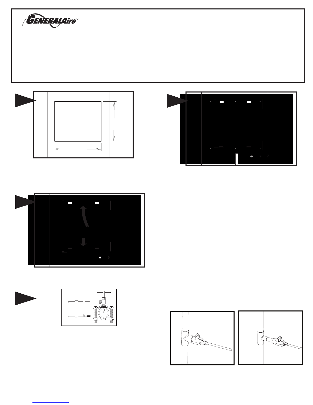
Select location on vertical surface of warm air plenum of a forced air
handling system for mounting humidifier that allows for service and
maintenance. Do not install humidifier where the blanked off ends of a
cooling coil will restrict air flow to the humidifier.
12-1/8” tall by 14-1/8” wide as shown.
2
1
2
Open cover and remove evaporator pad assembly. Humidifier chassis is
self retaining, slide top side in first then slide chassis down. Level chassis
and install eight screws.
Cut out a square section
4
Connect 1/4" water supply tube to inlet of solenoid.Connect drain hose
to 1/2" spout on humidifier cabinet using hose clamp if necessary. Run
1/2" hose to suitable drain such as floor drain, sewer or laundry sink. Be
sure hose has continuous slope and is not kinked at any point.
GCV3412 CODE VALVE INSTALLATION INSTRUCTIONS
Copper Pipe
1. Turn off water supply.
2. Clean pipe, fittings and valve with sandpaper or wire brush.
3. Apply a thin layer of flux to all surfaces to be soldered.
4. Assemble valve to pipe and/or fittings.
5. Cooling the valve by wrapping a wetted rag around the valve is
optional.
6. Heat the joints with a torch. Apply solder to each joint. Continue to
apply heat sufficient to keep solder liquid.
7. After solder has filled entire joint area, remove heat and allow joint
to cool. Do not move or disturb.
8. Slide compression nut over 1/4” copper tube followed by
compression sleeve.
9. Insert tube into valve fully and tighten nut.
10. Turn on water supply and check for leaks.
COPPER
3
Mount the self tapping saddle valve on either a cold or a hot water pipe.
A side or top mount is best to avoid clogging from pipe sediment.
Connect 1/4” O.D. tubing to the saddle valve. Copper tubing requires a
brass compression nut and brass sleeve. Plastic tubing requires a brass
insert inside the tubing in addition to a plastic ferrule and brass nut.
NOTE: DO NOT USE PLASTIC TUBING ON HOT WATER OR IN
CONTACT WITH ANY HOT PLENUM SURFACE OR DUCT.
INSTALLATION OF THIS SADDLE VALVE MUST MEET OR EXCEED
LOCAL CODES AND ORDINANCES.
FORM NO. 1000-16 REV. E
TUBING
PLASTIC
TUBING
*CODE VALVE IS INCLUDED WITH AUTOMATIC MODELS ONLY
3/4” TEE
1/2” TEE
Page 2
5
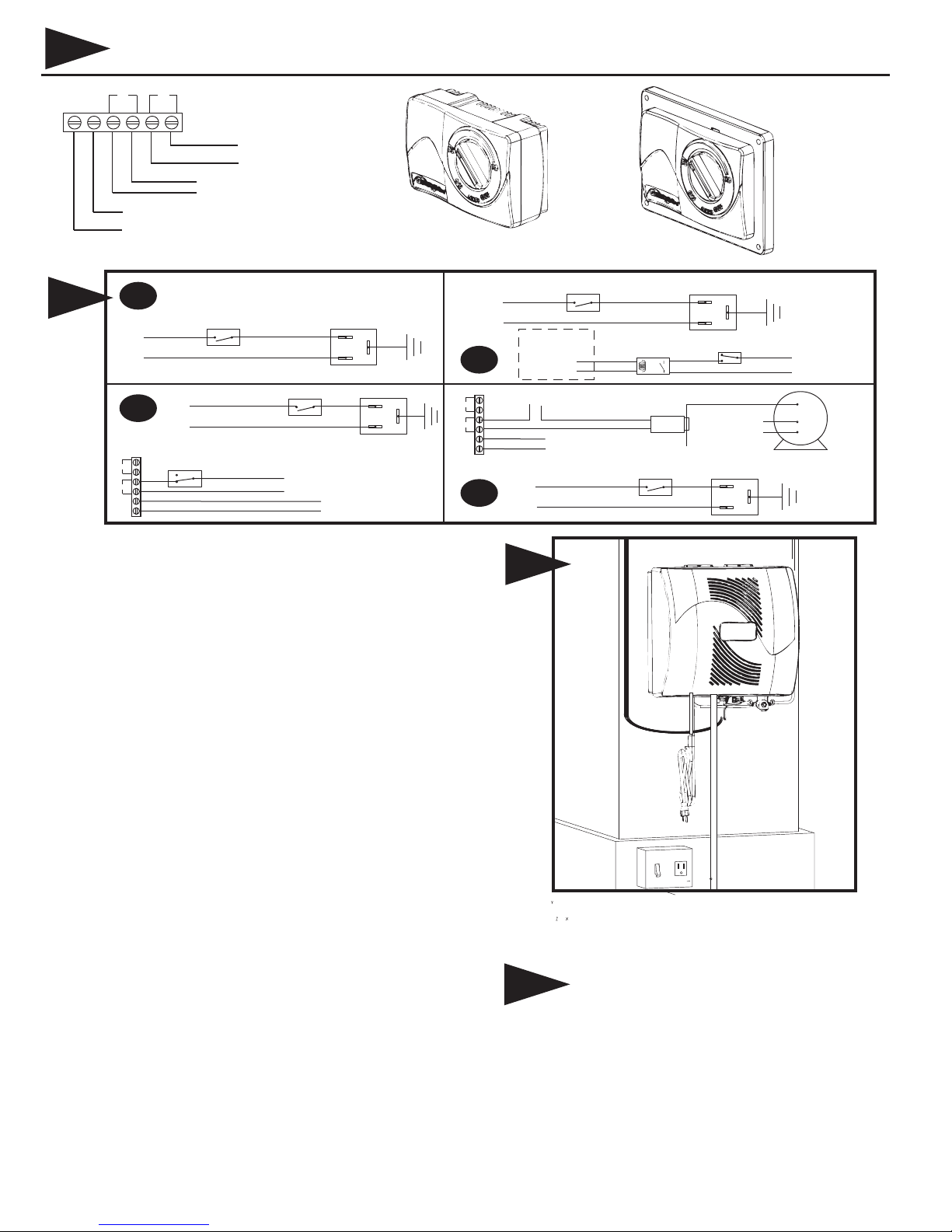
AC L
GFX3 ELECTRONIC HUMIDISTAT
AC N
SNSR
HUM
OUTDOOR TEMP. SENSOR
(NOT USED IN MANUAL MODE)
HUMIDIFIER CONTROL LEADS
(YELLOW WIRES)
24V OUTPUT FROM HUMIDIFIER (RED WIRES) OR
727-58 24 V. TRANSFORMER WITH CONSTANT POWER
OR 24 VAC POWER SUPPLY WITH CONSTANT POWER
MHX3 MANUAL HUMIDISTAT
WALL MOUNT PLATE
STANDARD FOR CANADA
OPTIONAL ACCESSORY FOR
USA
DUCT MOUNT PLATE
STANDARD FOR USA
OPTIONAL ACCESSORY FOR
CANANDA
115v.
60CY.
SNSR
HUM
AC N
AC L
6A
6C
ACC
EAC
(HOT)
C
NO
115v.
60CY.
12500 AIR
PRESSURE
SWITCH
L1
(HOT)
L2
ON-OFF
SWITCH
C
HUMIDIFIER
120v. OUTLET
ON-OFF
SWITCH
HUMIDIFIER CONTROL LEADS
(YELLOW WIRES)
HUMIDIFIER
120v. OUTLET
HUMIDISTAT POWER LEADS
(RED WIRES 24 VAC)
GRD
GRD
6
INSTRUCTIONS FOR WIRING HUMIDIFIER
NOTE: ALL WIRING SHOULD COMPLY WITH LOCAL ELECTRICAL
CODES.
6A WITH FURNACE CIRCUIT BOARD
Use with mechanical humidistat only. On furnaces with output terminals
ACC, or EAC check output voltage to determine that terminals are 115V.
Connect on-off switch in series with the hot wire. Install humidistat and
connect to yellow wires on humidifier.
SNSR
HUM
AC N
AC L
115v.
60CY.
6B
6D
7
ON-OFF
L1
(HOT)
C
HUMIDIFIER CONTROL LEADS
(YELLOW WIRES)
115v.
60CY.
SWITCH
FURNACE
CONTROL BOARD
HUM
24V.
C
60CY.
HUMIDISTAT POWER LEADS
(RED WIRES 24 VAC)
L1
(HOT)
L2
7
FIELD SUPPLIED
RELAY 24V COIL, N.O.
GA50 CURRENT
SENSING RELAY
ON-OFF
SWITCH
HUMIDIFIER
120v. OUTLET
HUMIDISTAT
NC
NO
COMMON LEAD
GRD
C
YELLOW WIRES
FROM HUMIDIFIER
MULTI
C
SPEED
HI
BLOWER
MOTOR
LO
HUMIDIFIER
120v. OUTLET
GRD
6B WITH CONSTANT POWER TO HUMIDIFIER
Use with mechanical humidistat only. Mount a junction box and 115v.
grounded outlet. Connect the on-off switch in series with the hot or black
wire. Install a field supplied 24 volt relay and attach to HUM and C on the
furnace control board. Install humidistat and connect one side to one
yellow wire on humidifier. Connect the other side of the humidistat to one
end of switch side of the relay. Connect the other switch side of the the
relay to the remaining yellow wire on humidifier. Red humidifier leads
are not used for this wiring method. Do not touch red wires together.
Damage to the humidifier will result.
6C WITH ELECTRONIC HUMIDISTAT - PRESSURE SENSING
On furnaces with a two speed blower, the humidifier and a Model 12500
Air Pressure Switch may be wired from a continuous 115 volt power
source. Install the on/off switch in series with hot or black wire and Air
Pressure Switch in series with the humidistat circuit. The Air Pressure
Switch will detect furnace operation and supply power to the humidifier
accordingly.
6D WITH ELECTRONIC HUMIDISTAT - CURRENT SENSING
On furnaces with a two speed blower, the humidifier may be wired from a
continuous 115 volt power source. Install the on/off switch in series with
the hot or black wire. Install the GA50 Current Sensing Relay in series
with the humidistat circuit. The Current Sensing Relay will detect furnace
operation and supply power to the humidifier accordingly.
Replace evaporator pad assembly and humidifier cover. Insert low voltage
six connector wiring harness from cover into chassis solenoid harness.
8
Turn on water supply and plug in power cord to check operation of
humidifier. Set humidistat to a demand setting. With the furnace off, the
solenoid valve should be closed and the humidifier fan not running. Start
the furnace, the solenoid valve should open and the humidifier fan run
when the blower or burner circuit is energized. Check flow of water
through distributor trough and evaporator pad. The standard GA4231
yellow orifice will supply approximately 3.5 GPH of water at a line water
pressure of 60 psi. For low water pressures (20-40 psi) a larger orifice
GA4299 is available to provide the same flow. Leave humidistat set at the
recommended setting.
Page 3
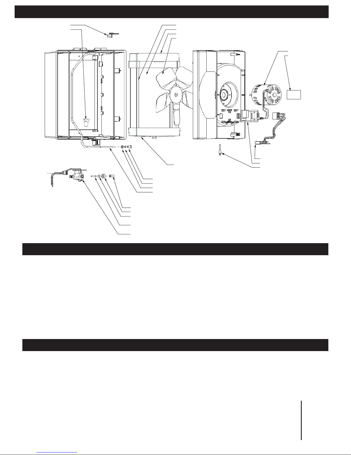
PARTS LIST FOR HUMIDIFIER
900-9 NOZZLE
900-10 SPOUT
900-40 PAD RAIL
GA19 EVAPORATOR PAD
900-15 DISTRIBUTOR TROUGH
GA4247 FAN BLADE
GA4237 MOTOR
900-71 NAMEPLATE
1000-11 HARNESS - BOARD
900-14 DRAIN PAN
GA4231 ORIFICE - YELLOW
P-190 COMPRESSION SLEEVE (PLASTIC)/P102 COPMRESSION SLEEVE (BRASS)
P-101 COMPRESSION NUT
GA4235 DISTRIBUTOR TUBE
GA4238 RELAY ASS'Y
1137-31 POWER SUPPLY CORD
This humidifier, if properly registered by the return of the warranty registration card to the manufacturer, is warranted to the consumer against defects in
materials and workmanship for a period of ten years from the date of installation. Evaporator pads, water strainers or metering orifices are not covered by
this limited warranty or any other warranties. Any other defective parts will be repaired without charge except for removal, reinstallation and
transportation costs. To obtain repair service under this limited warranty, the consumer must send the defective part or the complete humidifier to the
manufacturer.
THERE ARE NO EXPRESS WARRANTIES COVERING THIS AIR CLEANER OTHER THAN AS SET FORTH ABOVE, THE IMPLIED WARRANTIES OF
MERCHANTABILITY AND FITNESS FOR A PARTICULAR PURPOSE ARE EXPRESSLY EXCLUDED. THE MANUFACTURER ASSUMES NO
LIABILITY IN CONNECTION WITH THE INSTALLATION OR USE OF THIS PRODUCT, EXCEPT AS STATED IN THIS LIMITED WARRANTY. THE
MANUFACTURER WILL IN NO EVENT BE LIABLE FOR INCIDENTAL OR CONSEQUENTIAL DAMAGES.
This limited warranty gives you specific legal rights, and you may also have other rights which vary from state to state. Some states do not allow either
limitations on implied warranties, or exclusions from incidental or consequential damages, so the above exclusion and limitation may not apply to you.
Any questions pertaining to this limited warranty should be addressed to the manufacturer. (U.S.A.: The manufacturer has elected not to make available
the informal dispute settlement mechanism which is specified in the Magnuson-Moss Warranty Act.)
Your Humidifier is engineered to give helpful and trouble-free humidification. For maximum efficiency the following cleaning procedures should be carried
out at the end of each heating season:
1. Turn off water supply and electrical power to humidifier.
2. Remove cover, water distributor trough, evaporator pad, pad rails and drain pan. Clean excessive mineral
deposits from the distributor trough, drain pan, pad rails and humidifier cabinet. A solution of 1/2 vinegar & 1/2
water will help loosen mineral deposits.
Inspect drain hose, clean or replace as necessary.
3. Replace humidifier evaporator pad if necessary. (Part number GA19) Install trough, pad rails and drain pan.
Replace cover, reconnect electrical plug. Replace evaporator pad yearly for peak performance.
4. In heavy mineral areas or if the solenoid valve fails to function disconnect the 1/4” water supply line from the
solenoid valve. Carefully pull the strainer screen (P.N. 900-8) from the valve body (P.N. 900-6). Clean the
mineral deposits from all parts. If the orifice is clogged, it may be opened by inserting a small pin. Reinsert
the filter into the valve body.
5. Reconnect the 1/4” water line to the solenoid valve if necessary. Turn on the water supply and check all points
for leakage. The operation of the unit may be checked by starting the furnace. The humidifier operates only
when the furnace blower is running or the burner circuit is energized. The humidifier is now ready for
operation.
6. During the summer, turn off water supply and electrical power to humidifier.
P-189 TUBE SUPPORT
P-101 COMPRESSION NUT
P-102 COMPRESSION SLEEVE (BRASS) OR
P-190 COMPRESSION SLEEVE (PLASTIC)
GA4004 STRAINER SCREEN
GA4045 SOLENOID & HARNESS
ASSEMBLY
LIMITED WARRANTY
CARE AND MAINTENANCE
AT
OUTSIDE
TEMPERATURE
RECOMMENDED
SETTING
-20°F -29°C 15%
-10°F -23°C 20%
0°F -18°C 25%
+10°F -12°C
+20°F - 7°C
30%
35%
+30°F - 1°C 40%
Page 4

HOW THE HUMIDIFIER WORKS
The operating principle of the humidifier is based on the most efficient and economical means of evaporating water to the air. The heat necessary for
evaporating water is produced by the furnace.The water supply to the humidifier is controlled by the electric solenoid valve. The solenoid valve and
humidifier fan are controlled by a humidistat connected through an isolation relay. The humidistat is designed for wall mounting in the living area or surface
mounting on the return air duct.
Water flows through a strainer, is metered through an orifice to provide the proper amount of water, and is supplied to the evaporator pad by the distributor
trough. Air from the warm air plenum is pulled through the wetted evaporator pad by the humidifier fan and returned to the warm air plenum to be circulated
through the living area. Moisture is evaporated to the air passing through the evaporator pad.
Minerals are not blown into the air stream as occurs in atomizing humidifiers; they are left on the evaporator pad where a high percentage is carried off with
the waste water. When the humidifier is installed and operating, no adjustments are necessary other than setting the control knob on the humidistat to the
desired level of humidification. To turn the humidifier off, close water supply valve, switch electrical power off and turn humidistat off.
ELECTRICAL RATING: 24 VAC/ 60 Hz.
DO NOT SET RELATIVE HUMIDITY TOO HIGH DURING COLD WEATHER.
EXCESSIVE HUMIDITY MAY CAUSE CONDENSATION ON WINDOWS OR IN WALLS.
REFER TO RECOMMENDED SETTINGS AS DESCRIBED IN THE HUMIDISTAT OWNERS MANUAL.
TROUBLESHOOTING
SYMPTOMS
Humidier will not operate
Proper voltage present at solenoid
valve (24 VAC) but no water ow
Humidier runs without
furnace operation or humidier
never shuts o
Too much humidity in home and/or
condensation on windows
Where can I purchase
replacement parts?
DIAGNOSTIC STEP
1. Set thermostat to operate both furnace burner and blower. Operation may be necessary for system power.
2. Humidity level in home may be higher than humidistat setting. Increase humidity setting on humidistat.*
3 . Verify water supply is on.
4. Check for voltage at the solenoid valve. Voltage should be 24VAC. Bypass the humidistat if necessary to isolate
the solenoid valve circuit.
5. Verify wiring of humidier and humidistat.
6. Contact authorized General Aire contractor to verify voltage in and out of the relay board and replace if necessary.
1. Verify water supply is on
2. Verify metering orice is not obstructed. Very hard water with high mineral content may restrict the metering
orice in as little as one heating season. Replace metering orice if restricted. (part number GA4231)
1. Verify humidier and humidistat wiring. Humidier should operate with furnace burner or blower cycle.
1. Reduce the setting on the humidistat. Refer to CARE AND MAINTENANCE section of this manual to estimate a
humidity setting for the home based on outside temperature. *
1. Replacement parts can purchased through your authorized GeneralAire contractor or visit www.GeneralAire.com
for more information.
* Humidistat is generally located on furnace return plenum or on an inside wall in the living space.
TECHNICAL SUPPORT
USA CUSTOMERS
General Filters, Inc.
43800 Grand River Ave.
Novi, MI 48375
www.GeneralAire.com
Engineering@generalfilters.com
Toll Free (866) 476-5101
CANADIAN CUSTOMERS
Canadian General Filters, Ltd.
400 Midwest Rd.
Toronto, ON M1P3A9 Canada
www.CGFProducts.com
Sales@cgfproducts.com
Tel. (416) 757-3691
Page 5

ELITE 1000 HUMIDIFIER SPECIFICATIONS
Expected Humidity Performance Coverage in Square Feet Based on Construction Type
Model No.
Elite 570
Elite 900
Elite 1000
16-1/2”
GPD
12
17
18
Loose (0.75 AC/H)
800 sq. ft.
1115 sq. ft.
1175 sq. ft.
Average (0.50 AC/H) Tight (0.30 AC/H)
1200 sq. ft.
1650 sq. ft.
1770 sq. ft.
Humidifier Performance Baseline Criteria
Outside Design Temp 0° F (-18° C)
Outside Design R.H. 70% R.H.
Inside Design Temp. 70° F (21° C)
Inside Design R.H. 30% R.H.
Air Changes/hour (AC/H) 0.30
Ceiling Height 8 ft
Furnace Plenum Temp. 120° F (49° C)
Furnace run time for 8hr/1 day
calculating sq. ft.
2000 sq. ft.
2800 sq. ft.
3000 sq. ft.
14-1/8”
16-3/4”
17”
12-1/8”
Humidier Chassis with plenum
cut out shown as dashed lines
HUMIDIFIER PACKAGED COMPONENT ACCESSORIES
Model 1000A (GFI#5730) includes:
Humidier components: GA19 Vapor pad, Solenoid Assembly, Relay Circuit Board, Fan Motor, Fan Blades
Accessories: GFX3 Automatic Digital Humidistat, Code Valve, Saddle Valve
Model 1000M (GFI#5735) includes:
Humidier Components: GA19 Vapor Pad, Solenoid Assembly, Relay Circuit Board, Fan Motor, Fan Blades
Accessories: Manual Humidistat, Saddle Valve
Page 6

WARRANTY REGISTRATION
You may register online at www.GeneralAire.com or mail form below
Product Information:
Serial Number: _____________________________________________________________
Model: ____________________________________________________________________
Install Date: Month _______________ Day ______________ Year _____________
Owner Information:
Name: _____________________________________________________________________
Address: ___________________________________________________________________
Address 2: __________________________________________________________________
City: _______________________ State: ___________ Zip Code: ____________________
Phone: _____________________________________________________________________
Email: ______________________________________________________________________
Contractor Information:
Contractor Name: _____________________________________________________________
Address: ____________________________________________________________________
Address 2: ___________________________________________________________________
City: _____________________ State: ___________ Zip Code: _______________________
Contractor Phone: ____________________________________________________________
Contractor Email: _____________________________________________________________
R
Fresh Indoor Air Quality
Mail Form To:
General Filters, Inc
Attn: Warranty Dept.
43800 Grand River Ave.
Novi, MI 48375
cut along dashed line
cut along dashed line
USA CUSTOMERS
General Filters, Inc.
43800 Grand River Ave.
Novi, MI 48375
www.GeneralAire.com
Engineering@generalfilters.com
Toll Free (866) 476-5101
TECHNICAL SUPPORT
CANADIAN CUSTOMERS
Canadian General Filters, Ltd.
400 Midwest Rd.
Toronto, ON M1P3A9 Canada
www.CGFProducts.com
Sales@cgfproducts.com
Tel. (416) 757-3691
Page 7

R
Qualité de l’air frais intérieur
INSTALLATEUR : VEUILLEZ REMPLIR ET POSTER LA CARTE DE GARANTIE UNE
FOIS L’INSTALLATION TERMINÉE. LAISSER LES DIRECTIVES
D’INSTALLATION AU PROPRIÉTAIRE DE LA MAISON.
PRÉCAUTION : L’installateur doit être un technicien qualifié et expérimenté. Couper l’alimentation électrique
avant de commencer l’installation. Ne pas installer l’appareil dans un endroit où la température peut descendre
sous 0 °C (32 °F) ou lorsque la température du plénum dépasse 66 °C (150 °F). Pour obtenir une capacité
maximale d’évaporation, installer cet humidificateur sur un plénum d’alimentation à air chaud.
MATÉRIAUX SUPPLÉMENTAIRES POUVANT ÊTRE NÉCESSAIRES :
1. tuyau d’alimentation en plastique ou en cuivre de 6 mm (1/4 po) de diamètre
pour l’alimentation en eau chaude
2. relais du détecteur de surcharge (G.F. modèle nº GA50 suggéré)
3. boîte de dérivation, prise avec mise à la terre de
115 volts, couvercle et câblage
4. tuyau d’évacuation de 13 mm (1/2 po) de diam. int.
5. vis autotaraudeuse nº 8
SÉRIE 1000
HUMIDIFICATEUR À
ALIMENTATION CONTINUE
POUR UNE INSTALLATION SUR LA
SURFACE VERTICALE DU PLÉNUM
D’ALIMENTATION À AIR CHAUD DE
N’IMPORTE QUEL APPAREIL DE
CHAUFFAGE À AIR CHAUD PROPULSÉ
1
30,8 cm
(12-1/8 po)
35,9 cm
(14-1/8 po)
Choisir un emplacement sur la surface verticale du plénum à air chaud du
système de chauffage à air propulsé pour installer l’humidificateur qui
permette un accès facile pour les réparations et l’entretien. Ne pas installer
l’humidificateur à l’endroit où l’extrémité de la plaque d’obturation d’un
serpentin refroidisseur pourra restreindre le débit d’air vers l’humidificateur.
Découper et enlever une section carrée de 30,8 cm de hauteur x 35,9 cm
de largeur (12-1/8 po x 14-1/8 po) comme il est illustré.
2
1
2
Ouvrir le couvercle et enlever le tampon d’évaporation. Le cadre de
l’humidificateur se retient par lui-même; faire glisser d’abord la partie
supérieure, puis faire glisser le cadre vers le bas. Mettre le cadre de niveau
et visser les huit (8) vis.
TUYAU EN
3
CUIVRE
TUYAU EN
PLASTIQUE
4
Raccorder le tuyau d’alimentation en eau de 6 mm (1/4 po) à l’entrée de
la vanne électromagnétique. Raccorder le tuyau d’évacuation au bec de
13 mm (1/2 po) situé sur le boîtier de l’humidificateur en utilisant un
collier de serrage si nécessaire. Acheminer un boyau de 13 mm (1/2 po)
vers un drain adéquat, comme un drain de sol, d’égout ou d’évier de
lavage. S’assurer que le boyau est en pente continue et n’est déformé
en aucun point.
INSTRUCTIONS D’INSTALLATION DE LA VANNE-CODE GCV3412
Tuyau en cuivre
1. Couper l’alimentation en eau.
2. Nettoyer le tuyau, les raccords et la vanne avec du papier abrasif
ou une brosse métallique.
3. Appliquer une fine couche de flux sur toutes les surfaces devant
être soudées.
4. Fixer la vanne au tuyau ou aux raccords.
5. Refroidir la vanne en l’enveloppant d’un chiffon humide est une
possibilité.
6. Chauffer les joints avec un chalumeau. Souder chaque joint.
Continuer d’appliquer suffisamment de chaleur pour garder la
soudure à l’état liquide.
7. Lorsque la soudure a entièrement rempli l’espace du joint, retirer la
chaleur et laisser le joint refroidir. Éviter de déplacer ou de toucher
le joint.
8. Faire glisser un écrou à compression sur le tuyau en cuivre de
6 mm (1/4 po), puis le manchon à compression.
9. Insérer entièrement le tube dans la vanne et serrer l’écrou.
10. Ouvrir l’alimentation en eau et vérifier qu’il n’y a pas de fuites.
*LA VANNE-CODE EST FOURNIE AVEC LES MODÈLES
AUTOMATIQUES UNIQUEMENT
Installer le robinet-vanne à étrier autotaraudeur sur un tuyau d’eau
chaude ou d’eau froide. Un montage latéral ou sur le dessus est idéal
pour éviter un engorgement causé par les sédiments du tuyau.
Raccorder un tuyau d’un diam. ext. de 6 mm (1/4 po) au robinet-vanne à
étrier. Les tuyaux en cuivre exigent un écrou à compression et un
manchon en laiton. Les tuyaux en plastique exigent un insert en laiton à
l’intérieur des tuyaux ainsi qu’une virole en plastique et un écrou en
laiton.
REMARQUE : NE PAS UTILISER DE TUYAUX EN PLASTIQUE AVEC
DE L’EAU CHAUDE OU SUR UNE SURFACE DE CONTACT
CHAUDE DE PLÉNUM OU DE CONDUIT. L’INSTALLATION DE CE
ROBINET-VANNE À ÉTRIER DOIT RESPECTER OU DÉPASSER LES
EXIGENCES DES CODES LOCAUX ET AUTRES ORDONNANCES.
T de 19 mm
(3/4 po)
T de 13 mm
(1/2 po)
Page 8

5
AC L
HUMIDISTAT ÉLECTRONIQUE GFX3
AC N
SNSR
HUM
DÉTECTEUR DE TEMPÉRATURE
EXTÉRIEURE (NON UTILISÉ EN
MODE MANUEL)
FILS DE COMMANDE DE L’HUMIDIFICATEUR
(FILS JAUNES)
SORTIE DE 24 V DE L’HUMIDIFICATEUR (FILS ROUGES) OU
727-58 TRANSFORMATEUR DE 24 V AVEC ALIMENTATION CONSTANTE
OU ALIMENTATION DE 24 V c.a. AVEC ALIMENTATION CONSTANTE
HUMIDISTAT MANUEL MHX3
PLAQUE DE MONTAGE
MURAL STANDARD AU
CANADA, ACCESSOIRE EN
OPTION AUX É.-U.
PLAQUE DE MONTAGE SUR
CONDUIT STANDARD AUX
É.-U., ACCESSOIRE EN OPTION
AU CANADA
115 V
60 Hz
SNSR
HUM
AC N
AC L
6A
6C
COMMUTATEUR DE
ACC
CHAQUE
(CHAUD)
C
MARCHE-ARRÊT
L1
115 V
(CHAUD)
60 Hz
L2
12500
PRESSOSTAT D’AIR
NO
SORTIE DE 120 V
HUMIDIFICATEUR
TERRE
COMMUTATEUR DE
MARCHE-ARRÊT
C
FILS DE COMMANDE DE L’HUMIDIFICATEUR
(FILS JAUNES)
SORTIE DE 120 V
HUMIDIFICATEUR
FILS D’ALIMENTATION DE L’HUMIDISTAT
(FILS ROUGES DE 24 V c.a.)
TERRE
6
INSTRUCTIONS DE CÂBLAGE DE L’HUMIDIFICATEUR
REMARQUE : TOUT LE CÂBLAGE DOIT RESPECTER LES CODES
ÉLECTRIQUES LOCAUX.
6A AVEC CARTE DE CIRCUITS IMPRIMÉS DE L’APPAREIL
DE CHAUFFAGE
Utiliser uniquement avec un humidistat mécanique. Sur les appareils de
chauffage équipés des bornes de sortie ACC ou EAC, vérifier la tension de
sortie pour déterminer si les bornes sont de 115 V. Brancher l’interrupteur
marche-arrêt en série avec le fil chargé. Installer l’humidistat et brancher
les fils jaunes à l’humidificateur.
L1
115 V
(CHAUD)
60 Hz
C
6B
FILS DE COMMANDE DE
L’HUMIDIFICATEUR (FILS JAUNES)
SNSR
HUM
AC N
AC L
115 V
6D
60 Hz
7
COMMUTATEUR DE
MARCHE-ARRÊT
CARTE DE CIRCUITS
IMPRIMÉS DE L’APPAREIL
DE CHAUFFAGE
HUM
24 V
C
60 Hz
FILS DE COMMANDE DE L’HUMIDISTAT
(FILS ROUGES DE 24 V c.a.)
L1
(CHAUD)
L2
7
SORTIE DE
120 V HUMIDIFICATEUR
RELAIS FOURNI PAR
L’UTILISATEUR, SERPENTIN
DE 24 V, N.O.
GA50 RELAIS DU DÉTECTEUR
DE SURCHARGE
COMMUTATEUR DE
MARCHE-ARRÊT
FIL COMMUN
HUMIDISTAT
NC
NO
TERRE
C
CÂBLES JAUNES DE
L’HUMIDIFICATEUR
C
MOTEUR DE
VENTILATEUR
HAUT
À PLUSIEURS
VITESSES
BAS
SORTIE DE 120 V
HUMIDIFICATEUR
TERRE
6B AVEC ALIMENTATION CONSTANTE À L’HUMIDIFICATEUR
Utiliser uniquement avec un humidistat mécanique. Installer une boîte de
dérivation et une prise de courant avec mise à la terre de 115 V. Brancher
l’interrupteur marche-arrêt en série avec le fil chargé ou le fil noir. Installer
un relais de 24 volts fourni in situ et fixer le HUM et le C sur la carte de
circuits imprimés de l’appareil de chauffage. Installer l’humidistat et
brancher un côté à un fil jaune de l’humidificateur. Connecter l’autre côté
de l’humidistat à une extrémité du côté de l’interrupteur du relais. Brancher
l’autre côté de l’interrupteur du relais à l’autre fil jaune de l’humidificateur.
Les fils rouges de l’humidificateur ne sont pas utilisés avec cette
méthode de câblage. Ne jamais joindre les fils rouges, car
l’humidificateur pourrait subir des dommages.
6C AVEC UN HUMIDISTAT ÉLECTRONIQUE – PRESSOSTAT
Sur les appareils de chauffage équipés d’un ventilateur à deux vitesses,
l’humidificateur et un pressostat d’air modèle 12500 peuvent être branchés
à une source d’alimentation électrique continue de 115 volts. Installer
l’interrupteur marche-arrêt en série avec le fil chargé ou le fil noir et le
pressostat d’air en série avec le circuit de l’humidistat. Le pressostat d’air
détectera le fonctionnement de l’appareil de chauffage et fournira
l’alimentation électrique nécessaire à l’humidificateur.
6C AVEC UN HUMIDISTAT ÉLECTRONIQUE – DÉTECTEUR
DE SURCHARGE
Sur les appareils de chauffage équipés d’un ventilateur à deux vitesses,
l’humidificateur peut être raccordé à une source d’alimentation électrique
continue de 115 volts. Installer l’interrupteur marche-arrêt en série avec le
fil chargé ou le fil noir. Installer le relais du détecteur de surcharge GA50
en série avec le circuit de l’humidistat. Le relais du détecteur de surcharge
détectera le fonctionnement de l’appareil de chauffage et fournira
l’alimentation électrique nécessaire à l’humidificateur.
Remettre en place le tampon d’évaporation et le couvercle de
l’humidificateur. Insérer le faisceau de câblage à six connecteurs à basse
tension du couvercle au faisceau de la vanne électromagnétique du cadre.
8
Ouvrir l’alimentation en eau et brancher le cordon d’alimentation pour
vérifier le fonctionnement de l’humidificateur. Régler l’humidistat en mode
de demande. Lorsque l’appareil de chauffage est éteint, la vanne
électromagnétique doit être fermée et le ventilateur de l’humidificateur ne
doit pas fonctionner. Démarrer l’appareil de chauffage; la vanne
électromagnétique devrait s’ouvrir et le ventilateur de l’humidificateur
devrait fonctionner lors de la mise sous tension du circuit du ventilateur ou
du brûleur. Vérifier le débit d’eau passant par la goulotte du distributeur et
le tampon d’évaporation. L’orifice jaune standard GA4231 fournit environ
13,2 l/h (3,5 gal/h) d’eau à une ligne de pression d’eau de 206 kPa
(60 lb/po2). Si la pression d’eau est faible (137 à 175 kPa/20 à 40 lb/po2),
un orifice plus grand GA4299 est offert afin de fournir le même débit.
Laisser l’humidistat au réglage recommandé.
Page 9

LISTE DES PIÈCES POUR L’HUMIDIFICATEUR
900-9 GICLEUR
900-10 BUSE
900-40 RAIL DU TAMPON
GA19 TAMPON D’ÉVAPORATION
900-15 GOULOTTE DU DISTRIBUTEUR
GA4247 PALE DE VENTILATEUR
GA4237 MOTEUR
900-71 PLAQUE SIGNALÉTIQUE
1000-11 FAISCEAU - CARTE DE
900-14 BAC DE RÉCUPÉRATION
GA4231 ORIFICE - JAUNE
P-190 MANCHON DE COMPRESSION (PLASTIQUE)/P102 MANCHON DE COMPRESSION (LAITON)
P-101 ÉCROU À COMPRESSION
GA4235 TUBE DE DISTRIBUTEUR
CIRCUITS IMPRIMÉS
GA4238 ENSEMBLE DU RELAIS
1137-31 CORDON D’ALIMENTATION
Cet humidificateur, lorsqu’il est enregistré correctement en retournant la carte d’enregistrement de la garantie au fabricant, est garanti au consommateur
contre tout défaut de matériaux et de main-d’œuvre pour une période de dix (10) ans à partir de la date d’installation. Les tampons d’évaporation, les
filtres à eau ou les plaques ne sont pas couverts par cette garantie limitée ou par toute autre garantie. Toute autre pièce défectueuse sera réparée sans
frais, hormis les coûts de désinstallation, de réinstallation et de transport. Pour obtenir un service de réparation avec cette garantie limitée, le
consommateur doit envoyer la pièce défectueuse ou l’humidificateur au fabricant:
AUCUNE AUTRE GARANTIE QUE LA PRÉSENTE NE COUVRE CE FILTRE À AIR, LES GARANTIES IMPLICITES DE QUALITÉ MARCHANDE OU
D’ADAPTATION À UN USAGE PARTICULIER SONT EXPRESSÉMENT EXCLUES. LE FABRICANT NE PEUT ÊTRE TENU RESPONSABLE DE
L’INSTALLATION OU DE L’UTILISATION DE CE PRODUIT, SAUF DE LA MANIÈRE INDIQUÉE DANS LA PRÉSENTE GARANTIE LIMITÉE. LE
FABRICANT NE PEUT EN AUCUN CAS ÊTRE TENU RESPONSABLE DES DOMMAGES ACCESSOIRES OU INDIRECTS.
Cette garantie limitée vous donne des droits légaux spécifiques, et vous pouvez jouir d’autres droits, lesquels varient d’une juridiction à l’autre. Certaines
juridictions ne permettent pas de limites sur les garanties implicites ou d’exclusions pour les dommages accessoires ou indirects; les exclusions
susmentionnées peuvent donc ne pas s’appliquer dans votre cas.
Toute question relative à cette garantie limitée doit être soumise au fabricant. (É.-U. : Le fabricant a choisi de ne pas divulguer les termes de l’accord
spécifiés dans le « Magnuson-Moss Warranty Act ».)
Votre humidificateur est conçu pour fournir une humidification d’appoint sans problèmes. Pour bénéficier d’un fonctionnement maximum, suivre les
étapes de nettoyage ci-dessous à la fin de chaque saison froide:
1. Fermer l’alimentation en eau et en électricité de l’humidificateur.
2. Enlever le couvercle, la goulotte du distributeur d’eau, le tampon d’évaporation, les rails de tampon et le bac de
récupération. Nettoyer les dépôts excessifs de minéraux de la goulotte du distributeur, du bac de récupération, des
rails du tampon et du boîtier de l’humidificateur. Une solution moitié vinaigre, moitié eau aide à déloger les dépôts
de minéraux. Inspecter le tuyau de l’égouttoir, le nettoyer ou le remplacer au besoin.
3. Remplacer le tampon d’évaporation de l’humidificateur si nécessaire (réf GA19). Installer la goulotte, les rails de
tampon et le bac de récupération.
Remettre en place le couvercle, brancher la fiche électrique. Remplacer le tampon d’évaporation chaque année
pour assurer un fonctionnement optimum.
4. Dans les endroits riches en minéraux ou si la vanne électromagnétique est défaillante, déconnecter la conduite
d’alimentation en eau de 6 mm (1/4 po) de la vanne électromagnétique. Retirer avec précaution le filtre à tamis
(réf. 900-8) du corps de la vanne (réf. 900-6). Éliminer les dépôts de minéraux de toutes les pièces. Si l’orifice est
bloqué, on peut l’ouvrir en y insérant une petite tige. Réinsérer le filtre dans le corps de la vanne.
5. Raccorder la conduite d’eau de 6 mm (1/4 po) à la vanne électromagnétique au besoin. Ouvrir l’alimentation en
eau et vérifier tous les points de fuite. Le fonctionnement de l’appareil peut être vérifié en démarrant l’appareil de
chauffage. L’humidificateur fonctionne uniquement lorsque le ventilateur de l’appareil de chauffage est en marche
ou que le circuit du brûleur est activé. L’humidificateur est maintenant prêt à fonctionner.
6. Pendant la période estivale, fermer l’alimentation en eau et en électricité de l’humidificateur.
P-189 SUPPORT DU TUBE
P-101 ÉCROU À COMPRESSION
P-102 MANCHON DE COMPRESSION (LAITON) OU
P-190 MANCHON DE COMPRESSION (PLASTIQUE)
GA4004 FILTRE À TAMIS
GA4045 ENSEMBLE VANNE ÉLECTROMAGNÉTIQUE ET HARNAIS
GARANTIE LIMITÉE
SOIN ET ENTRETIEN
RÉGLAGE
RECOMMANDÉ
TEMPÉRATURE
EXTÉRIEURE
-29 °C -20 °F 15 %
-23 °C -10 °F 20 %
-18 °C 0 °F 25 %
-12 °C +10 °F 30 %
-7 °C +20 °F 35 %
-1 °C +30 °F 40 %
Page 10

FONCTIONNEMENT DE L’HUMIDIFICATEUR
Le principe de fonctionnement de l’humidificateur est basé sur la façon la plus efficace et la plus économique d’évaporer l’eau dans l’air. La chaleur
nécessaire pour l’évaporation de l’eau est produite par l’appareil de chauffage. L’alimentation en eau vers l’humidificateur est contrôlée par la vanne
électromagnétique. La vanne électromagnétique et le ventilateur de l’humidificateur sont activés par l’humidistat branché à un relais d’isolation. L’humidistat
est conçu pour une installation murale dans un endroit habité ou sur le conduit de reprise.
L’eau s’écoule par une crépine, est mesurée par un orifice pour fournir la quantité adéquate et alimente le tampon d’évaporation par la goulotte du
distributeur. L’air provenant du plénum à air chaud est aspiré à travers le tampon d’évaporation humide par le ventilateur de l’humidificateur et retourné au
plénum à air chaud afin de circuler dans l’habitation. L’humidité est évaporée dans l’air en passant par le tampon d’évaporation.
Les minéraux ne sont pas soufflés dans le courant d’air, comme c’est le cas avec les humidificateurs à pulvérisation; ils restent sur le tampon d’évaporation
où un fort pourcentage est évacué avec les eaux usées. Lorsque l’humidificateur est installé et fonctionne, aucun réglage n’est nécessaire sauf le réglage
du niveau voulu d’humidification par le bouton de commande sur l’humidistat. Pour éteindre l’humidificateur, fermer la vanne d’alimentation en eau, mettre
hors tension et fermer l’humidistat.
CARACTÉRISTIQUES ÉLECTRIQUES : 24 V c.a./60 Hz.
NE PAS RÉGLER L’HUMIDITÉ RELATIVE TROP HAUT PENDANT LA PÉRIODE HIVERNALE.
UNE HUMIDITÉ EXCESSIVE PEUT ENTRAÎNER DE LA CONDENSATION SUR LES FENÊTRES OU SUR LES MURS.
SE RÉFÉRER AUX RÉGLAGES RECOMMANDÉS DÉCRITS DANS LE MANUEL DE L’UTILISATEUR DE L’HUMIDISTAT.
DÉPANNAGE
SYMPTÔMES
L’humidicateur ne fonctionne pas
La tension au niveau de la vanne
électromagnétique est bonne (24 V c.a.),
mais l’eau ne coule pas
L’humidicateur fonctionne alors que
l’appareil de chauage est éteint, ou
l’humidicateur ne s’éteint jamais
Taux d’humidité trop élevé dans la
maison ou présence de condensation
sur les fenêtres
Où peut-on acheter des
pièces de rechange?
ÉTAPES DU DIAGNOSTIC
1. Régler le thermostat de manière à faire fonctionner l’appareil de chauage et le ventilateur; il peut être nécessaire que
ces appareils fonctionnent pour alimenter le système.
2. Le niveau d’humidité de la maison peut être plus élevé que le réglage de l’humidistat. Augmenter le réglage d’humidité
de l’humidistat.*
3. S’assurer que l’alimentation en eau est ouverte.
4. Vérier la tension au niveau de la vanne électromagnétique. La tension doit être de 24 V c.a. Contourner l’humidistat si
nécessaire pour isoler le circuit de la vanne électromagnétique.
5. Vérier le câblage de l’humidicateur et de l’humidistat.
6. Contacter un installateur GeneralAire autorisé pour qu’il vérie la tension d’entrée et de sortie de la carte de circuits
imprimés du relais et la remplace si nécessaire.
1. S’assurer que l’alimentation en eau est ouverte.
2. Vérier que l’orice de mesure n’est pas obstrué. De l’eau très dure ayant un taux élevé de minéraux peut
obstruer l’orice de mesure graduellement, dans certains cas en une seule saison. Remplacer l’orice de
mesure s’il est obstrué (réf. GA4231).
1. Vérier le câblage de l’humidicateur et de l’humidistat. L’humidicateur doit fonctionner lorsque le brûleur
ou le ventilateur de l’appareil de chauage fonctionne.
1. Réduire le réglage de l’humidistat. Consulter la section SOIN ET ENTRETIEN de ce manuel pour déterminer le réglage
de l’humidistat de votre maison en fonction de la température extérieure.*
1. Des pièces de rechange peuvent être achetées auprès de votre installateur GeneralAire autorisé ou visiter le
www.GeneralAire.com pour obtenir de plus amples informations.
*L’humidistat est généralement placé sur le plénum de retour d’air de l’appareil de chauage ou dans un mur d’un espace d’habitation.
ASSISTANCE TECHNIQUE
CLIENTS AUX É.-U.
General Filters, Inc.
43800 Grand River Ave.
Novi, MI 48375, É.-U.
www.GeneralAire.com
Engineering@generalfilters.com
Numéro sans frais : 866-476-5101
CLIENTS AU CANADA
Canadian General Filters, Ltd.
400 Midwest Rd.
Toronto, ON M1P3A9 Canada
www.CGFProducts.com
Sales@cgfproducts.com
Tél. : 416-757-3691
Page 11

CARACTÉRISTIQUES DE L’HUMIDIFICATEUR ELITE 1000
Performance d’humidité prévue selon la superficie en mètres carrés/pieds carrés et le type de construction
Nº de modèle
Elite 570
Elite 900
Elite 1000
GPD
12
17
18
41,9 cm
(16-1/2 po)
Faible (0,75 CAH)
74 m
104 m
109 m
2
/800 pi
2
/1115 pi
2
/1175 pi
2
2
2
Moyen (0,50 CAH) Élevé (0,30 CAH)
111 m2/1200 pi
153 m2/1650 pi
164 m2/1770 pi
2
2
2
Critères de base de la performance de l’humidificateur
Température de calcul – extérieure -18 °C (0 °F)
HR de calcul – extérieure HR de 70 %
Température de calcul – intérieure 21 °C (70 °F)
HR de calcul – intérieure HR de 30 %
Changements d’air/heure (CAH) 0,30
Hauteur du plafond 2,43 m (8 pi)
Température du plénum de
l’appareil de chauage 49 °C (120 °F)
Durée de fonctionnement de l’appareil
de chauage pour calculer la supercie 8 h/jour
186 m2/2000 pi
260 m2/2800 pi
279 m2/3000 pi
35,9 cm
(14-1/8 po)
2
2
2
ACCESSOIRES DES COMPOSANTS DE L’HUMIDIFICATEUR EMBALLÉ
Le modèle 1000A (GFI nº 5730) inclut :
Composants de l’humidicateur : GA19 tampon d’évaporation, ensemble de la vanne électromagnétique, carte de circuits
imprimés du relais, moteur de ventilateur, pales du ventilateur
Accessoires : GFX3 Humidistat numérique automatique, vanne-code, vanne à étrier
Le modèle 1000M (GFI nº 5735) inclut :
Composants de l’humidicateur : GA19 tampon d’évaporation, ensemble de la vanne électromagnétique, carte de circuits
imprimés du relais, moteur de ventilateur, pales du ventilateur
Accessoires : Humidistat manuel, vanne à étrier
42,5 cm
(16-3/4 po)
43,1 cm
(17 po)
30,8 cm
(12-1/8 po)
Cadre de l’humidicateur avec la découpe
du plénum illustrée en lignes pointillées
Page 12

ENREGISTREMENT DE LA GARANTIE
Le produit peut être enregistré en ligne au www.GeneralAire.com
ou par la poste en envoyant le formulaire ci-dessous
Renseignements sur le produit :
Numéro de série : ____________________________________________________________
Modèle : ___________________________________________________________________
Date d’installation : Mois _______________ Jour ______________ Année ____________
Renseignements sur le propriétaire :
Nom : _____________________________________________________________________
Adresse : __________________________________________________________________
Adresse 2 : ________________________________________________________________
Ville : ____________________ État/Province : ___________ Code postal : ___________
Téléphone : ________________________________________________________________
Courriel : __________________________________________________________________
Renseignements sur l’installateur :
Nom : _____________________________________________________________________
Adresse : __________________________________________________________________
Adresse 2 : ________________________________________________________________
Ville : ____________________ État/Province : _____________ Code postal : _________
Téléphone : ________________________________________________________________
Courriel : __________________________________________________________________
R
Qualité de l’air frais intérieur
Poster le formulaire à :
General Filters, Inc
Attn: Warranty Dept.
43800 Grand River Ave.
Novi, MI 48375, É.-U.
découper le long de la ligne pointillée
découper le long de la ligne pointillée
CLIENTS AUX É.-U.
General Filters, Inc.
43800 Grand River Ave.
Novi, MI 48375, É.-U.
www.GeneralAire.com
Engineering@generalfilters.com
Numéro sans frais : 866-476-5101
ASSISTANCE TECHNIQUE
CLIENTS AU CANADA
Canadian General Filters, Ltd.
400 Midwest Rd.
Toronto, ON M1P3A9 Canada
www.CGFProducts.com
Sales@cgfproducts.com
Tél. : 416-757-3691
 Loading...