

Page 1

Installation, Operating and Maintenance Manual
Read And Save These Instructions
Page 2

IMPORTANT WARNINGS
BEFORE INSTALLING OR HANDLING THE APPLIANCE PLEASE CAREFULLY READ
AND FOLLOW THE INSTRUCTIONS AND SAFETY STANDARDS DESCRIBED IN THIS
MANUAL AND ILLUSTRATED BY THE LABELS ON THE MACHINE.
This humidifier produces non-pressurized steam using electrodes immersed in the water
contained in the plastic steam generator cylinder. The electrodes pass electrical current through
the water, to produce steam.
The quality of the water used affects the ability of electrical current to pass through the water, so
the appliance may be supplied with untreated water, as long as this is drinkable and not
demineralized. (Use of softened water is not recommended.)
This appliance has been designed exclusively to directly humidify rooms or ducts, using the
distribution system supplied. It is suitable for this purpose as long as: the installation, use and
maintenance operations are carried out according to the instructions contained in this manual and
on the labels applied internally and externally.
The conditions of the environment and the power supply voltage must comply with the specified
values. All other uses and modifications made to the device which are not authorized by the
manufacturer are considered incorrect. Liability for injury or damage caused by the incorrect use
of the device lies exclusively with the user.
Please note that the machine contains powered electrical devices and hot surfaces. All service
and/or maintenance operations must be performed by qualified personnel who are aware of the
necessary precautions and are capable of performing the operations correctly. Disconnect the
machine from the main power supply before accessing any internal parts. Local safety standards
in force must be applied in all cases.
The humidifier is made up of metallic and plastic parts. All parts must be disposed of in
accordance to local standards on waste disposal.
This product is warranted for 2 years from the date of installation, or 2 years and 1 month (see
page 23 and warranty card) from the date of original shipment, whichever comes first. This
warranty does not cover consumable parts, such as the steam cylinder. Full warranty information
is on a separate registration card supplied with this appliance.
WARNING: Your humidifier requires water to operate. Do NOT mount it above materials or
machinery that could be damaged if a leak occurs. General Filters, Inc. assumes no responsibility
for consequential or inconsequential damage as a result of any leaks.
2
Page 3

Installation, Operating and Maintenance Manual
Table of Contents
1: REMOVE HUMIDIFIER FROM BOX AND OPEN............................................................................. 4
2: MOUNTING THE HUMIDIFIER............................................................................................................ 5
POSITIONING.................................................................................................................................................. 5
OUNTING..................................................................................................................................................... 5
M
3: STEAM DISTRIBUTION ......................................................................................................................... 6
R
OOM DISTRIBUTION..................................................................................................................................... 6
DUCT DISTRIBUTION...................................................................................................................................... 7
STEAM HOSE INSTALLATION.......................................................................................................................... 7
4: PLUMBING................................................................................................................................................ 9
CONNECT WATER DRAIN...............................................................................................................................9
CONNECT WATER FEED................................................................................................................................. 9
5: POWER WIRING.................................................................................................................................... 10
6: CONTROLS WIRING............................................................................................................................. 11
MOUNT THE HUMIDISTAT............................................................................................................................ 11
MOUNT 12500 AIR PRESSURE SWITCH (DS-20 ONLY)................................................................................ 11
CONNECT HOSES. CONNECT HOSE TO SUPPLY PLENUM PROBE. TRIM HOSE TO
LENGTH AND CONNECT TO HIGH PRESSURE INLET TOWARD REAR OF SWITCH.
CONNECT RETURN PLENUM PROBE TO LOW PRESSURE INLET TOWARD FRONT OF
SWITCH........................................................................................................................................................ 11
WIRE THE CONTROLS .................................................................................................................................. 12
7: START-UP AND SHUT-DOWN ............................................................................................................ 13
FIRST START-UP ........................................................................................................................................... 13
STARTING THE UNIT ..................................................................................................................................... 13
HUT-DOWN................................................................................................................................................ 14
S
8. OPERATING PRINCIPLE AND OTHER FUNCTIONS.................................................................... 15
OPERATING PRINCIPLE ................................................................................................................................. 15
9. ALARMS, TROUBLESHOOTING........................................................................................................ 16
10. MAINTENANCE AND SPARE PARTS.............................................................................................. 18
REPLACING THE CYLINDER ......................................................................................................................... 18
MAINTENANCE OF THE OTHER HYDRAULIC COMPONENTS......................................................................... 18
CLEANING THE FILL VALVE......................................................................................................................... 18
C
LEANING THE DRAIN VALVE..................................................................................................................... 19
HYDRAULIC PARTS ...................................................................................................................................... 19
PARE PARTS................................................................................................................................................ 20
S
11. WIRING DIAGRAM.............................................................................................................................. 21
12. TECHNICAL SPECIFICATIONS ....................................................................................................... 22
D
IMENSIONS AND WEIGHTS .......................................................................................................................... 22
3
Page 4

1: Remove Humidifier
From Box And Open
Twist GeneralAire brand badge on the front
cover of the cabinet to uncover the hidden
capture screw underneath the right side.
Remove capture screw using a phillips
screwdriver. (take care not to lose the screw)
Lift cabinet front cover upward about 1” and then
pull forward to remove.
Your Elite Steam humidifier will consist of:
For duct mounted applications:
1 - Steam humidifier unit
1 - Duct steam nozzle
6' - 7/8" ID steam hose
2 - Steam hose clamps
7' - 5/16" ID condensate hose
1 - Condensate hose clamp
1 – 800 UST Saddle valve kit
1 – Wall / Duct Mount Humidistat
1 – 12500 Air Pressure Switch
1 – Water supply tube kit
3 - Screws and anchors
1 - Fill connector
1 – 10’ coil low voltage wire
For room mounted applications:
1 - Steam humidifier unit with blower attached
1 – 800 UST Saddle valve kit
1 – Wall / Duct Mount Humidistat
1 – Water supply tube kit
3 - Screws and anchors
1 - Fill connector
1 – 10’ coil low voltage wire
IMPORTANT: BEFORE beginning installation:
Check for shipping damage to cartons. Mark the shipping waybill accordingly.
Open cartons and check for any hidden damage. Mark the shipping waybill accordingly.
Check packing slip to insure all items have been received. Notify General Filters, Inc. within one
week of any shortages or damaged parts.
4
Page 5

Installation, Operating and Maintenance Manual
2: Mounting The Humidifier
Positioning
The humidifier unit should be mounted as close as
possible to the steam distributor nozzle or blower unit to
minimize steam hose length and condensate losses.
The unit has been designed for wall-mounting, and the
wall must be able to support the weight of the unit in
normal operating conditions (See bottom of page).
The metal cabinet of the humidifier heats up during
operation, and the rear part in contact with the wall may
reach temperatures of over 140°F. Make sure the
humidifier is mounted level and plumb, and that the
minimum clearances, as shown at right, are maintained
to allow room for maintenance operations and ventilation.
Mounting
The humidifier must be wall-mounted using three screws: two upper
screws, for fastening the support bracket, and one lower, central
screw, to fasten the unit into place. To the right is the template for the
mounting holes.
Fasten the bracket supplied with the humidifier to the wall (see
below); making sure that it is level. If the unit is to be mounted to a
block wall, use the plastic screw anchors (5/16”) and screws (3/16” x
2”) supplied.
Hang the humidifier on the bracket using the mating bracket located
on the top edge of the back of the humidifier. Fasten the humidifier
to the wall using the central hole in the rear part of the base; this can
be easily reached from underneath the unit.
Height: 24-3/8”
Width: 14-1/8”
Depth: 10-1/4”
Weight dry: 29.7 lbs.
Weight wet: 36.4 lbs.
5
Page 6

3: Steam Distribution
Room Distribution
The room distribution unit is used to distribute the steam directly into the room, and is supplied
premounted to the top of the humidifier.
The drawing shows the minimum distances required to prevent humidified air from coming into
contact with persons, or surfaces before the steam has been totally absorbed by the air.
6
Page 7

Installation, Operating and Maintenance Manual
Duct Distribution
If a duct steam distribution nozzle is to be used, selected an accessible location on the duct,
allowing at least 18” of straight duct (no elbows or obstructions) after the point where the nozzle will
be installed and the clearances can be maintained as per the following drawings.
To mount the steam distributor nozzle, cut or drill a 2-1/2” hole in the duct. Apply caulk to the
mounting plate of the nozzle. Attach the nozzle to the duct using 4 #10 sheet metal screws
(supplied). Nozzle must be level with condensate outlet to bottom.
Steam Hose Installation
The humidifier must be connected to the distributor nozzle
using the GeneralAire hose supplied or other hose suitable
for use with steam and condensate. The use of unsuitable
tubing may cause weakening and cracking and consequently
steam leaks.
Installation of the steam hose is absolutely critical.
95% of all operational problems are traced back to
improper hose installation.
Steam must flow through the hose, and condensate must flow back. Avoid any kinks, sags or
areas where condensate can become trapped as it will impede the free flow of steam, putting
pressure on the humidifier cylinder.
The steam hose must slope 20% up and away from the humidifier or 5% down and away.
7
Page 8
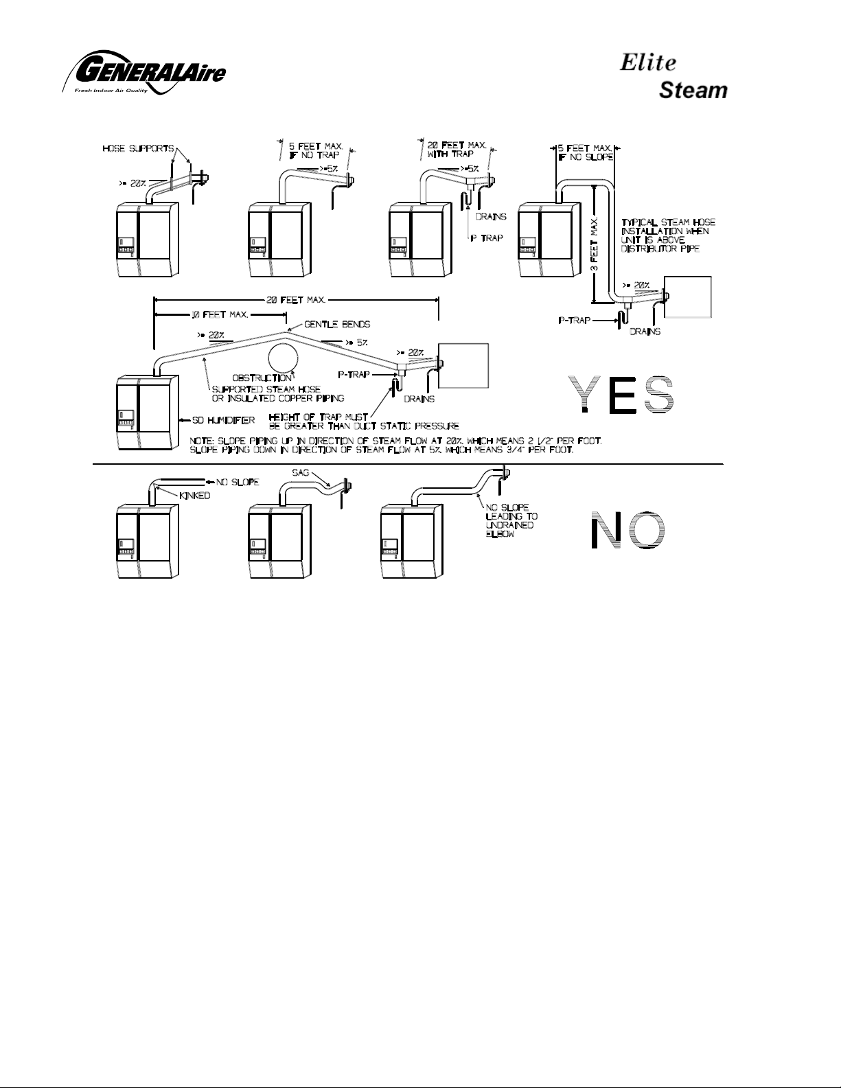
If necessary, support the steam hose using braces or other
supports. DO NOT try to pipe the steam to two different
ducts or air handlers.
The condensate hose should be trapped as shown in the two
drawings above. This is to prevent steam from flowing
through it. The condensate is wasted, either to the nipple on
top of the humidifier, or to a separate drain. DO NOT put
condensate into the humidifier fill cup.
Hose clamps are provided for the 7/8” I.D. steam hose as
well as for the 5/16” condensate hose. DO NOT reduce the
size of the steam hose, use valves or otherwise restrict
the free steam flow.
WARNING: the length of the steam hose should be less than 12 feet.
8
Page 9

Installation, Operating and Maintenance Manual
4: Plumbing
Connect Water Drain
The humidifier periodically drains some hot water to
remove mineral build-up in the steam cylinder. This
water is generally in the range of 140 to 200°F, so the
drain piping must be CPVC or copper.
The drain line should be 1-1/2” diameter CPVC. Slip the
1-1/2” pipe over the drain outlet on the bottom of the
humidifier as shown at right. Do not glue to the
humidifier.
A trap must be used in the drain line directly below the
humidifier to prevent flash steam from rising into the
humidifier unit and condensing on components.
WARNING: Failure to install a drain trap as
instructed will void the warranty.
Instant maximum drain water flow = 0.40 gpm
Connect Water Feed
A plastic and brass quick connect fitting is supplied for
connection of the water feed line. This fitting includes a
¼” O.D. compression fitting which mates to standard ¼”
O.D. plastic or copper tubing.
Inside the fill valve connection is a plastic strainer which
must be removed for periodic maintenance. Make sure
that your installation will allow the plastic fitting to be
removed for maintenance.
WARNING: Hand tighten only.
DO NOT USE DEMINERALIZED WATER.
Instant maximum feed water flow = 0.30 gpm
9
Page 10

5: Power Wiring
Feed power wiring through strain relief in bottom of
humidifier and tighten around wiring cable.
Connect power wires into terminals N and L. A green/yellow
ground terminal (which is also the chassis ground) is provided
for connection of the ground wire.
Power supply Rated specifications
Voltage (1)
(V - Type)
230 – 1 N 10.4 2.40 7 12 AWG 15A / quick blow
current (2)
(A)
power (2)
(kW)
Steam output
(lbs/hr)
wire size
power fuses (4)
(A / type)
wiring diagram
See end of
manual
10
Page 11

Installation, Operating and Maintenance Manual
6: Controls Wiring
Mount The Humidistat
Please refer to the installation Instructions included with the Humidistat.
Mount 12500 Air Pressure Switch (DS-20 Only)
Mount Air Flow Switch on a vertical surface. Switch must be oriented vertically with the hose
connections pointed down. Do not mount switch on or in warm air plenum. Use care when
locating mounting holes so as not to damage furnace electronics, fuel lines, combustion chamber,
etc.
Mount Plenum Probes. Select locations on supply and return plenums so length of supplied hose
will be sufficient and does not kink. Drill ¼” hole and insert long end of probe into duct. Use two
sheet metal screws to secure probe.
Connect hoses. Connect hose to supply plenum probe. Trim hose to length and connect to high
pressure inlet toward rear of switch. Connect return plenum probe to low pressure inlet toward
front of switch.
11
Page 12

Wire The Controls
Two pigtail wires are provided inside the
electrical compartment of the humidifier. This
“AB” to “AB” circuit is the low-voltage control
for the humidistat and air pressure switch.
The humidifier will run when the AB-AB
Circuit is completed.
24 volt A.C. to power the E1 Humidistat may
be pulled from the “G” and “GND” terminals.
The AB-AB circuit is completed through the
12500 Pressure Switch (“NO”, “C” terminals)
and the E1 Humidistat (“OUT” terminals).
If it is desired for the humidifier to activate the
heating fan during a call for humidity use the
second wiring scheme below.
terminal function electrical specifications
+VR
SET
AB
AB
G
GND
Enabling jumper external N/O contact; R
Input from humidistat remote
enabling input
24V AC power supply for E1
Humidistat and relay
external N/O contact; R
Output V
=50 ; V
max
=50 ; V
max
=24Vac; LOAD
max
=10Vdc; I
max
=24Vdc; I
max
=500mA ac
max
12
=1mAdc
max
=10mAdc
max
Page 13

Installation, Operating and Maintenance Manual
7: Start-Up And Shut-Down
Important Warnings:
Before starting, check that the humidifier is in perfect condition, that there are no water
leaks and that the electrical parts are dry;
Do not connect power if the humidifier is damaged or even partially wet;
When installation is completed, flush the supply tubing for several minutes by piping water
directly into the drain, without sending it into the humidifier. This will eliminate any scale
or construction dirt that may cause foam when boiling.
Before starting the humidifier, check the following:
The water, electrical and steam distribution connections have been made according to the
instructions contained in this manual;
The water shut-off valve to the humidifier is open;
The external main power fuses or breakers are installed and intact;
All wiring connections to the unit and inside the unit are tight;
The pigtail control wires are connected properly to the humidistat and air flow switch and
that these are both closed indicating a demand for humidity and air flow in the duct;
The steam hose is clear and properly sloped;
The condensate return hose from the distributor is installed, trapped and open to drain;
The drain tubing is correctly connected, trapped and open to drain;
First start-up
When first starting the unit with a clean empty cylinder, the humidifier will operate using a special
start-up routine designed to concentrate the minerals in the water for maximum efficiency. If the
water is very good (low mineral content) this process may take up to several hours before the full
rated production of steam is reached.
Starting the unit
On the right side, rear of the humidifier cabinet are two rocker switches. One is marked I and O;
this is the On/Off switch (I=On, O=Off). Next to it is the manual drain switch.
To start the humidifier, simply press the top of the On switch (I). If the unit does not
start operating, then check the control devices wired between the pigtail control wires
to be sure they are closed, completing the control circuit.
ON
13
Page 14

Once started, the LEDs on the control panel at the bottom
front of the humidifier will glow to indicate operation
LED Position Means
Green Left Power on
Yellow Center Humidification in progress
Red Right Signals and alarms. These are indicated by specific flashes.
Sequence Of LED Flashes On Start-Up
On start-up, the humidifier performs a sequence of flashes of the LEDs on the front panel. Please
note that the green LED remains on for the entire time the machine is on, irrespective of the
operating status. The sequence consists of the following operations:
1. Power connected: the yellow and red LEDs remain off for 1 second;
2. Initialization: the yellow and red LEDs flash a number of times to indicate the version of the
program that the board is configured with; this occurs once each time the machine is started;
a. First the yellow LED - the number of flashes indicates the tens (0=no flash);
b. Then the red LED - the number of flashes indicates the units (0=no flash); example:
version 1.1: 1 flash of the yellow LED, then 1 flash of the red LED;
c. Once the sequence of flashes corresponding to the unit is completed, the LEDs remain
off for 3 seconds, followed by the start of operation.
3. Operation: the humidifier starts operation; the yellow LED indicates that production is in
progress, as shown by the following table:
Yellow LED Production
Off 0%
1 flash 1% to 19%
2 flashes 20% to 29%
3 flashes 30% to 39%
… …
9 flashes 90% to 99%
Always on 100%
Remark: the transient production is signalled by short flashes: on and off twice in 1 second; each
sequence of flashes repeats continuously and, between one sequence and the next one, the yellow
LED stays off for 3 seconds.
Indication Of An Alarm
When an alarm occurs, the red LED starts to flash. The number of the flashes followed by a pause
indicates specific alarms. See ALARMS, TROUBLESHOOTING.
Shut-Down
During seasonal shut-down or shut-down for maintenance, the humidifier should be placed out-ofservice.
14
Page 15

Installation, Operating and Maintenance Manual
If during a shut-down the cylinder needs to be emptied, (which is recommended for seasonal
shut down) press the drain button (down arrow) and hold until the water has been completely
emptied, before disconnecting power from the unit.
In the event of a malfunction of the drain valve, the cylinder can be emptied by lifting it from the
bottom connection and slowly pouring the water into the drain pan.
Press the bottom of the On/Off rocker switch (O) and check that the
LEDs on the display panel are all out.
open the main power switch to the humidifier;
close the water shut-off valve to the humidifier.
OFF
8. Operating Principle And Other Functions
Operating principle
On a call for humidity, a power contactor closes
and sends power to the electrodes (11) in the
plastic cylinder (10). After a short delay, the fill
valve (1) opens and water flows into the fill cup
(3 to 7), covering the conductivity probes (6).
The controller reads the water conductivity and
remembers it. Water then flows through the
tubing (4) and into the bottom of the cylinder
(12) by gravity. As it rises over the electrodes
(11), electric current begins to flow through the
water and the water warms. Eventually the
water begins to boil into steam, which exits the
cylinder (9) into the steam hose and then into
the air duct. The steam output is directly
proportional to the amount of electrode covered
by water. If the amperage rises too high, the
controller will open the drain valve (14) and
drain off some water. As water is boiled off, the
fill valve (1) will open and replace it. As water is
boiled off, mineral will begin to build up in the
cylinder, so periodically the controller will open the drain valve (14) and drain some of the mineral
laden water away and replace it with fresh water. If the water rises too high, or foaming occurs,
this is detected by the cylinder full electrodes (8).
Anti-foam procedure
Some types of supply water foam during operation. When the humidifier detects the presence of
foam, a special drain/fill procedure is activated to eliminate the foam. The procedure consists of
repeated draining, and in more critical situations complete draining of the cylinder.
Automatic draining of the cylinder for extended shut-down
If the humidifier remains powered but there is no call for humidity for a period of more than 7 days,
the water contained inside the cylinder is completely drained. This function prevents the corrosion
and rusting of the electrodes.
15
Page 16

9. Alarms, Troubleshooting
Alarms are indicated on the front display panel by a sequence of flashes of the red alarm LED. In the
event of more than one alarm, these are indicated in sequence. Even if no longer active, the
alarm status continues to be displayed by the flashing of the LED and the operation of the
humidifier is stopped while the alarm is still present. To clear the inactive alarms, the humidifier
must be turned off, and then on again. Active alarms cannot be reset by restarting the
machine.
LED flash modes: slow flashes - 1 flash every 2 seconds; quick flashes - 2 flashes per second;
the signals are repeated continuously, and the LED stays off for 3 seconds between one signal
and the next.
Display Causes Solution Action
Current overload in
the electrodes;
probable fault in the
2 quick flashes
red LED
3 quick flashes
red LED
2 slow flashes
red LED
3 slow flashes
red LED
4 slow flashes
red LED
5 slow flashes
red LED
6 slow flashes
or 3 quick
flashes
red LED
9 slow flashes
electrodes or water
temporarily too
conductive
(especially on restart after a brief
pause)
High level is
indicated but no
amperage draw is
present
End of cylinder life Turn the machine off and replace the cylinder
No water
Excessive reduction
in steam output
Drain malfunction
Internal memory
error
Cylinder full with
humidifier off-duty
Drain part of the water and re-start
With the machine off and disconnected from the main power
supply, check the condition of the cylinder and the electrical
connections
Check that the supply water tubing to the humidifier and the
internal tubing are not blocked or bent and that there is proper
pressure;
Check the operation of the supply valve;
Check that the steam outlet does not have excessive backpressure, preventing the flow of water into the cylinder by
gravity;
Check that the steam outlet hose is not choked or that there
are pockets of condensate
End cylinder life or alternatively water with excessive foam
Check the water drain circuits and the correct operation of the
drain valve
Contact the Dealer
Turn off the machine and check whether the full electrovalve
leaks or there is some condensate entering the cylinder from
the steam distributor
Total
shut-
down
Total
shut-
down
Signal
only
Total
shut-
down
Total
shut-
down
Total
shut-
down
Total
shut-
down
Total
shutdown
16
Page 17

Installation, Operating and Maintenance Manual
Troubleshooting table
Problem Causes Solution
The humidifier does
not turn on
The humidifier does
not start operation
The humidifier fills
with water without
producing steam
Breaker opens
The humidifier wets
the duct
The humidifier wets
the floor below
1. No electrical power;
2. On/Off switch of the humidifier in Off
position (O);
3. Improper connection;
4. Blown fuses;
5. Transformer fault;
6. Humidistat or air flow switch not closed
1. Humidistat or air flow switch open;
2. The humidistat has not been connected
correctly;
3. Humidistat fault
1. Too much backpressure in steam hose;
2. Cylinder drain screen blocked;
3. Lime scale in the fill cup;
4. Drain valve malfunction
Circuit breaker is under-rated Check that the thermal-magnetic overload
1. The distributor is not installed correctly;
2. Humidifier over-sized;
3. Humidifier active when the fan in the
duct is off
1. The humidifier drain is blocked;
2. The supply water or overflow circuit has
leaks;
3. The steam outlet pipe is not properly
fastened to the cylinder
1. Check the external fuses and breakers
and for power at the humidifier;
2. Turn the On/Off switch On (I);
3. Check that the power wires are properly
inserted in the terminal block;
4. Check the condition of fuses f1/f2/f3;
5. Check that the voltage across the
secondary winding of the transformer is
24vac
6. Jump out airflow & humidistat
1. Fix or replace humidistat or air flow switch;
2. Check the external wiring
1. Check that the steam outlet pipe is not
bent or choked;
2. Clean the filter;
3. Clean the fill cup;
4. Check for the presence of 24vac at the
drain electrovalve and/or replace drain
electrovalve
switch is rated for a current of at least 1.5
times the rated current of the humidifier
1. Check that the steam distributor is
installed correctly;
2. Change humidifier model;
3. Check the connection and condition of the
airflow switch
1. Clean the drain in the bottom tank;
2. Check the entire water circuit;
3. Check the fastening of the pipe clamps on
the steam outlet
17
Page 18

10. Maintenance And Spare Parts
Replacing The Cylinder
WARNING: the cylinder may be hot. Allow it to cool before touching it or use protective
gloves.
To access the cylinder:
Completely drain the water contained in the cylinder (see Shut-down);
Turn the humidifier off and open the external disconnect;
Open and remove the cover (see Removal and reassembly of the front cover);
Remove the steam hose from the cylinder outlet;
Disconnect the electrical connections from the power and high level electrodes;
Unlock the cylinder from its holding arm and lift it up to remove it;
Insert the new cylinder in the humidifier by performing the previous operations in reverse.
(Make sure electric connection is tight, failure to do so may cause equipment damage, fire, or
bodily injury.)
Maintenance Of The Other Hydraulic Components
WARNINGS:
• When cleaning the plastic components do not use detergents or solvents;
• Scale can be removed using a solution of 5% phosphoric acid and then rinsing with
water (Lime-A-Way or CLR may also be used).
The steam humidifier has just one part that requires periodical replacement: the steam
production cylinder. This operation is necessary when mineral deposits that form inside the
cylinder prevent the sufficient passage of current. This situation is displayed by the control with an
alarm signal. The frequency of this operation depends on the supply water: the higher the content
of mineral, the more frequently the cylinder will need
replacing.
Cleaning The Fill valve
After shutdown and removal of the steam cylinder, shut off
the water supply to the humidifier, disconnect the water
supply and remove the fill valve from the humidifier.
Remove the inlet strainer by reaching up into the fill valve
inlet with a pair of needle nose pliers and pulling out the
strainer by its tab. Clean the fill valve and inlet strainer using
the same solution as used to clean the steam humidifier, but DO NOT soak the solenoid coil in
fluid. Reinstall the fill valve.
WARNING: When cleaning the fill valve, do NOT poke or probe flow regulator with any
object which may enlarge the orifice. The flow regulator must meter water flow precisely or
shortened cylinder life may result.
18
Page 19

Installation, Operating and Maintenance Manual
Cleaning The Drain Valve
Remove the drain valve group and disassemble it.
Clean all parts in the same way as the fill valve,
reassemble and reinstall.
After cleaning and reassembly, restart your humidifier
according to the Startup Instructions contained in this
manual.
Hydraulic Parts
No. Description
1 Fastening o-ring for s/d (supply - drain)
manifold
2 Supply/drain manifold
3 Water fill valve
4 Drain valve
5 Fill cup supply hose
6 Cylinder supply hose
7 Overflow hose
8 Fill cup with conductivity probes
9 Base / drain pan
Clean the drain pan and fill cup of any deposits and check
that the water flows freely from the fill cup to the drain.
Check that there are no blockages or solid particles and
that the conductivity measuring electrodes are clean.
Remove any impurities and rinse.
See spare parts list on page 20
19
Page 20

Fuses in the auxiliary circuits
The dimensions of these are 10.3x38 mm and are contained in cartridge-type fuse holders; to
check the condition of the fuses, check continuity using a tester.
Use fuses with the settings indicated in the following table.
Fuses 1- 2
Fuse 3 * 2A slow blow
* 5 x 20 mm, only on the control board.
Spare parts
Duct Steam Nozzle 20-1
Steam Hose 20-2
Condensate Hose 20-3
Fill Connector 20-4
Fill Cup 20-5
Drain Valve 20-6
Internal Tubing Kit 20-7
Power Transformer 208-230/24v. 20-8
Control board with LED support panel 20-9
Fill Valve 20-10
Steam Cylinder 20-14
Self Tapping Saddle Valve Kit 800-UST
Water Supply Tubing Kit 747-38
Humidistat H-86
Air Pressure Switch 12500
1A fast-blow
Description Code
20
Page 21

Installation, Operating and Maintenance Manual
11. Wiring Diagram
RS-20 ONLY
FAN
LNGND
F2
GO
TAM
L1
RELAY 2
F1
MS
G
TP
Drain
Switch
Manual
TP
ON
GND
FUSE
DR
EV2
G
EV1
EV3
CONTROL
INPUT
POWER
G
LS
MODULE
LS
CS
CS
EXTERNAL
SIGNALS
ID2
ID1
GND
SCR-
SCR+
V
DIP
Switch
G
R
{
RELAY 1
AB
N1
SET
+VR
JUMPER
FACTORY
AB
GND
Module
ON/OFF
REMOTE
Display
CS
FILL
CUP
LS
UNIT
STEAM
BOILER
FILL
DRAIN
VALVE
VALVE
21
Page 22

12. Technical Specifications
Model
rated power supply voltage (Vac) 230
steam connection (φ inches)
steam outlet pressure limits (inches w.c.) 0 to 8” w.c.
operating conditions
storage conditions
index of protection IP20
auxiliary voltage / frequency (V - Hz) 24 Vac, 50/60 Hz
maximum auxiliary power (VA) 25 VA
instant steam production
power consumed at rated voltage (kW) 2.40 kW 2.40 kW
duct steam nozzle High
steam hose High temperature EPDM
water pressure 15 to 150 psi
water conductivity 125 to 1250 micromhos
room blower unit air volume N/A 100 CFM
room blower unit power consumption N/A 30 Watts
room blower unit noise level N/A 50 dBA
(1) the average steam production is affected by factors such as: ambient temperature, water quality, steam distribution system
(1)
(lbs/hr)
DS-20
Duct Kit
7/8”
temperature 34 to 104 °F,
humidity 10 to 60% RH
temperature 14 to 158 °F,
humidity 5 to 95% RH
noncondensing
7 lbs/hr 7 lbs/hr
temperature
plastic
RS-20
Fan Kit
N/A
Dimensions and weights
A 14-1/8”
B 10-1/4”
C 24-3/8”
packaged 40 lbs.
empty 29.7 lbs.
Wet * 36.4 lbs.
*: in normal operating conditions,
filled wi t h wa t er
RS-20 (due to
blower)
add 9” high
add 10 lbs.
22
A
B
C
Page 23

Installation, Operating and Maintenance Manual
LIMITED WARRANTY
The DS-20 and RS-20 humidifiers, if properly registered by the return of the attached warranty
registration to General Filters, Inc., are warranted to the consumer against defects in materials
and workmanship for a period of two years from the date of installation, so long as the product
has been installed and operated in accordance with all appropriate manuals and wiring
diagrams. Replacement or routinely replaceable parts such as steam cylinders and gaskets,
are not covered by this limited warranty or any other warranties. Any other defective parts will
be repaired without charge except for removal, reinstallation and transportation costs. To
obtain repair service under this limited warranty, the consumer must send the defective part to
General Filters, Inc.
THERE ARE NOT EXPRESS WARRANTIES COVERING THIS HUMIDIFIER OTHER THAN
AS SET FORTH ABOVE. THE IMPLIED WARRANTIES OF MERCHANTABILITY AND
FITNESS FOR A PARTICULAR PURPOSE ARE LIMITED IN DURATION TO TWO YEARS.
THE MANUFACTURER ASSUMES NO LIABILITY IN CONNECTION WITH THE
INSTALLATION OR USE OF THIS PRODUCT, EXCEPT AS STATED IN THE LIMITED
WARRANTY. THE MANUFACTURER WILL IN NO EVENT BE LIABLE FOR INCIDENTAL
OR CONSEQUENTIAL DAMAGES.
This limited warranty gives you specific legal rights, and you may also have other rights which
vary from state to state. Some states do not allow either limitations on implied warranties, or
exclusions from incidental or consequential damages, so the above exclusion and limitation
may not apply to you.
Any questions pertaining to this limited warranty should be addressed to General Filters, Inc.
General Filters, Inc. has elected not to make available the informal dispute settlement
mechanism which is specified in the Magnuson-Moss Warranty Act.
General Filters, Inc. Canadian General Filters, Inc.
43800 Grand River 39 Crockford Blvd.
Novi, MI 48375-1115 Scarborough, ON M1R 3B7
www.generalfilters.com
www.cgfproducts.com
23
Page 24

Form 20-17 rev. B
General Filters, Inc.
43800 Grand River
Novi, MI 48375-1115
WWW.GeneralAir.com
CGF Products
39 Crockford Blvd
Scarborough, ON M1R 3B7
CANADA
WWW.CGFProducts.com
USA
24
 Loading...