

Page 1
1
1
2
PRECAUTION: The installer should be an experienced service technician. Disconnect electrical power before
beginning installation. Do not install where temperatures fall below 32 degrees F or where plenum temperatures
exceed 200 degrees F. For maximum evaporative capacity, install this humidifier on the warm air supply plenum.
When wiring into a multi-speed blower circuit see Step 6C & 6D.
FOR INSTALLATION ON A VERTICAL
SURFACE OF THE WARM AIR PLENUM
OF ANY FORCED AIR FURNACE
INSTALLER: PLEASE FILL OUT AND MAIL GUARANTEE CARD AFTER INSTALLATION
IS COMPLETE. LEAVE INSTALLATION INSTRUCTIONS WITH HOME OWNER
ADDITIONAL MATERIALS THAT MAY BE NECESSARY:
1. 1/4" diameter plastic supply tubing or 1/4" copper supply tubing for hot water applications
2. air pressure switch (G.F. Model #12500 suggested)
3. junction box, 115 V. grounding outlet, cover and wire
4. 1/2” I.D. drain hose
5. #8 x 3/4” mounting screws
2
SADDLE VALVE INSTALLATION INSTRUCTIONS
Copper Pipe
1. Retract piercing pin into valve body by turning handle
counterclockwise.
2. Screw valve body into upper bracket and tighten.
3. Place rubber gasket over piercing pin.
4. Assemble saddle valve over copper pipe using enclosed screen, �
nuts and lower bracket.
5. Tighten screws evenly and firmly. Brackets should be parallel.
6. Complete compression connection to saddle valve outlet.
7. Turn handle clockwise to pierce tubing and close saddle valve.
8. Turn handle counterclockwise to open saddle valve, leave open for �
several seconds to flush dirt from pipe and tubing.
Steel, Brass or Hard Plastic Pipe
1. Shut off water supply and drain pipe.
2. Turn handle clockwise to expose piercing pin and close saddle
valve.
3. Place rubber gasket over piercing pin.
4. Drill 1/8" hole in pipe using a hand crank drill to avoid shock hazard.
5. Assemble saddle valve over steel, brass or hard plastic pipe using �
enclosed screws, nuts and lower bracket.
6. Tighten screws evenly and firmly. Brackets should be parallel.
7. Complete compression connection to saddle valve outlet.
8. Turn handle counterclockwise to open saddle valve, leave open for �
several seconds to flush dirt from pipe and tubing.
Threaded Pipe Fittings
1. Turn handle clockwise to expose piercing pin and close saddle
valve.
2. Seal valve body threads using pipe tape or sealant.
3. Install valve into 1/8" NPT fitting.
4. Complete compression connection to saddle valve outlet.
5. Turn handle counterclockwise to open saddle valve, leave open for
several seconds to flush dirt from pipe and tubing.
1000 SERIES
FLOW THROUGH
POWER HUMIDIFIER
3
COPPER
TUBING
PLASTIC
TUBING
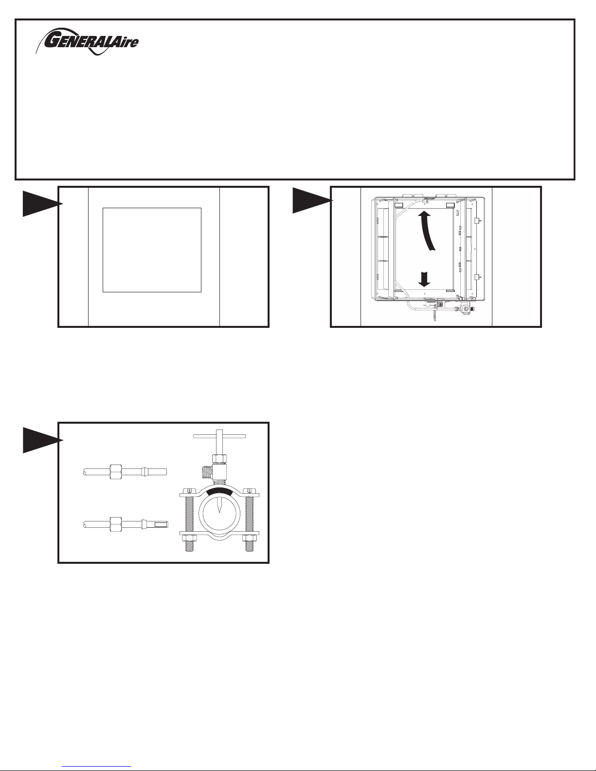
Mount the self tapping saddle valve on either a cold or a hot water pipe.
A side or top mount is best to avoid clogging from pipe sediment.
Connect 1/4” O.D. tubing to the saddle valve. Copper tubing requires a
brass compression nut and brass sleeve. Plastic tubing requires a brass
insert inside the tubing, a plastic sleeve on the outside with a brass
compression nut.
NOTE: DO NOT USE PLASTIC TUBING ON HOT WATER OR IN
CONTACT WITH ANY HOT PLENUM SURFACE OR DUCT.
INSTALLATION OF THIS SADDLE VALVE MUST MEET OR EXCEED
LOCAL CODES AND ORDINANCES.
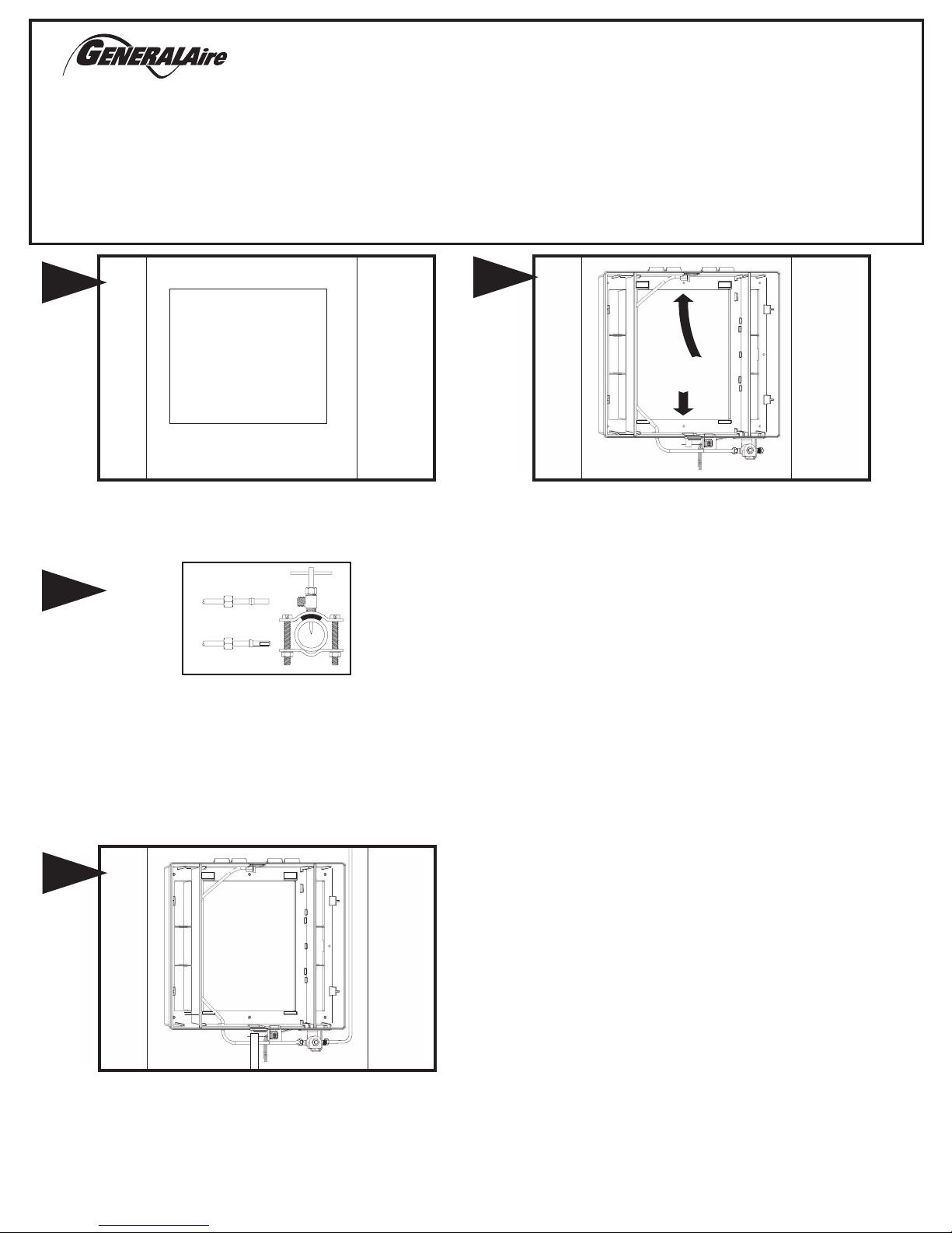
Select location on vertical surface of warm air plenum for mounting
humidifier. Tape mounting template in place making sure the template is
level. Do not install humidifier where the blanked off ends of a cooling coil
will restrict air flow to the humidifier. Cut out center section of template.
Open cover and remove evaporator pad assembly. Humidifier
chassis is self retaining, slide top side in first then slide chassis
down. Level chassis and install eight screws.
Fresh Indoor Air Quality
Connect 1/4" water supply tube to inlet of solenoid.
DO NOT USE
PLASTIC TUBING IN CONTACT WITH ANY HOT PLENUM
SURFACE OR DUCT. IF USING PLASTIC TUBING, USE TUBE
SUPPORT P189 AND PLASTIC COMPRESSION SLEEVE P190.
Connect drain hose to 1/2" spout on humidifier cabinet using hose clamp if
necessary. Run 1/2" hose to suitable drain such as floor drain, sewer or
laundry sink. Be sure hose has continuous slope and is not kinked at any point.
4
Page 2
24V OUTPUT FROM HUMIDIFIER (RED WIRES) OR
727-58 24 V. TRANSFORMER SWITCHED WITH FURNACE
OR 24 VAC POWER SUPPLY SWITCHED WITH FURNACE.
HUMIDIFIER CONTROL LEADS
(YELLOW WIRES)
OUTDOOR TEMP. SENSOR
(NOT USED IN MANUAL MODE)
AC L
AC N
HUM
SNSR
AC L
AC N
HUM
SNSR
Turn on water supply and plug in power cord to check operation of
humidifier. Set humidistat to a demand setting. With the furnace off, the
solenoid valve should be closed and the humidifier fan not running. Start
the furnace, the solenoid valve should open and the humidifier fan run
when the blower or burner circuit is energized. Check flow of water
through distributor trough and evaporator pad. The standard GA4231
yellow orifice will supply approximately 3.5 GPH of water at a line water
pressure of 60 psi. For low water pressures (20-40 psi) a larger orifice
GA4299 is available to provide the same flow. Leave humidistat set at the
recommended setting.
Replace evaporator pad assembly and humidifier cover. Insert low
voltage six connector wiring harness from cover into chassis solenoid
harness.
7
8
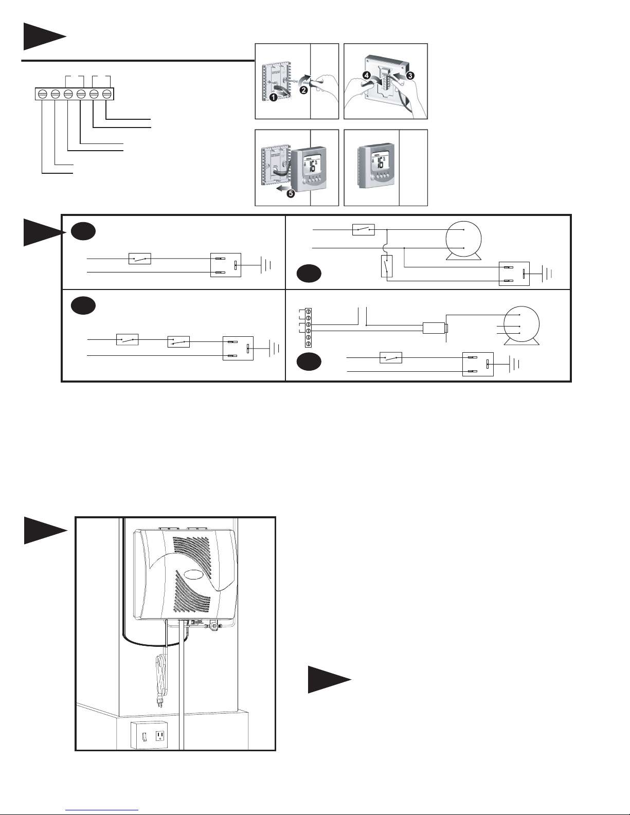
CIRCUIT DESCRIPTION
The humidifier is connected to the 120 volt AC circuit through a control
relay. The secondary coil of an isolation transformer, a diode and resistor
supply 24 volts DC for the control circuit which also includes the humidistat
and relay coil. When the control circuit is completed by the humidistat, the
relay closes, supplying 120 volts to the fan motor and 24 volts to the
solenoid valve.
L1
(HOT)
L2
115v.
60CY.
HUMIDIFIER CONTROL LEADS
(YELLOW WIRES)
FAN CONTROL
ON-OFF
SWITCH
SINGLE SPEED
BLOWER MOTOR
ACC
EAC
(HOT)
C
115v.
60CY.
ON-OFF
SWITCH
6A
6C
6B
INSTRUCTIONS FOR WIRING HUMIDIFIER
FIG. 6A WITH FURNACE CIRCUIT BOARD
On furnaces with output terminals ACC, or EAC check output
voltage to determine that terminals are 115V. Connect on-off
switch in series with the hot wire.
NOTE: ALL WIRING SHOULD COMPLY WITH LOCAL
ELECTRICAL CODES.
FIG. 6B WITH SINGLE SPEED BLOWER MOTOR
On furnaces with single speed blowers, mount a junction box and 115v.
grounded outlet connected in parallel with the blower circuit. Connect the
on-off switch in series with the hot or black wire.
FIG. 6C WITH TWO SPEED BLOWER MOTOR
On furnaces with a two speed blower, the humidifier and a Model 12500
Air Pressure Switch may be wired from a continuous 115 volt power
source. Install the on/off switch and Air Pressure Switch in series with the
hot or black wire. The Air Pressure Switch will detect furnace operation
and supply power to the humidifier accordingly.
FIG. 6D WITH TWO SPEED BLOWER MOTOR
On furnaces with a two speed blower, the humidifier may be wired from a
continuous 115 volt power source. Install the on/off switch in series with
the hot or black wire. Install the GA50 Current Sensing Relay in series
with the humidistat circuit. The Current Sensing Relay will detect furnace
operation and supply power to the humidifier accordingly.
GRD
HUMIDIFIER
120v. OUTLET
HUMIDIFIER
COMMON LEAD
120v. OUTLET
C
HI
LO
GA50 CURRENT
SENSING RELAY
MULTI
SPEED
BLOWER
MOTOR
6D
12500 AIR
PRESSURE
SWITCH
NO
C
L1
(HOT)
L2
115v.
60CY.
ON-OFF
SWITCH
GRD
HUMIDIFIER
120v. OUTLET
L1
(HOT)
L2
115v.
60CY.
ON-OFF
SWITCH
GRD
HUMIDIFIER
120v. OUTLET
GRD
6
5
1. Follow the installation instructions
supplied with the humidistat.
2. To remove the humidistat from the
base, squeeze the louvered base at
the top and bottom.
3. Before wall mounting, please
remove the gasket.
�
4. Before return air duct mounting,
please remove the breakout piece.
E2 HUMIDISTAT
8
Page 3
POUR L'INSTALLATION SUR UNE
SURFACE VERTICALE DU PLÉNUM À
AIR CHAUD DE N'IMPORTE QUELLE
CHAUDIÈRE À AIR PULSÉ
MATÉRIAUX ADDITIONNELS POUVANT ÊTRE REQUIS :
1. Tube d'alimentation en plastique de 1/4 po de diamètre ou tube d'alimentation
en cuivre de 1/4 po pour les applications pour eau chaude
2. Commutateur de pression d'air (G.F. modèle n° 12500 suggéré)
3. Boîte de connexion, prise de 115 V avec terre, couvercle et fil
4. Tuyau d'évacuation de 1/2 po de diam. int.
5. n° 8 x 3/4 po vis du montage
3
Monter le robinet-vanne à étrier autotaraudeur sur un tuyau d'eau
chaude ou d'eau froide. Un montage latéral ou sur le dessus est idéal
pour éviter un engorgement causé par les sédiments du tuyau.
Connecter un tuyau d'un diam. ext. de 6 mm (1/4 po) au robinet-vanne à
étrier. Les tuyaux en cuivre exigent un écrou à compression et un
manchon en laiton. Les tuyaux en plastique exigent un insert en laiton à
l'intérieur des tuyaux et un manchon en plastique à l'extérieur avec un
écrou à compression.
REMARQUE : NE PAS UTILISER DE TUYAUX EN PLASTIQUE AVEC
DE L'EAU CHAUDE OU SUR UNE SURFACE DE CONTACT CHAUDE
DE PLÉNUM OU DE CONDUIT. L'INSTALLATION DE CE
ROBINET-VANNE À ÉTRIER DOIT RESPECTER OU DÉPASSER LES
EXIGENCES DES CODES LOCAUX ET AUTRES ORDONNANCES.
Choisir un emplacement sur la surface verticale du plénum d'air chaud
avant de monter l'humidificateur. Mettre la matrice de montage en place
en s'assurant qu'elle soit à niveau. Ne pas installer l'humidificateur dans
un endroit ou les bouts bouchés d'un serpentin refroidisseur entraveront le
débit d'air vers l'humidificateur. Découper la partie centrale du gabarit.
Ouvrir le couvercle et retirer l’assemblage du patin d’évaporateur.
Le châssis de l’humidificateur est autonome; insérer la partie
supérieure en la glissant, puis faire glisser tout le châssis vers le
bas.
INSTALLATEUR : VEUILLEZ REMPLIR ET POSTER LA CARTE DE GARANTIE UNE FOIS L'INSTALLATION
TERMINÉE. LAISSER LES DIRECTIVES D'INSTALLATION AU PROPRIÉTAIRE DE LA MAISON.
1000 SÉRIES
HUMIDIFICATEUR PUISSANT
À CIRCULATION DIRECTE
PRÉCAUTION : L'installateur doit être un technicien qualifié et expérimenté. Couper l'alimentation électrique
avant de commencer l'installation. Ne pas installer l'appareil dans un endroit où la température peut descendre
sous 0 °C (32 °F) ou si la température du plénum dépasse 93 °C (200 °F). Pour maximiser la capacité
d'évaporation, installer l'humidificateur sur le plénum d'alimentation en air chaud. Lors d'un branchement à un
circuit de ventilateur à plusieurs vitesses, voir l'étape 6C & 6D.
INSTRUCTIONS D'INSTALLATION POUR LE ROBINET-VANNE À ÉTRIER
Tuyau en cuivre
1. Rétracter la tige à perforation dans le corps de la vanne en tournant la poignée dans
le sens horaire.
2. Visser le corps de la vanne dans le support supérieur et serrer.
3. Placer le joint d'étanchéité en caoutchouc par-dessus la tige de perforation.
4. Assembler le robinet-vanne à étrier par-dessus le tuyau en cuivre en utilisant les vis
écrous et supports inférieurs fournis.
5. Serrer les vis de façon égale et ferme. Les supports doivent être parallèles.
6. Terminer la connexion de compression vers la sortie du robinet-vanne à étrier.
7. Tourner la poignée dans le sens horaire pour percer le tuyau et fermer le
robinet-vanne à étrier.
8. Tourner la poignée dans le sens antihoraire pour ouvrir le robinet-vanne à étrier et le
laisser ouvert pendant quelques secondes pour évacuer la saleté du tuyau et de la
tuyauterie.
Tuyau en acier, en laiton ou en plastique dur.
1. Fermer l'alimentation en eau et vidanger le tuyau.
2. Tourner la poignée dans le sens horaire pour exposer la tige de perforation et fermer
le robinet-vanne à étrier.
3. Placer le joint d'étanchéité en caoutchouc par-dessus la tige de perforation.
4. Percer un trou de 3 mm (1/8 po) avec une perceuse à manivelle pour éviter les
risques de choc électrique.
5. Assembler le robinet-vanne à étrier par-dessus le tuyau en acier, laiton ou plastique
dur en utilisant les vis, écrous et supports inférieurs fournis.
6. Serrer les vis de façon égale et ferme. Les supports doivent être parallèles.
7. Terminer la connexion de compression vers la sortie du robinet-vanne à étrier.
8. Tourner la poignée dans le sens antihoraire pour ouvrir le robinet-vanne à étrier et le
laisser ouvert pendant quelques secondes pour évacuer la saleté du tuyau et de la
tuyauterie.
Raccords de tuyau filetés
1. Tourner la poignée dans le sens horaire pour exposer la tige de perforation et fermer
le robinet-vanne à étrier.
2. Sceller le filetage du corps de la vanne avec un scellant ou du ruban adhésif.
3. Installer la vanne dans un raccord NPT de 3 mm (1/8 po).
4. Terminer la connexion de compression vers la sortie du robinet-vanne à étrier.
5. Tourner la poignée dans le sens antihoraire pour ouvrir le robinet-vanne à étrier et le
laisser ouvert pendant quelques secondes pour évacuer la saleté du tuyau et de la
tuyauterie.
TUYAUX EN
CUIVRE
TUYAUX EN
PLASTIQUE
Fresh Indoor Air Quality
1
1
2
2
Page 4

DESCRIPTION DU CIRCUIT
L'humidificateur est connecté au circuit de 120 V ca par un relais de
commande. Le bobinage secondaire d'un transformateur d'isolement, une
diode et une résistance fournissent une tension de 24 volts cc pour le
circuit de commande qui comprend également l'humidistat et le bobinage
de relais. Une fois le circuit de commande complété par l’humidostat, le
relais se ferme et fournit 120 volts au moteur du ventilateur et 24 volts à
l'électrovalve.
Raccorder le tuyau d'alimentation d'eau de 1/4 po au filtre en
laiton de l'entrée du solénoïde. AUCUN TUYAU EN PLASTIQUE
NE DOIT ENTRER EN CONTACT AVEC DES CONDUITS OU
DES SURFACES DE PLÉNUM CHAUDS.
Si à l'aide de la
tuyauterie en plastique, employez l'appui de tube fourni, P189.
Raccorder le boyau de vidange au bec de 1/2 po sur
l'humidificateur à l'aide du collier de durite fourni.
Acheminer un
boyau d'un diam. int. de 1,27 cm (1/2 po) vers un drain adéquat,
comme un drain de sol, d'égout ou d'évier de lavage. S'assurer
que le boyau est en pente continue et n'est déformé en aucun
point.
4
PRESSOSTAT
D'AIR MODÉLE
12500
(ÉLECTRIFIER)
FILS CONDUCTEURS
JAUNES DE L’HUMIDISTAT
COMMANDE DE VENTILATEUR
BOUTON
VENTILATUR UNE
SEULE VITESSE
ACC
EAC
(ÉLECTRIFIER)
C
115v.
60CY.
BOUTON
6A
6C
INSTRUCTIONS FOR WIRING HUMIDIFIER
FIG. 6A AVEC CARTE DE CIRCUIT IMPRIMÉ
Sur les chaudières avec des bornes de sortie ACC (accessoire)
ou EAC (purificateur d’air électronique), vérifier la tension de
sortie pour s’assurer que les bornes sont à 115� V.
FIG. 6B AVEC MOTEUR DE VENTILATEUR À VITESSE
UNIQUE
Sur les chaudières avec ventilateurs à vitesse unique, installer
une boîte de jonction et une prise 115� V mise à la terre branchée
en parallèle avec le circuit du ventilateur. Raccorder
l’interrupteur Marche/Arrêt en série avec le fil sous tension ou
noir.
REMARQUE : TOUT LE CÂBLAGE DOIT RESPECTER LES
CODES ÉLECTRIQUES LOCAUX.
FIG. 6C AVEC MOTEUR DE VENTILATEUR À DEUX VITESSES
Sur les fournaises équipées d'un ventilateur à deux vitesses,
l'humidificateur et un pressostat d'air modèle 12500 peuvent être
raccordés à une source d'alimentation électrique continue de 115 volts.
Installer l’interrupteur Marche/Arrêt et le pressostat d’air en série avec le fil
sous tension ou noir. Le pressostat d'air détectera le fonctionnement de la
fournaise et fournira l'alimentation électrique nécessaire à l'humidificateur.
FIG. 6D AVEC MOTEUR DE VENTILATEUR À DEUX VITESSES
Sur les chaudières munies d’un ventilateur deux vitesses, l’humidificateur
peut être branché sur une source d’alimentation continue 115� volts.
Installer l’interrupteur Marche/Arrêt en série avec le fil sous tension ou
noir. Installer le relais ampèremétrique GA50 en série avec le circuit de
l’humidostat. Le relais ampèremétrique détectera le fonctionnement de la
chaufferette et fournira l’alimentation à l'humidificateur en conséquence.
TERRE
120v. PRISE
120v. PRISE
120v. PRISE
120v. PRISE
NEUTRON
MOTEUR
DE
VENTILATEUR
À VITESSES
MULTIPLES
NO
C
L1
(ÉLECTRIFIER)
L2
115v.
60CY.
BOUTON
TERRE
(ÉLECTRIFIER)
BOUTON
TERRE
TERRE
5
1. Suivre les instructions fournies aec
l’humidistat.
2. Pour enlever le humidistat de la base, serrez
la base à abats-sons au dessus et au bas.
3. Avant le placement sur le mur, enlevez svp
la garniture.
�
4. Avant le montage sur le conduit, enlevez svp
la pièce maîtresse.
E2 L'HUMIDISTAT
24V LA PRODUCTION DE L’HUMIDIFICATEUR (LES FILS ROUGES) OU
727-58 24 V. LE TRANSFORMATEUR ÉCHANGÉ
AVEC L’OPÉRATION DE
CHAUFFAGE OU 24 ALIMENTATION ÉLECTRIQUE VAC ÉCHANGÉ AVEC
L’OPÉRATION DE CHAUFFAGE.
FILS CONDUCTEURS
JAUNES DE L’HUMIDISTAT
DÉTECTEUR POUR L
A TEMPÉRATURE EXTÉRIEURE
(NON UTILISÉ DANS LE MODE MANUEL)
AC L
AC N
HUM
SNSR
AC L
AC N
HUM
SNSR
L1
L2
115v.
60CY.
6B
C
HI
LO
RELAIS
AMPÈREMÉTRIQUE
GA50
6D
L1
L2
115v.
60CY.
6
Page 5

PARTS LIST FOR HUMIDIFIER
900-9 NOZZLE
900-10 SPOUT
900-40 PAD RAIL
GA19 EVAPORATOR PAD
900-15 DISTRIBUTOR TROUGH
GA4247 FAN BLADE
900-14 DRAIN PAN
GA4237 MOTOR
900-16 NAMEPLATE
1000-11 HARNESS - BOARD
GA4238 RELAY ASS'Y
1137-31 POWER SUPPLY CORD
GA4231 ORIFICE - YELLOW
P-190 COMPRESSION SLEEVE (PLASTIC)
P-101 COMPRESSION NUT
GA4235 DISTRIBUTOR TUBE
P-189 TUBE SUPPORT
P-101 COMPRESSION NUT
P-102 COMPRESSION SLEEVE (BRASS) OR
P-190 COMPRESSION SLEEVE (PLASTIC)
GA4004 STRAINER SCREEN
GA4045 SOLENOID & HARNESS
ASSEMBLY
Fresh Indoor Air Quality
FILL OUT AND MAIL THIS
WARRANTY CARD AND
LITERATURE REQUEST FORM
A
IR CLEANERS AND AIR PURIFIERS
H
UMIDIFIERS
D
IGITAL HUMIDITY GAGE
A
IR FILTER GAGE
FORM NO. 1000-16 (FILE 15066) REV. A
F
UEL OIL FILTERS AND
A
CCESSORIES
Litho in U.S.A.
Page 6

The operating principle of the humidifier is based on the most efficient
and economical means of evaporating water to the air. The heat
necessary for evaporating water is produced by the furnace.
The water supply to the humidifier is controlled by the electric solenoid
valve. The solenoid valve and humidifier fan are controlled by a
humidistat connected through an isolation relay. The humidistat is
designed for wall mounting in the living area or surface mounting on the
return air duct. ELECTRICAL RATING: 24 VAC/ 60 Hz.
DO NOT SET RELATIVE HUMIDITY TOO HIGH DURING COLD
WEATHER. EXCESSIVE HUMIDITY MAY CAUSE CONDENSATION
ON WINDOWS OR IN WALLS. REFER TO RECOMMENDED
SETTINGS AS DESCRIBED IN THE HUMIDISTAT OWNERS
MANUAL.
Water flows through a strainer, is metered through an orifice to provide
the proper amount of water, and is supplied to the evaporator pad by
the distributor trough. Air from the warm air plenum is pulled through
the wetted evaporator pad by the humidifier fan and returned to the
warm air plenum to be circulated through the living area. Moisture is
evaporated to the air passing through the evaporator pad.
Minerals are not blown into the air stream as occurs in atomizing
humidifiers; they are left on the evaporator pad where a high
percentage is carried off with the waste water.
When the humidifier is installed and operating, no adjustments are
necessary other than setting the control knob on the humidistat to the
desired level of humidification.
To turn the humidifier off, close water supply valve, switch electrical
power off and turn humidistat off.
This humidifier, if properly registered by the return of the warranty registration card to the manufacturer, is warranted to the consumer against defects in
materials and workmanship for a period of ten years from the date of installation. Evaporator pads, water strainers or metering orifices are not covered by
this limited warranty or any other warranties. Any other defective parts will be repaired without charge except for removal, reinstallation and
transportation costs. To obtain repair service under this limited warranty, the consumer must send the defective part or the complete humidifier to the
manufacturer.
THERE ARE NO EXPRESS WARRANTIES COVERING THIS AIR CLEANER OTHER THAN AS SET FORTH ABOVE, THE IMPLIED WARRANTIES OF
MERCHANTABILITY AND FITNESS FOR A PARTICULAR PURPOSE ARE EXPRESSLY EXCLUDED. THE MANUFACTURER ASSUMES NO
LIABILITY IN CONNECTION WITH THE INSTALLATION OR USE OF THIS PRODUCT, EXCEPT AS STATED IN THIS LIMITED WARRANTY. THE
MANUFACTURER WILL IN NO EVENT BE LIABLE FOR INCIDENTAL OR CONSEQUENTIAL DAMAGES.
This limited warranty gives you specific legal rights, and you may also have other rights which vary from state to state. Some states do not allow either
limitations on implied warranties, or exclusions from incidental or consequential damages, so the above exclusion and limitation may not apply to you.
Any questions pertaining to this limited warranty should be addressed to the manufacturer. (U.S.A.: The manufacturer has elected not to make available
the informal dispute settlement mechanism which is specified in the Magnuson-Moss Warranty Act.)
GENERAL FILTERS, INC. CANADIAN GENERAL FILTERS, LTD.
NOVI, MICHIGAN 48375-1115 SCARBOROUGH, ONTARIO M1R3B7
WWW.GENERALAIRE.COM WWW.CGFPRODUCTS.COM
Your Humidifier is engineered to give helpful and trouble-free humidification. For maximum efficiency the following cleaning procedures should be carried
out at the end of each heating season:
1. Turn off water supply and electrical power to humidifier.
2. Remove cover, water distributor trough, evaporator pad, pad rails and drain pan. Clean excessive mineral
deposits from the distributor trough, drain pan, pad rails and humidifier cabinet. A solution of 1/2 vinegar & 1/2
water will help loosen mineral deposits.
Inspect drain hose, clean or replace as necessary.
3. If the evaporator pad has excessive mineral deposits, replace with a new “GA19” evaporator pad. Install
trough, pad rails and drain pan. Replace cover, reconnect electrical plug..
4. In heavy mineral areas or if the solenoid valve fails to function disconnect the 1/4” water supply line from the
solenoid valve. Carefully pull the strainer screen (P.N. 900-8) from the valve body (P.N. 900-6). Clean the
mineral deposits from all parts. If the orifice is clogged, it may be opened by inserting a small pin. Reinsert the
filter into the valve body.
5. Reconnect the 1/4” water line to the solenoid valve if necessary. Turn on the water supply and check all points
for leakage. The operation of the unit may be checked by starting the furnace. The humidifier operates only
when the furnace blower is running or the burner circuit is energized. The humidifier is now ready for operation.
6. During the summer, turn off water supply and electrical power to humidifier.
CARE AND MAINTENANCE
LIMITED WARRANTY
HOW THE HUMIDIFIER WORKS
AU PROPRIÉTAIRE� : INSCRIVEZ-VOUS EN LIGNE AU
WWW.GENERALAIRE.COM OU REMPLISSEZ LA CARTE
D’ENREGISTREMENT PUIS POSTEZ-LA À L’ADRESSE SUIVANTE� :
OWNER REGISTER ONLINE AT
WWW.GENERALAIRE.COM OR
FILL IN REGISTRATION AND MAIL TO:
O
WNER'S NAME
Nom du propriétaire:
MODEL 1000
MODÈLE 1000
WARRANTY REGISTRATION
Enregistrement de la garantie
S
TREET
A
DDRESS
Adresse:
D
EALER'S
N
AME
Nom du marchand:
D
ATE OF
I
NSTALLATION
D
ATE DE
I
NSTALLATION
C
ITY
Ville:
P
OSTAL
C
ODE
Code postal:
S
TATE
Province:
S
TREET
A
DDRESS
Adresse:
C
ITY
Ville:
P
OSTAL
C
ODE
Code postal:
S
TATE
Province:
S
ERIAL
N
UMBER
N
UMÉRO DE
S
ÉRIE
GENERAL FILTERS, INC.
43800 GRAND RIVER AVE
NOVI, MI 48375-1115
AT
OUTSIDE
TEMPERATURE
RECOMMENDED
SETTING
-20ϒF -29ϒC 15%
-10ϒF -23ϒC 20%
0ϒF -18ϒC 25%
+10ϒF -29ϒC
+20ϒF - 7ϒC
30%
35%
+30ϒF - 1ϒC 40%
Page 7

GA4237 MOTEUR DU
VENTILATEUR
900-16 PLAQUE
SIGNALÉTIQUE
900-9 BUSE
900-10 BEC
900-40 RAIL DE PATIN
GA19 BLOC ÉVAPORATEUR
900-15 GOULOTTE DU DISTRIBUTEUR
GA4247 PALE DE VENTILATEUR
GA4231 ORIFICE - JAUNE
P-102 MANCHON À COMPRESSION
P-101 ÉCROU À COMPRESSION
GA4235 TUYAU DU DISTRIBUTEUR
900-14 BAC DE RÉCUPÉRATION
1000-11 FAISCEAU - CARTE
GA4238 ENSEMBLE DE RELAIS
1137-31 CORDON D'ALIMENTATION
Remettre en place l’assemblage du patin d’évaporateur et le
couvercle de l’humidificateur. IInsérer le faisceau de câblage à six
connecteurs basse tension du couvercle dans le faisceau du
solénoïde.
7
Ouvrir l'eau et brancher le cordon d'alimentation pour vérifier le
fonctionnement de l'humidificateur. Régler l'humidistat en mode de
demande. Lorsque la chaudière n'est pas en marche, l'électrovanne
devrait être fermée et le ventilateur de l'humidificateur doit être immobile.
Démarrer la chaudière, l'électrovanne devrait être ouverte et le ventilateur
de l'humidificateur devrait être en marche lorsque le circuit de soufflerie
ou le brûleur sont alimentés en courant. Vérifier le débit d'eau passant
par la goulotte du distributeur et le bloc évaporateur. L'orifice standard
GA4231 fournira environ 3,5 gal/h d'eau à une pression de ligne d'eau de
60 psi. Pour des pressions d'eau basses (20 à 40 psi) un plus grand
orifice GA4299 est disponible pour fournir le même débit. Laisser
l'humidistat au réglage recommandé.
8
FORMULAIRE N° 1000-16 (DOSSIER 15066) REV. B
LISTE DES PIÈCES POUR L'HUMIDIFICATEUR
Lithographie aux É.-U.
P-189 TUBE SUPPORT
P-101 ÉCROU À COMPRESSION
P-102 MANCHON À COMPRESSION (LAITON) OU
P-190 MANCHON À COMPRESSION (PLASTIQUE)
GA4004 FILTRE À EAU
GA4045 VANNE ÉLECTROMAGNÉTIQUE
Page 8

Cet humidificateur, s'il est enregistré correctement en retournant la carte d'enregistrement de la garantie au fabriquant, est garanti au consommateur
contre tout défaut de matériaux et de main d'œuvre pour une période de dix ans à partir de la date d'installation. Garnitures de vaporisateur, écrans de
tamis de l'eau ou orifices régulateurs ne sont pas couverts par cette garantie limitée ou par toute autre garantie. Toute autre pièce défectueuse sera
réparée sans frais, hormis les coûts de désinstallation, de réinstallation et de transport. Pour obtenir un service de réparation avec cette garantie limitée,
le consommateur doit envoyer la pièce défectueuse ou l'humidificateur au complet au fabricant.
IL N'Y A AUCUNE GARANTIE EXPRESSE COUVRANT CE PURIFICATEUR D'AIR EN DEHORS DES DISPOSITIONS STIPULÉES CI-DESSUS, LES
GARANTIES TACITES QUANT À LA QUALITÉ MARCHANDE ET À L'APTITUDE À UN EMPLOI PARTICULIER SONT EXPRESSÉMENT EXCLUES. LE
FABRICANT NE PEUT ÊTRE TENU RESPONSABLE POUR L'INSTALLATION OU L'UTILISATION DE CE PRODUIT, SAUF DE LA MANIÈRE
INDIQUÉE DANS LA PRÉSENTE GARANTIE LIMITÉE. LE FABRICANT NE PEUT EN AUCUN CAS ÊTRE TENU RESPONSABLE POUR DES
DOMMAGES ACCESSOIRES OU INDIRECTS.
Cette garantie limitée vous donne des droits légaux spécifiques et vous pouvez jouir d'autres droits qui varient d'une juridiction à l'autre. Certaines
juridictions ne permettent pas de limites sur les garanties implicites ou d'exclusions pour les dommages accessoires ou indirects; les exclusions sus
mentionnées peuvent donc ne pas s'appliquer dans votre cas.
Toute question relative à cette garantie limitée doit être soumise au fabriquant. (É.-U. : Le fabricant à choisi de ne pas divulguer les termes de l'accord
spécifiés dans le " Magnuson-Moss Waranty Act ".)
GENERAL FILTERS, INC. CANADIAN GENERAL FILTERS, LTD.
NOVI, MICHIGAN 48375-1115 SCARBOROUGH, ONTARIO M1R3B7
WWW.GENERALAIRE.COM WWW.CGFPRODUCTS.COM
Votre humidificateur est conçu pour fournir une humidification d'appoint sans problèmes. Pour bénéficier d'un fonctionnement maximum, suivre les
étapes de nettoyage ci-dessous à la fin de chaque saison froide !
1. Fermer l'alimentation en eau et en électricité de l'humidificateur.
2. Retirer le tuyau de distribution d'eau, le bac du distributeur, le bloc évaporateur, le
rail de patin
et le bac de
récupération. Nettoyer les dépôts excessifs de minéraux dans le bac du distributeur, le couvercle, le bac de
récupération, le
rail de patin,
et le boîtier du distributeur. Une solution moitié vinaigre, moitié eau aide à déloger
les dépôts de minéraux.
3. Si le bloc évaporateur contient trop de dépôts de minéraux, le remplacer par un neuf " GA19 ".
Installer la
gouttière, les rails de coussinet et le bac de vidange. Remettre le couvercle.
4. Dans les endroits riches en minéraux ou si la vanne électromagnétique est défaillante, déconnecter la ligne
d'alimentation en eau de 6 mm (1/4 po) de la vanne électromagnétique. Retirer soigneusement le filtre à tamis
(P.N. 900-8) du raccord de l'orifice (P.N.900-6). Nettoyer les dépôts de minéraux de toutes les pièces. Si
l'orifice est bloqué, on peut l'ouvrir en y insérant une petite aiguille. Réinsérer le filtre dans l'électrovanne.
5. Raccorder la conduite d'eau de 6 mm (1/4 po) à la vanne électromagnétique au besoin. Ouvrir l'alimentation
en eau et vérifier tous les points de fuite. Le fonctionnement de l'appareil peut être vérifié en démarrant la
fournaise. L'humidificateur fonctionne uniquement lorsque le ventilateur de la fournaise est en marche ou que
le circuit du brûleur est activé. L'humidificateur est maintenant prêt à fonctionner.
6. Pendant la période d'été, fermer l'alimentation en eau et en électricité de l'humidificateur. Fermer
l'amortisseur à air.
SOINS ET ENTRETIEN
FONCTIONNEMENT DE L'HUMIDIFICATEUR
GARANTIE LIMITÉE
Le principe de fonctionnement de l'humidificateur est basé sur la façon la plus efficace et la plus économique d'évaporer l'eau dans l'air. La chaleur
nécessaire pour l'évaporation de l'eau est produite par la fournaise.
L'alimentation en eau vers l'humidificateur est contrôlée par la vanne électromagnétique. L’électrovalve et le ventilateur de l’humidificateur sont
commandés par un humidostat branché via un relais d’isolation. Cet hygrostat est conçu pour un montage mural dans l’aire de séjour ou un montage
en surface sur la gaine de reprise. CARACTÉRISTIQUES ÉLECTRIQUES : 24 V c.a. / 60 Hz.
NE PAS RÉGLER L'HUMIDITÉ RELATIVE TROP HAUT PENDANT LA PÉRIODE HIVERNALE. TROP D'HUMIDITÉ PEUT ENTRAÎNER DE LA
CONDENSATION SUR LES VITRES OU SUR LES MURS. CONSULTER LES RÉGLAGES RECOMMANDÉS, INDIQUÉS DANS LE MANUEL DU
PROPRIÉTAIRE DE L’HYGROSTAT.
L'eau s'écoule par une crépine, est mesurée par un orifice pour fournir la quantité adéquate et alimente le bloc évaporateur par la goulotte du
distributeur. L'air du plénum à air chaud est aspiré à travers le bloc évaporateur humecté par le ventilateur de l'humidificateur et retourné au plénum à
air chaud pour être circulé dans l'espace habité. L'humidité est évaporée dans l'air en passant par le bloc évaporateur.
Les minéraux ne sont pas soufflés dans le courant d'air, comme c'est le cas avec les humidificateurs à pulvérisation; ils restent sur le bloc évaporateur
où un fort pourcentage est évacué avec les eaux usées.
Lorsque l'humidificateur est installé et fonctionne, aucun réglage n'est nécessaire sauf le réglage du niveau voulu d'humidification par le bouton de
commande sur l'humidistat.
Pour éteindre l'humidificateur, fermer la vanne d'alimentation en eau, mettre hors tension et fermer l'humidistat.
-20ϒF -29ϒC 15%
-10ϒF -23ϒC 20%
0ϒF -18ϒC 25%
+10ϒF -29ϒC
+20ϒF - 7ϒC
30%
35%
+30ϒF - 1ϒC 40%
À LA
TEMPÉRATURE
EXTÉRIEURE
RÉGLAGE
RECOMMANDÉ
 Loading...