

GeneralAire 1000, 1000A, 1000M Installation & Owner's Manual
Installation & Owners Manual
Model 1000 (A & M)
Humidifier
GFI #5730 & 5735
• Installationbyanyoneotherthanaqualiedcontractorvoidsthewarranty.
• Productdesignedforresidentialinstallationonly.Commercialinstallationvoidswarranty.
• Modicationoralterationofproduct,parts,installationinstructionsorlocalsafetycodesvoidswarranty.
• Readourfullwarrantypolicyattheendofthisdocument.
Breathe Healthier
Please Read And Save These Instructions
Canadian General Filters, Ltd.
400 Midwest Rd.
Toronto, ON M1P3A9 Canada
Toll Free: (888) 216-9184
www.cgfproducts.com
General Filters, Inc.
43800 Grand River Avenue
Novi, Michigan 48375
Toll Free: (866) 476-5101
www.generalaire.com

2
Model 1000 Humidier Installation Manual
Breathe Healthier! Residential Whole-House Indoor Air Quality
Table of Contents
Specications 3
Unit Location 3
Additional Materials That May Be Necessary: 3
Installation 4-5
Installing The Control 5-6
Final Steps Of Installation 7
How The Humidier Works 7
Maintenance 8
Parts Drawing 8
Humidier Chassis Cut Out 9
Inside Your Box 9
Trouble Shooting 10
FAQ’s 10-11
Limited Warranty 12
Model 1000 Table of Contents
WARNING!
This symbol indicates: IMPORTANT INSTRUCTIONS!
Failure to heed them can result in serious injury or death.
CAUTION!
This symbol indicates: IMPORTANT INSTRUCTIONS!
Failure to heed them can result in serious injury or material property damage.
!
!
3
www.generallters.com
Model 1000 Humidier Installation Manual
Unit Location
• For installation on a vertical surface of the warm air plenum of any forced air furnace.
• WARNING: Disconnect electrical power before beginning installation.
• Do not install where temperatures fall below 32°F / 0° C or where plenum temperatures exceed 200° F / 93° C.
For maximum evaporative capacity, install this humidier on the warm air supply plenum.
Additional Materials That May Be Necessary:
1. 1/4" Diameter plastic supply tubing for cold water applications, or 1/4" copper supply tubing for hot water applications
2. Current sensing relay (Model #GA50 - GFI #7026) / or single pole single throw isolation relay
3. Junction box, 115V grounding outlet, cover and wire
4. 1/2” I.D. Drain hose / 3/4" PVC drain
5. #8 Self-piercing sheet metal screws
6. Misc. wire and connectors
Specifications
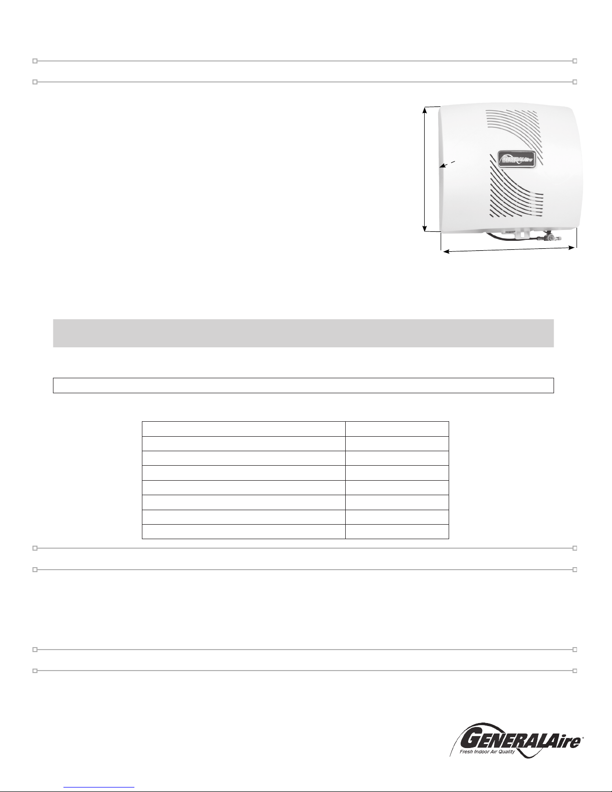
• Model: 1000 (A & M) Elite Flow Through Humidiers (GFI #5730 & #5735)
• Type: Fan Powered Flow Through
• GPD: 18 Based on 120° F / 49° C Plenum Temperature
• Warranty (Years): 10
• Replacement Vapor Pad®: GA19 (GFI#7919) (Replace 1-2 times per season)
• Dimensions (Inches): 16 W x 16-1/2 H x 10-1/2 D
• Weight (Pounds): 15
• Home Size (Sq. Ft.): To 3,000
• Installation: Warm Air / Return Air Plenum
• Plenum Opening (Inches): 14-1/8 W X 12 H
• Pallet Qty: 24
• Cabinet Construction: UV-Stable Automotive Grade Plastic
• Humidistat (Included): “M” Models: MHX3C / “A” Models: GFX3
• Voltage: 120VAC
• In The Box: “M” Models: MHX3C / “A” Models: GFX3 (Incuded) Humidier,
Humidistat, Control Bypass Damper, 24V Transformer, Solenoid Valve, Vapor Pad®, Saddle Valve, (GCV3412 Code Valve A Models), Installation Instructions, Template, Parts.
!
16” W
16-1/2” H
10-1/2” D
Expected Humidity Performance Coverage in Square Feet Based on Construction Type
Model No. GPD
Loose
(0.75 AC/H)
Average
(0.50 AC/H)
Tight
(0.30 AC/H)
Elite 570 12 800 Sq. Ft. 1200 Sq. Ft. 2000 Sq. Ft.
Elite 900 17 1115 Sq. Ft. 1650 Sq. Ft. 2800 Sq. Ft.
Elite 1000 18 1175 Sq. Ft. 1770 Sq. Ft. 3000 Sq. Ft.
Outside Design Temperature 0° F / -18° C
Outside Design R.H. 70% R.H.
Inside Design Temperature 70° F / 21° C
Inside Design R.H. 30% R.H.
Air Changes/hour (AC/H) 0.30
Ceiling Height (Feet) 8
Furnace Plenum Temperature 120° F / 49° C
Furnace Run Time For Calculating Sq. Ft. 8 Hour /1 Day
Humidifier Performance Baseline Criteria
4
Model 1000 Humidier Installation Manual
Breathe Healthier! Residential Whole-House Indoor Air Quality
Installation
1. Select a location on the vertical surface of warm air plenum
of a forced air handling system for mounting humidier that
allows for service and maintenance. Do not install humidier
where the blanked off ends of a cooling coil will restrict air
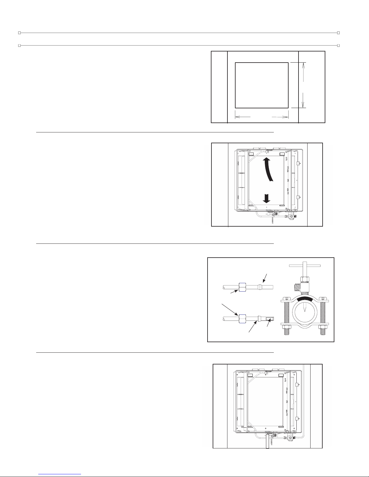
ow to the humidier. Cut out a square section 12-1/8” tall
by 14-1/8” wide as shown.
2. Open the cover and remove the evaporator pad assembly.
The humidier chassis is self retaining. Slide the top side
in rst, then slide the chassis down. Level the chassis and
install the eight screws (included).
3. Mount the self tapping saddle valve on either a cold or a hot
water pipe. A side or top mount is best to avoid clogging
from pipe sediment. Connect 1/4” O.D. tubing to the saddle
valve. Copper tubing requires a brass compression nut and
brass sleeve. Plastic tubing requires a brass insert inside the
tubing in addition to a plastic ferrule and brass nut.
CAUTION: do not use plastic tubing on hot water or in
contact with any hot plenum surface or duct. Installation
of this saddle valve must meet or exceed local codes and
ordinances.
4. Connect 1/4" water supply tube to inlet of solenoid.
Connect drain hose to 1/2" spout on humidier cabinet using
hose clamp if necessary. Run 1/2" hose to suitable drain
such as oor drain, sewer or laundry sink. Be sure hose has
continuous slope and is not kinked at any point.
!
1
2
4
12-1/8”
14-1/8”
COPPER
TUBING
PLASTIC
TUBING
Plastic
Sleeve
Brass
Insert
Brass
Sleeve
Compression
Nut
5
www.generallters.com
Model 1000 Humidier Installation Manual
5. GCV3412 Code Valve Installation Instructions*
Copper Pipe:
1. CAUTION: Turn off water supply.
2. Clean pipe, ttings and valve with sandpaper or wire brush.
3. Apply a thin layer of ux to all surfaces to be soldered.
4. Assemble valve to pipe and/or ttings.
5. Cooling the valve by wrapping a wetted rag around the valve is optional.
6. WARNING: For your safety, this should be performed by a
licensed contractor only. Heat the joints with a torch. Apply solder to
each joint. Continue to apply heat sufcient to keep solder liquid.
7. After solder has lled entire joint area, remove heat and allow joint to cool. Do
not move or disturb.
8. Slide compression nut over 1/4” copper tube followed by compression sleeve.
9. Insert tube into valve fully and tighten nut.
10. Turn on water supply and check for leaks.
*Code Valve Is Included With Automatic Models Only
Installation Cont.
!
!
1/2” TEE
3/4” TEE
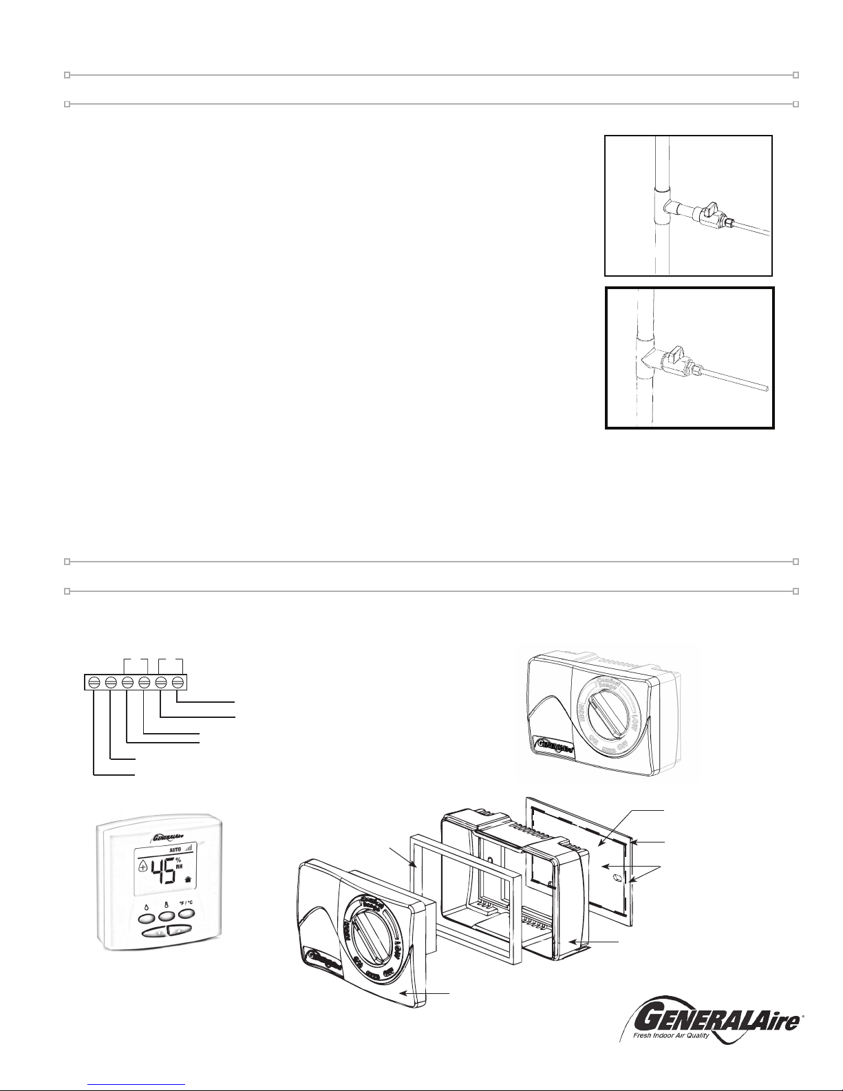
Installing The Control
GFX3 (Automatic Models) MHX3C (Manual Models)
24V OUTPUT FROM HUMIDIFIER (RED WIRES) OR
727-58 24 V. TRANSFORMER WITH CONSTANT POWER
OR 24 VAC POWER SUPPLY WITH CONSTANT POWER
HUMIDIFIER CONTROL LEADS
(YELLOW WIRES)
OUTDOOR TEMP. SENSOR
(NOT USED IN MANUAL MODE)
AC L
AC N
HUM
SNSR
Thin Gasket
Face
FIG. 1
WALL MOUNT: Use
Outer & Inner Portions
DUCT MOUNT: Use
ONLY Outer Portion
Mounting
Base
Thick Gasket
DUCT MOUNT ONLY
 Loading...