

Page 1
WIRELESS WATER ALARM
USER’ S MANUAL
Please resd this manual carefully and thoroughly before using this product
WA700
Page 2

TABLE OF CONTENTS
Introduction
Key Features
Safety Instruction
What’s in the Package
Product Overview
Setup Instructions
Setting the Zone on the Sensor-Transmitter
Installing the Remote Transmitter
Setting up the Remote Receiver
Testing
Operating Instructions
3
3- 4
4
4
5- 6
7- 10
7
8
9
10
10-11
Deploy the Unit
Dual Alarms
Specifications
Maintenance Instructions
Changing the Battery
Warranty Information
Return for Repair Policy
10
11
12
13
13
14
15
2
Page 3

INTRODUCTION
Thank you for purchasing General Tools & Instruments’ WA700
Wireless Water Alarm. Please read this user’s manual carefully
and thoroughly before using the instrument.
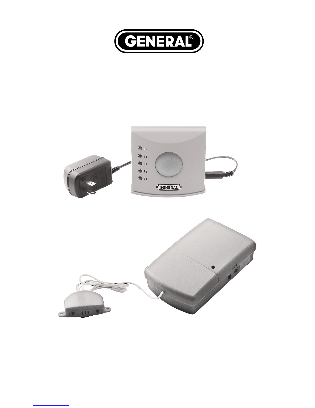
The WA700 is a low-cost, two part water alarm system. It consists
of a sensor-transmitter that is to be located in areas of high water
usage, and a receiver which should be placed in a commonly used
area in the house. It is ideal for detecting leaks from water heaters,
washing machines, plumbing and HVAC/R systems.
KEY FEATURES
Sounds alarm at sensor-transmitter and receiver when
water is detected
120-foot maximum wireless range typically enables
placement of sensor-transmitter in basement and
receiver in upstairs bedroom
Receiver can sound and display alarms from up to four
sensor-transmitters deployed in different zones. Units
can be paired on any of six channels to avoid interference
Standard package includes one receiver with AC adaptor
and one sensor-transmitter with “9V” battery. An optional
package of one additional sensor-transmitter and "9V'
battery (WA700SEN) is available
3
Page 4

Sensor with suction cup is at the end of 23-in. long
cord, increasing placement options. Transmitter unit
includes battery test button/LED on side
Long battery life (up to one year)
One-year limited warranty
SAFETY INSTRUCTION
Do not use the WA700 in the presence of flammable or
explosive gases.
WHAT’S IN THE PACKAGE
The WA700 comes in a blister pack containing
Receiver with 120VAC Adaptor
Sensor-transmitter with battery
Installation hardware: 1 hook, 2 plastic wall plugs, 4 screws
A hard copy of this user’s manual (inside the fold-over
card)
4
Page 5
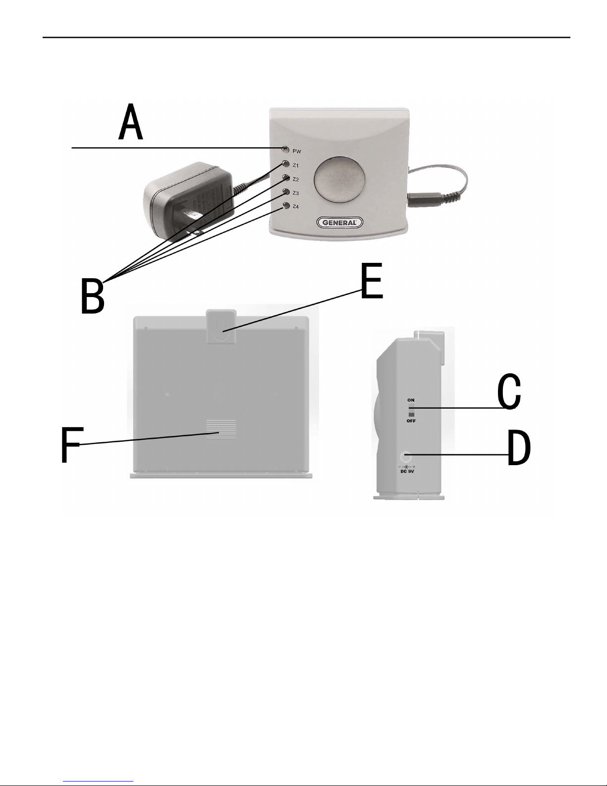
PRODUCT OVERVIEW
Fig 1 Receiver
A: Power indicator B: Zone indicators
C: On/Off switch D: DC 9V input
E: Mounting hole F: Speaker
5
Page 6

Fig 2 Sensor-transmitter
A: Low Battery indicator B: DC 9V input
C: Low Battery Test button D: Mounting hole
E: Zone Setting F: Channel Setting
G: Battery cover H: Sensor
6
Page 7

SETUP INSTRUCTIONS
SETTING THE ZONE ON THE SENSOR-TRANSMITTER
The following chart indicates the 4-zone setting parameters and
the picture shows a setting of Zone 1 (Z1).
Zone Setting
Z1 Z2 Z3 Z4
A 1 0 1 0
B 0 0 1 1
Note: The transmitter comes factory preset for Zone 1 (Z1)
7
Page 8

INSTALLING THE REMOTE TRANSMITTER
Remove the battery compartment cover on the back of the
transmitter.
Connect a fresh 9V battery (PP3 or equivalent) and place the
cover back on.
To check the battery condition, press the “TEST/LOW BATT.”
button located on right size of the transmitter. The red
LED indicator on the front of the transmitter will light up to
indicate an adequately charged battery. If the LED does not
light, install a fresh battery immediately.
Mount the transmitter in an appropriate location. The
transmitter is now ready to arm.
8
Page 9

SETTING UP THE REMOTE RECEIVER
Place the receiver in a convenient location, no further than
120 feet from the transmitter. Please note that walls,
metallic objects, etc. may reduce the range.
Plug the 120VAC Adaptor into the receiver.
Set the ON/OFF switch to the ON position and the green LED
indicator will light up. The receiver is now armed and ready.
9
Page 10

TESTING
The Remote Alarm System should be tested after installation.
Test for the water sensor: Place the tips of the water sensor in
water and observe the receiver. If the zone indicator lights up
and the transmitter "chirps", the sensor-transmitter is operating
properly.
Test for RF signal: Press the “TEST/LOW BATT.” button for 5
seconds to emit the RF signal. If the zone light on the receiver
lights and the alarm on the receiver sounds, the system is
operating properly.
The zone light will change to flashing if another zone has been
triggered.
OPERATING INSTRUCTIONS
DEPLOY THE UNIT
The receiver should be placed in a convenient location that is commonly
occupied. This will allow for quick reaction times in case of an
emergency. Each of the sensors should be placed in close proximity
to areas of high water usage (i.e. Hot Water Heater, Washing Machine,
Sinks, etc.) and can be mounted with a suction cup on the bottom. Doing
so will offer the most accurate readings and fast alert times in the event
10
Page 11

of a water buildup. The transmitter should be mounted at least 5 in.
or higher above the ground to keep it out of the way of a rising water
level.
DUAL ALARMS
The receiver will activate when water reaches both of the copper
contacts located in the transmitter, making it "chirp". The receiver
will emit a continuous, loud beeping sound until it is turned off by the
user. To reset the unit and shut off the sound, move the power switch
on the receiver to OFF and then to ON. The system will not arm again
until this process is completed.
11
Page 12

SPECIFICATIONS
Wireless Range 120 ft. (37m)
max (with no obstructions)
Operating Frequency 433.92 MHz
Alarm Volume 88dBA at Receiver
Receiver Zone Alarm Indicators LEDs
Sensor Dimensions 1.57 x 1.18 x 0.55 in.
(40 x 30 x 14mm)
Transmitter Dimensions 2.76 x 2.36 x 1.14 in.
(70 x 60 x 29mm)
Receiver Dimensions 3.70 x 3.31 x 1.46 in.
(94 x 84 x 37mm)
Length of Sensor Cord 23 in. (584mm)
Weight of Standard Package 6.0 oz. (170g)
Weight of Optional Package of One 3.2 oz. (91g)
Additional Sensor and "9V" Battery
(WA700SEN)
Power Source 9V AC adaptor for receiver
“9V” battery for sensor transmitter
Battery Life (typical) in 1 year
Standby Mode
12
Page 13

MAINTENANCE TIPS
CHANGING THE BATTERY
Plug the included “9V” battery into the wired socket inside the
compartment. The terminals of the battery and the socket mate
in only one way, with the smaller male terminal plugging into the
larger female terminal.
CHANGING THE CHANNEL
In case of signal interference, or if there are multiple receivers
present, you are able to change the channel setting. Using
tweezers, move the jumpers to either connect or disconnect the 6
pin sets on the back of each unit. Be sure that all the transmitters
are set up in the same pattern as the receiver they go to.
13
Page 14

WARRANTY INFORMATION
In the U.S, General warrants its instruments and accessories against
defects in material or workmanship for one year from the date of
purchase. General will replace or repair the defective unit, at its option,
subject to verification of the defect.
This warranty does not apply to defects resulting from abuse, neglect,
accident, unauthorized repair, alteration, or unreasonable use of the
product.
Any implied warranties arising from the sale of a General product,
including but not limited to implied warranties of merchantability
and fitness for a particular purpose, are limited to the above. General
shall not be liable for loss of use of the product or other incidental or
consequential damages, expenses, or economic loss, or for any claim
of such damage, expenses, or economic loss.
State laws vary. The above limitations or exclusions may not apply to
you.
We encourage you to register your product online. General will
extend your warranty an additional 60 days if you register at www.
generaltools.com/ProductRegistry.
14
Page 15

RETURN FOR REPAIR POLICY
Every effort has been made to provide you with a reliable
product of superior quality. However, in the event your instrument
requires repair, please contact our Customer Service to obtain an
RGA (Return Goods Authorization) number before forwarding the
unit via prepaid freight to the attention of our Service Center at
this address:
General Tools & Instruments
80 White Street
New York, NY 10013
212-431-6100
Remember to include a copy of your proof of purchase, your
return address, and your phone number and/or e-mail address.
15
Page 16

GENERAL TOOLS & INSTRUMENTS
TOLL FREE (800) 697-8665
e-mail: sales@generaltools.com
Specifications subject to change without notice
©2014 GENERAL TOOLS & INSTRUMENTS
NOTICE - WE ARE NOT RESPONSIBLE FOR TYPOGRAPHICAL ERRORS.
80 White Street
New York, NY 10013-3567
PHONE (212) 431-6100
FAX (212) 431-6499
www.generaltools.com
WA700 User’s Manual
MAN# WA700
05/30/14
 Loading...