

Page 1
LASER DISTANCE MEASURER
USER’S MANUAL
TS01
99 Washington Street
Melrose, MA 02176
Phone 781-665-1400
Toll Free 1-800-517-8431
Visit us at www.TestEquipmentDepot.com
Please read this manual carefully and thoroughly before using this product.
Page 2

TABLE OF CONTENTS
Introduction . . . . . . . . . . . . . . . . . . . . . . . . . . . . . . . . . . . . . . . . . . . . . 3
Key Features . . . . . . . . . . . . . . . . . . . . . . . . . . . . . . . . . . . . . . . . . . 3 –4
What’s in the Box . . . . . . . . . . . . . . . . . . . . . . . . . . . . . . . . . . . . . . . . . 4
Product Overview . . . . . . . . . . . . . . . . . . . . . . . . . . . . . . . . . . . . . . 4 –7
Safety Instructions . . . . . . . . . . . . . . . . . . . . . . . . . . . . . . . . . . . . . . . . 7
Setup Instructions . . . . . . . . . . . . . . . . . . . . . . . . . . . . . . . . . . . . . . . . 8
Install Batteries . . . . . . . . . . . . . . . . . . . . . . . . . . . . . . . . . . . . . . . . 8
Operating Instructions . . . . . . . . . . . . . . . . . . . . . . . . . . . . . . . . . 8 – 18
Powering On and Off . . . . . . . . . . . . . . . . . . . . . . . . . . . . . . . . . . . . 8
Quick Start Instructions . . . . . . . . . . . . . . . . . . . . . . . . . . . . . . . 8 –9
Choosing a Measurement Reference . . . . . . . . . . . . . . . . . . . . . . . 9
Clearing Values/Undoing Actions . . . . . . . . . . . . . . . . . . . . . . . . . . 9
Changing the Measurement Unit . . . . . . . . . . . . . . . . . . . . . . . . . . 10
Turning the Backlight On and Off . . . . . . . . . . . . . . . . . . . . . . . . . 10
Measuring Distances . . . . . . . . . . . . . . . . . . . . . . . . . . . . . . . 10 – 16
Direct Measurements . . . . . . . . . . . . . . . . . . . . . . . . . 10 – 11
Continuous Distance Measurement
(Distance Tracking) . . . . . . . . . . . . . . . . . . . . . . . . . 11 – 12
Adding and Subtracting Distances . . . . . . . . . . . . . . . 12 – 13
Indirect Measurements of Height
and Length using Triangulation . . . . . . . . . . . . . . . 13 – 16
Measuring Areas and Perimeters . . . . . . . . . . . . . . . . . . . . . . . . . 16
Measuring Volumes . . . . . . . . . . . . . . . . . . . . . . . . . . . . . . . . . . . . 17
Recalling Stored Measurements/Calculations . . . . . . . . . . . 17 – 18
Using the Laser Distance Measurer with the ToolSmart™ App
and an Apple iOS or Android Smartphone . . . . . . . . . . . . . . . . . . . 18
Specifications . . . . . . . . . . . . . . . . . . . . . . . . . . . . . . . . . . . . . . . . . . . 19
Operating & Maintenance Tips . . . . . . . . . . . . . . . . . . . . . . . . . . . . . 20
Warranty Information . . . . . . . . . . . . . . . . . . . . . . . . . . . . . . . . . . . . . 21
Return for Repair Policy . . . . . . . . . . . . . . . . . . . . . . . . . . . . . . . . . . . 22
FCC Statement . . . . . . . . . . . . . . . . . . . . . . . . . . . . . . . . . . . . . . . . . . 23
Manual del Usuario (en Español) . . . . . . . . . . . . . . . . . . . . . . . . 25 – 48
2
Page 3

INTRODUCTION
Thank you for purchasing General Tools & Instruments’ (General’s) TS01 ToolSmart
Laser Distance Measurer. Please read this user’s manual carefully and thoroughly
before using the instrument.
The Laser Distance Measurer (LDM) is designed to replace a tape measure for
professionals such as builders, architects, engineers, surveyors, carpenters,
plumbers, painters, electricians, realtors, home inspectors, HVAC system designers
and installers, and carpet/flooring installers and salesmen. The LDM works the
®
same whether used alone or in concert with an iOS
or Android™smartphone: it
projects a red laser beam onto a target and measures how long it takes the
reflected beam to return to the LDM. This time is proportional to the distance to the
target. The LDM’s range of 100 ft. (30m) makes it suitable for most indoor
measuring tasks and many outdoor jobs as well.
®
When used in concert with an iPhone
®
transmit—via Bluetooth
— to the mobile device all measurements and groups of
or Android™smartphone, the LDM can
measurements and calculations it makes. The phone initiates the data transfer
®
using a free app downloaded from the iTunes
App Store or Google Play Store.
Measured lengths, areas, perimeters and volumes can then be overlaid on photos
that the user can take using the app and the phone’s camera.
™
KEY FEATURES
• 100 ft. (30m) range
• Accuracy of ±1/16 in. (±1.5mm)
• Displays distances in feet with decimal fraction (default), feet + fractional inches,
inches or meters
• Calculates areas, perimeters and volumes
• Uses triangulation to calculate height or length from a distance
• Backlit 4-line LCD
• Continuous on-screen digital readout of LDM's angle with respect to the
horizontal in most measurement modes
iPhone®and iTunes®are trademarks of Apple Inc., registered in the U.S. and other countries.
™
is a trademark of Google Inc.
Android
The Bluetooth
General Tools & Instruments is under license.
®
word mark and logos are registered trademarks owned by Bluetooth SIG, Inc. and any use of such marks by
3
Page 4

• Addition, subtraction, and continuous measurement (tracking) modes ideal for
layout work
• Fast response time
• Automatically stores 20 most recent measurements/calculations
• References measurements from top or bottom of housing or end of extension
ruler
• Auto power off, auto laser off and auto backlight off
• Splashproof and dustproof to IP54 standard
• Pocket-sized and lightweight
• Powered by two “AAA” Alkaline batteries (included)
WHAT’S IN THE BOX
The LDM comes in a display box along with:
• A holster (soft pouch with a belt loop)
• Two “AAA” Alkaline batteries
• A small flat-head screwdriver for opening the battery compartment
• This user’s manual
PRODUCT OVERVIEW
Fig. 1 shows all of the controls on the LDM’s front panel. Fig. 2 shows all possible
display icons and indications. Familiarize yourself with the positions and functions
of these controls and indicators before moving on to the safety, setup and operating
instructions.
Fig. 1. The LDM’s front-panel controls
1.
Five-function button
measurement modes: Area, volume, two-point triangulation, three-point
triangulation, automatic height
Enters Continuous Distance Measurement (tracking) mode
2.
of Max and Min values
3.
Adds/subtracts next measurement to/from previous one
Recall mode, increments/decrements Record counter
4
. Press briefly to cycle through the five available
. In Memory
, with display
Page 5

1
MEASURE
ON
CLEAR
OFF
▲
▼
3
2
4
5
7
Fig. 1
4.
Measurement button
5.
Two-function button
reference options: top and bottom of LDM housing, and bottom of extension ruler.
Press and hold to cycle through four available distance units.
Enters Memory Recall mode
6.
7.
Two-function button
last action or clear (reset to zero) the last measurement or calculation
8.
Activates/deactivates Bluetooth transmission
calculations
. Activates laser and makes measurement
. Press briefly to cycle through three measurement
. Press and hold to power LDM off. Press briefly to undo
of measurements and
6
8
5
Page 6

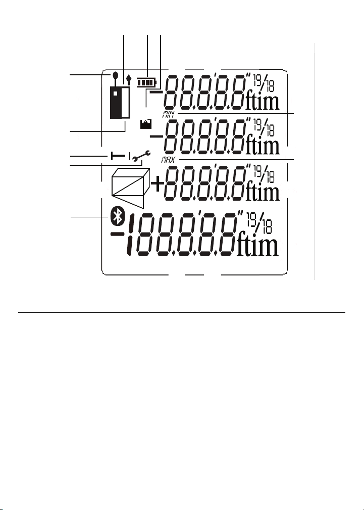
Fig. 2. The LDM’s display indications and icons
1. Measurements referenced from top of LDM housing
2. Flashes when laser is on
3. Measurements referenced from bottom of LDM housing or bottom of
extension ruler
4. Operating in Direct or Continuous Measurement Mode
5. Operating error indication
6–10. Measurement type indicator
Distance (direct)
Distance (indirect—triangulation with two inputs)
Distance (indirect—triangulation with three inputs)
Area and perimeter
Volume
11. Battery charge indicator
12. No. of stored record displayed
13. Top display line
14. Value displayed on second line is a minimum
15. Second display line
16. Value displayed on third line is a maximum
17. Third display line
18. Bottom (summary) display line (shows last measurement or calculation
result)
19. Bluetooth transmission enabled icon
6
Page 7
{
{
{
{
{
2
3
4
5
1 11 12
6,7,8,9,10
13
14
15
16
17
18
8
8
➤
11 12
1
2
13
14
3
4
5
6,7,8,9,10
19
Fig. 2
SAFETY INSTRUCTIONS
The LDM’s targeting laser is a Class 2 type that emits less than 1 mW of radiation
at a wavelength between 630 and 660 nanometers.
Avoid direct eye contact with the laser, and do not point it at people or animals. Eye
protection is normally afforded by the blink reflex. U.S. law prohibits pointing a laser
beam at aircraft; doing so is punishable by a fine of up to $10,000 and
imprisonment.
CAUTION!
15
16
17
18
7
Page 8
SETUP INSTRUCTIONS
MEASURE
ON
CLEAR
OFF
MEASURE
ON
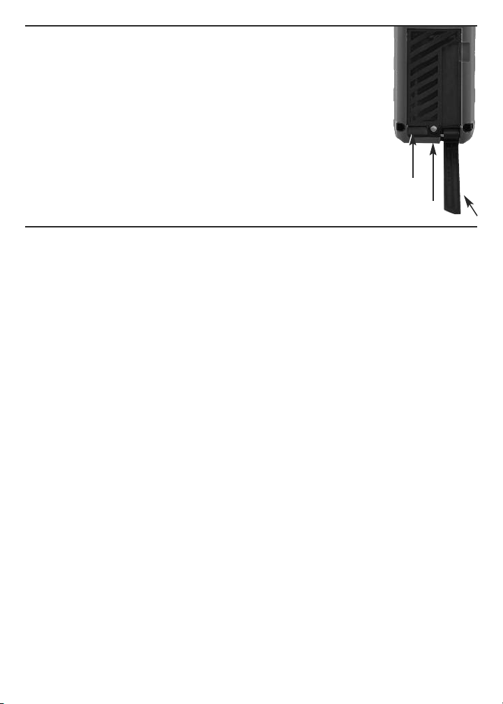
INSTALL BATTERIES
The LDM is ready to use after you install the two supplied “AAA”
batteries in a compartment in the back of the unit. To open the
compartment, use the included flat-head screwdriver to loosen
the single screw holding the battery compartment cover in place
(see photo at right). After opening the extension ruler, remove
the cover and set it aside. Position the batteries so their polarity
marks match the diagram inside the compartment. Replace the
cover and tighten the screw to secure it.
LIFT
COVER
HERE
SCREW
EXTENSION RULER
OPERATING INSTRUCTIONS
POWERING ON AND OFF
To turn the LDM on
backlight and laser. It also sounds a chirp, causes the laser icon (Callout 2 of Fig. 2)
to flash, and places the LDM in direct distance measurement mode.
While the LDM is powered on, any push of any button produces a chirp to confirm
that some action has taken place (a measurement was made, an operating mode or
measurement unit was changed, etc.). The only actions that are
by a chirp are the laser timing out (after 30 seconds of inactivity) for safety reasons
and the backlight timing out (after 10 seconds of inactivity) to conserve battery
charge. The LDM also chirps when it automatically powers off after 3 minutes of
inactivity. The chirp cannot be disabled.
To turn the LDM off
will respond with a chirp as it powers off.
, press and hold the button. This activates the display,
not
accompanied
manually, press and hold the button. The instrument
QUICK START INSTRUCTIONS
To make a quick distance measurement:
1. Power the LDM on.
2. Within 30 seconds, point the top of the instrument at a target and press the
button. The distance to the target—in the default measurement unit of
feet with decimal fraction—will be displayed on the bottom line of the display. The
top line will indicate the LDM’s angle with respect to the horizontal. When making
direct distance measurements, always orient the LDM so the top line reads close
to
0.0º
.
8
Page 9

To temporarily change the distance measurement unit, follow the instructions
MEASURE
ON
on p. 10.
If the laser has timed out (i.e., it has been on for more than 30 seconds), or if you
have just made a measurement, you will not see a red dot on the target and there
will be no flashing icon (Callout 2 of Fig. 2) on the display.
To make a distance
measurement with the laser off, you must press the button
—once to activate the laser and once to make the measurement.
twice
See page 20 for additional operating tips.
CHOOSING A MEASUREMENT REFERENCE
The LDM can reference its measurements from the top or bottom of the housing, or
the bottom of the extension ruler (see photo on page 8 for its location).
For most distance measurements, choosing the bottom of the housing as the
reference produces the most accurate readings. Doing so allows you to hold the
bottom of the LDM horizontally against one wall of a room, or vertically against the
floor, and send the laser beam out the top of the unit toward the opposite wall or
the ceiling.
However, for continuous distance (tracking) measurements (see p. 11), using the
top of the LDM as the reference produces the most accurate readings. In tracking
mode, you typically walk the instrument back from a wall to a distance specified on
a blueprint. In this case, what you want to measure is the distance to the wall from
the top of the unit.
The button on the front panel lets you select the bottom or top of the
housing, or the bottom of the extension ruler, as the measurement reference. The
three black icons shown in Fig. 3 below are the corresponding display indications.
When the LDM is powered off and on again, the measurement reference
automatically resets to the default: the bottom of the unit.
Fig. 3. Referencing
measurements
from the bottom (left)
and top (center)
of the LDM housing,
or the bottom of the
LDM’s extension ruler (right)
9
Page 10

CLEARING VALUES/UNDOING ACTIONS
CLEAR
OFF
MEASURE
ON
MEASURE
ON
When pressed briefly, the two-function button:
1. Works like the “Clear Entry” button on a calculator to clear the last value
entered in a calculation sequence
2. Works like the “Undo” command on a computer menu to cancel the last
action selected
CHANGING THE MEASUREMENT UNIT
The LDM’s default distance measurement unit is feet with decimal fraction. The
2
default area measurement unit is square feet, expressed as ft
3
measurement unit is cubic feet, expressed as ft
.
To temporarily change the distance measurement unit
. The default volume
, press and hold the
button as many times as necessary until the desired unit appears on the
bottom display line. The alternatives to feet with decimal fraction, in order, are
inches (in), feet + fractional inches (expressed as X'Y", where X is a whole number
and Y is a whole number plus a common fraction), and meters (m).
When the LDM is powered off and on again, the distance measurement unit
automatically resets to the default: feet with decimal fraction.
TURNING THE BACKLIGHT ON AND OFF
To turn the display backlight on
, briefly press the button. The backlight
will remain on for ten seconds and then automatically turn off (silently) to conserve
battery charge.
MEASURING DISTANCES
Direct Measurements
To measure the distance to a target:
1. Power on the LDM and select a measurement unit, an appropriate measurement
reference (in most cases, the bottom of the LDM) and an appropriate backlight
state (on for indoor work, off for outdoor work).
2. If the laser icon (Callout 2 of Fig. 2) is not flashing and the laser pointer is
not
visible, press the button to activate the laser. Doing so will sound a
chirp, cause the laser icon to flash, and place the LDM in direct distance
measurement mode.
3. After confirming that the laser is on, level the LDM horizontally by referring to the
top line of the display, aim the unit at a target, and press the button. The
10
Page 11

LDM will chirp, and the distance to the target—in the default distance unit of feet
15
/
16
5’01”
0.0º
➤
0.0º
13
/
16
3
/
4
1
/
8
113 04
53 03
3 03
➤
with decimal fraction—will appear on the bottom line of the display.
To temporarily change the distance measurement unit, follow the instructions on
p. 10. Figure 4 is a screen shot of a measurement of
5 feet, 1 and 15/16 inches.
Fig. 4. A direct distance measurement of
5 feet, 1 and 15/16 inches
In direct distance measurement mode, you can display up to
three consecutive measurements in the order in which they
were made. Fig. 5 is a screen shot which shows the values
of three direct distance measurements made in top-tobottom order.
Fig. 5. Three direct distance measurements made in
order from top to bottom
Continuous Distance Measurement
(Distance Tracking)
This operating mode is ideal for transferring measurements
from construction plans or blueprints. In practice, you walk the LDM back from a
wall a specified distance while the unit tracks its own position by measuring the
distance to the wall twice per second. As you make these dynamic measurements
and you close in on the specified distance, the LDM takes note of the closest and
farthest you have been from the wall and displays these minimum and maximum
distances along with the final distance.
Before entering continuous distance measurement mode, be sure to temporarily
change the measurement reference from the bottom of the housing to the top by
briefly pressing the button (see p. 9). Next, hold the LDM horizontally with its
top against the wall. Then, after making sure that the laser is on, press the
button and back away from the wall while continuing to point the laser at the wall.
Initially (until the LDM reaches its minimum measurement distance of several
inches from the wall), the display will show an
minimum measurement threshold is passed, the LDM will begin to measure the
distance from to the wall twice per second. The measurements, accompanied by
chirps twice per second, will be shown and continuously updated on the bottom
line of the display. At the same time, the second and third display lines continuously
update the LDM’s minimum and maximum distance from the wall during this
measurement session.
Error 261
message. Once the
11
Page 12

When you and the LDM reach the specified distance, press the button to
MEASURE
ON
MEASURE
ON
u
➤
0.0º
11.33
10.000
0.112
0.0º
16.325
18.415
2.090
➤
silence the chirping. The subsequent inactivity triggers the 30-second countdown
to laser power off and the 3-minute countdown to LDM power off. The LDM’s MIN,
MAX and current distance values remain on the display (Fig. 6) until it powers off
automatically.
Fig. 6. The results of using continuous measurement
to step off a specified distance (10m) from a
wall
Adding and Subtracting Distances
The LDM has a front-panel button that makes it easy to add
or subtract a distance measurement from an existing measurement, in effect
turning the earlier measurement into a baseline. This addition/subtraction function
comes in handy when accumulating multiple distance measurements.
For example, consider how the LDM could speed up the measurements needed to
lay out a long brick wall of multiple sections that are not in a straight line. Once
stakes, strings and frame are in place, the LDM could accurately measure the
length of each section by shooting from one stake to the next. It would also keep a
running total of these measurements and display the final result—the wall’s
perimeter—on its bottom line.
To add a measurement
briefly press th
bottom line to the second line and a flashing icon will appear at the left of five
dashes (representing the distance value to be added) on the third line. Then press
the button while aiming the laser
measurement was made
the dashes on the third line with that value, and display the sum of the two
measurements on the bottom line (Fig. 7).
Fig. 7. A display showing the addition of a 16.325 ft.
e
measurement to a measurement of 2.090 feet
to an existing measurement displayed on the bottom line,
button. The earlier measurement will be moved from the
at the point from which the first
. The LDM will measure the distance to that point, replace
To subtract a measurement
displayed on the bottom line, press and hold the button.
The earlier measurement will be moved from the bottom line
12
from an existing measurement
Page 13

to the second line and a flashing icon will appear at the left of five dashes
MEASURE
ON
(representing the distance value to be subtracted) on the third line. Then press the
button while aiming the laser at the point from which the first
measurement was made. The LDM will measure the distance to that point, replace
the dashes on the third line with that value, and display the difference of the two
measurements on the bottom line.
Indirect Measurements of Height or Length using Triangulation
The LDM can use triangulation (one type of indirect measurement based on
Pythagorean geometry) to calculate the height or length of an object from a
distance. The instrument can perform three kinds of Pythagorean calculations:
Triangulation with two inputs.
•
This kind of distance measurement can be
made only for distances that present you with a right angle. A good example is
measuring the height of a building from across the street at ground level (Fig. 8).
Because the LDM and the bottom of the building are both at ground level, the side
of the building (whose height “A” is unknown) forms one leg of a right triangle
whose other leg is the distance across the street (“B” in the figure). In other
words, you can use triangulation to determine the height “A” using only two
inputs because “A” is perpendicular to “B”—one of the distances you can
measure. The LDM can measure “B” as well as the distance to the top of the
building (“C” in the figure), which is the hypotenuse of the right triangle. Once
the LDM has determined the values of “B” and “C”, it calculates the value of “A”
according to Pythagoras’ famous equation: A
2
+ B2= C2.
C
A
Fig. 8. Triangulating a height using two inputs
B
•
Triangulation with three inputs.
made for distances that do
not
This kind of distance measurement can be
present you with a right angle. A good example is
measuring the height of a building from another building across the street through
an open fourth-floor window (Fig. 9). Because the LDM and the bottom of the
target building are not both at ground level, you must measure one common leg
“B1/B2” (which is perpendicular to the wall of the building) and the hypotenuses of
13
Page 14

two right triangles “C1” and “C2”. Once these two values are known, the LDM can
MEASURE
ON
MEASURE
ON
solve two Pythagorean equations for the missing values of the other two legs
(“A1” and “A2”). The final calculation, which solves for A—the height of the
building—is A = A1 + A2.
C1
Fig. 9. Triangulating a height using three inputs
A1
B1/B2
• Auto height measurement. Using a slightly
different technique (see Fig. 10), the LDM can
quickly calculate the height of any object using
C2
A=A1+A2
A2
only two inputs.
Fig. 10. Automatic calculation of a height using
two inputs
To measure the height of an object using triangulation
with two inputs:
1. First make sure that the line of sight from the LDM to the bottom of the object
forms a right angle.
2. Use the button to choose the top of the LDM as the measurement
reference. Also make sure the laser is on.
3. Press the button three times. A icon will appear on the left side of the
display with the hypotenuse flashing.
4. Aim the laser at the top of the object and press the button. The distance
measured (the hypotenuse) will appear on the second line of the display and the
horizontal leg of the on-screen triangle will begin flashing.
5.
Without moving the LDM
, and keeping it as horizontal as possible, aim the laser
at the bottom of the object and press the button. The distance measured
will appear on the third line of the display and the height of the object will appear
on the bottom (summary) line. The final display will look similar to Fig. 11 at the
top of the next page.
14
Page 15

Fig. 11. A two-input indirect measurement of the
MEASURE
ON
MEASURE
ON
MEASURE
ON
MEASURE
ON
MEASURE
ON
0.0º
5.846
4.990
7.687
height of a tree standing 4.990 meters tall
To automatically measure the height of any object
using triangulation with two inputs:
Use the button to choose the top of the LDM as the
1.
measurement reference. Also make sure the laser is on.
2.
Press the button five times. An isosceles triangle will appear on the left side
of the display with its upper leg flashing.
3.
Aim the laser at the top of the object and press the button. The distance
measured will appear on the second line of the display and the triangle's lower
leg will begin flashing.
4. Without moving the LDM
, press the button again. The distance
measured will appear on the third line of the display and the height of the object
will appear on the bottom (summary) line.
To measure the height of an object using triangulation with three inputs:
1.
Use the button to choose the top of the LDM as the measurement
reference. Also make sure the laser is on.
2.
Press the button twice. A icon will appear on the left side of the display
with the upper hypotenuse flashing.
3.
Aim the laser at the top of the object and press the button. The distance
measured will appear on the top line of the display and the horizontal line
bisecting the on-screen triangle will begin flashing.
4. Without moving the LDM
and keeping it as horizontal as possible, aim the laser
directly at the object and press the button. The distance measured will
appear on the second line of the display, the horizontal line will stop flashing, and
the lower hypotenuse will begin flashing.
5. Without moving the LDM
, aim the laser at the bottom of the object and press
the button. The distance measured will appear on the third line of the
display and the height of the object will appear on the bottom (summary) line.
The final display will look similar to Fig. 12 at the top of the next page.
15
Page 16

Fig. 12. A three-input indirect measurement of the
MEASURE
ON
MEASURE
ON
➤
19.54
19.02
14.27
17.90
2
5
/
8
51 10
13
/
16
1
/
2
9 06
155.65
16 03
height of a wall standing 14.27 ft. tall
MEASURING AREAS & PERIMETERS
The LDM can calculate the area of a square or rectangular room or space by
measuring its length and width and multiplying the two values. It can also calculate
the perimeter of the room or space by adding the length and width and mulitplying
by two.
To measure an area or perimeter:
1. Make sure the LDM is using its bottom as the measurement reference and that
the laser is on.
2. Press the button once. A icon will appear on the left side of the display
with its bottom leg flashing.
3. Holding the bottom of the LDM against one wall of the room or space, aim the
laser pointer at the opposite wall and press and hold the button. The
distance measured will appear on the top line of the display, the bottom leg of
the parallelogram will stop flashing, and the right leg of the parallelogram will
begin flashing.
4. Move the LDM to an adjacent wall of the room or space and hold its bottom
against that wall. Aim the laser at the opposite wall and press the
button. The distance measured will appear on the second line of the display and
the area of the room or space—in “square” units—will appear on the bottom
line. The calculated perimeter of the room or space will appear on the third line
of the display. The final display will look similar to Fig. 13.
Fig. 13. Calculation of the perimeter
and area of a room measuring
16 feet, 3 and 13/16 inches
by 9 feet, 6 and 1/2 inches
16
Page 17

MEASURING VOLUMES
MEASURE
ON
MEASURE
ON
MEASURE
ON
3.959
5.106
58.582
2.898
3
The LDM can calculate the volume of a square or rectangular room or space by
measuring its height, depth and width and multiplying the three values.
To measure a volume:
1. Make sure the LDM is using its bottom as the measurement reference and that
the laser is on.
2. Press the button twice. A icon will appear on the left side of the display
with its top front “width” leg flashing.
3. Holding the bottom of the LDM against the floor of the room or space, aim the
laser pointer at the ceiling and press the button. The distance measured
will appear on the top line of the display, the top front “width” leg of the cube will
stop flashing, and the top right “depth” leg of the cube will begin flashing.
4. Move the LDM to one wall of the room or space and hold its rear against that
wall. Aim the laser pointer at the opposite wall and press the button. The
distance measured will appear on the second line of the display, the top right
“depth” leg of the cube will stop flashing, and the right front “height” leg of the
cube will begin flashing. The third line of the display will display the calculated
area of the plane bounded by the width and depth of the volume.
5. Move the LDM to an adjacent wall of the room or space and hold its bottom
against that wall. Aim the laser at the opposite wall and press the
button. The distance measured will replace the planar area on the third line of the
display and the volume of the room or space—in “cubic” units—will appear on
the bottom line. The final display will look similar to Fig.14.
Fig. 14. Calculation of the volume of a room
measuring 3.959 x 2.898 x 5.106 meters
RECALLING STORED MEASUREMENTS/
CALCULATIONS
The LDM automatically stores its last 20 measurements or calculations and retains
them in memory after being powered off. The records also are unaffected by a
battery discharge or battery change. Once the memory is full, the next
17
Page 18

measurement or calculation overwrites the oldest record in a first in-first out (FIFO)
▲
▼
▲▼▲
▼
0.0º
6.02
4
scheme. Record #1 is the most recent measurement or calculation, and Record #20
is the oldest. The records are recalled sequentially, using the front-panel
button. Records cannot be deleted individually or in bulk.
To recall a record
, press the button. The value of the first (most recent)
measurement or calculation will appear on the bottom line, and a “1” will appear
over the icon near the top of the display, below the battery charge indicator.
Briefly press, or press and hold, the button to navigate up or down through the
memory to the desired record number (Fig. 15). Repeatedly
pressing the button briefly recalls stored records in reverse
chronological order. Repeatedly pressing and holding the
button recalls the records in chronological order. Tip: Pressing
and holding the button with Record #1 displayed recalls
Record #20.
Fig. 15. The LDM’s fourth most recent measurement
or calculation had a value of 6.02 inches
™
USING THE LDM WITH THE ToolSmart
APP
AND AN APPLE iOS OR ANDROID PHONE
To download measurements and calculations made by the LDM to an Apple iOS or
Android smartphone, begin by downloading the ToolSmart
™
app from the iTunes
Store or Google Play Store to your mobile device.
Once you have downloaded the app, install it. Then, pair the LDM and your phone
by activating Bluetooth on your phone and pressing the button on the LDM.
A tutorial on the app explains how to save LDM measurements and calculations to
your phone and overlay them on photos of your project made with the phone’s
camera.
18
Page 19

SPECIFICATIONS
Measurement Range (indoor) 8 in. to 100 ft. (200mm to 30m)
Measurement Accuracy ±1/16 in. (±1.5mm)
Resolution 1mm
Display Unit Options feet with decimal fraction (default), feet plus fractional
inches, inches, meters
Response Time 2 seconds, max
Laser Type, Wavelength, Power Class 2, 630 to 660nm, < 1mW
Operating Modes Direct Distance Measurement, Distance Addition/
Subtraction, Continuous Distance Measurement
(Distance Tracking), Indirect Distance Measurement
(Triangulation) with 2 or 3 inputs, Auto Height
Measurement, Area and Perimeter Measurement,
Volume Measurement
Display 4-line backlit LCD measuring 1-3/4 in. (45mm) diagonal
Memory 20 measurements
Splashproof and Dustproof To IP54 standard
Auto Power Off After 3 minutes of inactivity
Auto Laser Off After 30 seconds of inactivity
Auto Backlight Off After 10 seconds of inactivity
Battery Life 3000 measurements, typical
Operating Temperature 32° to 104°F (0° to 40°C)
Storage Temperature 14º to 140ºF (-10º to 60ºC) @ <85% R.H.
Power Source 2 “AAA” batteries
Dimensions 4.5 x 2.0 x 1.3 in. (115 x 52 x 32mm)
Weight 4.2 oz. (120g), excluding batteries
19
Page 20

OPERATING & MAINTENANCE TIPS
MEASURE
ON
MEASURE
ON
Because the laser silently auto powers off after 30 seconds of inactivity while the
LDM remains powered on, you’ll often find that when you press the button
expecting to make a measurement, all you have done is reactivate the laser. In this
case, you have to press the button a second time to take a reading.
When measuring horizontal distances, keep the LDM as horizontal as possible,
using the digital angle reading on the top line of the display as a guide.
When measuring long distances, use a target plate made of white paper or
cardboard. Using a monopod or resting the LDM on a surface (rather than holding it
in your hand) helps to steady the laser on distant targets.
The LDM will almost always register an “Error 204” if the target is an LCD or
plasma computer or TV screen. The calculation error results because the display
absorbs the incoming beam and reflects nothing back to the LDM.
The following errors can be corrected:
Code Cause Corrective Measure
Error 204 Calculation error Repeat the measurement(s)
Error 252 Temperature too high Cool down the LDM
Error 220 Low battery Install fresh batteries
Error 253 Temperature too low Warm up the LDM
Error 255 Received signal too weak/ Use white target plate
Measurement time too long
Error 256 Received signal too strong Use target plate
(target too reflective)
Error 500 Hardware/uncertainty error Power the LDM off and on
Replace the batteries (see page 8) when the on-screen battery icon
indicates that their charge has been depleted.
Use Alkaline batteries only.
To avoid having old batteries leak and ruin the LDM, remove the batteries when you
do not expect to use the instrument for a long period of time (several months).
Clean the LDM with wiping it with a damp soft cloth. Never use solvents or
abrasives.
Keep the LDM away from water, toxic environments and temperature extremes.
20
Page 21

WARRANTY INFORMATION
General warrants its instruments and accessories, and digital tools products against
defects in material or workmanship for one year from the date of purchase unless
otherwise stated on the packaging, manual, and/or marketing materials. General
also warrants its non-digital tools products against defects in material or
workmanship on a limited lifetime term.
General will replace or repair the defective unit, at its option, subject to verification
of the defect.
This warranty does not apply to defects resulting from abuse, neglect, accident,
unauthorized repair, alteration, or unreasonable use of the product. It also does not
cover products purchased from unauthorized distributors. A proof of purchase must
accompany each warranty claim.
Any implied warranties arising from the sale of a General product, including but not
limited to implied warranties of merchantability and fitness for a particular purpose,
are limited to the above. General shall not be liable for loss of use of the product or
other incidental or consequential damages, expenses, or economic loss, or for any
claim of such damage, expenses, or economic loss.
State laws vary. The above limitations or exclusions may not apply to you.
For more details or to file a warranty claim, contact General Tools & Instruments
Technical Support at techsupport@generatools.com.
21
Page 22

RETURN FOR REPAIR POLICY
Every effort has been made to provide you with a reliable product of superior
quality. However, in the event your instrument requires repair, please contact our
Customer Service to obtain an RGA (Return Goods Authorization) number before
forwarding the unit via prepaid freight to the attention of our Service Center at this
address:
22
Page 23

FCC STATEMENT
This device complies with part 15 of the FCC Rules. Operation is subject to the
following two conditions: (1) This device may not cause harmful interference,
and (2) This device must accept any interference received, including
interference that may cause undesired operation.
This equipment has been tested and found to comply with the limits for a Class
B digital device, pursuant to part 15 of the FCC Rules. These limits are designed
to provide reasonable protection against harmful interference in a residential
installation. This equipment generates, uses and can radiate radio frequency
energy and, if not installed and used in accordance with the instructions, may
cause harmful interference to radio communications.
However, there is no guarantee that interference will not occur in a particular
installation. If this equipment does cause harmful interference to radio or
television reception, which can be determined by turning the equipment off and
on, the user is encouraged to try to correct the interference by one or more of
the following measures:
• Reorient or relocate the receiving antenna.
• Increase the separation between the equipment and receiver.
• Connect the equipment to a different circuit than the one the receiver is
connected to.
• Consult your supplier or an experienced radio/TV technician for help.
Caution: Any changes or modifications not expressly approved by the party
responsible for compliance could void the user's authority to operate the
equipment.
23
Page 24

General Tools & Instruments
GeneralToolsNYC
NOTICE - WE ARE NOT RESPONSIBLE FOR TYPOGRAPHICAL ERRORS.
24
99 Washington Street
Melrose, MA 02176
Phone 781-665-1400
Toll Free 1-800-517-8431
Visit us at www.TestEquipmentDepot.com
Specifications subject to change without notice
©2016 GENERAL TOOLS & INSTRUMENTS
MAN# TS01
01/14/16
 Loading...